EP3361925B1 - Schwammbrettvorrichtung - Google Patents
Schwammbrettvorrichtung Download PDFInfo
- Publication number
- EP3361925B1 EP3361925B1 EP15784597.5A EP15784597A EP3361925B1 EP 3361925 B1 EP3361925 B1 EP 3361925B1 EP 15784597 A EP15784597 A EP 15784597A EP 3361925 B1 EP3361925 B1 EP 3361925B1
- Authority
- EP
- European Patent Office
- Prior art keywords
- base plate
- pressure
- perforated base
- plate
- pressure element
- Prior art date
- Legal status (The legal status is an assumption and is not a legal conclusion. Google has not performed a legal analysis and makes no representation as to the accuracy of the status listed.)
- Active
Links
Images



Classifications
-
- A—HUMAN NECESSITIES
- A47—FURNITURE; DOMESTIC ARTICLES OR APPLIANCES; COFFEE MILLS; SPICE MILLS; SUCTION CLEANERS IN GENERAL
- A47L—DOMESTIC WASHING OR CLEANING; SUCTION CLEANERS IN GENERAL
- A47L13/00—Implements for cleaning floors, carpets, furniture, walls, or wall coverings
- A47L13/10—Scrubbing; Scouring; Cleaning; Polishing
- A47L13/50—Auxiliary implements
- A47L13/58—Wringers for scouring pads, mops, or the like, combined with buckets
- A47L13/59—Wringers for scouring pads, mops, or the like, combined with buckets with movable squeezing members
Definitions
- the present invention relates to the field of sponge boards, and more particularly to a device for squeezing water out of a sponge board.
- Sponge boards are commonly used in a number of tiling and plastering operations, such as washing of tiles to remove grout residues and providing an even finish to joints and plaster. In these operations excess water including sand, grout residues etc. must frequently be removed from the sponge board (or sponge float) to avoid washing away too much of the joint or plaster, and avoid diluting the grout in the joints.
- the device comprises a hinged pressure element arranged to squeeze a sponge board towards a perforated plate, such that the water is drained into a bucket.
- the pressure element is parallel to the perforated plate at a fixed distance from the perforated plate.
- the device is thus able to evenly squeeze a sponge board having a set thickness. Sponge boards of larger or smaller thickness will not be squeezed evenly since the pressure element will not be parallel to the perforated plate at the required distance, and the water remaining in the sponge board will be distributed unevenly.
- the present invention provides a device for squeezing water out of a sponge board.
- the device is defined in the appended claims and in the following:
- the invention provides a device for squeezing water out of a sponge board having a bow handle arranged on a backing plate, the device comprising a perforated base plate and a pressure element, wherein
- the multiple drainage openings are sized to drain sand and grout residue in addition to the water.
- the means for changing the predetermined distance of the at least one pressure surface in the second position comprises at least one interchangeable adapter on the pressure element, said interchangeable adapter comprising the at least one pressure surface.
- the interchangeable adapter comprises a first plate element comprising the at least one pressure surface, wherein the thickness of the first plate element decides the size of the predetermined distance.
- the at least one interchangeable adapter comprises a first and a second interconnected plate element, each plate element comprising a pressure surface, the first and the second plate element being parallel and of different thickness, such that the interchangeable adapter may be arranged with the pressure surface of the first or the second plate element facing the upper surface of the perforated base plate to provide a first or a second predetermined distance, respectively, between the at least one pressure surface and the upper surface of the perforated base plate when the pressure element is in the second position.
- the first and the second plate element are interconnected by a connecting element, such that the interchangeable adapter may be releasably fastened to the pressure element, preferably by being clipped onto the pressure element.
- the interchangeable adapter provides increased stiffness to the pressure element.
- the pressure element is pretensioned towards the first position.
- the pressure element may be pretensioned by a spring, and preferably by an internal spring in the at least one hinge.
- the perforated base plate comprises guide rails for centering the sponge board upon the perforated base plate.
- the pressure element may be locked in the second position, preferably by at least one locking arm pivotably connected to the perforated base plate or a guide rail.
- the pressure element comprises two parallel arms interconnected by the push handle, and the recess is provided by a longitudinal opening formed between the two parallel arms.
- the at least one interchangeable adapter is arranged on the parallel arms.
- the push handle is bow shaped and comprises an upper rounded surface extending away from the perforated base plate.
- the device comprises stopping means for preventing the pressure element from pivoting beyond the second position.
- the stopping means may for instance comprise at least one stopping block arranged on the perforated base plate, and at least one cooperating stopping block or stopping surface arranged on the pressure element.
- the means for changing the predetermined distance of the at least one pressure surface in the second position comprises means for raising or lowering the level of the at least one hinge in relation to the perforated base plate.
- Such means may comprise any type of connection between the at least one hinge and the perforated base plate which may be extended or shortened in order to change the predetermined distance.
- pivoting beyond the second position is intended to mean that the at least one pressure surface may not be closer to the perforated plate than it is in the second position.
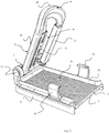
- a preferred embodiment of the device according to the invention is shown in fig. 1 .
- the device is suitable for evenly squeezing water out of a sponge board.
- a sponge board 1 comprises a sponge 26, a backing plate 14 on which the sponge is fastened, and a handle 2.
- the handle is usually bow shaped and attached to the backing plate.
- the handle may in stead of being bow shaped comprise a shaft which is pivotably connected to the backing plate (not shown).
- the device comprises a perforated base plate 3 pivotably connected by hinges 12 to a pressure element 4 having two pressure surfaces 11.
- the perforated base plate comprises multiple drainage openings 5 to allow water, sand and grout residues from a sponge board 1 to drain from the upper surface 6 of the base plate.
- the device is arranged on a suitable wash bucket (see fig. 8 ) into which the water is collected.
- the perforated base plate has flanges 21 for arranging the device on or in the suitable bucket. The flanges also ensure that the perforated base plate 3 is sufficiently rigid, i.e. does not bend during use.
- the pressure element 4 comprises two parallel arms 20 interconnected by a push handle 10.
- the two parallel arms are arranged at a distance from each other, such that an opening or recess 9 is formed between them.
- the parallel arms are connected to the perforated base plate by the hinges 12.
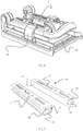
- Each of the parallel arms 20 comprises an interchangeable adapter 13 featuring a pressure surface 11 (i.e. means for changing the predetermined distance), see also fig. 5 .
- the interchangeable adapters 13 are designed as longitudinal elements which may be clipped onto the parallel arms.
- the longitudinal element comprises a first 15 and a second 16 plate element interconnected by a third plate element 17 (i.e. a connecting element).
- the adapters When clipped onto the parallel arms 20, one side of the first 15 or the second 16 plate elements constitutes the pressure surface 11 of the pressure element 4.
- the thickness of the first plate element 15 is smaller than the thickness of the second plate element 16.
- the adapters By being clipped onto the parallel arms, the adapters also improve the bending stiffness of the pressure element.
- the predetermined distance may also be varied without the use of interchangeable adapters, for instance by having means for raising and/or lowering the level of the hinges 12 in relation to the perforated base plate (i.e. means for changing the predetermined distance), see fig. 9 and description below.
- the pressure element may pivot between a first and a second position.
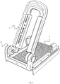
- the pressure element 4 extends away from the perforated base plate 3, allowing a sponge board 1 to be arranged on the upper surface of said plate, see fig. 1 to 3 .
- the pressure element is arranged such that the pressure surfaces 11 are parallel to the upper surface 6 of the perforated plate.
- the pressure surfaces are at a predetermined distance from the perforated base plate. The size of the desired predetermined distance will depend on the type of sponge board 1 to be used.
- the sponge 26 have a thickness of 30 mm or 35 mm, while the thickness of the backing board remains the same. If the predetermined distance in the second position is not adapted to the correct sponge board thickness, an uneven pressure is applied to the sponge causing too much water to remain in parts of the sponge.
- the appropriate first 15 or second 16 plate element for providing the pressure surface 11 for a specific sponge board a correct predetermined distance and an even pressure on the sponge is achieved.
- a sponge board for washing of tiles will commonly feature a sponge 26 with a thickness of 30 mm and require a predetermined distance of about 9 mm plus the thickness of the backing plate, while a similar sponge board having a sponge with a thickness of 35 mm will require a larger predetermined distance of about 12 mm plus the thickness of the backing plate.
- sponge boards for other types of operation such as plaster finishing, may require sponges changing in thickness from about 10 mm to 40 mm and the required predetermined distance will vary accordingly. Further, the required predetermined distance will also depend on the type of sponge material, i.e. the compressibility of the sponge, and the thickness of the backing plate.
- the guide rails 18 arranged on the perforated base plate ensures that the sponge board 1 is centered on the perforated base plate.
- the connection between the handle 2 and the backing plate 14 comprises a raised section on the backing plate to ensure sufficient strength of the connection. If the sponge board is arranged too far off center on the perforated base plate, parts of the pressure surface 11 may push against the raised section in the second position, thus causing an uneven pressure on the sponge.
- At least one of the hinges 12 comprises an internal spring pretensioned towards moving the pressure element into the first position.
- the spring is arranged inside the hinge to protect it from wear due to the presence of sand and grout residues in the water squeezed out of the sponge board.
- the device is intended to be arranged on a wash bucket, see fig. 8 .
- Such a wash bucket 22 comprises a handle 23 for carrying the bucket. When the device is in the first position, the handle 23 of the bucket would have to extend far above said bucket to pass above the pressure element 4 extending away from the perforated base plate 3.
- the pressure element 4 may be locked in the second position by use of the locking arms 19, see fig. 4 and fig. 8 .
- the locking arms are pivotably connected to the guide rails or the perforated base plate.
- a further advantage of being able to lock the pressure element in the second position is that the bow handle of a sponge board may function as a carrying handle for the device itself.
- the push handle 10 at the second end 8 of the pressure element is bow shaped and comprises an upper rounded surface extending away from the perforated base plate.
- the device may also be used for sponge boards comprising a pole handle, as long as the pole handle is pivotably connected to the backing plate of the sponge board.
- the device may further comprise stopping means 24, 25 for preventing the pressure element 4 to pivot beyond the second position, see figs. 6 and 7 .
- the stopping means comprises stopping blocks 24 arranged on the perforated base plate 3, in this case the stopping blocks 24 are integrated in the guide rails 18, and a cooperative stopping block 25 arranged on each of the parallel arms 20.
- Fig. 9 displays an expanded cutout to better show the means for raising or lowering the level of the hinges 12.
- the hinges are connected to a flange 27 on the perforated base plate 3 by use of screws/bolts 28.
- the screws/bolts are fastened via vertically extending longitudinal openings 29 in the flange, such that the level of the hinges, and consequently the predetermined distance at which the pressure surfaces 11 of the pressure element 4 and the perforated base plate 3 are parallel, may be varied in a vertical direction (vertical in relation to the horizontally arranged base plate 3).
- the level of the hinges 12 may be varied, would be apparent to the skilled person based on the present disclosure.
- Such embodiments may feature any type of vertically extendable connection between the hinges and the perforated base plate, such as telescopic arms that may be locked at a required level (e.g.
- each of the vertically extending longitudinal openings 29, shown in fig. 9 is replaced by multiple openings arranged at levels corresponding to different predetermined distances, and similar.
- All of the described embodiments provide a device wherein the action of squeezing water out of a sponge board only requires a single movement, and which action provides an even pressure over the length of the sponge board ensuring that a correct amount of water is squeezed out of the sponge, each and every time the action is repeated, without any excess water being present in parts of the sponge.
Landscapes
- Cleaning Implements For Floors, Carpets, Furniture, Walls, And The Like (AREA)
- Food-Manufacturing Devices (AREA)
Claims (14)
- Vorrichtung zum Auspressen von Wasser aus einem Schwammbrett (1), das einen Bügelgriff (2) aufweist, der auf einer Trägerplatte (14) angeordnet ist, wobei die Vorrichtung eine perforierte Grundplatte (3) und ein Druckelement (4) umfasst, wobei- die perforierte Grundplatte (3) mehrere Ablauföffnungen (5) umfasst, um zu ermöglichen, dass Wasser von einer oberen Fläche (6) der perforierten Grundplatte abläuft; und- das Druckelement (4) ein erstes Ende (7), ein zweites Ende (8), mindestens eine Druckfläche (11) und eine Aussparung (9) umfasst, wobei die Aussparung derart angeordnet ist, dass sie den Bügelgriff (2) aufnimmt, wenn das Schwammbrett (1) auf der oberen Fläche (6) der perforierten Grundplatte (3) angeordnet ist, das erste Ende (7) durch mindestens ein Gelenk (12) schwenkbar mit der perforierten Grundplatte verbunden ist und das zweite Ende (8) distal von dem ersten Ende gelegen ist und einen Druckgriff (10) umfasst, und das Druckelement (4) zwischen einer ersten Position, in der das Schwammbrett (1) auf der oberen Fläche (6) der perforierten Grundplatte (3) angeordnet sein kann, und einer zweiten Position, bei der die mindestens eine Druckfläche (11) sich parallel zu und in einem vorgegebenen Abstand von der oberen Fläche (6) der perforierten Platte (3) befindet, geschwenkt werden kann, dadurch gekennzeichnet, dass die Vorrichtung ein Mittel (13) zum Ändern des vorgegebenen Abstands der mindestens einen Druckfläche (11) in der zweiten Position umfasst.
- Vorrichtung nach Anspruch 1, wobei das Mittel zum Ändern des vorgegebenen Abstands der mindestens einen Druckfläche (11) in der zweiten Position mindestens einen austauschbaren Adapter (13) an dem Druckelement (4) umfasst, wobei der austauschbare Adapter die mindestens eine Druckfläche (11) umfasst.
- Vorrichtung nach Anspruch 2, wobei der austauschbare Adapter (13) ein erstes Plattenelement (15) umfasst, das die mindestens eine Druckfläche (11) umfasst, wobei die Dicke des ersten Plattenelements über die Größe des vorgegebenen Abstands entscheidet.
- Vorrichtung nach Anspruch 2 oder 3, wobei der wenigstens eine austauschbare Adapter (13) ein erstes (15) und ein zweites (16) miteinander verbundenes Plattenelement umfasst, wobei jedes Plattenelement (15, 16) eine Druckfläche (11) umfasst, das erste und das zweite Plattenelement parallel sind und eine unterschiedliche Dicke aufweisen, derart dass der austauschbare Adapter (13) mit der Druckfläche (11) des ersten oder des zweiten Plattenelements der oberen Fläche (6) der perforierten Grundplatte (3) zugewandt angeordnet werden kann, um einen ersten beziehungsweise einen zweiten vorgegebenen Abstand zwischen der mindestens einen Druckfläche (11) und der oberen Fläche (6) der perforierten Grundplatte bereitzustellen, wenn sich das Druckelement (4) in der zweiten Position befindet.
- Vorrichtung nach Anspruch 4, wobei das erste (15) und das zweite (16) Plattenelement durch ein Verbindungselement (17) derart miteinander verbunden sind, dass der austauschbare Adapter (13) lösbar an dem Druckelement befestigt sein kann, vorzugsweise indem es auf das Druckelement geklemmt wird.
- Vorrichtung nach einem der Ansprüche 2 bis 5, wobei der austauschbare Adapter (13) dem Druckelement (4) eine erhöhte Steifigkeit bereitstellt.
- Vorrichtung nach einem der vorhergehenden Ansprüche, wobei das Druckelement (4) in Richtung der ersten Position vorgespannt ist, vorzugsweise durch eine innere Feder in dem mindestens einen Gelenk.
- Vorrichtung nach einem der vorhergehenden Ansprüche, wobei die perforierte Grundplatte (3) Führungsschienen (18) zum Zentrieren des Schwammbretts auf der perforierten Grundplatte umfasst.
- Vorrichtung nach einem der vorhergehenden Ansprüche, wobei das Druckelement (4) in der zweiten Position verriegelt sein kann, vorzugsweise durch mindestens einen Verriegelungsarm (19), der schwenkbar mit der perforierten Grundplatte (3) verbunden ist.
- Vorrichtung nach einem der vorhergehenden Ansprüche, wobei das Druckelement (4) zwei parallele Arme (20) umfasst, die durch den Druckgriff (10) miteinander verbunden sind, und die Aussparung (9) durch eine längliche Öffnung bereitgestellt ist, die zwischen den zwei parallelen Armen gebildet ist.
- Vorrichtung nach Anspruch 9, wobei der mindestens eine austauschbare Adapter (13) an den parallelen Armen angeordnet ist.
- Vorrichtung nach einem der vorhergehenden Ansprüche, wobei der Druckgriff (10) bügelförmig ist und eine obere abgerundete Fläche umfasst, die sich von der perforierten Grundplatte weg erstreckt.
- Vorrichtung nach einem der vorhergehenden Ansprüche, die ein Anschlagmittel zum Verhindern, dass das Druckelement (4) über die zweite Position hinaus schwenkt, umfasst.
- Vorrichtung nach einem der vorhergehenden Ansprüche, wobei das Mittel zum Ändern des vorgegebenen Abstands der mindestens einen Druckfläche (11) in der zweiten Position ein Mittel zum Erhöhen oder Absenken der Höhe des mindestens einen Gelenks 12 in Bezug auf die perforierte Grundplatte 3 umfasst.
Applications Claiming Priority (1)
| Application Number | Priority Date | Filing Date | Title |
|---|---|---|---|
| PCT/EP2015/073670 WO2017063675A1 (en) | 2015-10-13 | 2015-10-13 | Sponge board device |
Publications (2)
| Publication Number | Publication Date |
|---|---|
| EP3361925A1 EP3361925A1 (de) | 2018-08-22 |
| EP3361925B1 true EP3361925B1 (de) | 2020-06-03 |
Family
ID=54347490
Family Applications (1)
| Application Number | Title | Priority Date | Filing Date |
|---|---|---|---|
| EP15784597.5A Active EP3361925B1 (de) | 2015-10-13 | 2015-10-13 | Schwammbrettvorrichtung |
Country Status (9)
| Country | Link |
|---|---|
| US (1) | US20180296061A1 (de) |
| EP (1) | EP3361925B1 (de) |
| JP (1) | JP2018536457A (de) |
| KR (1) | KR20180083328A (de) |
| CN (1) | CN108135426A (de) |
| AU (1) | AU2015411913B2 (de) |
| CA (1) | CA3001632A1 (de) |
| RU (1) | RU2689519C1 (de) |
| WO (1) | WO2017063675A1 (de) |
Families Citing this family (2)
| Publication number | Priority date | Publication date | Assignee | Title |
|---|---|---|---|---|
| CN107456186B (zh) * | 2017-08-17 | 2022-10-14 | 毛同德 | 清洁装置 |
| WO2019050961A1 (en) * | 2017-09-05 | 2019-03-14 | Micronova Manufacturing, Inc. | SPRAY MACHINES AND BUCKET POSITIONING APPARATUS |
Family Cites Families (17)
| Publication number | Priority date | Publication date | Assignee | Title |
|---|---|---|---|---|
| GB120460A (en) * | 1917-11-23 | 1918-11-14 | Justine Breedes Mcnamara | An Improved Bucket or Receptacle for Water for Cleaning Purposes. |
| US3280418A (en) * | 1963-09-05 | 1966-10-25 | Inm Ind Corp | Squeezer for mop heads |
| DE8709936U1 (de) * | 1987-07-20 | 1987-09-10 | Hübner, Gustav, 4650 Gelsenkirchen | Presse zum Auspressen eines Wischgerätes |
| DE9017474U1 (de) * | 1990-12-24 | 1991-03-07 | Karl Storz GmbH & Co. KG, 78532 Tuttlingen | Körperhöhlenrohr mit einer patientenfernen Beleuchtungseinrichtung |
| DE9017471U1 (de) * | 1990-12-24 | 1991-03-14 | Gratz, Erich, O-6081 Rotterode | Fahrbares Reinigungsgerät |
| CN2152499Y (zh) * | 1993-02-25 | 1994-01-12 | 李春东 | 脚踏夹板式拖布挤水器 |
| DE19632225A1 (de) * | 1996-08-09 | 1998-02-12 | Metaform Metallverarbeitung | Flüssigkeitsauspreßgerät |
| DE10041952A1 (de) * | 2000-08-25 | 2002-03-14 | Otto Oehme | Vorrichtung zum Auspressen von Flüssigkeit aus Reinigungsgeräten |
| CN100387180C (zh) * | 2000-12-19 | 2008-05-14 | 岳本刚平 | 拖布及拖布挤压器 |
| US6996873B2 (en) * | 2001-09-24 | 2006-02-14 | Vermop Salmon Gmbh | Device for squeezing liquid-absorbing wiper bodies |
| DE20117581U1 (de) | 2001-10-24 | 2002-01-24 | Kaul, Friedrich, 90411 Nürnberg | Ausdrückvorrichtung |
| DE20200190U1 (de) * | 2002-01-08 | 2002-06-13 | Schramm, Torsten, 06556 Artern | Vorrichtung zum Auspressen von Schmutzwasser aus einen Schwammbrett |
| US7892485B1 (en) * | 2006-10-17 | 2011-02-22 | T&M Innovations Inc. | Cleaning of sponges |
| CN101769062A (zh) * | 2009-01-01 | 2010-07-07 | 吴旭榕 | 一种地板设备 |
| CN201700091U (zh) * | 2010-03-29 | 2011-01-05 | 佛山市成德电路股份有限公司 | 一种吸水棉挤水装置 |
| CN202862617U (zh) * | 2012-09-29 | 2013-04-10 | 江苏先特能源装备有限公司 | 自动挤干机构 |
| JP3184473U (ja) * | 2013-04-18 | 2013-06-27 | エコツール本舗株式会社 | 吸水体絞り具 |
-
2015
- 2015-10-13 EP EP15784597.5A patent/EP3361925B1/de active Active
- 2015-10-13 RU RU2018116603A patent/RU2689519C1/ru active
- 2015-10-13 JP JP2018519825A patent/JP2018536457A/ja active Pending
- 2015-10-13 CA CA3001632A patent/CA3001632A1/en not_active Abandoned
- 2015-10-13 US US15/767,145 patent/US20180296061A1/en not_active Abandoned
- 2015-10-13 KR KR1020187013424A patent/KR20180083328A/ko not_active Withdrawn
- 2015-10-13 CN CN201580083819.1A patent/CN108135426A/zh active Pending
- 2015-10-13 AU AU2015411913A patent/AU2015411913B2/en active Active
- 2015-10-13 WO PCT/EP2015/073670 patent/WO2017063675A1/en not_active Ceased
Non-Patent Citations (1)
| Title |
|---|
| None * |
Also Published As
| Publication number | Publication date |
|---|---|
| AU2015411913A1 (en) | 2018-05-17 |
| KR20180083328A (ko) | 2018-07-20 |
| CA3001632A1 (en) | 2017-04-20 |
| RU2689519C1 (ru) | 2019-05-28 |
| US20180296061A1 (en) | 2018-10-18 |
| JP2018536457A (ja) | 2018-12-13 |
| AU2015411913B2 (en) | 2019-07-11 |
| CN108135426A (zh) | 2018-06-08 |
| EP3361925A1 (de) | 2018-08-22 |
| WO2017063675A1 (en) | 2017-04-20 |
Similar Documents
| Publication | Publication Date | Title |
|---|---|---|
| DE980225T1 (de) | Verfahren und vorrichtung zum entfernen von stehenden flüssigkeiten von flachen und gekrümmten oberflächen | |
| US20180296061A1 (en) | Sponge board device | |
| EP1902185B1 (de) | Kletterschalung mit angelenktem kletterschuh | |
| CN204160887U (zh) | 一种印刷刮刀组件及其刮刀 | |
| EP2067578A3 (de) | Maschinenständer mit Maschinenkupplung für eine transportable Werkzeugmaschine | |
| EP2186965A1 (de) | Befestigungssystem zur Konstruktion einer Glasbrüstung | |
| CN106559964B (zh) | 滑轨总成及其托架装置 | |
| CN111673915A (zh) | 一种清水混凝土墙体施工缝精准切割装置及其切割方法 | |
| DE202009005723U1 (de) | Kombinationsspachtel zum Aufbringen einer Spachtelmasse | |
| US20120110769A1 (en) | Trowel with easy assembly and easily replaceable blade | |
| CN211596418U (zh) | 一种市政桥梁工程施工平台 | |
| EP3954843A2 (de) | Waschrollenaufnahme für einen wascheimer | |
| DE102004004907B4 (de) | Griffverlängerungsteil für Abziehblech | |
| CN210530481U (zh) | 一种道路施工用的隔离板 | |
| CN106975620B (zh) | 墨刀清洁装置 | |
| DE1434216A1 (de) | Klinge oder Lamelle | |
| CN216429368U (zh) | 一种门窗转向条连接件 | |
| CN216739309U (zh) | 一种桥面防水用具有宽度延长结构的防水涂料推平装置 | |
| CN207499464U (zh) | 一种拖板 | |
| DE202006014189U1 (de) | Vorrichtung zur Montage von Fußbodenleisten | |
| DE29821454U1 (de) | Bohrgerät insbesondere Handbohrgerät | |
| JPH09328894A (ja) | モルタル塗布用こて | |
| DE3121362A1 (de) | Vorrichtung zum reinigen von handwerkszeugen | |
| CN208763445U (zh) | 一种桩基施工用压管桩孔防护盖板 | |
| WO2025196265A1 (de) | Haltevorrichtung für wischtuch sowie wischmopp mit einer solchen |
Legal Events
| Date | Code | Title | Description |
|---|---|---|---|
| STAA | Information on the status of an ep patent application or granted ep patent |
Free format text: STATUS: THE INTERNATIONAL PUBLICATION HAS BEEN MADE |
|
| PUAI | Public reference made under article 153(3) epc to a published international application that has entered the european phase |
Free format text: ORIGINAL CODE: 0009012 |
|
| STAA | Information on the status of an ep patent application or granted ep patent |
Free format text: STATUS: REQUEST FOR EXAMINATION WAS MADE |
|
| 17P | Request for examination filed |
Effective date: 20180427 |
|
| AK | Designated contracting states |
Kind code of ref document: A1 Designated state(s): AL AT BE BG CH CY CZ DE DK EE ES FI FR GB GR HR HU IE IS IT LI LT LU LV MC MK MT NL NO PL PT RO RS SE SI SK SM TR |
|
| AX | Request for extension of the european patent |
Extension state: BA ME |
|
| DAV | Request for validation of the european patent (deleted) | ||
| DAX | Request for extension of the european patent (deleted) | ||
| GRAP | Despatch of communication of intention to grant a patent |
Free format text: ORIGINAL CODE: EPIDOSNIGR1 |
|
| STAA | Information on the status of an ep patent application or granted ep patent |
Free format text: STATUS: GRANT OF PATENT IS INTENDED |
|
| INTG | Intention to grant announced |
Effective date: 20190621 |
|
| GRAS | Grant fee paid |
Free format text: ORIGINAL CODE: EPIDOSNIGR3 |
|
| GRAA | (expected) grant |
Free format text: ORIGINAL CODE: 0009210 |
|
| STAA | Information on the status of an ep patent application or granted ep patent |
Free format text: STATUS: THE PATENT HAS BEEN GRANTED |
|
| AK | Designated contracting states |
Kind code of ref document: B1 Designated state(s): AL AT BE BG CH CY CZ DE DK EE ES FI FR GB GR HR HU IE IS IT LI LT LU LV MC MK MT NL NO PL PT RO RS SE SI SK SM TR |
|
| REG | Reference to a national code |
Ref country code: GB Ref legal event code: FG4D |
|
| REG | Reference to a national code |
Ref country code: CH Ref legal event code: EP Ref country code: AT Ref legal event code: REF Ref document number: 1276118 Country of ref document: AT Kind code of ref document: T Effective date: 20200615 |
|
| REG | Reference to a national code |
Ref country code: DE Ref legal event code: R096 Ref document number: 602015053822 Country of ref document: DE |
|
| REG | Reference to a national code |
Ref country code: NO Ref legal event code: T2 Effective date: 20200603 |
|
| REG | Reference to a national code |
Ref country code: LT Ref legal event code: MG4D |
|
| PG25 | Lapsed in a contracting state [announced via postgrant information from national office to epo] |
Ref country code: GR Free format text: LAPSE BECAUSE OF FAILURE TO SUBMIT A TRANSLATION OF THE DESCRIPTION OR TO PAY THE FEE WITHIN THE PRESCRIBED TIME-LIMIT Effective date: 20200904 Ref country code: FI Free format text: LAPSE BECAUSE OF FAILURE TO SUBMIT A TRANSLATION OF THE DESCRIPTION OR TO PAY THE FEE WITHIN THE PRESCRIBED TIME-LIMIT Effective date: 20200603 Ref country code: SE Free format text: LAPSE BECAUSE OF FAILURE TO SUBMIT A TRANSLATION OF THE DESCRIPTION OR TO PAY THE FEE WITHIN THE PRESCRIBED TIME-LIMIT Effective date: 20200603 Ref country code: LT Free format text: LAPSE BECAUSE OF FAILURE TO SUBMIT A TRANSLATION OF THE DESCRIPTION OR TO PAY THE FEE WITHIN THE PRESCRIBED TIME-LIMIT Effective date: 20200603 |
|
| REG | Reference to a national code |
Ref country code: NL Ref legal event code: MP Effective date: 20200603 |
|
| PG25 | Lapsed in a contracting state [announced via postgrant information from national office to epo] |
Ref country code: BG Free format text: LAPSE BECAUSE OF FAILURE TO SUBMIT A TRANSLATION OF THE DESCRIPTION OR TO PAY THE FEE WITHIN THE PRESCRIBED TIME-LIMIT Effective date: 20200903 Ref country code: RS Free format text: LAPSE BECAUSE OF FAILURE TO SUBMIT A TRANSLATION OF THE DESCRIPTION OR TO PAY THE FEE WITHIN THE PRESCRIBED TIME-LIMIT Effective date: 20200603 Ref country code: LV Free format text: LAPSE BECAUSE OF FAILURE TO SUBMIT A TRANSLATION OF THE DESCRIPTION OR TO PAY THE FEE WITHIN THE PRESCRIBED TIME-LIMIT Effective date: 20200603 Ref country code: HR Free format text: LAPSE BECAUSE OF FAILURE TO SUBMIT A TRANSLATION OF THE DESCRIPTION OR TO PAY THE FEE WITHIN THE PRESCRIBED TIME-LIMIT Effective date: 20200603 |
|
| REG | Reference to a national code |
Ref country code: AT Ref legal event code: MK05 Ref document number: 1276118 Country of ref document: AT Kind code of ref document: T Effective date: 20200603 |
|
| PG25 | Lapsed in a contracting state [announced via postgrant information from national office to epo] |
Ref country code: NL Free format text: LAPSE BECAUSE OF FAILURE TO SUBMIT A TRANSLATION OF THE DESCRIPTION OR TO PAY THE FEE WITHIN THE PRESCRIBED TIME-LIMIT Effective date: 20200603 Ref country code: AL Free format text: LAPSE BECAUSE OF FAILURE TO SUBMIT A TRANSLATION OF THE DESCRIPTION OR TO PAY THE FEE WITHIN THE PRESCRIBED TIME-LIMIT Effective date: 20200603 |
|
| PG25 | Lapsed in a contracting state [announced via postgrant information from national office to epo] |
Ref country code: AT Free format text: LAPSE BECAUSE OF FAILURE TO SUBMIT A TRANSLATION OF THE DESCRIPTION OR TO PAY THE FEE WITHIN THE PRESCRIBED TIME-LIMIT Effective date: 20200603 Ref country code: EE Free format text: LAPSE BECAUSE OF FAILURE TO SUBMIT A TRANSLATION OF THE DESCRIPTION OR TO PAY THE FEE WITHIN THE PRESCRIBED TIME-LIMIT Effective date: 20200603 Ref country code: SM Free format text: LAPSE BECAUSE OF FAILURE TO SUBMIT A TRANSLATION OF THE DESCRIPTION OR TO PAY THE FEE WITHIN THE PRESCRIBED TIME-LIMIT Effective date: 20200603 Ref country code: PT Free format text: LAPSE BECAUSE OF FAILURE TO SUBMIT A TRANSLATION OF THE DESCRIPTION OR TO PAY THE FEE WITHIN THE PRESCRIBED TIME-LIMIT Effective date: 20201006 Ref country code: CZ Free format text: LAPSE BECAUSE OF FAILURE TO SUBMIT A TRANSLATION OF THE DESCRIPTION OR TO PAY THE FEE WITHIN THE PRESCRIBED TIME-LIMIT Effective date: 20200603 Ref country code: IT Free format text: LAPSE BECAUSE OF FAILURE TO SUBMIT A TRANSLATION OF THE DESCRIPTION OR TO PAY THE FEE WITHIN THE PRESCRIBED TIME-LIMIT Effective date: 20200603 Ref country code: RO Free format text: LAPSE BECAUSE OF FAILURE TO SUBMIT A TRANSLATION OF THE DESCRIPTION OR TO PAY THE FEE WITHIN THE PRESCRIBED TIME-LIMIT Effective date: 20200603 Ref country code: ES Free format text: LAPSE BECAUSE OF FAILURE TO SUBMIT A TRANSLATION OF THE DESCRIPTION OR TO PAY THE FEE WITHIN THE PRESCRIBED TIME-LIMIT Effective date: 20200603 |
|
| PG25 | Lapsed in a contracting state [announced via postgrant information from national office to epo] |
Ref country code: PL Free format text: LAPSE BECAUSE OF FAILURE TO SUBMIT A TRANSLATION OF THE DESCRIPTION OR TO PAY THE FEE WITHIN THE PRESCRIBED TIME-LIMIT Effective date: 20200603 Ref country code: SK Free format text: LAPSE BECAUSE OF FAILURE TO SUBMIT A TRANSLATION OF THE DESCRIPTION OR TO PAY THE FEE WITHIN THE PRESCRIBED TIME-LIMIT Effective date: 20200603 Ref country code: IS Free format text: LAPSE BECAUSE OF FAILURE TO SUBMIT A TRANSLATION OF THE DESCRIPTION OR TO PAY THE FEE WITHIN THE PRESCRIBED TIME-LIMIT Effective date: 20201003 |
|
| REG | Reference to a national code |
Ref country code: DE Ref legal event code: R097 Ref document number: 602015053822 Country of ref document: DE |
|
| PLBE | No opposition filed within time limit |
Free format text: ORIGINAL CODE: 0009261 |
|
| STAA | Information on the status of an ep patent application or granted ep patent |
Free format text: STATUS: NO OPPOSITION FILED WITHIN TIME LIMIT |
|
| PG25 | Lapsed in a contracting state [announced via postgrant information from national office to epo] |
Ref country code: DK Free format text: LAPSE BECAUSE OF FAILURE TO SUBMIT A TRANSLATION OF THE DESCRIPTION OR TO PAY THE FEE WITHIN THE PRESCRIBED TIME-LIMIT Effective date: 20200603 |
|
| 26N | No opposition filed |
Effective date: 20210304 |
|
| PG25 | Lapsed in a contracting state [announced via postgrant information from national office to epo] |
Ref country code: SI Free format text: LAPSE BECAUSE OF FAILURE TO SUBMIT A TRANSLATION OF THE DESCRIPTION OR TO PAY THE FEE WITHIN THE PRESCRIBED TIME-LIMIT Effective date: 20200603 |
|
| PG25 | Lapsed in a contracting state [announced via postgrant information from national office to epo] |
Ref country code: MC Free format text: LAPSE BECAUSE OF FAILURE TO SUBMIT A TRANSLATION OF THE DESCRIPTION OR TO PAY THE FEE WITHIN THE PRESCRIBED TIME-LIMIT Effective date: 20200603 Ref country code: LU Free format text: LAPSE BECAUSE OF NON-PAYMENT OF DUE FEES Effective date: 20201013 |
|
| REG | Reference to a national code |
Ref country code: BE Ref legal event code: MM Effective date: 20201031 |
|
| PG25 | Lapsed in a contracting state [announced via postgrant information from national office to epo] |
Ref country code: BE Free format text: LAPSE BECAUSE OF NON-PAYMENT OF DUE FEES Effective date: 20201031 |
|
| PG25 | Lapsed in a contracting state [announced via postgrant information from national office to epo] |
Ref country code: TR Free format text: LAPSE BECAUSE OF FAILURE TO SUBMIT A TRANSLATION OF THE DESCRIPTION OR TO PAY THE FEE WITHIN THE PRESCRIBED TIME-LIMIT Effective date: 20200603 Ref country code: MT Free format text: LAPSE BECAUSE OF FAILURE TO SUBMIT A TRANSLATION OF THE DESCRIPTION OR TO PAY THE FEE WITHIN THE PRESCRIBED TIME-LIMIT Effective date: 20200603 Ref country code: CY Free format text: LAPSE BECAUSE OF FAILURE TO SUBMIT A TRANSLATION OF THE DESCRIPTION OR TO PAY THE FEE WITHIN THE PRESCRIBED TIME-LIMIT Effective date: 20200603 |
|
| PG25 | Lapsed in a contracting state [announced via postgrant information from national office to epo] |
Ref country code: MK Free format text: LAPSE BECAUSE OF FAILURE TO SUBMIT A TRANSLATION OF THE DESCRIPTION OR TO PAY THE FEE WITHIN THE PRESCRIBED TIME-LIMIT Effective date: 20200603 |
|
| P01 | Opt-out of the competence of the unified patent court (upc) registered |
Effective date: 20230523 |
|
| PGFP | Annual fee paid to national office [announced via postgrant information from national office to epo] |
Ref country code: NO Payment date: 20250730 Year of fee payment: 11 |
|
| PGFP | Annual fee paid to national office [announced via postgrant information from national office to epo] |
Ref country code: IE Payment date: 20250902 Year of fee payment: 11 |
|
| REG | Reference to a national code |
Ref country code: CH Ref legal event code: U11 Free format text: ST27 STATUS EVENT CODE: U-0-0-U10-U11 (AS PROVIDED BY THE NATIONAL OFFICE) Effective date: 20251101 |
|
| PGFP | Annual fee paid to national office [announced via postgrant information from national office to epo] |
Ref country code: DE Payment date: 20251010 Year of fee payment: 11 |
|
| PGFP | Annual fee paid to national office [announced via postgrant information from national office to epo] |
Ref country code: GB Payment date: 20251013 Year of fee payment: 11 |
|
| PGFP | Annual fee paid to national office [announced via postgrant information from national office to epo] |
Ref country code: FR Payment date: 20251014 Year of fee payment: 11 |
|
| PGFP | Annual fee paid to national office [announced via postgrant information from national office to epo] |
Ref country code: CH Payment date: 20251101 Year of fee payment: 11 |