EP3362304B1 - Anordnung zur verbindung eines achsschenkels mit einem strukturelement eines kraftfahrzeugs - Google Patents
Anordnung zur verbindung eines achsschenkels mit einem strukturelement eines kraftfahrzeugs Download PDFInfo
- Publication number
- EP3362304B1 EP3362304B1 EP16790635.3A EP16790635A EP3362304B1 EP 3362304 B1 EP3362304 B1 EP 3362304B1 EP 16790635 A EP16790635 A EP 16790635A EP 3362304 B1 EP3362304 B1 EP 3362304B1
- Authority
- EP
- European Patent Office
- Prior art keywords
- section
- structural element
- axis
- extends
- wheel
- Prior art date
- Legal status (The legal status is an assumption and is not a legal conclusion. Google has not performed a legal analysis and makes no representation as to the accuracy of the status listed.)
- Active
Links
Images

Classifications
-
- B—PERFORMING OPERATIONS; TRANSPORTING
- B60—VEHICLES IN GENERAL
- B60G—VEHICLE SUSPENSION ARRANGEMENTS
- B60G21/00—Interconnection systems for two or more resiliently-suspended wheels, e.g. for stabilising a vehicle body with respect to acceleration, deceleration or centrifugal forces
- B60G21/02—Interconnection systems for two or more resiliently-suspended wheels, e.g. for stabilising a vehicle body with respect to acceleration, deceleration or centrifugal forces permanently interconnected
- B60G21/04—Interconnection systems for two or more resiliently-suspended wheels, e.g. for stabilising a vehicle body with respect to acceleration, deceleration or centrifugal forces permanently interconnected mechanically
- B60G21/05—Interconnection systems for two or more resiliently-suspended wheels, e.g. for stabilising a vehicle body with respect to acceleration, deceleration or centrifugal forces permanently interconnected mechanically between wheels on the same axle but on different sides of the vehicle, i.e. the left and right wheel suspensions being interconnected
- B60G21/051—Trailing arm twist beam axles
- B60G21/052—Mounting means therefor
-
- B—PERFORMING OPERATIONS; TRANSPORTING
- B60—VEHICLES IN GENERAL
- B60G—VEHICLE SUSPENSION ARRANGEMENTS
- B60G21/00—Interconnection systems for two or more resiliently-suspended wheels, e.g. for stabilising a vehicle body with respect to acceleration, deceleration or centrifugal forces
- B60G21/02—Interconnection systems for two or more resiliently-suspended wheels, e.g. for stabilising a vehicle body with respect to acceleration, deceleration or centrifugal forces permanently interconnected
- B60G21/04—Interconnection systems for two or more resiliently-suspended wheels, e.g. for stabilising a vehicle body with respect to acceleration, deceleration or centrifugal forces permanently interconnected mechanically
- B60G21/05—Interconnection systems for two or more resiliently-suspended wheels, e.g. for stabilising a vehicle body with respect to acceleration, deceleration or centrifugal forces permanently interconnected mechanically between wheels on the same axle but on different sides of the vehicle, i.e. the left and right wheel suspensions being interconnected
- B60G21/051—Trailing arm twist beam axles
-
- B—PERFORMING OPERATIONS; TRANSPORTING
- B60—VEHICLES IN GENERAL
- B60G—VEHICLE SUSPENSION ARRANGEMENTS
- B60G7/00—Pivoted suspension arms; Accessories thereof
- B60G7/001—Suspension arms, e.g. constructional features
-
- B—PERFORMING OPERATIONS; TRANSPORTING
- B60—VEHICLES IN GENERAL
- B60G—VEHICLE SUSPENSION ARRANGEMENTS
- B60G7/00—Pivoted suspension arms; Accessories thereof
- B60G7/008—Attaching arms to unsprung part of vehicle
-
- B—PERFORMING OPERATIONS; TRANSPORTING
- B62—LAND VEHICLES FOR TRAVELLING OTHERWISE THAN ON RAILS
- B62D—MOTOR VEHICLES; TRAILERS
- B62D7/00—Steering linkage; Stub axles or their mountings
- B62D7/18—Steering knuckles; King pins
-
- B—PERFORMING OPERATIONS; TRANSPORTING
- B60—VEHICLES IN GENERAL
- B60G—VEHICLE SUSPENSION ARRANGEMENTS
- B60G2200/00—Indexing codes relating to suspension types
- B60G2200/40—Indexing codes relating to the wheels in the suspensions
- B60G2200/464—Caster angle
-
- B—PERFORMING OPERATIONS; TRANSPORTING
- B60—VEHICLES IN GENERAL
- B60G—VEHICLE SUSPENSION ARRANGEMENTS
- B60G2204/00—Indexing codes related to suspensions per se or to auxiliary parts
- B60G2204/10—Mounting of suspension elements
- B60G2204/14—Mounting of suspension arms
- B60G2204/148—Mounting of suspension arms on the unsprung part of the vehicle, e.g. wheel knuckle or rigid axle
-
- B—PERFORMING OPERATIONS; TRANSPORTING
- B60—VEHICLES IN GENERAL
- B60G—VEHICLE SUSPENSION ARRANGEMENTS
- B60G2204/00—Indexing codes related to suspensions per se or to auxiliary parts
- B60G2204/40—Auxiliary suspension parts; Adjustment of suspensions
- B60G2204/41—Elastic mounts, e.g. bushings
-
- B—PERFORMING OPERATIONS; TRANSPORTING
- B60—VEHICLES IN GENERAL
- B60G—VEHICLE SUSPENSION ARRANGEMENTS
- B60G2204/00—Indexing codes related to suspensions per se or to auxiliary parts
- B60G2204/40—Auxiliary suspension parts; Adjustment of suspensions
- B60G2204/418—Bearings, e.g. ball or roller bearings
-
- B—PERFORMING OPERATIONS; TRANSPORTING
- B60—VEHICLES IN GENERAL
- B60G—VEHICLE SUSPENSION ARRANGEMENTS
- B60G2204/00—Indexing codes related to suspensions per se or to auxiliary parts
- B60G2204/40—Auxiliary suspension parts; Adjustment of suspensions
- B60G2204/422—Links for mounting suspension elements
- B60G2204/4222—Links for mounting suspension elements for movement on predefined locus of, e.g. the wheel center
-
- B—PERFORMING OPERATIONS; TRANSPORTING
- B60—VEHICLES IN GENERAL
- B60G—VEHICLE SUSPENSION ARRANGEMENTS
- B60G2206/00—Indexing codes related to the manufacturing of suspensions: constructional features, the materials used, procedures or tools
- B60G2206/01—Constructional features of suspension elements, e.g. arms, dampers, springs
- B60G2206/20—Constructional features of semi-rigid axles, e.g. twist beam type axles
-
- B—PERFORMING OPERATIONS; TRANSPORTING
- B60—VEHICLES IN GENERAL
- B60G—VEHICLE SUSPENSION ARRANGEMENTS
- B60G2206/00—Indexing codes related to the manufacturing of suspensions: constructional features, the materials used, procedures or tools
- B60G2206/01—Constructional features of suspension elements, e.g. arms, dampers, springs
- B60G2206/50—Constructional features of wheel supports or knuckles, e.g. steering knuckles, spindle attachments
-
- B—PERFORMING OPERATIONS; TRANSPORTING
- B60—VEHICLES IN GENERAL
- B60G—VEHICLE SUSPENSION ARRANGEMENTS
- B60G2206/00—Indexing codes related to the manufacturing of suspensions: constructional features, the materials used, procedures or tools
- B60G2206/01—Constructional features of suspension elements, e.g. arms, dampers, springs
- B60G2206/80—Manufacturing procedures
- B60G2206/82—Joining
- B60G2206/8207—Joining by screwing
Definitions
- a motor vehicle includes a body, wheels resting on the ground and an axle linking the body to the wheels.
- This axle comprises for each wheel a wheel knuckle on which said wheel is rotatably mounted about a transverse axis having a threaded end, called "wheel rocket”.
- the axle also comprises a substantially longitudinal arm connected to the body by a first end and connecting means of the rocket door at a second end of the arm opposite the first end, and a substantially transverse deformable cross member secured to the respective arms of the two wheels .
- This wheel When the wheel meets an obstacle on the ground, this wheel undergoes a force having a vertical component and a longitudinal component.
- This obstacle may be an irregularity of the ground, a stone, a hole or any other object or formation protruding or recessed from the ground.
- the vertical component is damped by the suspension of the vehicle before being transmitted to the cash register and is therefore little felt by passengers.
- the longitudinal component is not cushioned by the suspension and is felt as a shock by the passengers of the vehicle.
- axle allows longitudinal displacement of the wheel center when the wheel meets an obstacle, so as to improve the comfort of passengers.
- an axle whose kinematics imposes the wheel center, in case of obstacle, a rotational movement about a transverse axis located near the point of contact between the wheel and the ground.
- FR-A-2972389 describes a motor vehicle provided with means for guiding each rocket door in displacement on a longitudinal trajectory.
- the knuckle is pivoted around a transverse axis via a pivot connection. The pivoting movement in both directions is limited and damped by means of a hydroelastic link.
- the hydroelastic linkage has a cylindrical inner armature which is attached to a structural member of the vehicle via a screw.
- the inner frame has a particularly cylindrical shape that extends to a plane and orthogonal face of the structural element.
- the armature comprises a shoulder which allows its plane support against said face of the structural element.
- the invention proposes an arrangement of the type described above, characterized in that the inner armature has a substantially frusto-conical mounting section which extends from a wide end which extends the reach section to a narrow end, the embedding section being received transversely in a complementary housing of the structural element against the inner wall of which the mounting section is clamped transversely by the fixing means.
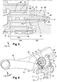
- FIG. 1 to 4 an arrangement for connecting a wheel to a motor vehicle (not shown).
- This arrangement 10 comprises a wheel knuckle 12 supporting a wheel rocket 14 and two connecting means 16, 18 to a vehicle structure member 20.
- the rocket wheel 14 and the two connecting means 16, 18 are disposed on a same substantially vertical axis "A" perpendicular to the longitudinal axis "L" of the vehicle.
- the arrangement 10 is intended to connect a wheel (not shown) via a wheel hub 22 to a structural element 19 of a motor vehicle.
- the structural element 19 is for example a plate which is fixed to an axle 20 of the vehicle.
- the axle 20 comprises a substantially longitudinal arm 24 connected to the vehicle body (not shown) at one end and to the connecting arrangement 10 at a second end opposite the first end.
- the axle 20 also comprises a deformable transverse cross member 26 integral with the respective arms 24 of two wheels.
- the structural element 19 is more particularly fixed to one of the arms 24.
- the wheel knuckle 12, the wheel rocket 14 and the two connecting means 16, 18 form a single subassembly to be mounted on the vehicle structure member 19.
- the rocket plate could alternatively be part of this subassembly. However, one could consider a mounting of the knuckle directly on the axle.
- the wheel knuckle 12 also includes fins 28 located in the upper part of the wheel knuckle 12 for fixing the brake calipers (not shown).
- the rocket wheel 14, with a transverse axis "B" is a tapered shaft inserted in a bore 30 of the wheel knuckle 12.
- the wheel spindle 14 supports tapered roller bearings 32 of the wheel hub 22 and has a threaded end 34 cooperating with an adjusting nut 36 for adjusting the tapered roller bearing 32.
- the wheel spindle 14 is therefore inserted in the bore 30 of the wheel hub 22 and the wheel (not shown) is thus rotatably mounted on the wheel rocket 14.
- a protective cover 38 may be disposed at one end of the bore 30 of the wheel hub 22 in order to prevent the penetration of pollutants in the bore 30 and in the tapered roller bearing 32.
- a sensor support 40 with axis "B" is arranged on the wheel knuckle 12.
- the sensor support 40 of generally circular shape, comprises a notch 42 intended to cooperate with a sensor 44 for rotating the wheel.
- the wheel knuckle 12 is pivotally mounted on the structural element 19 about a transverse axis "C” via the first connecting means 16.
- the axis "C” of pivoting is parallel to the axis "A" of rotation of the wheel.
- the pivot connection is made by a bearing 46, such as for example a tapered roller bearing supported by a transverse shaft 48 having a threaded end 50.
- the tapered roller bearing 46 comprises an inner ring 52, an outer ring 54 and one or two rows of conical rollers 56 arranged between the rings 52, 54.
- the outer ring 54 is mounted tightly in a bore 58, of axis "C", of the knuckle 12 of wheel, so that the knuckle 12 of wheel rotates around the "C" axis.
- the threaded end 50 of the transverse shaft 48 cooperates with a nut 60 and provides a fastening on the structural element 20.
- a protective cover 62 may be arranged at one end of the bore 58 of the knuckle 12 to prevent pollutants from entering the tapered roller bearing 46.
- the arrangement 10 also comprises a filtering means which limits in both directions the pivoting of the knuckle 12 about its axis "C".
- the filtration means is formed by the second connecting means 18. The filtering means thus allows the rocket carrier 12 to be resiliently returned to an intermediate angular position of rest while filtering the vibrations caused by rolling the wheels on the road.
- the filtration means is formed by a hydroelastic joint 63 of transverse axis "D". It comprises an outer ring 64 of axis "D” transversely offset vertically relative to the axis "C” of pivoting of the knuckle 12.
- the outer ring 64 is mounted tightly in a bore 66 of the knuckle 12. This bore 66 opens transversely vis-à-vis a vertical longitudinal face 68 of the structural element 19, said face 68 proximal, facing the wheel.
- the hydroelastic joint 63 also comprises an inner frame 70 made in one piece.
- the armature has the shape of a shaft extending along the axis "D" transversely coaxial with the axis of the outer ring 64.
- This inner frame 70 extends in part concentrically inside the outer ring 64.
- An annular filter member 72 here a hydroelastic member, is interposed radially between a portion 70A of articulation of the inner frame 70 and the outer ring 64.
- the filter member 72 comprises for example an elastic element and a pocket in which contains a damping liquid and a saturating element.
- the damping liquid is, for example, glycol in order to obtain a sufficient damping effect.
- the filtering means is formed by an elastic articulation.
- the filter member is an elastic member.
- the inner frame 70 having a substantially cylindrical portion 70B of reach which extends at least partially concentrically inside the member 72 of filtration.
- This reach section 70B extends transversely to the proximal face 68 of the structural element 19.
- the reach section 70B has a radial section of substantially constant dimensions. More particularly, this reach section 70B has a substantially cylindrical shape of revolution.
- the span portion 70B thus partially overlaps the articulation portion 70A of the inner frame 70.
- the reach section 70B extends over at least one third of the transverse length of the articulation portion 70A of the inner frame 70.
- the inner frame 70 is pivotable only about the axis "D" transverse to the filter member 72.
- the span portion 70B has more particularly a substantially circular contour section having the largest diameter of the portion 70A of articulation of the inner frame 70.
- the internal armature 70 further has a mounting section 70C which directly extends the reach section 70B transversely to the element 19 structure.
- the recess section 70C has a substantially frustoconical shape which extends from a wide end 74 which is arranged at the end of the reach section 70B to a narrow end 76.
- the wide end 74 of the recess section 70C has a radial section substantially identical to that of the reach section 70B.
- the inner frame 70 does not have a shoulder at the boundary between the embedding section 70C and the reach section 70B.
- This embedding section 70C is received transversely in a housing 78 of complementary shape which is formed in the proximal face 68 of the structural element 19.
- the housing 78 is thus delimited by a wall of frustoconical shape.
- the embedding section 70C is clamped transversely by fixing means against the inner wall of the housing 78. This allows a rigid and very strong fixation of the filtering means 18 on the structural element 19.
- the fastening means are formed by a screw 80 of transverse axis which is screwed into a central transverse tapping 82 of the mounting section 70C which opens into the narrow end 76.
- the threaded rod 84 of the screw 80 is inserted into a through hole 86 which is formed at the bottom of the housing 78 of the structural element 19.
- This orifice 86 is that which is coaxial with the axis "D" of the embedding section of the armature 70.
- the orifice 86 opens into a vertical longitudinal face 88 opposite to the housing 86 of the structural element 19, so-called distal face 88.
- a head 90 of the screw 80 is clamped against the distal face 88 in order to clamp, in reaction, the mounting section 70C against the inner wall of the housing 78.
- the fastening means are formed by a threaded rod which coaxially extends the narrow end of the embedding section.
- This threaded rod is for example made integral with the inner frame or screwed into a central thread.
- the threaded rod is inserted into the hole in the bottom of the housing.
- the threaded rod portion protruding from the distal face of the structural member receives a nut which provides the clamping effect of the embedding section against the inner wall of the housing.
- the filtering means 18 is disposed between the wheel spindle 14 and the first connecting means 16, so as to pivot the wheel knuckle 12 around the transverse axis "C” and to guide it in displacement on a longitudinal curve along arrow F illustrated at figure 1 , substantially in the longitudinal direction "L", in case of presence of an obstacle on the ground. Indeed, when the wheel encounters an obstacle on the ground, this wheel undergoes a force having a longitudinal and vertical component. The longitudinal component, along the "L" axis, applies directly to the wheel rocket 14, and generates a displacement of the wheel. This displacement of the wheel is called “wheel recoil". The wheel recoil, in the event of an obstacle, makes it possible to reduce the forces transmitted to the wheel train of the vehicle.
- the movement of the wheel rocket 14 has an oscillatory movement whose trajectory is an arc following the arrow F , centered on the transverse axis "C" of the filtration means 18.
- the bearing 46 of the pivot link 16 makes it possible to block the translations following all the "L”, “V” and “T” axes, as well as the rotations along the "L” and “V” axes, thus making it possible to adjust the camber wheels.
- Camber is the angle between the wheel and the plane perpendicular to the ground, along the axis "V". Adjusting the camber results in even tire wear.
- the rotation of the wheel knuckle 12 along the axis "C" is authorized by the pivot link 16 but its movement is limited by the filtering means 18, for example of an amplitude of about 10 mm, which allows to master the wheel recoil.
- the inner armature 70 only works in translation along a trajectory orthogonal to the transverse direction "T" with respect to the outer ring 64.
- the inner frame 70 undergoes substantially no pivotal movement relative to the outer ring 64.
- the internal frame 72 absorbs substantially all of the bending force applied by the wheel during an impact.
- the embedding of the inner frame 70 in the housing 78 of the structural element 19 made according to the arrangement of the invention advantageously allows to present a high resistance to breakage due to the shape of the embedding section and the shape of the span section.
- the large diameter of the reach section and the absence of shapes which can promote the concentration of stresses, such as shoulders, at the boundary between these two sections makes it possible to improve the breaking strength of the arrangement.
- the frustoconical shape of the embedding element facilitates the insertion of the embedding section in the housing, while ensuring a large contact surface for the transverse clamping of the inner frame against the housing. This allows in particular to promote a high rigidity of the connection between the inner frame and the structural element.
- the connecting device is easy to implement insofar as it is a pre-assembled subassembly. Such a subassembly is therefore adaptable to all types of axle.
Landscapes
- Engineering & Computer Science (AREA)
- Mechanical Engineering (AREA)
- Chemical & Material Sciences (AREA)
- Combustion & Propulsion (AREA)
- Transportation (AREA)
- Vehicle Body Suspensions (AREA)
- Steering-Linkage Mechanisms And Four-Wheel Steering (AREA)
Claims (8)
- Anordnung (10) zur Verbindung eines Achsschenkelträgers (12) mit einem Strukturelement (19) eines Kraftfahrzeugs, die aufweist:- einen Achsschenkelträger (12) eines Rads, der um eine erste Querachse (C) schwenkend auf das Strukturelement (19) montiert ist;- eine Filtereinrichtung (18), die das Schwenken des Achsschenkelträgers (12) in beiden Richtungen begrenzt und aufweist:- einen äußeren Ring (64) mit einer bezüglich der ersten Achse (C) senkrecht versetzten Querachse (D), wobei der äußere Ring (64) im Achsschenkelträger (12) gegenüber dem Strukturelement (19) untergebracht ist;- eine innere Armierung (70), die sich gemäß einer Querachse (D) koaxial zur Achse des äußeren Rings (64) erstreckt,- ein ringförmiges Filterorgan (72), das radial zwischen einen Gelenkteil (70A) der inneren Armierung (70) und den äußeren Ring (64) eingefügt ist;- wobei die innere Armierung (70) einen im Wesentlichen zylindrischen Auflagerabschnitt (70B) aufweist, der sich zumindest zum Teil konzentrisch im Inneren des Filterorgans (72) erstreckt und sich quer bis zum Strukturelement (19) erstreckt, indem er einen Radialschnitt mit im Wesentlichen konstanten Abmessungen aufweist;- Einrichtungen (80) zur Befestigung durch Quereinspannen der inneren Armierung (70) gegen das Strukturelement (19);
dadurch gekennzeichnet, dass die innere Armierung (70) einen Einbettungsteil (70C) von im Wesentlichen Kegelstumpfform aufweist, der sich von einem breiten Ende (74), das den Auflagerteil (70B) verlängert, bis zu einem schmalen Ende (76) erstreckt, wobei der Einbettungsabschnitt (70C) quer in einer komplementären Aufnahme (78) des Strukturelements (19) aufgenommen wird, gegen deren Innenwand der Einbettungsabschnitt (70C) durch die Befestigungseinrichtungen (80) quer eingespannt wird. - Anordnung nach dem vorhergehenden Anspruch, dadurch gekennzeichnet, dass das breite Ende (74) des Einbettungsabschnitts einen Radialschnitt im Wesentlichen gleich demjenigen des Auflagerabschnitts (70B) aufweist.
- Anordnung nach einem der vorhergehenden Ansprüche, dadurch gekennzeichnet, dass der Auflagerabschnitt (70B) einen im Wesentlichen kreisförmigen Umrissschnitt aufweist, der den größten Durchmesser des Gelenkteils (70A) der inneren Armierung (70) aufweist.
- Anordnung nach einem der vorhergehenden Ansprüche, dadurch gekennzeichnet, dass der Auflagerabschnitt (70B) sich über mindestens ein Drittel der Querlänge des Gelenkteils (70A) der inneren Armierung (70) erstreckt.
- Anordnung nach einem der vorhergehenden Ansprüche, dadurch gekennzeichnet, dass die Befestigungseinrichtungen von einer Gewindestange (84) gebildet werden, die in einer Durchgangsöffnung (86) aufgenommen wird, die am Boden der Aufnahme (78) des Strukturelements (19) hergestellt und koaxial zur Achse (D) des Einbettungsabschnitts (70C) ist.
- Anordnung nach dem vorhergehenden Anspruch, dadurch gekennzeichnet, dass die Gewindestange (84) zu einer Schraube (80) gehört, die in ein zentrales Querinnengewinde (82) des Einbettungsabschnitts (70C) geschraubt wird, das am schmalen Ende (76) mündet, wobei ein Kopf (90) gegen eine der Aufnahme entgegengesetzte Seite (88) des Strukturelements (19) aufliegt.
- Anordnung nach Anspruch 5, dadurch gekennzeichnet, dass die Gewindestange das schmale Ende des Einbettungsabschnitts koaxial verlängert, wobei eine Mutter am freien Ende der Gewindestange aufgenommen und in Auflage gegen eine der Aufnahme entgegengesetzte Seite des Strukturelements eingespannt wird.
- Anordnung nach dem vorhergehenden Anspruch, dadurch gekennzeichnet, dass die Gewindestange aus einem Stück mit dem inneren Armierung hergestellt wird.
Applications Claiming Priority (2)
| Application Number | Priority Date | Filing Date | Title |
|---|---|---|---|
| FR1559799A FR3042442B1 (fr) | 2015-10-15 | 2015-10-15 | "agencement pour la liaison d'un porte-fusee a un element de structure de vehicule automobile" |
| PCT/FR2016/052446 WO2017064382A1 (fr) | 2015-10-15 | 2016-09-27 | Agencement pour la liaison d'un porte fusée à un élément de structure de véhicule automobile |
Publications (2)
| Publication Number | Publication Date |
|---|---|
| EP3362304A1 EP3362304A1 (de) | 2018-08-22 |
| EP3362304B1 true EP3362304B1 (de) | 2019-07-10 |
Family
ID=55178141
Family Applications (1)
| Application Number | Title | Priority Date | Filing Date |
|---|---|---|---|
| EP16790635.3A Active EP3362304B1 (de) | 2015-10-15 | 2016-09-27 | Anordnung zur verbindung eines achsschenkels mit einem strukturelement eines kraftfahrzeugs |
Country Status (4)
| Country | Link |
|---|---|
| EP (1) | EP3362304B1 (de) |
| KR (1) | KR102550239B1 (de) |
| FR (1) | FR3042442B1 (de) |
| WO (1) | WO2017064382A1 (de) |
Family Cites Families (6)
| Publication number | Priority date | Publication date | Assignee | Title |
|---|---|---|---|---|
| FR2682326B1 (fr) * | 1991-10-15 | 1995-06-23 | Peugeot | Suspension notamment a bras tire pour vehicule automobile, avec systeme d'amortissement des chocs longitudinaux. |
| FR2698046B1 (fr) * | 1992-11-18 | 1995-01-13 | Maurice Moreau | Dispositif de suspension indépendante pour véhicule et véhicule muni d'un tel dispositif. |
| US6641229B1 (en) * | 2001-10-25 | 2003-11-04 | Hayes Lemmerz International, Inc. | Spindle mounting for aluminum wheel carrier |
| KR100452281B1 (ko) * | 2002-06-17 | 2004-10-12 | 현대모비스 주식회사 | 차량 현가장치의 크로스멤버용 부쉬 |
| ITTO20020553A1 (it) * | 2002-06-26 | 2003-12-29 | Fiat Ricerche | Dispositivo porta mozzo oscillante |
| FR2972389B1 (fr) * | 2011-03-11 | 2013-08-16 | Renault Sa | Dispositif de liaison d'une roue a une structure de vehicule automobile |
-
2015
- 2015-10-15 FR FR1559799A patent/FR3042442B1/fr not_active Expired - Fee Related
-
2016
- 2016-09-27 KR KR1020187013664A patent/KR102550239B1/ko active Active
- 2016-09-27 WO PCT/FR2016/052446 patent/WO2017064382A1/fr not_active Ceased
- 2016-09-27 EP EP16790635.3A patent/EP3362304B1/de active Active
Non-Patent Citations (1)
| Title |
|---|
| None * |
Also Published As
| Publication number | Publication date |
|---|---|
| KR102550239B1 (ko) | 2023-06-30 |
| WO2017064382A1 (fr) | 2017-04-20 |
| KR20180069033A (ko) | 2018-06-22 |
| FR3042442B1 (fr) | 2017-11-03 |
| EP3362304A1 (de) | 2018-08-22 |
| FR3042442A1 (fr) | 2017-04-21 |
Similar Documents
| Publication | Publication Date | Title |
|---|---|---|
| EP2683562B1 (de) | Vorrichtung zur befestigung eines fahrzeugrades an einer kraftfahrzeugstruktur | |
| EP2099627B1 (de) | Torsionselastische achse mit aktiver steuerung des lenkwinkels unter einsatz einer hydroelastischen verbindung | |
| EP1578626A1 (de) | Radträgervorrichtung mit dreifachscharnier, aufhängungsvorrichtung und kraftfahrzeug mit einer solchen trägervorrichtung | |
| EP0279135B1 (de) | Aufhängungs- und Schwenkvorrichtung von einem lenkbaren Rad eines Kraftfahrzeuges | |
| EP1765615A1 (de) | Kraftfahrzeugfederungsvorrichtung | |
| FR2707926A1 (fr) | Dispositif de suspension perfectionné pour une roue avant de véhicule automobile. | |
| EP0538116A1 (de) | Aufhängung, insbesondere mit gezogenen Lenkern für Kraftfahrzeug, mit einem Dämpfungssystem für längsgerichtete Stösse | |
| FR3018763A1 (fr) | Structure arriere de vehicule automobile | |
| EP1673244A2 (de) | Kraftfahrzeuglenkachse | |
| WO2017064382A1 (fr) | Agencement pour la liaison d'un porte fusée à un élément de structure de véhicule automobile | |
| WO2012175844A1 (fr) | Bras de suspension de vehicule | |
| EP3215377B1 (de) | Nabenträger für eine verbundlenkerachse | |
| FR2750925A1 (fr) | Suspension horizontale pour roue de vehicule automobile avec systeme de filtrage des chocs longitudinaux | |
| FR3055878A1 (fr) | Train arriere d'un vehicule, notamment automobile | |
| WO2021255649A1 (fr) | Dispositif interne de colonne de direction a roulement excentrique | |
| EP3317131B1 (de) | Aufhängungsvorrichtung für ein kraftfahrzeugrad mit einem lenker mit einem blechkörper und einem daran befestigten massiven kopf | |
| EP4347282B1 (de) | Hinterachse für ein kraftfahrzeug mit zwei hinteren längslenkern mit verbessertem elastischem verhalten | |
| EP0253708B1 (de) | Hinterachse mit passiver Wirkung für Kraftfahrzeuge und Kraftfahrzeuge, ausgerüstet mit solch einer Hinterachse | |
| FR3096338A1 (fr) | Amortisseur pour vehicule automobile ou motocyclette | |
| FR2701674A1 (fr) | Suspension à barre de torsion et à filtrage des vibrations pour roue, notamment arrière, de véhicule automobile. | |
| EP4134255A1 (de) | Hinterachse eines kraftfahrzeugs, insbesondere mit gelenkten rädern | |
| FR3099089A1 (fr) | Palier et pièce de réglage pour train multi-bras | |
| FR2701236A1 (fr) | Suspension à bras tiré et filtrage des chocs longitudinaux, notamment pour une roue arrière de véhicule automobile. | |
| FR2848913A1 (fr) | Procede et dispositif d'amelioration de la tenue de route de vehicules automobiles par reequilibrage des charges en virage | |
| FR2710008A1 (fr) | Train avant perfectionné pour véhicule automobile. |
Legal Events
| Date | Code | Title | Description |
|---|---|---|---|
| STAA | Information on the status of an ep patent application or granted ep patent |
Free format text: STATUS: UNKNOWN |
|
| STAA | Information on the status of an ep patent application or granted ep patent |
Free format text: STATUS: THE INTERNATIONAL PUBLICATION HAS BEEN MADE |
|
| PUAI | Public reference made under article 153(3) epc to a published international application that has entered the european phase |
Free format text: ORIGINAL CODE: 0009012 |
|
| STAA | Information on the status of an ep patent application or granted ep patent |
Free format text: STATUS: REQUEST FOR EXAMINATION WAS MADE |
|
| 17P | Request for examination filed |
Effective date: 20180503 |
|
| AK | Designated contracting states |
Kind code of ref document: A1 Designated state(s): AL AT BE BG CH CY CZ DE DK EE ES FI FR GB GR HR HU IE IS IT LI LT LU LV MC MK MT NL NO PL PT RO RS SE SI SK SM TR |
|
| AX | Request for extension of the european patent |
Extension state: BA ME |
|
| DAV | Request for validation of the european patent (deleted) | ||
| DAX | Request for extension of the european patent (deleted) | ||
| GRAP | Despatch of communication of intention to grant a patent |
Free format text: ORIGINAL CODE: EPIDOSNIGR1 |
|
| STAA | Information on the status of an ep patent application or granted ep patent |
Free format text: STATUS: GRANT OF PATENT IS INTENDED |
|
| INTG | Intention to grant announced |
Effective date: 20190208 |
|
| GRAS | Grant fee paid |
Free format text: ORIGINAL CODE: EPIDOSNIGR3 |
|
| GRAA | (expected) grant |
Free format text: ORIGINAL CODE: 0009210 |
|
| STAA | Information on the status of an ep patent application or granted ep patent |
Free format text: STATUS: THE PATENT HAS BEEN GRANTED |
|
| AK | Designated contracting states |
Kind code of ref document: B1 Designated state(s): AL AT BE BG CH CY CZ DE DK EE ES FI FR GB GR HR HU IE IS IT LI LT LU LV MC MK MT NL NO PL PT RO RS SE SI SK SM TR |
|
| REG | Reference to a national code |
Ref country code: GB Ref legal event code: FG4D Free format text: NOT ENGLISH |
|
| REG | Reference to a national code |
Ref country code: CH Ref legal event code: EP Ref country code: AT Ref legal event code: REF Ref document number: 1153164 Country of ref document: AT Kind code of ref document: T Effective date: 20190715 |
|
| REG | Reference to a national code |
Ref country code: DE Ref legal event code: R096 Ref document number: 602016016806 Country of ref document: DE |
|
| REG | Reference to a national code |
Ref country code: IE Ref legal event code: FG4D Free format text: LANGUAGE OF EP DOCUMENT: FRENCH |
|
| REG | Reference to a national code |
Ref country code: NL Ref legal event code: MP Effective date: 20190710 |
|
| REG | Reference to a national code |
Ref country code: LT Ref legal event code: MG4D |
|
| REG | Reference to a national code |
Ref country code: AT Ref legal event code: MK05 Ref document number: 1153164 Country of ref document: AT Kind code of ref document: T Effective date: 20190710 |
|
| PG25 | Lapsed in a contracting state [announced via postgrant information from national office to epo] |
Ref country code: FI Free format text: LAPSE BECAUSE OF FAILURE TO SUBMIT A TRANSLATION OF THE DESCRIPTION OR TO PAY THE FEE WITHIN THE PRESCRIBED TIME-LIMIT Effective date: 20190710 Ref country code: AT Free format text: LAPSE BECAUSE OF FAILURE TO SUBMIT A TRANSLATION OF THE DESCRIPTION OR TO PAY THE FEE WITHIN THE PRESCRIBED TIME-LIMIT Effective date: 20190710 Ref country code: NO Free format text: LAPSE BECAUSE OF FAILURE TO SUBMIT A TRANSLATION OF THE DESCRIPTION OR TO PAY THE FEE WITHIN THE PRESCRIBED TIME-LIMIT Effective date: 20191010 Ref country code: BG Free format text: LAPSE BECAUSE OF FAILURE TO SUBMIT A TRANSLATION OF THE DESCRIPTION OR TO PAY THE FEE WITHIN THE PRESCRIBED TIME-LIMIT Effective date: 20191010 Ref country code: SE Free format text: LAPSE BECAUSE OF FAILURE TO SUBMIT A TRANSLATION OF THE DESCRIPTION OR TO PAY THE FEE WITHIN THE PRESCRIBED TIME-LIMIT Effective date: 20190710 Ref country code: PT Free format text: LAPSE BECAUSE OF FAILURE TO SUBMIT A TRANSLATION OF THE DESCRIPTION OR TO PAY THE FEE WITHIN THE PRESCRIBED TIME-LIMIT Effective date: 20191111 Ref country code: LT Free format text: LAPSE BECAUSE OF FAILURE TO SUBMIT A TRANSLATION OF THE DESCRIPTION OR TO PAY THE FEE WITHIN THE PRESCRIBED TIME-LIMIT Effective date: 20190710 Ref country code: NL Free format text: LAPSE BECAUSE OF FAILURE TO SUBMIT A TRANSLATION OF THE DESCRIPTION OR TO PAY THE FEE WITHIN THE PRESCRIBED TIME-LIMIT Effective date: 20190710 Ref country code: HR Free format text: LAPSE BECAUSE OF FAILURE TO SUBMIT A TRANSLATION OF THE DESCRIPTION OR TO PAY THE FEE WITHIN THE PRESCRIBED TIME-LIMIT Effective date: 20190710 |
|
| PG25 | Lapsed in a contracting state [announced via postgrant information from national office to epo] |
Ref country code: IS Free format text: LAPSE BECAUSE OF FAILURE TO SUBMIT A TRANSLATION OF THE DESCRIPTION OR TO PAY THE FEE WITHIN THE PRESCRIBED TIME-LIMIT Effective date: 20191110 Ref country code: RS Free format text: LAPSE BECAUSE OF FAILURE TO SUBMIT A TRANSLATION OF THE DESCRIPTION OR TO PAY THE FEE WITHIN THE PRESCRIBED TIME-LIMIT Effective date: 20190710 Ref country code: LV Free format text: LAPSE BECAUSE OF FAILURE TO SUBMIT A TRANSLATION OF THE DESCRIPTION OR TO PAY THE FEE WITHIN THE PRESCRIBED TIME-LIMIT Effective date: 20190710 Ref country code: AL Free format text: LAPSE BECAUSE OF FAILURE TO SUBMIT A TRANSLATION OF THE DESCRIPTION OR TO PAY THE FEE WITHIN THE PRESCRIBED TIME-LIMIT Effective date: 20190710 Ref country code: ES Free format text: LAPSE BECAUSE OF FAILURE TO SUBMIT A TRANSLATION OF THE DESCRIPTION OR TO PAY THE FEE WITHIN THE PRESCRIBED TIME-LIMIT Effective date: 20190710 Ref country code: GR Free format text: LAPSE BECAUSE OF FAILURE TO SUBMIT A TRANSLATION OF THE DESCRIPTION OR TO PAY THE FEE WITHIN THE PRESCRIBED TIME-LIMIT Effective date: 20191011 |
|
| PG25 | Lapsed in a contracting state [announced via postgrant information from national office to epo] |
Ref country code: TR Free format text: LAPSE BECAUSE OF FAILURE TO SUBMIT A TRANSLATION OF THE DESCRIPTION OR TO PAY THE FEE WITHIN THE PRESCRIBED TIME-LIMIT Effective date: 20190710 |
|
| PG25 | Lapsed in a contracting state [announced via postgrant information from national office to epo] |
Ref country code: EE Free format text: LAPSE BECAUSE OF FAILURE TO SUBMIT A TRANSLATION OF THE DESCRIPTION OR TO PAY THE FEE WITHIN THE PRESCRIBED TIME-LIMIT Effective date: 20190710 Ref country code: PL Free format text: LAPSE BECAUSE OF FAILURE TO SUBMIT A TRANSLATION OF THE DESCRIPTION OR TO PAY THE FEE WITHIN THE PRESCRIBED TIME-LIMIT Effective date: 20190710 Ref country code: DK Free format text: LAPSE BECAUSE OF FAILURE TO SUBMIT A TRANSLATION OF THE DESCRIPTION OR TO PAY THE FEE WITHIN THE PRESCRIBED TIME-LIMIT Effective date: 20190710 Ref country code: RO Free format text: LAPSE BECAUSE OF FAILURE TO SUBMIT A TRANSLATION OF THE DESCRIPTION OR TO PAY THE FEE WITHIN THE PRESCRIBED TIME-LIMIT Effective date: 20190710 Ref country code: IT Free format text: LAPSE BECAUSE OF FAILURE TO SUBMIT A TRANSLATION OF THE DESCRIPTION OR TO PAY THE FEE WITHIN THE PRESCRIBED TIME-LIMIT Effective date: 20190710 |
|
| PG25 | Lapsed in a contracting state [announced via postgrant information from national office to epo] |
Ref country code: SM Free format text: LAPSE BECAUSE OF FAILURE TO SUBMIT A TRANSLATION OF THE DESCRIPTION OR TO PAY THE FEE WITHIN THE PRESCRIBED TIME-LIMIT Effective date: 20190710 Ref country code: CZ Free format text: LAPSE BECAUSE OF FAILURE TO SUBMIT A TRANSLATION OF THE DESCRIPTION OR TO PAY THE FEE WITHIN THE PRESCRIBED TIME-LIMIT Effective date: 20190710 Ref country code: MC Free format text: LAPSE BECAUSE OF FAILURE TO SUBMIT A TRANSLATION OF THE DESCRIPTION OR TO PAY THE FEE WITHIN THE PRESCRIBED TIME-LIMIT Effective date: 20190710 Ref country code: IS Free format text: LAPSE BECAUSE OF FAILURE TO SUBMIT A TRANSLATION OF THE DESCRIPTION OR TO PAY THE FEE WITHIN THE PRESCRIBED TIME-LIMIT Effective date: 20200224 Ref country code: SK Free format text: LAPSE BECAUSE OF FAILURE TO SUBMIT A TRANSLATION OF THE DESCRIPTION OR TO PAY THE FEE WITHIN THE PRESCRIBED TIME-LIMIT Effective date: 20190710 |
|
| REG | Reference to a national code |
Ref country code: CH Ref legal event code: PL |
|
| REG | Reference to a national code |
Ref country code: DE Ref legal event code: R097 Ref document number: 602016016806 Country of ref document: DE |
|
| PLBE | No opposition filed within time limit |
Free format text: ORIGINAL CODE: 0009261 |
|
| STAA | Information on the status of an ep patent application or granted ep patent |
Free format text: STATUS: NO OPPOSITION FILED WITHIN TIME LIMIT |
|
| PG2D | Information on lapse in contracting state deleted |
Ref country code: IS |
|
| PG25 | Lapsed in a contracting state [announced via postgrant information from national office to epo] |
Ref country code: IE Free format text: LAPSE BECAUSE OF NON-PAYMENT OF DUE FEES Effective date: 20190927 Ref country code: LU Free format text: LAPSE BECAUSE OF NON-PAYMENT OF DUE FEES Effective date: 20190927 Ref country code: LI Free format text: LAPSE BECAUSE OF NON-PAYMENT OF DUE FEES Effective date: 20190930 Ref country code: CH Free format text: LAPSE BECAUSE OF NON-PAYMENT OF DUE FEES Effective date: 20190930 |
|
| REG | Reference to a national code |
Ref country code: BE Ref legal event code: MM Effective date: 20190930 |
|
| 26N | No opposition filed |
Effective date: 20200603 |
|
| PG25 | Lapsed in a contracting state [announced via postgrant information from national office to epo] |
Ref country code: SI Free format text: LAPSE BECAUSE OF FAILURE TO SUBMIT A TRANSLATION OF THE DESCRIPTION OR TO PAY THE FEE WITHIN THE PRESCRIBED TIME-LIMIT Effective date: 20190710 Ref country code: BE Free format text: LAPSE BECAUSE OF NON-PAYMENT OF DUE FEES Effective date: 20190930 |
|
| PG25 | Lapsed in a contracting state [announced via postgrant information from national office to epo] |
Ref country code: CY Free format text: LAPSE BECAUSE OF FAILURE TO SUBMIT A TRANSLATION OF THE DESCRIPTION OR TO PAY THE FEE WITHIN THE PRESCRIBED TIME-LIMIT Effective date: 20190710 |
|
| PG25 | Lapsed in a contracting state [announced via postgrant information from national office to epo] |
Ref country code: HU Free format text: LAPSE BECAUSE OF FAILURE TO SUBMIT A TRANSLATION OF THE DESCRIPTION OR TO PAY THE FEE WITHIN THE PRESCRIBED TIME-LIMIT; INVALID AB INITIO Effective date: 20160927 Ref country code: MT Free format text: LAPSE BECAUSE OF FAILURE TO SUBMIT A TRANSLATION OF THE DESCRIPTION OR TO PAY THE FEE WITHIN THE PRESCRIBED TIME-LIMIT Effective date: 20190710 |
|
| PG25 | Lapsed in a contracting state [announced via postgrant information from national office to epo] |
Ref country code: MK Free format text: LAPSE BECAUSE OF FAILURE TO SUBMIT A TRANSLATION OF THE DESCRIPTION OR TO PAY THE FEE WITHIN THE PRESCRIBED TIME-LIMIT Effective date: 20190710 |
|
| P01 | Opt-out of the competence of the unified patent court (upc) registered |
Effective date: 20230608 |
|
| PGFP | Annual fee paid to national office [announced via postgrant information from national office to epo] |
Ref country code: DE Payment date: 20250919 Year of fee payment: 10 |
|
| PGFP | Annual fee paid to national office [announced via postgrant information from national office to epo] |
Ref country code: GB Payment date: 20250919 Year of fee payment: 10 |
|
| PGFP | Annual fee paid to national office [announced via postgrant information from national office to epo] |
Ref country code: FR Payment date: 20250922 Year of fee payment: 10 |