EP3363202B1 - Appareils et procédés permettant de coder et de décoder des images - Google Patents
Appareils et procédés permettant de coder et de décoder des images Download PDFInfo
- Publication number
- EP3363202B1 EP3363202B1 EP16791692.3A EP16791692A EP3363202B1 EP 3363202 B1 EP3363202 B1 EP 3363202B1 EP 16791692 A EP16791692 A EP 16791692A EP 3363202 B1 EP3363202 B1 EP 3363202B1
- Authority
- EP
- European Patent Office
- Prior art keywords
- image
- rotation angle
- transform
- basis
- rotated
- Prior art date
- Legal status (The legal status is an assumption and is not a legal conclusion. Google has not performed a legal analysis and makes no representation as to the accuracy of the status listed.)
- Active
Links
Images










Classifications
-
- H—ELECTRICITY
- H04—ELECTRIC COMMUNICATION TECHNIQUE
- H04N—PICTORIAL COMMUNICATION, e.g. TELEVISION
- H04N1/00—Scanning, transmission or reproduction of documents or the like, e.g. facsimile transmission; Details thereof
- H04N1/41—Bandwidth or redundancy reduction
-
- G—PHYSICS
- G06—COMPUTING OR CALCULATING; COUNTING
- G06F—ELECTRIC DIGITAL DATA PROCESSING
- G06F18/00—Pattern recognition
- G06F18/20—Analysing
- G06F18/21—Design or setup of recognition systems or techniques; Extraction of features in feature space; Blind source separation
- G06F18/213—Feature extraction, e.g. by transforming the feature space; Summarisation; Mappings, e.g. subspace methods
- G06F18/2135—Feature extraction, e.g. by transforming the feature space; Summarisation; Mappings, e.g. subspace methods based on approximation criteria, e.g. principal component analysis
-
- H—ELECTRICITY
- H04—ELECTRIC COMMUNICATION TECHNIQUE
- H04N—PICTORIAL COMMUNICATION, e.g. TELEVISION
- H04N19/00—Methods or arrangements for coding, decoding, compressing or decompressing digital video signals
- H04N19/10—Methods or arrangements for coding, decoding, compressing or decompressing digital video signals using adaptive coding
- H04N19/102—Methods or arrangements for coding, decoding, compressing or decompressing digital video signals using adaptive coding characterised by the element, parameter or selection affected or controlled by the adaptive coding
- H04N19/12—Selection from among a plurality of transforms or standards, e.g. selection between discrete cosine transform [DCT] and sub-band transform or selection between H.263 and H.264
-
- H—ELECTRICITY
- H04—ELECTRIC COMMUNICATION TECHNIQUE
- H04N—PICTORIAL COMMUNICATION, e.g. TELEVISION
- H04N19/00—Methods or arrangements for coding, decoding, compressing or decompressing digital video signals
- H04N19/10—Methods or arrangements for coding, decoding, compressing or decompressing digital video signals using adaptive coding
- H04N19/102—Methods or arrangements for coding, decoding, compressing or decompressing digital video signals using adaptive coding characterised by the element, parameter or selection affected or controlled by the adaptive coding
- H04N19/12—Selection from among a plurality of transforms or standards, e.g. selection between discrete cosine transform [DCT] and sub-band transform or selection between H.263 and H.264
- H04N19/122—Selection of transform size, e.g. 8x8 or 2x4x8 DCT; Selection of sub-band transforms of varying structure or type
-
- H—ELECTRICITY
- H04—ELECTRIC COMMUNICATION TECHNIQUE
- H04N—PICTORIAL COMMUNICATION, e.g. TELEVISION
- H04N19/00—Methods or arrangements for coding, decoding, compressing or decompressing digital video signals
- H04N19/10—Methods or arrangements for coding, decoding, compressing or decompressing digital video signals using adaptive coding
- H04N19/134—Methods or arrangements for coding, decoding, compressing or decompressing digital video signals using adaptive coding characterised by the element, parameter or criterion affecting or controlling the adaptive coding
- H04N19/136—Incoming video signal characteristics or properties
- H04N19/137—Motion inside a coding unit, e.g. average field, frame or block difference
- H04N19/139—Analysis of motion vectors, e.g. their magnitude, direction, variance or reliability
-
- H—ELECTRICITY
- H04—ELECTRIC COMMUNICATION TECHNIQUE
- H04N—PICTORIAL COMMUNICATION, e.g. TELEVISION
- H04N19/00—Methods or arrangements for coding, decoding, compressing or decompressing digital video signals
- H04N19/10—Methods or arrangements for coding, decoding, compressing or decompressing digital video signals using adaptive coding
- H04N19/134—Methods or arrangements for coding, decoding, compressing or decompressing digital video signals using adaptive coding characterised by the element, parameter or criterion affecting or controlling the adaptive coding
- H04N19/146—Data rate or code amount at the encoder output
- H04N19/147—Data rate or code amount at the encoder output according to rate distortion criteria
-
- H—ELECTRICITY
- H04—ELECTRIC COMMUNICATION TECHNIQUE
- H04N—PICTORIAL COMMUNICATION, e.g. TELEVISION
- H04N19/00—Methods or arrangements for coding, decoding, compressing or decompressing digital video signals
- H04N19/10—Methods or arrangements for coding, decoding, compressing or decompressing digital video signals using adaptive coding
- H04N19/169—Methods or arrangements for coding, decoding, compressing or decompressing digital video signals using adaptive coding characterised by the coding unit, i.e. the structural portion or semantic portion of the video signal being the object or the subject of the adaptive coding
- H04N19/17—Methods or arrangements for coding, decoding, compressing or decompressing digital video signals using adaptive coding characterised by the coding unit, i.e. the structural portion or semantic portion of the video signal being the object or the subject of the adaptive coding the unit being an image region, e.g. an object
- H04N19/176—Methods or arrangements for coding, decoding, compressing or decompressing digital video signals using adaptive coding characterised by the coding unit, i.e. the structural portion or semantic portion of the video signal being the object or the subject of the adaptive coding the unit being an image region, e.g. an object the region being a block, e.g. a macroblock
-
- H—ELECTRICITY
- H04—ELECTRIC COMMUNICATION TECHNIQUE
- H04N—PICTORIAL COMMUNICATION, e.g. TELEVISION
- H04N19/00—Methods or arrangements for coding, decoding, compressing or decompressing digital video signals
- H04N19/10—Methods or arrangements for coding, decoding, compressing or decompressing digital video signals using adaptive coding
- H04N19/169—Methods or arrangements for coding, decoding, compressing or decompressing digital video signals using adaptive coding characterised by the coding unit, i.e. the structural portion or semantic portion of the video signal being the object or the subject of the adaptive coding
- H04N19/18—Methods or arrangements for coding, decoding, compressing or decompressing digital video signals using adaptive coding characterised by the coding unit, i.e. the structural portion or semantic portion of the video signal being the object or the subject of the adaptive coding the unit being a set of transform coefficients
-
- H—ELECTRICITY
- H04—ELECTRIC COMMUNICATION TECHNIQUE
- H04N—PICTORIAL COMMUNICATION, e.g. TELEVISION
- H04N19/00—Methods or arrangements for coding, decoding, compressing or decompressing digital video signals
- H04N19/10—Methods or arrangements for coding, decoding, compressing or decompressing digital video signals using adaptive coding
- H04N19/189—Methods or arrangements for coding, decoding, compressing or decompressing digital video signals using adaptive coding characterised by the adaptation method, adaptation tool or adaptation type used for the adaptive coding
- H04N19/196—Methods or arrangements for coding, decoding, compressing or decompressing digital video signals using adaptive coding characterised by the adaptation method, adaptation tool or adaptation type used for the adaptive coding being specially adapted for the computation of encoding parameters, e.g. by averaging previously computed encoding parameters
-
- H—ELECTRICITY
- H04—ELECTRIC COMMUNICATION TECHNIQUE
- H04N—PICTORIAL COMMUNICATION, e.g. TELEVISION
- H04N19/00—Methods or arrangements for coding, decoding, compressing or decompressing digital video signals
- H04N19/60—Methods or arrangements for coding, decoding, compressing or decompressing digital video signals using transform coding
- H04N19/625—Methods or arrangements for coding, decoding, compressing or decompressing digital video signals using transform coding using discrete cosine transform [DCT]
-
- H—ELECTRICITY
- H04—ELECTRIC COMMUNICATION TECHNIQUE
- H04N—PICTORIAL COMMUNICATION, e.g. TELEVISION
- H04N19/00—Methods or arrangements for coding, decoding, compressing or decompressing digital video signals
- H04N19/60—Methods or arrangements for coding, decoding, compressing or decompressing digital video signals using transform coding
- H04N19/61—Methods or arrangements for coding, decoding, compressing or decompressing digital video signals using transform coding in combination with predictive coding
Definitions
- the present invention relates to a method and an apparatus for encoding and/or decoding digital images or video streams; particularly, an apparatus and method for compressing and decompressing digital images or video streams by means of the so-called Steerable Discrete Cosine Transform (SDCT) is described.
- SDCT Steerable Discrete Cosine Transform
- the 2D Discrete Cosine Transform is the most common transform used for block-based image and video compression; being at the basis of popular video coding standards such as MPEG-2 (used, for example, for terrestrial and satellite standard definition video broadcasting and in the DVD storage format), H.264/AVC (used for high-definition video broadcasting, streaming over IP networks and in Blu-Ray discs) and in the recently standardized H.265/HEVC (expected to replace H.264/AVC in the above-mentioned scenarios).
- Any DCT transform comprises one so called DC (Direct Current) component or basis function which contains the constant valued basis function and AC (Alternate Current) components, which contain the high frequencies spectral components of the image, i.e. the details.
- the image is subdivided into pixel (or sample) blocks having a square shape and then the DCT is applied to each block (possibly adapting the size of the block to the image characteristics), which is then independently encoded and decoded in the simplest case (more advanced compression schemes may include intra and inter-frame block prediction to further improve the codec performance).
- the DCT separates the image into parts (or spectral sub-bands) of differing importance with respect to the image visual quality.
- Each 2D Discrete Cosine Transform acting on a square block or matrix of N ⁇ N input samples of a bidimensional signal uses a set of real basis vectors whose components are cosines.
- Each DCT basis contains the eigenvectors of a symmetric "second difference" matrix (see for example G. Strang SIAM review, vol. 41, no. 1, pp. 135-147, 1999 ).
- the actual ability of the DCT to compact the energy of a signal depends on the semantics of the particular image or image block to be encoded.
- the values resulting from the transform are generally called coefficients, or transformed coefficients.
- the 2D DCT is composed of two separable 1D (one-dimensional) transforms along the vertical and horizontal directions, thus applied to each row and column of the considered block. For this reason, images dominated by horizontal and vertical patterns are desirable and can be efficiently represented by this conventional DCT.
- a Directional DCT is the first attempt in this sense in which the first 1D DCT may choose to follow a direction other than the vertical or horizontal one, then the coefficients produced by all directional transforms in the first step are rearranged so that the second transform can be applied to the coefficients that are best aligned with each other (see B. Zeng and J. Fu, "Directional discrete cosine transforms - a new framework for image coding," Circuits and Systems for Video Technology, IEEE Transactions on, vol. 18, no. 3, pp. 305-313, 2008 ).
- this method faces several issues: 1D DCTs of various lengths are needed, some of them are very short and their lengths are not always a power of two.
- the second DCT may not always be applied to coefficients of similar AC frequencies.
- MDDT Mode-Dependent Directional Transform
- KLT Karhunen-Loeve transform
- Several variations and enhancement of MDDT have been suggested which exploit symmetry to reduce the number of transform matrices needed (see M. Budagavi and M. Zhou, “Orthogonal MDDT and mode dependent DCT,” ITU-T Q, vol.
- each image can be represented as a combination of nodes and edges, where each pixel is a node and the edges describe the connectivity region among the pixels (see D. Shuman, S. Narang, P. Frossard, A. Ortega, and P. Vandergheynst, "The emerging field of signal processing on graphs: Extending highdimensional data analysis to networks and other irregular domains," Signal Processing Magazine, IEEE, vol. 30, no. 3, pp. 83-98, 2013 ).
- This graph representation allows one to design a discontinuity-aware transform in an elegant and effective way.
- U.S. Patent Application No. US 2011/135212 A1 to SAMSUNG ELECTRONICS discloses a method and apparatus for encoding and decoding an image by using a DCT transform that is modified through a simple permutation ("partial switch") of one or more of its coefficients.
- Block-based separable transforms tend to be inefficient when blocks contain arbitrarily shaped discontinuities.
- transforms incorporating directional information have been explored as an appealing alternative.
- the present invention aims at solving this problem by providing a method and an apparatus for encoding and/or decoding digital images according to claims 1, 10, 16 and 17, based on a new directional transform, the so called Steerable Discrete Cosine Transform (SDCT).
- SDCT Steerable Discrete Cosine Transform
- the SDCT is obtained modifying the orientation of the 2D DCT basis.
- SDCT enables precise matching of directionality in each image block by determining a rotation angle, in order to optimize the coding performance of the entire encoding and decoding system.
- the proposed coding chain provides a significant performance gain when compared to the conventional DCT.
- the mathematical framework on which the steerable DCT is based allows to generalize the transform to more complex steering patterns than a single pure rotation.
- any reference to "an embodiment” will indicate that a particular configuration, structure or feature described concerning the implementation of the invention is comprised in at least one embodiment. Therefore, the phrase “in an embodiment” and other similar phrases, which may be present in different parts of this description, will not necessarily be all related to the same embodiment. Furthermore, any particular configuration, structure or feature may be combined in one or more embodiments in any way deemed appropriate. The references below are therefore used only for simplicity's sake, and do not limit the protection scope or extension of the various embodiments.
- Fig. 1 shows a typical encoding/decoding process for digital images. It should be noted that many other operations may be performed into the encoder 100 and the decoder 110, however the present description aims at depicting only the main units of an image coding apparatus in an exemplificative manner.
- an encoding apparatus 100 for compressing digital images based on hybrid video coding basically comprises a transform unit 101, a quantizer 102 and an entropy coder (or encoder) 103.
- the transform unit 101 takes as input the image or block image to be coded and converts it to a frequency domain using a specific transform.
- the unit transform is commonly represented by the Discrete Cosine Transform in common image standards like JPEG.
- the Discrete Cosine Transform (DCT) represents an image as a sum of sinusoids of varying magnitudes and frequencies. It aims at representing the original sample of a signal, an image for example, in a more efficient way by concentrating the visually significant information in just a few coefficients such that the transformed parameters require fewer bits to be coded.
- 2-D DCT (or 2D-DCT, or simply DCT) can be computed in two steps by successive 1-D operations on rows and columns of an image, using the separability principle. It operates on an image f, a block of N ⁇ N samples, typically image samples (or residual values after prediction in the space and/or time domain).
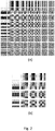
- the output of a 2-dimensional DCT is a set of N ⁇ N coefficients representing the image block data in the DCT domain which can be considered as "weights" of a set of standard basis patterns (i.e. weights applied to each basis pattern), often referred to as basis functions of the DCT.
- Horizontal frequencies increase from left to right, and vertical frequencies increase from top to bottom.
- the constant-valued basis function at the upper left is often called the DC basis function, and the corresponding DCT coefficient is often called in literature the DC coefficient.
- the other basis functions exhibit a progressive increase in frequency both in the vertical and horizontal direction.
- the present invention replaces this phase with the new Steerable Discrete Cosine Transform as described later on in Fig. 8 .
- the transformed coefficients have some features that enable efficient compression in the following stages.
- the quantizer 102 reduces the input range values into a smaller set.
- the quantizer unit exploits the low sensitiveness of the HVS (Human Visual System) towards high frequencies.
- HVS Human Visual System
- the amount of information in the high frequency components is reduced in this phase, sometimes rounded to zero, depending on their position with regard to the quantization matrix.
- This step could be lossy or lossless regarding the selected type of quantization.
- the quantized coefficients are passed to unit 103 before being sent to the channel or memorization unit.
- the entropy coding unit 103 rearranges the samples in an efficient way (e.g. a zig-zag scan reading) reduces the number of bit needed to code a symbol.
- Typical entropy coding techniques are, for example, Huffman coding or arithmetic coding like CABAC or CAVLC.
- an image decoding apparatus 110 based on hybrid video decoding mainly comprises the following units: an entropy decoder 113, a dequantizer 112 and an inverse transform unit 111.
- the entropy decoder 113 converts the input bit stream comprising the encoded and quantized image coefficients into the quantized coefficients.
- the dequantizer 112 performs the inverse process of unit quantizer 102 by reconstructing the values of the coefficients to be passed to the final main stage.
- the inverse transform unit 111 takes as input the de-quantized coefficients and reconstructs back the output of the image signal (the so called samples or pixel values) into the spatial domain.
- the inverse transform unit is commonly represented by the inverse of the DCT, the Inverse Discrete Cosine Transform (IDCT or type-III DCT).
- the present invention discloses an apparatus based on a new directional transform, the Steerable Discrete Cosine Transform or SDCT, described in details in the following.
- the SDCT improves the conventional DCT by keeping into account the directional information of each image block, thus adapting the encoding to the specific semantic of the current samples block.
- Fig. 8 illustrates an exemplary reference image encoder and decoder pair based on the Steerable Discrete Cosine Transform, wherein said encoder is fed with an image f or an image block containing raw data in any format (for example RGB, YUV, and so on).
- the encoder device 11 comprises the following parts:
- the processing means 1100 can also be described in structural way, i.e. they can comprise a transform unit 1101, here represented by the new SDCT transform unit, a quantizer 1102 and an entropy coder 1103.
- a transform unit 1101 here represented by the new SDCT transform unit
- a quantizer 1102 and an entropy coder 1103.
- the Discrete Cosine Transform cannot represent in an effective way discontinuities of the image not following a certain horizontal or vertical direction. This problem can be solved by applying to the conventional image or video coding some elements pertaining to the graph theory.
- a graph-based transform can be seen as a generalization of the previously described block-based transform (or, conversely, the block based transform can be considered a special case of a graph-based transform).
- the image (or any subset thereof) can be represented as a graph G of nodes or vertices V connected by edges E: each node or vertex represents a pixel of the image and each edge between two nodes describes the adjacency between the pixels: an edge connecting two pixels indicates that they are adjacent horizontally or vertically.
- the 1D DCT basis is the unique eigenbasis for the Laplacian of a graph path P n , i.e. the graph transform for a signal (an image, for example) represented by a path graph is equivalent to the 1D-DCT transform.
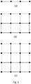
- a two-dimensional grid graph G mn can be seen as the Cartesian product of two path graphs P n and P m on n and m vertices, respectively (see Fig. 3-b ).
- the product of the two graphs P n is a square grid graph (see Fig. 3-c ).
- the dimension of the eigenspaces for the pair of eigenvalues ⁇ k,l and ⁇ l,k is bigger than 1. This means that the 2D DCT is not the unique eigenbasis for the Laplacian of a square grid graph.
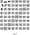
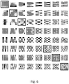
- the two eigenvectors corresponding to an eigenvalue of multiplicity 2 are highlighted by a surrounding rectangle: clearly the eigenvectors with coordinates (1,0) and (0,1) have the same "shape" apart from a 90 degrees (n/2 radians) rotation.
- the present invention discloses an apparatus and method for encoding and decoding images or video streams starting from a new transform whose definition lies on the previous theoretical considerations.
- the invention proposes to use in the image or video coding process a new kind of DCT transform obtained by rotating at least one basis vector of the conventional 2D DCT matrix by at least one rotation angle ( ⁇ ) determined according to certain criteria.
- the inverse domain transform is performed by inverse transforming the image coefficients by using the same, new kind of DCT transform obtained from the conventional 2D DCT in the same way, i.e. effecting the same rotating operation performed at the encoding side.
- the system may use the one that better represents the properties of the specific image or image block to be compressed, i.e. the system will select the basis function that better describes the current samples with, for examples, discontinuities that would have a not performing representation in terms of artifacts and coding efficiency with the conventional 2D-DCT.
- a possible embodiment of the SDCT calculation is shown in Fig. 9 ; first the SDCT transform unit 1101 acquires the original image f or an image block of raw data (step 200); then, at step 201 said unit 1101 selects the optimal angle ⁇ for the current image block.
- One possible method for choosing said rotation angle is provided, in an exemplary way, here below and visually described in Fig. 10 .
- R be, for example, a finite number of angles between 0 and n/2 radians to be tested and V the original 2D-DCT basis matrix.
- J represents an objective function that measures or estimates the coding efficiency associated with the current block; in this case, let J be metric representing (a measure of) the sparsity of the transformed coefficients and J opt the optimal value of said objective function.
- the proposed exhaustive method consist in iteratively trying all the R angles of the set; said method comprises the following steps:
- the optimal angle ⁇ can be applied to the vectors of the original DCT matrix V at step 202 by generating transform information V'.
- the new transform matrix Steerable Discrete Cosine Transform i.e. V' in the above description, can be created as follows. For each eigenbasis with multiplicity greater than 1, the corresponding eigenvectors (or basis vectors) are rotated in pairs. The diagonal elements, which have been proved to have multiplicity 1, remain unchanged. So in some embodiments of the invention the basis vectors or eigenvectors defining eigenbasis with single multiplicity are not rotated, or, equivalently, are rotated by an angle large 0°. Consequently if all other basis vectors of the original DCT matrix are rotated by the same angle, there are multiple sets of basis vectors defining different eigenspaces rotated by the same angle.
- SDCT Steerable Discrete Cosine Transform
- the SDCT transform consists in selecting at least one eigenspace defined by its basis vectors with dimension greater than one and rotating such basis vectors. In such a way, a particular SDCT transform is obtained.
- the invention proposes to use the SDCT for transforming a bidimensional signal for its compression by adapting the transform to the semantics of the signal.
- each eigenspace can be rotated by a different rotation angle, i.e. for each pair of DCT basis the system can select the rotation angle that better represents the current samples block.
- the sets of basis vectors defining different eigenspaces are rotated by different angles.
- each component of the SDCT is oriented according to the angle that maximize the coding efficiency for that particular block.
- the result is an improving of the coding performance when compared to the conventional (2D) DCT and a reconstructed image or video with less visible artifacts at the decoder side.
- at least two sets of basis vectors defining different eigenspaces are rotated by different angles.
- the SDCT is modified such that each DCT original pair is rotated by a different rotation angle according to the coding performance of the image or block image to be represented.
- Another embodiment of the present invention represents a special case of the previous embodiment in which each eigenspace presents the same rotation angle, i.e. each pair of the original DCT basis vector is oriented according to the same rotation angle, if the basis vectors are rotated in pairs. More generally, two or more sets of basis vectors defining two or more eigenspaces are rotated by the same angle.
- the common rotation angle used for obtaining the rotated DCT transform is the only information needed by the decoder in order to recover/decompress the original samples of the image block of a still image or of the video stream, as highlighted in Fig. 8 .
- a coding mode is signaled.
- the coding modes may represent intra or inter prediction modes, partitions for motion-compensated prediction or transform coding.
- the rotation information can be implied in a specific coding mode, known at the encoder and decoded side.
- the rotation angle or angles can also be quantized and possibly entropy coded by the encoding apparatus 11 before being outputted according to known techniques; they can also be multiplexed with the hybrid-encoded image data f ⁇ in any suitable way.
- the decoding apparatus 1110 according to the invention will perform the inverse operation carried out by the encoder in the opposite order: first, the angle value or values are de-multiplexed from the input digital stream, then entropy decoded and finally dequantized before being used for computing the ISDCT on the image coefficients.
- the SDCT transform unit 1101 computes the SDCT transformed coefficients f ⁇ applying the new transform matrix SDCT obtained at step 202 to the image samples f, i.e. SDCT transform unit 1101 multiplies the transform matrix V' for the image vector f, preferably by using Fast Fourier Transform algorithm.
- the SDCT transformed coefficients are then passed to units 1102 and 1103 to be quantized and entropy coded as described before for Fig. 1 for units 102 and 103.
- the entropy coder unit 103 can rearrange the image components from low frequency components to high frequency components (e.g. in a "zigzag" order) and retain the most important ones. Clearly, increasing the number of retained coefficient will lead to a better reconstruction of the original image components.
- the encoding apparatus 11 executes a method for encoding digital images or video streams, wherein said method comprises the following phases:
- Fig. 8 also describes in an exemplary way an image decoder 1110 according to the invention.
- the decoder device 1110 comprises the following parts:
- the processing means 1200 can also be described in structural way, i.e. they can comprise an Inverse SDCT (ISDCT) transform unit 1111, a dequantizer 1112 and an entropy decoder 1113.
- ISDCT Inverse SDCT
- the physical realization of (virtual) elements 1111-1113 can be made either by using a single physical processor executing a set of instruction that implements the functions of at least one of said elements 1111-1113 or by using distinct dedicated hardware components implementing the functions of at least one of said elements 1111-1113 or a combination of both the just mentioned solutions.
- the rotation angles or indicators thereof are transmitted by the encoding apparatus 11 to the decoding apparatus 1110.
- the entropy decoder unit 1113 takes as input the quantized entropy coded coefficients and the angle ⁇ or the angles ⁇ i of the current image block, depending on the selected embodiment of the invention at the encoding side. Namely, at the decoder side, the system can receive one angle value ⁇ , meaning that each pair of corresponding basis vector needs to be rotated by the same angle ⁇ , or more angle values ⁇ i , being i a number that varies as function of the number of pair basis the encoding apparatus decided to rotate in that image block.
- the rotation angles (or the rotation angle) - or indicators thereof - are not transmitted and the rotation information is implied in the associated coding mode, as previously described.
- the encoder apparatus signalizes in the metadata of the bitstream that this coding method is used along with any required information, either explicit or implicit, about the relation between the prediction modes and the rotation angles.
- the decoding apparatus acquires this signalling from the received bitstream and inverts the transform performed at the encoding side on a certain image portion basing on a rotated DCT transform matrix obtained through the same rotation angle(s).
- ⁇ be only one angle and f ⁇ be one image block coefficients.
- the entropy decoder 1113 and the subsequent dequantizer 1112 recover the f ⁇ coefficients (in case of ideal channel transmission) and the angle ⁇ from their encoded and quantized form.
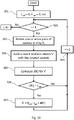
- the Inverse SDCT transform unit 1111 reconstructs the image block f in the space domain based on the procedure described in Fig. 11 .
- Unit 1111 is here represented by the inverse transformation of the Steerable Cosine Transform described above, the Inverse Steerable Cosine Transform or ISDCT or SDCT -1 .
- the ISDCT unit 1111 determines at step 400 the angle ⁇ and acquires from the dequantizer 1112 the (decoded and dequantized) coefficients f ⁇ of the image block (step 401).
- the rotation angle ⁇ of a block is transmitted by the encoding apparatus 11 along with the coefficients f ⁇ .
- the decoding apparatus acquires from the dequantizer also such angle as received by the input interface 1114, decoded by the entropy decoder 1113, and dequantized by dequantizer 1112.
- f is the original block image, however, in a common coding/decoding unit f could be an approximate reconstruction of the original sample due to some lossy coding steps or transmission/reception errors.
- each image block (entropy decoded and dequantized) is processed according to the method steps described in Fig. 11 . If an entire image (either a still image or one being part of a video stream) has to be processed, the above hybrid decoding procedure is repeated for each image block in which the image has been partitioned.
- the aim of using a transform matrix whose vector basis has a different orientation from the horizontal/vertical one is a more compact signal representation obtaining by unbalancing the domain transformed coefficients. For each pair of rotated eigenvectors, the total energy of the corresponding transformed coefficients remains unchanged, but it is possible to sparsify the signal representation in each eigenspace. In the optimal case, the rotation compacts all the energy of the pair in one of the two coefficients.
- the decoding apparatus 1110 executes a method for decoding digital images or video streams, wherein said method comprises the following phases:
- the M term non-linear approximation has been carried out just in order to evaluate the performance of the proposed SDCT transform in a simple way with respect to the conventional 2D-DCT in a less computationally intensive way.
- PSNR Peak Signal to Noise Ratio
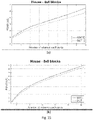
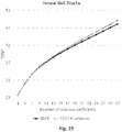
- Fig. 14 shows the results of performance tests of the SDCT as a function of the number of available coefficients for 8x8 blocks.
- Fig. 14 shows the SDCT performance for 4, 16 and 128 angles as a function of the transmitted coefficients (i.e. M in the above formula) against the conventional 2D-DCT.
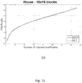
- Fig. 15 illustrates a comparison between DCT and SDCT for a 4x4 block size division ( Fig. 15-a ), 8x8 block size division ( Fig. 15-b ), 16x16 block size division ( Fig. 15-c ).
- the effectiveness of the SDCT increases for smaller image blocks, because it is very likely that in smaller areas a single predominant direction is present in their discontinuities.
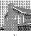
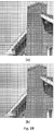
- SDCT ( Fig. 18-b ) provides much better visual quality against DCT ( Fig. 18-a ), minimizing artifacts along the edges thanks to the alignment of the transform to the edge direction given by the new rotated coefficients.
- Figures 21 (a) and (b) show the DCT transformed coefficients and Figures Fig. 22 (a) and (b) the SDCT transformed coefficients.
- the SDCT concentrates the energy in a few coefficients in a very efficient way (i.e. in the ideal case of our toy image, half of the transformed matrix consists of non-zero coefficients).
- the corresponding reconstructed image at the decoder side in Fig. 23-a perfectly follows the diagonal discontinuity crossing the toy image in Fig. 20 .
- the conventional 2D-DCT ( Fig. 21 (a) and (b) ) generated the reconstructed image in Fig. 23-b ; clearly it presents visible noise in the flat areas of the image.
- the preferred embodiment of the present invention relates to grayscale images, however another embodiment involves coding and decoding means for color images in which the chroma components have been processed.
- Fig. 15 shows in an exemplary way some experiments with blocks of 16x16, 8x8, 4x4 pixels.
- the dimension of the SDCT and ISDCT blocks is the same for the whole image.
- each eigenbasis of the original 2D-DCT can be rotated by a different rotation angle, i.e. for each pair of DCT basis the system can select the rotation angle that better represents the current sample. In this way, the SDCT is oriented according to the angle or angles that maximize the coding efficiency for that particular block.
- one or more angles ⁇ are transmitted with the identification of the eigenspace to be rotated;
- the identification metric can be an index in a look-up table containing all possible eigenspaces or the identification metric could be implicit (e.g. the decoder can derive the eigenspace corresponding to ⁇ from the receiving order of the angles).
- the metric of choosing the optimal angle ⁇ is not an exhaustive search but any other search method, i.e. a hierarchical search performed by consecutive enhancement of the optimal angle ⁇ .
- the objective function J could follow a different approach to measure the coding efficiency, for example, a psycho-visual optimization metric can be applied, such as the SSIM (Structural SIMilarity) optimization.
- SSIM Structuretural SIMilarity
- the objective function J could be a psycho-visual optimization metric depending on the Region of Interest (ROI) of the current image, i.e. if the current block pertains to the Region of Interest of the current image, the encoding apparatus could apply psycho-visual optimization only on this part and use any other method on the other parts of the image (or intra frame).
- ROI Region of Interest
- the SDCT is an integer transform; it is known that the implementation of a DCT-like transform with low error needs a long word length arithmetic with a floating-point implementation; this implies a complex hardware implementation.
- Recent encoders and decoders solved this problem by specifying the DCT with integer arithmetic. Integer transform avoids encoder-decoder mismatch and drift caused by slightly different floating-point representations.
- the encoding and decoding apparatuses may perform the choice of the optimal angle in a different way.
- the encoding apparatus in Fig. 8 may comprise memory means (e.g. a Read Only Memory and/or a Random Access Memory and/or Solid State Memory and/or an Hard Disk or the like) containing at least a set of pre-built Steerable Discrete Cosine Transforms; each SDCT having basis rotated by a pre-determined number of angles.
- the choice of the optimal angle can be replaced with the choice of the optimal SDCT among the available ones.
- the information about the chosen SDCT transform e.g.
- the indicator of the selected matrix or the associated coding mode included in the bitstream syntax is conveyed to the decoder apparatus which acquires it and operates the same choice on a corresponding Inverse SDCT selected from a corresponding set of pre-built ISDCTs.
- Such indicator may be associated to a specific coding mode that implies the use of a specific SDCT.
- the above-mentioned set of Steerable Discrete Cosine Transforms can be constructed in a plurality of modes.
- the encoder and decoder could have in memory 16 SDCTs in which each pair of eigenbasis has been rotated by the same angle ⁇ .
- each SDCT in the transform group may have each pair of vectors rotated according to a different rotation angle.
- the angle ⁇ of the current block can be predicted from the angle ⁇ of one or more previously coded blocks of the current image or of a previously coded one. In this case, it is possible to transmit only a "skip" flag (if they are identical) or the predicted difference to the decoder. At the decoder side, when receiving the "skip" flag or the prediction difference, the angle ⁇ will be derived accordingly.
- the transforms DCT and SDCT can be applied in a hybrid manner in order to maximize the coding performances according to the specific semantic of each block or image block.
- the system may use the simple 2D-DCT or any other transform; on the contrary, when the decoder receives the angle ⁇ or a coding mode that implies the angle ⁇ , the decoding apparatus knows that a Steerable Cosine Transform has been applied and reconstructs the transformed coefficients accordingly.
- the SDCT and/or the associated angle/angles can be specified in syntax information of the coded bit stream, for example the PPS (Picture Parameter Set) or the slice header or any other syntax representation known at the encoder and decoder side.
- a sub-band coding could be applied prior to applying the SDCT.
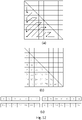
- Sub-band coding decomposes the source output into components on the basis of the frequency. Being the transformation matrix symmetric with respect to the diagonal, it is possible to consider only a subpart of the coefficients, ordered in an arbitrary way, an example of the considered coefficient and an example of a proposed ordering are shown in Fig. 12-a and 12-b .
- SDCT considered coefficients could be subdivided in a variable number of sub-bands
- Fig. 12-c shows an exemplary division in four sub-bands of equal size. Each sub-band is then assigned a different rotation angle ⁇ that better represents the considered samples block.
- FIG. 16 A typical block scheme for video compression exploiting the use of the new SDCT is exemplary described in Fig. 16 .
- the main parts of the video encoding system in Fig. 16 essential to understand the use of the Steerable Cosine Transform in this framework, will be described.
- the encoding system For each image block, the encoding system performs either an intra-frame prediction or motion estimation and compensation to predict the current image samples.
- the intra frame prediction unit (Transform, Scale and Quantize unit 500 in Figure 16 ), additionally with respect to grayscale image coding, performs some processing for the chroma components (e.g. scaling filtering).
- the transform operation performed by unit 500 is a plain 2D-DCT transform.
- the inverse transform operation performed by the Scaling and Inverse transform unit 510 by which a plain Inverse 2D-DCT transform is carried out in order to reconstruct the image samples, compute the rate distortion cost and decide how to perform the hybrid encoding process.
- the unit 500 contains an image-like coding on the intra frames as depicted in Fig. 8 , apart from the entropy coding stage 1103, which is absent; sometimes, depending on the image semantics, the prediction unit can predict the current block from the spatially neighboring blocks.
- the inter-frame prediction unit exploits the motion estimation unit to find the most similar block in a set of previously encoded frames and, through the so-called "motion-compensation", exploit the selected block to predict the current one.
- a difference between the predicted pixel values and the original ones is computed for predictive intra coding and inter-frame coding.
- This difference is often referred to as "residual image” or “residual error” or “residual value”.
- this residual image is then transformed according to the coding method described in Fig. 9 , generating SDCT transformed coefficients (as previously described). These coefficients are quantized and entropy coded before being sent to the channel or memorization unit.
- the SDCT is applied to the residual image blocks.
- the angle ⁇ is the selected direction of the intra frame coding mode; in this case it may not be necessary the transmission of the angle information or the associated coding modes, since the decoding apparatus already receives the intra mode prediction information (e.g. the index) and can easily derive the prediction direction information.
- the intra mode prediction information e.g. the index
- Fig. 17 shows an exemplary video decoding apparatus exploiting the use of Steerable Discrete Cosine Transform.
- the hybrid-encoded samples of a video stream are entropy decoded and de-quantized by, respectively, the entropy decoder 602 and the inverse quantizer 604, recovering the SDCT transformed coefficients.
- SDCT transformed coefficients feed the Intra Frame Decoder 606 which contains the Inverse SDCT (or ISDCT) transform unit operating according to the decoding steps presented in Fig. 11 .
- the output of this decoding phase could be either a residual block or an intra block.
- the decoded samples pertain to a residual block
- the current block has been predicted from a neighbor block inside the same frame (intra-frame prediction) or from a block contained in a previously decoded frame in the reference buffer (inter-frame prediction).
- intra-frame prediction i.e. intra frame prediction
- these residual values are summed to the reference block values inside the current picture
- the Motion-compensated Predictor 608 recovers the motion information (e.g. motion vectors and index of a reference block in one or more previously decoded images/frame) and the residual values are summed to the corresponding block values of one or more previously decoded frames.
- the image can be sent to the display device.
- the image or image block is first analysed with regard to the presence and orientation of discontinuities like borders and/or color changes; depending on the result of the such analysis a decision about the use of a plain 2D-DCT or an SDCT transform is taken; possibly also the optimal angle is selected basing on the orientation of the discontinuities.
- the analysis can be done before starting the hybrid video coding by individuating for the whole image the kind of domain transform to be applied on each block and possibly also the block sizes of the transforms, if an adaptive block size is carried out.
- the analysis is done during the hybrid encoding block by block, and/or image by image in case of video data.
- the dimensions of the SDCT transform can be determined basing on the analysis of the image semantics: for example if two discontinuities having different orientations would be comprised in the same SDCT transform block, i.e. of 16x16, the dimension of the block transform can be reduced to 8x8 or 4x4 until only one of the two discontinuities are present or at least prevailing in distinct transform blocks.
- Hybrid video coding is the context in which the invention has been described; anyway it applies to the compression and decompression of any bidimensional signal in which a domain transform is useful for solving the technical problem faced by the invention, i.e. to increase the coding efficiency by adapting the coefficients obtained by the domain transform to the orientations of the discontinuities present in the bidimensional signal by employing a directional transform.
- image and image block used in the present description as input bi-dimensional signal must be interpreted in their broadest meaning. They can encompass pixel values directly derived or extracted from a natural image, an artificial image, the prediction error of an image, a subsampled version of an image at higher resolution, any portion of said kind of images, or the like.
Landscapes
- Engineering & Computer Science (AREA)
- Multimedia (AREA)
- Signal Processing (AREA)
- General Physics & Mathematics (AREA)
- Physics & Mathematics (AREA)
- Discrete Mathematics (AREA)
- Theoretical Computer Science (AREA)
- Computer Vision & Pattern Recognition (AREA)
- Data Mining & Analysis (AREA)
- Computing Systems (AREA)
- Life Sciences & Earth Sciences (AREA)
- Bioinformatics & Computational Biology (AREA)
- Evolutionary Biology (AREA)
- Evolutionary Computation (AREA)
- General Engineering & Computer Science (AREA)
- Bioinformatics & Cheminformatics (AREA)
- Artificial Intelligence (AREA)
- Compression Or Coding Systems Of Tv Signals (AREA)
Claims (17)
- - Appareil (11) pour coder des images numériques, comprenant- des moyens d'entrée (1104) configurés pour acquérir au moins une partie d'au moins une image (f) provenant d'une source (S),- des moyens de sortie (1105) configurés pour délivrer au moins une partie d'une image codée à une destination (1110),- des moyens de traitement (1100) configurés poura) lire l'au moins une partie de l'image (f),b) déterminer un Laplacien d'un graphe à grille carrée associé à une matrice (V) de transformée en cosinus discrète (DCT) apte à transformer l'au moins une partie de l'image (f) d'un domaine spatial à un domaine fréquentiel,c) déterminer les valeurs propres du Laplacien dont la multiplicité est supérieure à un,d) sélectionner pour au moins l'une des valeurs propres déterminées à l'étape c) un ensemble de vecteurs de base de la matrice DCT qui sont des vecteurs propres du Laplacien correspondant à l'au moins une valeur propre,e) effectuer une rotation de l'ensemble de vecteurs de base d'un angle de rotation (θ),f) déterminer une matrice de transformée ayant subi une rotation (V') qui a comme vecteur de base l'ensemble de vecteurs de base ayant subi une rotation,g) calculer des coefficients transformés (f^) en transformant des valeurs de pixel contenues dans l'au moins une partie de l'image (f) du domaine spatial au domaine fréquentiel au moyen de la matrice de transformée ayant subi une rotation (V'), eth) délivrer, par l'intermédiaire des moyens de sortie (1105), les coefficients transformés (f^) à ladite destination (1110),dans lequel les moyens de traitement (1100) sont configurés pour- déterminer l'angle de rotation (θ) en sélectionnant un angle de rotation qui rend minimale ou rend maximale une fonction économique estimant une efficacité de codage associée à l'au moins une partie de l'image (f), ou- effectuer un codage intra-trame en générant des informations de prédiction intra-trame, et déterminer l'angle de rotation (θ) sur la base des informations de prédiction intra-trame.
- - Appareil de codage (11) selon la revendication 1, dans lequel au moins deux ensembles de vecteurs de base correspondant à des valeurs propres différentes subissent une rotation du même angle de rotation (θ).
- - Appareil de codage (11) selon la revendication 1, dans lequel au moins deux ensembles de vecteurs de base correspondant à des valeurs propres différentes subissent une rotation selon des angles différents.
- - Appareil de codage (11) selon l'une quelconque des revendications 1 à 3, dans lequel la fonction économique détermine une métrique d'optimisation de débit-distorsion sur la base d'une image reconstruite (f') calculée sur la base des coefficients transformés (f^).
- - Appareil de codage (11) selon l'une quelconque des revendications 1 à 4, dans lequel la fonction économique détermine une métrique d'optimisation psycho-visuelle sur la base d'une image reconstruite (f') calculée sur la base des coefficients transformés (f^).
- - Appareil de codage (11) selon l'une quelconque des revendications 1 à 5, comprenant des moyens de mémoire contenant au moins un ensemble de matrices de transformée ayant subi une rotation (V'), dans lequel chaque matrice de transformée ayant subi une rotation (V') est associée à un angle de rotation respectif utilisé pour calculer la matrice de transformée ayant subi une rotation (V') à partir de la matrice de transformée en cosinus discrète (V) respective, dans lequel les moyens de traitement (1100) sont également configurés pour sélectionner la matrice de transformée ayant subi une rotation (V') contenue dans les moyens de mémoire sur la base de l'angle de rotation (θ) déterminé.
- - Appareil de codage (11) selon l'une quelconque des revendications 1 à 6, dans lequel les moyens de traitement (1100) sont configurés pour déterminer l'angle de rotation (θ) également sur la base d'une partie précédemment codée de l'au moins une partie de l'image (f) ou d'une seconde image.
- - Appareil de codage (11) selon l'une quelconque des revendications 1 à 7, dans lequel les moyens de traitement (1100) sont également configurés pour déterminer un nombre de discontinuités présentes dans l'au moins une partie de l'image (f), et pour réduire une taille de l'au moins une partie de l'image (f) si le nombre de discontinuités est supérieur à un.
- - Appareil de codage (11) selon l'une quelconque des revendications 1 à 8, dans lequel les moyens de traitement (1100) sont configurés pour coder au moins une trame en calculant au moins une image résiduelle, et dans lequel l'au moins une partie de l'image (f) est une partie de l'au moins une image résiduelle.
- - Appareil (1110) pour décoder des images numériques, comprenant- des moyens d'entrée (1114) configurés pour acquérir au moins une partie codée d'au moins une image (f) à partir d'un canal de communication ou d'un support de stockage (C),- des moyens de sortie (1115) configurés pour délivrer une image reconstruite (f'),- des moyens de traitement (1200) configurés poura) recevoir, par l'intermédiaire des moyens d'entrée (1114), des coefficients transformés (f^) de l'au moins une partie codée de l'image (f),b) déterminer un Laplacien d'un graphe à grille carrée associé à une matrice de transformée en cosinus discrète (DCT) apte à effectuer une transformée inverse de l'au moins une partie codée de l'image (f) d'un domaine fréquentiel à un domaine spatial,c) déterminer les valeurs propres du Laplacien dont la multiplicité est supérieure à un,d) sélectionner pour au moins l'une des valeurs propres déterminées à l'étape c) un ensemble de vecteurs de base de la matrice DCT qui sont les vecteurs propres du Laplacien correspondant à l'au moins une des valeurs propres,e) effectuer une rotation de l'ensemble sélectionné de vecteurs de base d'un angle de rotation (θ),f) déterminer une matrice de transformée ayant subi une rotation (V') qui a comme vecteurs de base l'ensemble sélectionné de vecteurs de base ayant subi une rotation,g) calculer l'image reconstruite (f') par transformée inverse des coefficients transformés (f^) du domaine fréquentiel au domaine spatial au moyen de la matrice de transformée ayant subi une rotation (V'),h) délivrer, par l'intermédiaire desdits moyens de sortie (1115), l'image reconstruite (f'),dans lequel les moyens de traitement (1100) sont également configurés pour- déterminer l'angle de rotation sur la base d'un indicateur lu par lesdits moyens d'entrée à partir de ladite au moins une partie codée d'au moins ladite image, ou- déterminer l'angle de rotation (θ) en sélectionnant un angle de rotation qui rend minimale ou rend maximale une fonction économique estimant une efficacité de codage associée à l'au moins une partie de l'image (f), ou- effectuer un codage intra-trame en générant des informations de prédiction intra-trame, et déterminer l'angle de rotation (θ) sur la base des informations de prédiction intra-trame, ou- déterminer l'angle de rotation (θ) également sur la base d'une partie précédemment décodée de l'image (f) ou d'une seconde image.
- - Appareil de décodage (1110) selon la revendication 10, dans lequel au moins deux ensembles de vecteurs de base correspondant à des valeurs propres différentes subissent une rotation du même angle de rotation (θ).
- - Appareil de décodage (1110) selon la revendication 10, dans lequel au moins deux ensembles de vecteurs de base correspondant à des valeurs propres différentes subissent une rotation selon des angles différents.
- - Appareil de décodage (1110) selon l'une quelconque des revendications 10 à 12, dans lequel les moyens de traitement (1200) sont configurés pour effectuer une transformée inverse des coefficients transformés (f^) par transposition de la matrice de transformée ayant subi une rotation (V') .
- - Appareil de décodage (1110) selon l'une quelconque des revendications 10 à 13, comprenant en outre des moyens de mémoire contenant au moins un ensemble de matrices de transformée ayant subi une rotation (V'), dans lequel chaque matrice de transformée ayant subi une rotation (V') est associée à un angle de rotation respectif utilisé pour calculer la matrice de transformée ayant subi une rotation (V') à partir de la matrice de transformée en cosinus discrète (V) respective, dans lequel les moyens de traitement (1200) sont également configurés pour sélectionner la matrice de transformée ayant subi une rotation (V') contenue dans les moyens de mémoire sur la base de l'angle de rotation (θ) déterminé.
- - Appareil de décodage (1110) selon l'une quelconque des revendications 10 à 14, dans lequel les moyens de traitement (1200) sont configurés pour décoder au moins une partie de trame sur la base d'au moins un bloc d'image résiduelle reçu par l'intermédiaire des moyens d'entrée (1114).
- - Procédé de codage d'images numériques ou de flux vidéo, comprenant- une phase de réception, dans laquelle au moins une partie d'une image (f) est reçue par l'intermédiaire de moyens d'entrée (1104),- une phase de détermination comprenant :- déterminer un Laplacien d'un graphe à grille carrée associé à une matrice de transformée en cosinus discrète (DCT) apte à transformer l'au moins une partie de l'image (f) d'un domaine spatial à un domaine fréquentiel,- déterminer les valeurs propres du Laplacien dont la multiplicité est supérieure à un,- une phase de sélection comprenant la sélection, pour au moins l'une des valeurs propres, d'un ensemble de vecteurs de base de la matrice DCT qui sont les vecteurs propres du Laplacien correspondant à ladite au moins une des valeurs propres,- une phase de rotation, dans laquelle au moins un angle de rotation (θ) est déterminé, par l'intermédiaire de moyens de traitement (1100), pour effectuer une rotation de l'ensemble sélectionné de vecteurs de base, et dans laquelle une matrice de transformée ayant subi une rotation (V') est déterminée en tant que résultat de la rotation de l'ensemble sélectionné de vecteurs de base de l'au moins un angle de rotation (θ), les moyens de traitement (1100) déterminant l'angle de rotation (θ) en sélectionnant un angle de rotation qui rend minimale ou rend maximale une fonction économique estimant une efficacité de codage associée à l'au moins une partie de l'image (f), ou effectuant un codage intra-trame en générant des informations de prédiction intra-trame et en déterminant l'angle de rotation (θ) sur la base des informations de prédiction intra-trame,- une phase de transformée, dans laquelle des coefficients transformés (f^) sont calculés sur la base de pixels contenus dans l'au moins une partie codée de l'image (f) et de la matrice de transformée ayant subi une rotation (V') en transformant des valeurs de pixel contenues dans l'au moins une partie codée de l'image (f) du domaine spatial au domaine fréquentiel au moyen de la matrice de transformée ayant subi une rotation (V'), et- une phase de sortie, dans laquelle les coefficients transformés (f^) sont transmis à une destination (1110) par l'intermédiaire de moyens de sortie (1105).
- - Procédé de décodage d'images numériques ou de flux vidéo, comprenant- une phase de réception, dans laquelle des coefficients transformés (f^) d'une partie codée d'une image (f) sont reçus par l'intermédiaire de moyens d'entrée (1114),- une phase de détermination comprenant :- déterminer un Laplacien d'un graphe à grille carrée associé à une matrice de transformée en cosinus discrète (DCT) apte à effectuer une transformée inverse de la partie codée de l'image (f) d'un domaine fréquentiel à un domaine spatial,- déterminer les valeurs propres du Laplacien dont la multiplicité est supérieure à un,- une phase de sélection comprenant la sélection, pour au moins l'une des valeurs propres déterminées dans la phase de détermination, d'un ensemble de vecteurs de base de la matrice DCT, qui sont les vecteurs propres du Laplacien correspondant à l'au moins une valeur propre,- une phase de rotation, dans laquelle une matrice de transformée ayant subi une rotation (V') est déterminée par l'intermédiaire de moyens de traitement (1200), dans laquelle la matrice de transformée ayant subi une rotation (V') est déterminée en tant que résultat de la rotation de l'ensemble sélectionné de vecteurs de base de l'au moins un angle de rotation (θ), les moyens de traitement (1100) déterminant l'angle de rotation (θ) sur la base d'un indicateur lu par lesdits moyens d'entrée à partir de ladite partie codée de ladite image, ou en sélectionnant un angle de rotation qui rend minimale ou rend maximale une fonction économique estimant une efficacité de codage associée à l'au moins une partie de l'image (f), ou effectuant un codage intra-trame en générant des informations de prédiction intra-trame et en déterminant l'angle de rotation (θ) sur la base des informations de prédiction intra-trame, ou déterminant l'angle de rotation (θ) également sur la base d'une partie précédemment décodée de l'image (f) ou d'une seconde image,- une phase de transformée inverse, dans laquelle une image reconstruite (f') est calculée sur la base des coefficients transformés (f^) et de la matrice de transformée ayant subi une rotation (V') en effectuant une transformée inverse des coefficients transformés (f^) du domaine fréquentiel au domaine spatial au moyen de la matrice de transformée ayant subi une rotation (V'), et- une phase de sortie, dans laquelle l'image reconstruite (f') est délivrée par l'intermédiaire de moyens de sortie (1115).
Applications Claiming Priority (2)
| Application Number | Priority Date | Filing Date | Title |
|---|---|---|---|
| ITUB2015A005295A ITUB20155295A1 (it) | 2015-10-16 | 2015-10-16 | Apparatuses and methods for encoding and decoding images |
| PCT/IB2016/056138 WO2017064645A1 (fr) | 2015-10-16 | 2016-10-13 | Appareils et procédés permettant de coder et de décoder des images |
Publications (2)
| Publication Number | Publication Date |
|---|---|
| EP3363202A1 EP3363202A1 (fr) | 2018-08-22 |
| EP3363202B1 true EP3363202B1 (fr) | 2022-11-16 |
Family
ID=55085843
Family Applications (1)
| Application Number | Title | Priority Date | Filing Date |
|---|---|---|---|
| EP16791692.3A Active EP3363202B1 (fr) | 2015-10-16 | 2016-10-13 | Appareils et procédés permettant de coder et de décoder des images |
Country Status (5)
| Country | Link |
|---|---|
| US (1) | US11012692B2 (fr) |
| EP (1) | EP3363202B1 (fr) |
| CN (1) | CN108141612B (fr) |
| IT (1) | ITUB20155295A1 (fr) |
| WO (1) | WO2017064645A1 (fr) |
Families Citing this family (16)
| Publication number | Priority date | Publication date | Assignee | Title |
|---|---|---|---|---|
| US11503292B2 (en) * | 2016-02-01 | 2022-11-15 | Lg Electronics Inc. | Method and apparatus for encoding/decoding video signal by using graph-based separable transform |
| US10462203B2 (en) * | 2017-06-13 | 2019-10-29 | Wowza Media Systems, LLC | Hardware encoder |
| WO2019101295A1 (fr) * | 2017-11-21 | 2019-05-31 | Huawei Technologies Co., Ltd. | Appareils et procédé de traitement d'image et de vidéo |
| JP7052075B2 (ja) | 2018-09-02 | 2022-04-11 | エルジー エレクトロニクス インコーポレイティド | 映像信号を処理するための方法および装置 |
| WO2020092137A1 (fr) * | 2018-11-01 | 2020-05-07 | Interdigital Vc Holdings, Inc. | Codage et décodage de vidéo au moyen d'une sélection de transformées multiples |
| JP2020088694A (ja) * | 2018-11-28 | 2020-06-04 | キヤノン株式会社 | 画像処理装置、画像処理方法 |
| CN113767627B (zh) | 2019-04-23 | 2022-11-25 | 北京字节跳动网络技术有限公司 | 基于二次变换的视频处理中的裁剪操作 |
| US11122297B2 (en) * | 2019-05-03 | 2021-09-14 | Google Llc | Using border-aligned block functions for image compression |
| US11432014B2 (en) * | 2019-10-25 | 2022-08-30 | Qualcomm Incorporated | Parametric graph-based separable transforms for video coding |
| CN115606182B (zh) | 2020-03-25 | 2026-02-06 | 抖音视界有限公司 | 使用增强二次变换的编解码视频处理 |
| CN113239934A (zh) * | 2021-03-27 | 2021-08-10 | 重庆邮电大学 | 一种图像处理方法以及相关设备 |
| CN112911289B (zh) * | 2021-05-10 | 2021-08-17 | 杭州雄迈集成电路技术股份有限公司 | 一种dct/idct变换优化方法和系统 |
| KR102571811B1 (ko) | 2021-08-30 | 2023-08-25 | 연세대학교 산학협력단 | 기저 벡터 회전을 이용한 이산코사인변환 방법 및 영상 처리 장치 |
| CN115424180B (zh) * | 2022-09-06 | 2025-12-05 | 北京远鉴信息技术有限公司 | 一种目标识别方法、装置、电子设备及存储介质 |
| US12530790B2 (en) * | 2023-06-21 | 2026-01-20 | Samsung Electronics Co., Ltd. | Hardware-efficient disparity estimation using the DCT of interleaved images |
| CN119229139B (zh) * | 2024-12-05 | 2025-03-21 | 西北工业大学 | 基于离散余弦变换的图像特征描述符的构建方法 |
Family Cites Families (6)
| Publication number | Priority date | Publication date | Assignee | Title |
|---|---|---|---|---|
| JP2003299083A (ja) * | 2002-03-29 | 2003-10-17 | Minolta Co Ltd | 符号化装置、データ変換装置、符号化プログラムおよびデータ変換プログラム |
| US7471850B2 (en) * | 2004-12-17 | 2008-12-30 | Microsoft Corporation | Reversible transform for lossy and lossless 2-D data compression |
| CN101155302B (zh) * | 2006-09-25 | 2012-03-07 | 张燕生 | 一种基于对图像块数据旋转及变换的视频编解码方法 |
| KR101370288B1 (ko) * | 2007-10-24 | 2014-03-05 | 삼성전자주식회사 | 이미지 신호의 압축 방법 및 장치 |
| KR20110065092A (ko) * | 2009-12-09 | 2011-06-15 | 삼성전자주식회사 | 회전 변환을 이용한 영상 부호화, 복호화 방법 및 장치 |
| US9215470B2 (en) * | 2010-07-09 | 2015-12-15 | Qualcomm Incorporated | Signaling selected directional transform for video coding |
-
2015
- 2015-10-16 IT ITUB2015A005295A patent/ITUB20155295A1/it unknown
-
2016
- 2016-10-13 WO PCT/IB2016/056138 patent/WO2017064645A1/fr not_active Ceased
- 2016-10-13 US US15/768,450 patent/US11012692B2/en active Active
- 2016-10-13 EP EP16791692.3A patent/EP3363202B1/fr active Active
- 2016-10-13 CN CN201680060372.0A patent/CN108141612B/zh active Active
Also Published As
| Publication number | Publication date |
|---|---|
| WO2017064645A1 (fr) | 2017-04-20 |
| ITUB20155295A1 (it) | 2017-04-16 |
| EP3363202A1 (fr) | 2018-08-22 |
| CN108141612B (zh) | 2021-03-02 |
| CN108141612A (zh) | 2018-06-08 |
| US11012692B2 (en) | 2021-05-18 |
| US20180338143A1 (en) | 2018-11-22 |
Similar Documents
| Publication | Publication Date | Title |
|---|---|---|
| EP3363202B1 (fr) | Appareils et procédés permettant de coder et de décoder des images | |
| US20250133201A1 (en) | Method and apparatus for encoding/decoding an image signal | |
| US10523951B2 (en) | Systems and methods for processing a digital image | |
| AU2015261728B2 (en) | Method and apparatus for intra prediction within display screen | |
| US8224100B2 (en) | Method and device for intra prediction coding and decoding of image | |
| US9189869B2 (en) | Apparatus and method for encoding/decoding images for intra-prediction | |
| US9386325B2 (en) | Method and apparatus for encoding and decoding image by using large transformation unit | |
| EP2996336B1 (fr) | Dispositif d'interpolation d'images au moyen d'un filtre d'interpolation de lissage | |
| US20170099503A1 (en) | Method and apparatus for encoding/decoding image | |
| US9942568B2 (en) | Hybrid transform scheme for video coding | |
| US20150256841A1 (en) | Method for encoding/decoding high-resolution image and device for performing same | |
| US20140192876A1 (en) | Image encoding/decoding apparatus and method to which filter selection by precise units is applied | |
| EP3590193B1 (fr) | Procédé et appareil de codage et de décodage d'images numériques ou de flux vidéo | |
| US11153564B2 (en) | Systems and methods for processing a block of a digital image | |
| US20110134999A1 (en) | Method and apparatus for encoding video, and method and apparatus for decoding video | |
| US20080219576A1 (en) | Method and apparatus for encoding/decoding image | |
| US20180288438A1 (en) | Method and apparatus for processing video signals using coefficient induced prediction | |
| US10893274B2 (en) | Method for processing video signal on basis of arbitrary partition transform | |
| US11265575B2 (en) | Image and video processing apparatuses and methods |
Legal Events
| Date | Code | Title | Description |
|---|---|---|---|
| STAA | Information on the status of an ep patent application or granted ep patent |
Free format text: STATUS: UNKNOWN |
|
| STAA | Information on the status of an ep patent application or granted ep patent |
Free format text: STATUS: THE INTERNATIONAL PUBLICATION HAS BEEN MADE |
|
| PUAI | Public reference made under article 153(3) epc to a published international application that has entered the european phase |
Free format text: ORIGINAL CODE: 0009012 |
|
| STAA | Information on the status of an ep patent application or granted ep patent |
Free format text: STATUS: REQUEST FOR EXAMINATION WAS MADE |
|
| 17P | Request for examination filed |
Effective date: 20180327 |
|
| AK | Designated contracting states |
Kind code of ref document: A1 Designated state(s): AL AT BE BG CH CY CZ DE DK EE ES FI FR GB GR HR HU IE IS IT LI LT LU LV MC MK MT NL NO PL PT RO RS SE SI SK SM TR |
|
| AX | Request for extension of the european patent |
Extension state: BA ME |
|
| DAV | Request for validation of the european patent (deleted) | ||
| DAX | Request for extension of the european patent (deleted) | ||
| STAA | Information on the status of an ep patent application or granted ep patent |
Free format text: STATUS: EXAMINATION IS IN PROGRESS |
|
| 17Q | First examination report despatched |
Effective date: 20210222 |
|
| REG | Reference to a national code |
Ref country code: DE Ref legal event code: R079 Ref document number: 602016076374 Country of ref document: DE Free format text: PREVIOUS MAIN CLASS: H04N0019625000 Ipc: H04N0001410000 |
|
| RIC1 | Information provided on ipc code assigned before grant |
Ipc: H04N 19/122 20140101ALI20220511BHEP Ipc: H04N 19/176 20140101ALI20220511BHEP Ipc: H04N 19/147 20140101ALI20220511BHEP Ipc: H04N 19/625 20140101ALI20220511BHEP Ipc: H04N 1/41 20060101AFI20220511BHEP |
|
| GRAP | Despatch of communication of intention to grant a patent |
Free format text: ORIGINAL CODE: EPIDOSNIGR1 |
|
| STAA | Information on the status of an ep patent application or granted ep patent |
Free format text: STATUS: GRANT OF PATENT IS INTENDED |
|
| INTG | Intention to grant announced |
Effective date: 20220624 |
|
| GRAS | Grant fee paid |
Free format text: ORIGINAL CODE: EPIDOSNIGR3 |
|
| GRAA | (expected) grant |
Free format text: ORIGINAL CODE: 0009210 |
|
| STAA | Information on the status of an ep patent application or granted ep patent |
Free format text: STATUS: THE PATENT HAS BEEN GRANTED |
|
| AK | Designated contracting states |
Kind code of ref document: B1 Designated state(s): AL AT BE BG CH CY CZ DE DK EE ES FI FR GB GR HR HU IE IS IT LI LT LU LV MC MK MT NL NO PL PT RO RS SE SI SK SM TR |
|
| REG | Reference to a national code |
Ref country code: GB Ref legal event code: FG4D |
|
| REG | Reference to a national code |
Ref country code: CH Ref legal event code: EP |
|
| REG | Reference to a national code |
Ref country code: IE Ref legal event code: FG4D |
|
| REG | Reference to a national code |
Ref country code: DE Ref legal event code: R096 Ref document number: 602016076374 Country of ref document: DE |
|
| REG | Reference to a national code |
Ref country code: AT Ref legal event code: REF Ref document number: 1532479 Country of ref document: AT Kind code of ref document: T Effective date: 20221215 |
|
| REG | Reference to a national code |
Ref country code: LT Ref legal event code: MG9D |
|
| REG | Reference to a national code |
Ref country code: NL Ref legal event code: MP Effective date: 20221116 |
|
| REG | Reference to a national code |
Ref country code: AT Ref legal event code: MK05 Ref document number: 1532479 Country of ref document: AT Kind code of ref document: T Effective date: 20221116 |
|
| PG25 | Lapsed in a contracting state [announced via postgrant information from national office to epo] |
Ref country code: SE Free format text: LAPSE BECAUSE OF FAILURE TO SUBMIT A TRANSLATION OF THE DESCRIPTION OR TO PAY THE FEE WITHIN THE PRESCRIBED TIME-LIMIT Effective date: 20221116 Ref country code: PT Free format text: LAPSE BECAUSE OF FAILURE TO SUBMIT A TRANSLATION OF THE DESCRIPTION OR TO PAY THE FEE WITHIN THE PRESCRIBED TIME-LIMIT Effective date: 20230316 Ref country code: NO Free format text: LAPSE BECAUSE OF FAILURE TO SUBMIT A TRANSLATION OF THE DESCRIPTION OR TO PAY THE FEE WITHIN THE PRESCRIBED TIME-LIMIT Effective date: 20230216 Ref country code: LT Free format text: LAPSE BECAUSE OF FAILURE TO SUBMIT A TRANSLATION OF THE DESCRIPTION OR TO PAY THE FEE WITHIN THE PRESCRIBED TIME-LIMIT Effective date: 20221116 Ref country code: FI Free format text: LAPSE BECAUSE OF FAILURE TO SUBMIT A TRANSLATION OF THE DESCRIPTION OR TO PAY THE FEE WITHIN THE PRESCRIBED TIME-LIMIT Effective date: 20221116 Ref country code: ES Free format text: LAPSE BECAUSE OF FAILURE TO SUBMIT A TRANSLATION OF THE DESCRIPTION OR TO PAY THE FEE WITHIN THE PRESCRIBED TIME-LIMIT Effective date: 20221116 Ref country code: AT Free format text: LAPSE BECAUSE OF FAILURE TO SUBMIT A TRANSLATION OF THE DESCRIPTION OR TO PAY THE FEE WITHIN THE PRESCRIBED TIME-LIMIT Effective date: 20221116 |
|
| PG25 | Lapsed in a contracting state [announced via postgrant information from national office to epo] |
Ref country code: RS Free format text: LAPSE BECAUSE OF FAILURE TO SUBMIT A TRANSLATION OF THE DESCRIPTION OR TO PAY THE FEE WITHIN THE PRESCRIBED TIME-LIMIT Effective date: 20221116 Ref country code: PL Free format text: LAPSE BECAUSE OF FAILURE TO SUBMIT A TRANSLATION OF THE DESCRIPTION OR TO PAY THE FEE WITHIN THE PRESCRIBED TIME-LIMIT Effective date: 20221116 Ref country code: LV Free format text: LAPSE BECAUSE OF FAILURE TO SUBMIT A TRANSLATION OF THE DESCRIPTION OR TO PAY THE FEE WITHIN THE PRESCRIBED TIME-LIMIT Effective date: 20221116 Ref country code: IS Free format text: LAPSE BECAUSE OF FAILURE TO SUBMIT A TRANSLATION OF THE DESCRIPTION OR TO PAY THE FEE WITHIN THE PRESCRIBED TIME-LIMIT Effective date: 20230316 Ref country code: HR Free format text: LAPSE BECAUSE OF FAILURE TO SUBMIT A TRANSLATION OF THE DESCRIPTION OR TO PAY THE FEE WITHIN THE PRESCRIBED TIME-LIMIT Effective date: 20221116 Ref country code: GR Free format text: LAPSE BECAUSE OF FAILURE TO SUBMIT A TRANSLATION OF THE DESCRIPTION OR TO PAY THE FEE WITHIN THE PRESCRIBED TIME-LIMIT Effective date: 20230217 |
|
| P01 | Opt-out of the competence of the unified patent court (upc) registered |
Effective date: 20230516 |
|
| PG25 | Lapsed in a contracting state [announced via postgrant information from national office to epo] |
Ref country code: NL Free format text: LAPSE BECAUSE OF FAILURE TO SUBMIT A TRANSLATION OF THE DESCRIPTION OR TO PAY THE FEE WITHIN THE PRESCRIBED TIME-LIMIT Effective date: 20221116 |
|
| PG25 | Lapsed in a contracting state [announced via postgrant information from national office to epo] |
Ref country code: SM Free format text: LAPSE BECAUSE OF FAILURE TO SUBMIT A TRANSLATION OF THE DESCRIPTION OR TO PAY THE FEE WITHIN THE PRESCRIBED TIME-LIMIT Effective date: 20221116 Ref country code: RO Free format text: LAPSE BECAUSE OF FAILURE TO SUBMIT A TRANSLATION OF THE DESCRIPTION OR TO PAY THE FEE WITHIN THE PRESCRIBED TIME-LIMIT Effective date: 20221116 Ref country code: EE Free format text: LAPSE BECAUSE OF FAILURE TO SUBMIT A TRANSLATION OF THE DESCRIPTION OR TO PAY THE FEE WITHIN THE PRESCRIBED TIME-LIMIT Effective date: 20221116 Ref country code: DK Free format text: LAPSE BECAUSE OF FAILURE TO SUBMIT A TRANSLATION OF THE DESCRIPTION OR TO PAY THE FEE WITHIN THE PRESCRIBED TIME-LIMIT Effective date: 20221116 Ref country code: CZ Free format text: LAPSE BECAUSE OF FAILURE TO SUBMIT A TRANSLATION OF THE DESCRIPTION OR TO PAY THE FEE WITHIN THE PRESCRIBED TIME-LIMIT Effective date: 20221116 |
|
| REG | Reference to a national code |
Ref country code: DE Ref legal event code: R097 Ref document number: 602016076374 Country of ref document: DE |
|
| PG25 | Lapsed in a contracting state [announced via postgrant information from national office to epo] |
Ref country code: SK Free format text: LAPSE BECAUSE OF FAILURE TO SUBMIT A TRANSLATION OF THE DESCRIPTION OR TO PAY THE FEE WITHIN THE PRESCRIBED TIME-LIMIT Effective date: 20221116 Ref country code: AL Free format text: LAPSE BECAUSE OF FAILURE TO SUBMIT A TRANSLATION OF THE DESCRIPTION OR TO PAY THE FEE WITHIN THE PRESCRIBED TIME-LIMIT Effective date: 20221116 |
|
| PLBE | No opposition filed within time limit |
Free format text: ORIGINAL CODE: 0009261 |
|
| STAA | Information on the status of an ep patent application or granted ep patent |
Free format text: STATUS: NO OPPOSITION FILED WITHIN TIME LIMIT |
|
| 26N | No opposition filed |
Effective date: 20230817 |
|
| PG25 | Lapsed in a contracting state [announced via postgrant information from national office to epo] |
Ref country code: SI Free format text: LAPSE BECAUSE OF FAILURE TO SUBMIT A TRANSLATION OF THE DESCRIPTION OR TO PAY THE FEE WITHIN THE PRESCRIBED TIME-LIMIT Effective date: 20221116 |
|
| PG25 | Lapsed in a contracting state [announced via postgrant information from national office to epo] |
Ref country code: MC Free format text: LAPSE BECAUSE OF FAILURE TO SUBMIT A TRANSLATION OF THE DESCRIPTION OR TO PAY THE FEE WITHIN THE PRESCRIBED TIME-LIMIT Effective date: 20221116 |
|
| REG | Reference to a national code |
Ref country code: CH Ref legal event code: PL |
|
| REG | Reference to a national code |
Ref country code: BE Ref legal event code: MM Effective date: 20231031 |
|
| PG25 | Lapsed in a contracting state [announced via postgrant information from national office to epo] |
Ref country code: LU Free format text: LAPSE BECAUSE OF NON-PAYMENT OF DUE FEES Effective date: 20231013 |
|
| PG25 | Lapsed in a contracting state [announced via postgrant information from national office to epo] |
Ref country code: LU Free format text: LAPSE BECAUSE OF NON-PAYMENT OF DUE FEES Effective date: 20231013 |
|
| PG25 | Lapsed in a contracting state [announced via postgrant information from national office to epo] |
Ref country code: CH Free format text: LAPSE BECAUSE OF NON-PAYMENT OF DUE FEES Effective date: 20231031 |
|
| PG25 | Lapsed in a contracting state [announced via postgrant information from national office to epo] |
Ref country code: CH Free format text: LAPSE BECAUSE OF NON-PAYMENT OF DUE FEES Effective date: 20231031 |
|
| PG25 | Lapsed in a contracting state [announced via postgrant information from national office to epo] |
Ref country code: BE Free format text: LAPSE BECAUSE OF NON-PAYMENT OF DUE FEES Effective date: 20231031 |
|
| PG25 | Lapsed in a contracting state [announced via postgrant information from national office to epo] |
Ref country code: IE Free format text: LAPSE BECAUSE OF NON-PAYMENT OF DUE FEES Effective date: 20231013 |
|
| PG25 | Lapsed in a contracting state [announced via postgrant information from national office to epo] |
Ref country code: IE Free format text: LAPSE BECAUSE OF NON-PAYMENT OF DUE FEES Effective date: 20231013 |
|
| PG25 | Lapsed in a contracting state [announced via postgrant information from national office to epo] |
Ref country code: BG Free format text: LAPSE BECAUSE OF FAILURE TO SUBMIT A TRANSLATION OF THE DESCRIPTION OR TO PAY THE FEE WITHIN THE PRESCRIBED TIME-LIMIT Effective date: 20221116 |
|
| PG25 | Lapsed in a contracting state [announced via postgrant information from national office to epo] |
Ref country code: BG Free format text: LAPSE BECAUSE OF FAILURE TO SUBMIT A TRANSLATION OF THE DESCRIPTION OR TO PAY THE FEE WITHIN THE PRESCRIBED TIME-LIMIT Effective date: 20221116 |
|
| PG25 | Lapsed in a contracting state [announced via postgrant information from national office to epo] |
Ref country code: CY Free format text: LAPSE BECAUSE OF FAILURE TO SUBMIT A TRANSLATION OF THE DESCRIPTION OR TO PAY THE FEE WITHIN THE PRESCRIBED TIME-LIMIT; INVALID AB INITIO Effective date: 20161013 |
|
| PG25 | Lapsed in a contracting state [announced via postgrant information from national office to epo] |
Ref country code: HU Free format text: LAPSE BECAUSE OF FAILURE TO SUBMIT A TRANSLATION OF THE DESCRIPTION OR TO PAY THE FEE WITHIN THE PRESCRIBED TIME-LIMIT; INVALID AB INITIO Effective date: 20161013 |
|
| PG25 | Lapsed in a contracting state [announced via postgrant information from national office to epo] |
Ref country code: TR Free format text: LAPSE BECAUSE OF FAILURE TO SUBMIT A TRANSLATION OF THE DESCRIPTION OR TO PAY THE FEE WITHIN THE PRESCRIBED TIME-LIMIT Effective date: 20221116 |
|
| PGFP | Annual fee paid to national office [announced via postgrant information from national office to epo] |
Ref country code: DE Payment date: 20251030 Year of fee payment: 10 |
|
| PGFP | Annual fee paid to national office [announced via postgrant information from national office to epo] |
Ref country code: GB Payment date: 20251024 Year of fee payment: 10 |
|
| PGFP | Annual fee paid to national office [announced via postgrant information from national office to epo] |
Ref country code: IT Payment date: 20251030 Year of fee payment: 10 |
|
| PGFP | Annual fee paid to national office [announced via postgrant information from national office to epo] |
Ref country code: FR Payment date: 20251024 Year of fee payment: 10 |