EP3363280A1 - Système d'entraînement pour une tête de récolte d'une machine de récolte à transmission de puissance hydraulique - Google Patents
Système d'entraînement pour une tête de récolte d'une machine de récolte à transmission de puissance hydraulique Download PDFInfo
- Publication number
- EP3363280A1 EP3363280A1 EP18152946.2A EP18152946A EP3363280A1 EP 3363280 A1 EP3363280 A1 EP 3363280A1 EP 18152946 A EP18152946 A EP 18152946A EP 3363280 A1 EP3363280 A1 EP 3363280A1
- Authority
- EP
- European Patent Office
- Prior art keywords
- header
- hydraulic
- hydraulic motor
- motor
- harvesting
- Prior art date
- Legal status (The legal status is an assumption and is not a legal conclusion. Google has not performed a legal analysis and makes no representation as to the accuracy of the status listed.)
- Granted
Links
Images

Classifications
-
- A—HUMAN NECESSITIES
- A01—AGRICULTURE; FORESTRY; ANIMAL HUSBANDRY; HUNTING; TRAPPING; FISHING
- A01D—HARVESTING; MOWING
- A01D41/00—Combines, i.e. harvesters or mowers combined with threshing devices
- A01D41/12—Details of combines
- A01D41/14—Mowing tables
- A01D41/142—Header drives
-
- A—HUMAN NECESSITIES
- A01—AGRICULTURE; FORESTRY; ANIMAL HUSBANDRY; HUNTING; TRAPPING; FISHING
- A01B—SOIL WORKING IN AGRICULTURE OR FORESTRY; PARTS, DETAILS, OR ACCESSORIES OF AGRICULTURAL MACHINES OR IMPLEMENTS, IN GENERAL
- A01B59/00—Devices specially adapted for connection between animals or tractors and agricultural machines or implements
- A01B59/06—Devices specially adapted for connection between animals or tractors and agricultural machines or implements for machines mounted on tractors
- A01B59/064—Devices specially adapted for connection between animals or tractors and agricultural machines or implements for machines mounted on tractors for connection to the front of the tractor
-
- A—HUMAN NECESSITIES
- A01—AGRICULTURE; FORESTRY; ANIMAL HUSBANDRY; HUNTING; TRAPPING; FISHING
- A01D—HARVESTING; MOWING
- A01D41/00—Combines, i.e. harvesters or mowers combined with threshing devices
- A01D41/12—Details of combines
- A01D41/127—Control or measuring arrangements specially adapted for combines
- A01D41/1274—Control or measuring arrangements specially adapted for combines for drives
-
- A—HUMAN NECESSITIES
- A01—AGRICULTURE; FORESTRY; ANIMAL HUSBANDRY; HUNTING; TRAPPING; FISHING
- A01D—HARVESTING; MOWING
- A01D69/00—Driving mechanisms or parts thereof for harvesters or mowers
- A01D69/03—Driving mechanisms or parts thereof for harvesters or mowers fluid
-
- A—HUMAN NECESSITIES
- A01—AGRICULTURE; FORESTRY; ANIMAL HUSBANDRY; HUNTING; TRAPPING; FISHING
- A01D—HARVESTING; MOWING
- A01D89/00—Pick-ups for loaders, chaff-cutters, balers, field-threshers, or the like, i.e. attachments for picking-up hay or the like field crops
- A01D89/005—Drives
-
- A—HUMAN NECESSITIES
- A01—AGRICULTURE; FORESTRY; ANIMAL HUSBANDRY; HUNTING; TRAPPING; FISHING
- A01F—PROCESSING OF HARVESTED PRODUCE; HAY OR STRAW PRESSES; DEVICES FOR STORING AGRICULTURAL OR HORTICULTURAL PRODUCE
- A01F29/00—Cutting apparatus specially adapted for cutting hay, straw or the like
- A01F29/09—Details
- A01F29/14—Drives
Definitions
- the invention relates to a drive system for a harvesting attachment of a harvesting machine, comprising a drive motor and a drive train connected between the drive motor and one or more driven elements of the header with an adjustable hydraulic pump arranged on board the harvesting machine and a hydraulic motor connected in a closed circuit to the hydraulic pump , and a corresponding harvester with a header.
- Self-propelled harvesters are usually equipped with demountable harvesting attachments, which are removed for road transport from a feeder channel attached to the front of the harvester and, if necessary, exchanged for another harvesting header for harvesting another crop.
- the drive of the header is usually done by the harvester and can provide a purely mechanical drive train between the drive motor of the harvester and the header, or the header is driven by a hydraulic motor, which is acted upon by a powered by the drive motor of the harvester hydraulic pump with pressurized hydraulic fluid becomes.
- the post-published DE 10 2017 200 330 A1 Although describes a header drive in a closed hydraulic circuit with a on board the header hydraulic motor, but does not mention a detachable hydraulic coupling connection between header and harvester.
- a closed hydraulic circuit for driving the header has the advantage that the transmissible drive power can be greater than in an open hydraulic circuit. So far, such closed hydraulic circuits were always provided completely on board the harvester and transferred the drive power of the hydraulic motor by a separable mechanical drive train on the header, or mechanically transferred to the header drive power is transmitted through a arranged exclusively on board the harvesting header, closed hydraulic circuit. Although there was also the transfer of hydraulic power from the harvester to the header, but only in an open hydraulic circuit that can only transmit limited power.
- the object underlying the invention is seen to provide a drive system for a header of a harvester and a corresponding harvester with a header which does not require a mechanical drive connection between the harvester and the header, but nevertheless a transmission of a sufficiently large drive power allows.
- a drive system for a harvesting header of a harvesting machine comprises a drive motor and a drive train connected between the drive motor and one or more driven elements of the header having an adjustable hydraulic pump mounted on the harvester and a hydraulic motor connected in a closed loop to the hydraulic pump at the header attached and is connected by releasable hydraulic coupling connections with the hydraulic pump.
- the line leading from the hydraulic pump to the hydraulic motor may include a first coupling connection and the line returning from the hydraulic motor to the hydraulic pump may include a second coupling connection, the first and second coupling connections being respectively mounted to a common holder on the harvesting attachment side and the harvesting machine side.
- the header can be provided with a readable by the harvester label that can be fed to a control device, which is recognizable in the case of the information associated with one of the label that the header contains a hydraulic motor for driving the header, is operable between the Open hydraulic pump and the hydraulic motor arranged valve.
- a harvesting machine-side hydraulic motor can continue to be present, with which a harvesting attachment not equipped with a hydraulic motor can be driven.
- the control device may be operable to transfer a valve arranged between the hydraulic pump and the hydraulic motor into a position connecting the harvesting machine-side hydraulic motor with the hydraulic pump or commanding the engine-side hydraulic motor designed as an adjusting motor to a neutral position, if the header is not provided with an identification , which indicates that the header is equipped with a hydraulic motor.
- the identification may also contain further operating data of the header, such as maximum drive torque or appropriate speeds, which can be read out and taken into account by the control device.
- the harvest engine side hydraulic motor and the valve can be omitted. Then all harvesting attachments to be used with the harvester would be equipped with a hydraulic motor.
- the harvesting machine side coupling connections can be separated from the hydraulic pump by the valve in its position connecting the harvesting machine side hydraulic motor with the hydraulic pump.
- the header can be a picker with a cross auger and a tine rotor.
- the drive of the cross auger can be done by the hydraulic motor.
- the hydraulic motor can be arranged within the transverse screw conveyor and / or designed as a radial piston motor.
- the drive of the tine rotor can be effected via a hydrostatic transmission which can be driven by the transverse screw conveyor.
- FIG. 1 a harvester 10 is shown in the manner of a self-propelled forage harvester in a schematic side view.
- the harvester 10 is built on a frame 12 supported by front driven wheels 14 and steerable rear wheels 16.
- the operation of the harvesting machine 10 is carried out by a driver's cab 18, from which a header 20 is visible.
- the harvester 20 operatively separable from the harvesting machine 10 is designed as a pick-up in the illustrated embodiment and comprises a transverse screw conveyor 74, a zinc rotor 84 arranged in front of it and support wheels 88 and a downholder 92 above the zinc rotor 84.
- a feed conveyor 22 with Vorpresswalzen which are arranged within a feed housing 24 on the front side of the forage harvester 10, arranged below the driver's cab 18 chopper 26 in the form of a chopper drum, which chops it into small pieces and it Releases conveyor 28.
- the crop leaves the harvesting machine 10 to a transporting vehicle traveling alongside, via a discharge shaft 30 that is rotatable about an approximately vertical axis and can be tilted.
- directional details such as laterally, downwardly and upwardly, refer to the forward direction V of the harvesting machine 10, which in FIG of the FIG. 1 goes to the right.
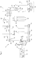
- FIG. 2 shows a plan view of the drive assembly of the harvester 10 and the Harvesting header 20.
- an internal combustion engine serving as a drive motor 32, in particular in the form of a diesel engine, which is connected to longitudinal members and / or cross members of the frame 12.
- the engine 32 extends in the forward direction of the harvester 10 to about the rear end of the frame 12 and includes a crankshaft 34 that extends forward out of the housing of the engine 32.
- the crankshaft 34 drives a horizontally and forwardly extending output shaft 36.
- the output shaft 36 is connected at its front end with an angle gear 38, which is composed of a first bevel gear 40, which is connected via a coupling 42 with the longitudinal shaft 36, and a second bevel gear 44, which meshes with the first bevel gear 40.
- the axis of rotation of the second bevel gear 44 extends horizontally and transversely to the forward direction.
- the second bevel gear 44 is connected to a shaft 46 which drives a pulley 48.
- the pulley 48 is wrapped by a drive belt 50, which also wraps around a pulley 52 for driving the conveyor 28 and a pulley 54 for driving the chopper 26.
- the angle gear 38, the shaft 46, the pulleys 48 and 54 and the drive belt 50 form a drive train connecting the output shaft 36 with the chopper 26.
- the longitudinal shaft 36 carries between the clutch 42 and the housing of the engine 32 in addition a circumferentially toothed gear 56 which meshes with another gear 58, which drives a pump unit 62 via a shaft 60, which is to supply the hydraulic motors for driving the wheels fourteenth , 16, a via a transmission 64 for driving the intake conveyor 22 serving hydraulic motor 78 and other hydraulically driven components of the harvester 10 is used.
- the shaft 46 is in the illustrated embodiment permanently in drive connection with a hydraulic pump 66 with adjustable displacement and flow direction.
- the hydraulic pump 66 is hydraulically fluidically connected in a closed circuit to a hydraulic motor 68, which has a fixed displacement and is used to drive the driven elements of the header 20, which could also be a header for maize harvesting or production of whole plant silage.
- the hydraulic motor 68 (or several hydraulic motors 68) would be used to drive mowing equipment and Serve subsidies for the crop.
- An outlet 82 of the hydraulic pump 66 and an inlet 86 of the hydraulic motor 68 are interconnected by a first pressure line 120.
- An inlet 80 of the hydraulic pump 66 and an outlet 72 of the hydraulic motor 68 are interconnected by a second pressure line 122.
- the hydraulic motor 68 and the hydraulic pump 66 are operated in a closed circuit, which allows the transmission of sufficiently large pressure and sufficient flow rate of the hydraulic fluid and thus a sufficient drive power to drive the movable elements of the header 20.
- the hydraulic motor 68 is located on board the header 20.
- detachable coupling connections in the pressure lines 120, 122 are provided, each having a clutch 104 and 108 by the harvester 10 and a Plug 106 and 110 on the part of the header 20 include.
- the plugs 106, 110 are combined in a holder 100 on the header side.
- the couplings 104, 108 are summarized erntemaschinen mon spirit in a holder 102.
- the holders 100, 102 can be used in particular as a so-called multi-coupler (s. EP 1 346 625 A1 ) and allow both pressure lines 120 and 122 to be disconnected or connected simultaneously.
- a leakage oil line (not shown) can be guided via the holders 100, 102.
- a storage device 90 is provided, which is connected via a line 124 to a control device 70.
- the line 124 includes a plug 112 and a coupling 114, which are also respectively integrated into the holder 100 or 102 and connected or disconnected therewith.
- the hydraulic motor 68 serves to drive the transverse screw conveyor 74.
- the hydraulic motor 68 can be designed as a radial piston motor. Such radial piston motors allow speeds that are suitable for driving the cross auger 74 without the interposition of a transmission gear.
- the output shaft 126 of the hydraulic motor 68 is therefore directly connected via a flange 128 to the inner wall of the hollow interior of the cross auger 74.
- the hydraulic motor 68 is disposed within the hollow interior of the cross auger 74 in the illustrated embodiment, but could be mounted outside the hollow interior.
- transverse screw conveyor 74 it would also be conceivable to drive the transverse screw conveyor 74 by means of an axial piston motor and, if required, to provide a gearbox for speed change (in particular reduction) between the axial piston motor and the transverse screw conveyor 74.
- the axial piston motor and possibly the transmission can be mounted in the hollow interior of the transverse auger 74.
- the drive of the tine rotor 84 via a arranged on board the harvesting attachment 20, hydrostatic transmission with a second hydraulic pump 130 and a second hydraulic motor 132.
- the drive shaft of the second hydraulic pump 130 is coupled to the cross auger 74.
- the output shaft 138 of the second hydraulic motor 132 is coupled to the tine rotor 84.
- the second hydraulic pump 130 and / or the second hydraulic motor 132 could also be located within the hollow interior of the cross auger 74 and the tine rotor 84, respectively.
- the second hydraulic pump 130 is connected to the second hydraulic motor 132 in a closed circuit.
- the delivery volume of the second hydraulic pump 130 can be adjusted by means of an actuator which can be connected to the control device 70 via a further line (not shown) guided via the holders 100 and 102 and separable there.
- the memory unit 90 and / or the actuator 134 can be connected to the control device 70 in particular via a bus system.
- the controller 70 controls an actuator 76 that affects the flow rate and flow direction of the hydraulic pump 66. Finally, the control device 70 is connected to an actuator 94, which opens and closes the clutch 42, and to an operator input device 98, which is arranged in the driver's cab 18, and has an integrated display unit.
- the operator input device 98 allows the operator to select a (road) driving operation in which the clutch 42 is open and neither the chopper 26 nor the feed conveyor 22 is driven, since then the other hydraulic motor 78 is not driven. Also, the hydraulic pump 66 and thus the driven elements (transverse auger 74 and tine rotor 84) of the header 20 are stationary because of the open clutch 42. The wheels 14 and possibly (in four-wheel drive) also 16 are driven by their hydraulic motors and the pump unit 62.
- the operator input device 98 allows the operator to select a first operating mode (harvesting operation) in which the clutch 42 is closed and the chopping device 26 and the conveying device 28 are driven via the drive belt 50.
- the shaft 46 then also drives the hydraulic pump 66, which acts on the hydraulic motor 68 via the first pressure line 120, which in turn drives the transverse conveyor screw 74 of the header 20 and via the hydrostatic transmission with the second hydraulic pump 130 and the second hydraulic motor 132 the zinc rotor 84.
- Of the Feed conveyor 22 is then driven by the pump unit 62 via the further hydraulic motor 78.
- the actuator 76 is controlled by the control device 70 in such a way that a desired collection speed of the header 20 can be input by the operator input device 98 or is automatically predetermined by the controller based on measurements of sensors that detect properties of the crop, such as moisture or compressibility, or defined by data stored in memory device 90.
- the actuator 134 is controlled by the control device 70 such that the zinc rotor 84 is driven at a desired speed.
- the hydraulic fluid from the outlet 82 of the hydraulic pump 66 flows through the pressure line 120 to the inlet 86 of the hydraulic motor 68 and from the outlet 72 through the second pressure line 122 to the inlet 80 of the hydraulic pump 66.
- the terms inlet and outlet, respectively, refer to FIGS Flow direction of the hydraulic fluid in the harvesting operation, which is also indicated by the arrow in the FIG. 2 is represented.
- the operator input device 98 also allows the selection of a second mode of operation (a reversing mode) in which the header 20 is driven in the opposite direction to the harvesting operation. Then, the controller 70 causes the actuator 76 to transfer the swash plate of the hydraulic pump 66 to a position in which the hydraulic pump 66 delivers hydraulic fluid through the second pressure line 122 to the hydraulic motor 68, which then flows back to the hydraulic pump 66 through the first pressure line 120. The second hydraulic pump 130 is then driven in the opposite direction to the first operating mode, so that the second hydraulic motor 132 rotates in a direction opposite to the first mode of rotation and reverses the zinc rotor 84.
- a second mode of operation a reversing mode
- the controller 70 is supplied from the electronic storage unit 90 of the header 20 information stored there, which states whether the respectively coupled to the harvester 10 header 20 has a hydraulic motor 68 or not. If the harvesting attachment 20 has a hydraulic motor 68, as in the illustrated embodiment of the header 20, the control device 70 brings a valve 116 inserted into the pressure lines 120, 122 into a position connecting the hydraulic pump 68 to the hydraulic motor 68 by means of an actuator 118, as shown in FIG of the FIG. 2 is shown. Otherwise, the controller 70 will connect the valve 116 to a second position in which the hydraulic pump 66 is disconnected from the clutches 104 and 108 and thus from the hydraulic motor 68.
- the hydraulic pump 66 is connected in the second position of the valve 116 to a harvesting machine side hydraulic motor 68 ', which is on board the harvesting machine 10th located and used to drive a header 20 ', which is not equipped with its own hydraulic motor 68.
- the harvesting machine side hydraulic motor 68 ' is drivingly connected to the header 20' via conventional mechanical drive means (clutch and / or cardan shaft).
- valve 116 could be dispensed with if the harvesting machine side hydraulic motor 86 'is designed as an adjusting motor and by an associated actuator of the control device 70 in the case of a hydraulically driven harvesting attachment 20, which is detected on the basis of the storage unit 90 electrically connected to the control device 70 is moved to a zero position.
Landscapes
- Life Sciences & Earth Sciences (AREA)
- Environmental Sciences (AREA)
- Zoology (AREA)
- Engineering & Computer Science (AREA)
- Mechanical Engineering (AREA)
- Soil Sciences (AREA)
- Harvester Elements (AREA)
- Combines (AREA)
Applications Claiming Priority (1)
| Application Number | Priority Date | Filing Date | Title |
|---|---|---|---|
| DE102017201701.5A DE102017201701A1 (de) | 2017-02-02 | 2017-02-02 | Antriebssystem für einen Erntevorsatz einer Erntemaschine mit hydraulischer Leistungsübertragung |
Publications (2)
| Publication Number | Publication Date |
|---|---|
| EP3363280A1 true EP3363280A1 (fr) | 2018-08-22 |
| EP3363280B1 EP3363280B1 (fr) | 2021-03-10 |
Family
ID=61022216
Family Applications (1)
| Application Number | Title | Priority Date | Filing Date |
|---|---|---|---|
| EP18152946.2A Active EP3363280B1 (fr) | 2017-02-02 | 2018-01-23 | Système d'entraînement pour une tête de récolte d'une machine de récolte à transmission de puissance hydraulique |
Country Status (3)
| Country | Link |
|---|---|
| US (1) | US10791673B2 (fr) |
| EP (1) | EP3363280B1 (fr) |
| DE (1) | DE102017201701A1 (fr) |
Families Citing this family (9)
| Publication number | Priority date | Publication date | Assignee | Title |
|---|---|---|---|---|
| BR112021011012A2 (pt) | 2019-02-11 | 2021-08-31 | Agco Corporation | Coletor de safra possuindo um circuito fechado de fluido hidráulico e sistemas e métodos relacionados |
| US11665998B2 (en) * | 2019-02-20 | 2023-06-06 | Cnh Industrial America Llc | Agricultural vehicle with adjustable maximum speed resolution |
| US11533844B2 (en) * | 2020-01-31 | 2022-12-27 | Cnh Industrial America Llc | Load based ground speed control method |
| US11889790B1 (en) * | 2020-03-09 | 2024-02-06 | Dougherty Forestry Manufacturing, Ltd. Co. | Variable displacement motor control system |
| US12114602B2 (en) * | 2020-06-17 | 2024-10-15 | Deere & Company | Corn head adjustment system with force relief |
| DE102022130290A1 (de) * | 2022-11-16 | 2024-05-16 | Claas Selbstfahrende Erntemaschinen Gmbh | Selbstfahrende Erntemaschine |
| DE102022130291A1 (de) * | 2022-11-16 | 2024-05-16 | Claas Selbstfahrende Erntemaschinen Gmbh | Selbstfahrende Erntemaschine |
| US20240324507A1 (en) * | 2023-03-29 | 2024-10-03 | Deere & Company | Systems and methods for corn head control |
| CN118285229A (zh) * | 2024-05-14 | 2024-07-05 | 广西科创农业科技集团有限责任公司 | 一种集成式甘蔗收割机液压控制系统及方法 |
Citations (8)
| Publication number | Priority date | Publication date | Assignee | Title |
|---|---|---|---|---|
| US4009556A (en) * | 1975-05-08 | 1977-03-01 | International Harvester Company | Crop harvester drive and control system |
| EP1133912A1 (fr) * | 2000-03-14 | 2001-09-19 | CLAAS Selbstfahrende Erntemaschinen GmbH | Entraínement hydraulique pour un organe d'amenage d'un tablier de coupe |
| WO2002056672A1 (fr) * | 2001-01-22 | 2002-07-25 | Cnh Belgium N.V. | Moissonneuses et accessoires frontaux associes |
| EP1346625A1 (fr) * | 2002-03-18 | 2003-09-24 | Deere & Company | Dispositif pour attacher un dispositif de récolte à une moissonneuse batteuse |
| EP1932417A1 (fr) * | 2006-12-15 | 2008-06-18 | Claas Saulgau Gmbh | Dispositif de saisie de récolte au sol |
| EP2018981A1 (fr) * | 2007-07-23 | 2009-01-28 | Alois Pöttinger Maschinenfabrik Ges. m.b.H. | Machine agricole ainsi que son procédé de contrôle |
| US20100023222A1 (en) * | 2008-07-22 | 2010-01-28 | Trimble Navigation Limited | System and Method for Location Based Guidance Controller Configuration |
| US7748489B2 (en) * | 2008-10-31 | 2010-07-06 | Deere & Company | Agricultural header presence sensor with traction control |
Family Cites Families (15)
| Publication number | Priority date | Publication date | Assignee | Title |
|---|---|---|---|---|
| DE19918C (de) | 1882-01-24 | 1882-11-01 | J. FUSS in Dresden, Circusstr. 401 | Wärm- und Trockengestell |
| DE19529067C2 (de) * | 1995-08-08 | 1998-07-16 | Claas Ohg | Vorsatzgerät für eine Halmguterntemaschine |
| US5996324A (en) * | 1998-01-22 | 1999-12-07 | Case Corporation | Hydraulic feeder reverser |
| DE19918550A1 (de) | 1999-04-23 | 2000-10-26 | Deere & Co | Antriebseinrichtung der Förder- und/oder Gutbearbeitungsvorrichtung einer Erntemaschine |
| US6116006A (en) | 1999-05-27 | 2000-09-12 | Deere & Company | Hydraulic system for a detachable implement |
| US6397571B1 (en) * | 2001-02-14 | 2002-06-04 | Deere & Company | Combine engine output controlled by harvesting assembly |
| US6519923B1 (en) * | 2001-09-10 | 2003-02-18 | Case Corporation | System for coupling, uncoupling and controlling the header assembly in an agricultural combine |
| US7261632B2 (en) * | 2004-06-21 | 2007-08-28 | Deere & Company | Self-propelled harvesting machine |
| DE102004042437A1 (de) * | 2004-08-31 | 2006-03-16 | Claas Selbstfahrende Erntemaschinen Gmbh | Vorsatzgerät für Erntemaschinen |
| US20080271425A1 (en) * | 2007-05-01 | 2008-11-06 | Ricketts Jonathan E | Apparatus and method for automatically coupling of electrical and hyraulic systems of a header of an agricultural harvesting machine |
| DE102010028605A1 (de) | 2010-05-05 | 2011-11-10 | Deere & Company | Antriebsanordnung für einen Erntevorsatz einer Erntemaschine |
| DE102013214986B4 (de) | 2013-07-31 | 2022-06-02 | Deere & Company | Antriebssystem für einen Einzugsförderer oder Erntevorsatz einer Erntemaschine mit richtungsabhängigem Maximalmoment |
| US9717179B2 (en) * | 2014-02-25 | 2017-08-01 | Cnh America Llc | Hydraulic system for a header of an agricultural harvester |
| US9723785B2 (en) * | 2014-08-29 | 2017-08-08 | Deere & Company | Header latch mechanism for agricultural vehicle |
| DE102017214097A1 (de) | 2017-01-11 | 2018-07-12 | Deere & Company | Antriebssystem für einen Erntevorsatz einer Erntemaschine mit selbsttätiger Abschaltung bei Überlast |
-
2017
- 2017-02-02 DE DE102017201701.5A patent/DE102017201701A1/de not_active Withdrawn
-
2018
- 2018-01-23 EP EP18152946.2A patent/EP3363280B1/fr active Active
- 2018-02-01 US US15/886,301 patent/US10791673B2/en active Active
Patent Citations (8)
| Publication number | Priority date | Publication date | Assignee | Title |
|---|---|---|---|---|
| US4009556A (en) * | 1975-05-08 | 1977-03-01 | International Harvester Company | Crop harvester drive and control system |
| EP1133912A1 (fr) * | 2000-03-14 | 2001-09-19 | CLAAS Selbstfahrende Erntemaschinen GmbH | Entraínement hydraulique pour un organe d'amenage d'un tablier de coupe |
| WO2002056672A1 (fr) * | 2001-01-22 | 2002-07-25 | Cnh Belgium N.V. | Moissonneuses et accessoires frontaux associes |
| EP1346625A1 (fr) * | 2002-03-18 | 2003-09-24 | Deere & Company | Dispositif pour attacher un dispositif de récolte à une moissonneuse batteuse |
| EP1932417A1 (fr) * | 2006-12-15 | 2008-06-18 | Claas Saulgau Gmbh | Dispositif de saisie de récolte au sol |
| EP2018981A1 (fr) * | 2007-07-23 | 2009-01-28 | Alois Pöttinger Maschinenfabrik Ges. m.b.H. | Machine agricole ainsi que son procédé de contrôle |
| US20100023222A1 (en) * | 2008-07-22 | 2010-01-28 | Trimble Navigation Limited | System and Method for Location Based Guidance Controller Configuration |
| US7748489B2 (en) * | 2008-10-31 | 2010-07-06 | Deere & Company | Agricultural header presence sensor with traction control |
Also Published As
| Publication number | Publication date |
|---|---|
| DE102017201701A1 (de) | 2018-08-02 |
| US20180213721A1 (en) | 2018-08-02 |
| EP3363280B1 (fr) | 2021-03-10 |
| US10791673B2 (en) | 2020-10-06 |
Similar Documents
| Publication | Publication Date | Title |
|---|---|---|
| EP3363280B1 (fr) | Système d'entraînement pour une tête de récolte d'une machine de récolte à transmission de puissance hydraulique | |
| BE1023763B1 (de) | Antriebssystem für eine erntemaschine | |
| DE102009003242B4 (de) | Antriebssystem für eine Erntemaschine | |
| EP2329981B1 (fr) | Agencement d'entraînement et procédé pour une machine de travail dotée de deux moteurs à combustion | |
| BE1027492B1 (de) | Antriebssystem für eine Erntemaschine | |
| BE1028458B1 (de) | Antriebssystem für eine Erntemaschine | |
| DE102009028094B4 (de) | Selbstfahrende Erntemaschine | |
| EP2774473B1 (fr) | Moissonneuse automotrice | |
| DE102009028056B4 (de) | Selbstfahrende Erntemaschine | |
| DE102008009447B4 (de) | Selbstfahrende landwirtschaftliche Erntemaschine mit zwei Verbrennungsmotoren | |
| DE102017214097A1 (de) | Antriebssystem für einen Erntevorsatz einer Erntemaschine mit selbsttätiger Abschaltung bei Überlast | |
| EP2132975B1 (fr) | Système d'entraînement pour une moissonneuse | |
| DE102007019661B4 (de) | Selbstfahrende landwirtschaftliche Erntemaschine mit zwei Verbrennungsmotoren | |
| EP3348135B1 (fr) | Système d'entraînement pour une tête de récolte d'une machine de récolte à arrêt automatique lors de surcharge | |
| DE202011002195U1 (de) | Selbstfahrende landwirtschaftliche Erntemaschine mit einem elektromotorisch angetriebenen Arbeitsorgan | |
| BE1027694B1 (de) | Antriebsanordnung für ein landwirtschaftliches Arbeitsgerät mit mechanischer Überlastkupplung und selbsttätiger Anpassung des Abschaltmoments | |
| BE1023110B1 (de) | Selbstfahrende landwirtschaftliche erntemaschine mit zwei verbrennungsmotoren | |
| DE102009028055B4 (de) | Selbstfahrende Erntemaschine | |
| DE102012020994A1 (de) | Landwirtschaftliches Fahrzeug | |
| EP2692218B1 (fr) | Ramasseuse-hacheuse automotrice | |
| EP3639649B1 (fr) | Système pour entraînement à changement de vitesse de rotation d'un agencement de conditionnement équipé de deux rouleaux de conditionnement d'une ramasseuse-hacheuse |
Legal Events
| Date | Code | Title | Description |
|---|---|---|---|
| PUAI | Public reference made under article 153(3) epc to a published international application that has entered the european phase |
Free format text: ORIGINAL CODE: 0009012 |
|
| STAA | Information on the status of an ep patent application or granted ep patent |
Free format text: STATUS: THE APPLICATION HAS BEEN PUBLISHED |
|
| AK | Designated contracting states |
Kind code of ref document: A1 Designated state(s): AL AT BE BG CH CY CZ DE DK EE ES FI FR GB GR HR HU IE IS IT LI LT LU LV MC MK MT NL NO PL PT RO RS SE SI SK SM TR |
|
| AX | Request for extension of the european patent |
Extension state: BA ME |
|
| STAA | Information on the status of an ep patent application or granted ep patent |
Free format text: STATUS: REQUEST FOR EXAMINATION WAS MADE |
|
| 17P | Request for examination filed |
Effective date: 20190222 |
|
| RBV | Designated contracting states (corrected) |
Designated state(s): AL AT BE BG CH CY CZ DE DK EE ES FI FR GB GR HR HU IE IS IT LI LT LU LV MC MK MT NL NO PL PT RO RS SE SI SK SM TR |
|
| GRAP | Despatch of communication of intention to grant a patent |
Free format text: ORIGINAL CODE: EPIDOSNIGR1 |
|
| STAA | Information on the status of an ep patent application or granted ep patent |
Free format text: STATUS: GRANT OF PATENT IS INTENDED |
|
| INTG | Intention to grant announced |
Effective date: 20201113 |
|
| GRAS | Grant fee paid |
Free format text: ORIGINAL CODE: EPIDOSNIGR3 |
|
| GRAA | (expected) grant |
Free format text: ORIGINAL CODE: 0009210 |
|
| STAA | Information on the status of an ep patent application or granted ep patent |
Free format text: STATUS: THE PATENT HAS BEEN GRANTED |
|
| AK | Designated contracting states |
Kind code of ref document: B1 Designated state(s): AL AT BE BG CH CY CZ DE DK EE ES FI FR GB GR HR HU IE IS IT LI LT LU LV MC MK MT NL NO PL PT RO RS SE SI SK SM TR |
|
| REG | Reference to a national code |
Ref country code: GB Ref legal event code: FG4D Free format text: NOT ENGLISH |
|
| REG | Reference to a national code |
Ref country code: AT Ref legal event code: REF Ref document number: 1368736 Country of ref document: AT Kind code of ref document: T Effective date: 20210315 Ref country code: CH Ref legal event code: EP |
|
| REG | Reference to a national code |
Ref country code: DE Ref legal event code: R096 Ref document number: 502018004190 Country of ref document: DE |
|
| REG | Reference to a national code |
Ref country code: IE Ref legal event code: FG4D Free format text: LANGUAGE OF EP DOCUMENT: GERMAN |
|
| REG | Reference to a national code |
Ref country code: LT Ref legal event code: MG9D |
|
| PG25 | Lapsed in a contracting state [announced via postgrant information from national office to epo] |
Ref country code: LT Free format text: LAPSE BECAUSE OF FAILURE TO SUBMIT A TRANSLATION OF THE DESCRIPTION OR TO PAY THE FEE WITHIN THE PRESCRIBED TIME-LIMIT Effective date: 20210310 Ref country code: BG Free format text: LAPSE BECAUSE OF FAILURE TO SUBMIT A TRANSLATION OF THE DESCRIPTION OR TO PAY THE FEE WITHIN THE PRESCRIBED TIME-LIMIT Effective date: 20210610 Ref country code: FI Free format text: LAPSE BECAUSE OF FAILURE TO SUBMIT A TRANSLATION OF THE DESCRIPTION OR TO PAY THE FEE WITHIN THE PRESCRIBED TIME-LIMIT Effective date: 20210310 Ref country code: HR Free format text: LAPSE BECAUSE OF FAILURE TO SUBMIT A TRANSLATION OF THE DESCRIPTION OR TO PAY THE FEE WITHIN THE PRESCRIBED TIME-LIMIT Effective date: 20210310 Ref country code: GR Free format text: LAPSE BECAUSE OF FAILURE TO SUBMIT A TRANSLATION OF THE DESCRIPTION OR TO PAY THE FEE WITHIN THE PRESCRIBED TIME-LIMIT Effective date: 20210611 Ref country code: NO Free format text: LAPSE BECAUSE OF FAILURE TO SUBMIT A TRANSLATION OF THE DESCRIPTION OR TO PAY THE FEE WITHIN THE PRESCRIBED TIME-LIMIT Effective date: 20210610 |
|
| REG | Reference to a national code |
Ref country code: NL Ref legal event code: MP Effective date: 20210310 |
|
| PG25 | Lapsed in a contracting state [announced via postgrant information from national office to epo] |
Ref country code: SE Free format text: LAPSE BECAUSE OF FAILURE TO SUBMIT A TRANSLATION OF THE DESCRIPTION OR TO PAY THE FEE WITHIN THE PRESCRIBED TIME-LIMIT Effective date: 20210310 Ref country code: LV Free format text: LAPSE BECAUSE OF FAILURE TO SUBMIT A TRANSLATION OF THE DESCRIPTION OR TO PAY THE FEE WITHIN THE PRESCRIBED TIME-LIMIT Effective date: 20210310 Ref country code: RS Free format text: LAPSE BECAUSE OF FAILURE TO SUBMIT A TRANSLATION OF THE DESCRIPTION OR TO PAY THE FEE WITHIN THE PRESCRIBED TIME-LIMIT Effective date: 20210310 |
|
| PG25 | Lapsed in a contracting state [announced via postgrant information from national office to epo] |
Ref country code: NL Free format text: LAPSE BECAUSE OF FAILURE TO SUBMIT A TRANSLATION OF THE DESCRIPTION OR TO PAY THE FEE WITHIN THE PRESCRIBED TIME-LIMIT Effective date: 20210310 |
|
| PG25 | Lapsed in a contracting state [announced via postgrant information from national office to epo] |
Ref country code: SM Free format text: LAPSE BECAUSE OF FAILURE TO SUBMIT A TRANSLATION OF THE DESCRIPTION OR TO PAY THE FEE WITHIN THE PRESCRIBED TIME-LIMIT Effective date: 20210310 Ref country code: CZ Free format text: LAPSE BECAUSE OF FAILURE TO SUBMIT A TRANSLATION OF THE DESCRIPTION OR TO PAY THE FEE WITHIN THE PRESCRIBED TIME-LIMIT Effective date: 20210310 Ref country code: EE Free format text: LAPSE BECAUSE OF FAILURE TO SUBMIT A TRANSLATION OF THE DESCRIPTION OR TO PAY THE FEE WITHIN THE PRESCRIBED TIME-LIMIT Effective date: 20210310 |
|
| PG25 | Lapsed in a contracting state [announced via postgrant information from national office to epo] |
Ref country code: SK Free format text: LAPSE BECAUSE OF FAILURE TO SUBMIT A TRANSLATION OF THE DESCRIPTION OR TO PAY THE FEE WITHIN THE PRESCRIBED TIME-LIMIT Effective date: 20210310 Ref country code: RO Free format text: LAPSE BECAUSE OF FAILURE TO SUBMIT A TRANSLATION OF THE DESCRIPTION OR TO PAY THE FEE WITHIN THE PRESCRIBED TIME-LIMIT Effective date: 20210310 Ref country code: PL Free format text: LAPSE BECAUSE OF FAILURE TO SUBMIT A TRANSLATION OF THE DESCRIPTION OR TO PAY THE FEE WITHIN THE PRESCRIBED TIME-LIMIT Effective date: 20210310 Ref country code: PT Free format text: LAPSE BECAUSE OF FAILURE TO SUBMIT A TRANSLATION OF THE DESCRIPTION OR TO PAY THE FEE WITHIN THE PRESCRIBED TIME-LIMIT Effective date: 20210712 Ref country code: IS Free format text: LAPSE BECAUSE OF FAILURE TO SUBMIT A TRANSLATION OF THE DESCRIPTION OR TO PAY THE FEE WITHIN THE PRESCRIBED TIME-LIMIT Effective date: 20210710 |
|
| REG | Reference to a national code |
Ref country code: DE Ref legal event code: R097 Ref document number: 502018004190 Country of ref document: DE |
|
| PLBE | No opposition filed within time limit |
Free format text: ORIGINAL CODE: 0009261 |
|
| STAA | Information on the status of an ep patent application or granted ep patent |
Free format text: STATUS: NO OPPOSITION FILED WITHIN TIME LIMIT |
|
| PG25 | Lapsed in a contracting state [announced via postgrant information from national office to epo] |
Ref country code: ES Free format text: LAPSE BECAUSE OF FAILURE TO SUBMIT A TRANSLATION OF THE DESCRIPTION OR TO PAY THE FEE WITHIN THE PRESCRIBED TIME-LIMIT Effective date: 20210310 Ref country code: AL Free format text: LAPSE BECAUSE OF FAILURE TO SUBMIT A TRANSLATION OF THE DESCRIPTION OR TO PAY THE FEE WITHIN THE PRESCRIBED TIME-LIMIT Effective date: 20210310 Ref country code: DK Free format text: LAPSE BECAUSE OF FAILURE TO SUBMIT A TRANSLATION OF THE DESCRIPTION OR TO PAY THE FEE WITHIN THE PRESCRIBED TIME-LIMIT Effective date: 20210310 |
|
| 26N | No opposition filed |
Effective date: 20211213 |
|
| PG25 | Lapsed in a contracting state [announced via postgrant information from national office to epo] |
Ref country code: SI Free format text: LAPSE BECAUSE OF FAILURE TO SUBMIT A TRANSLATION OF THE DESCRIPTION OR TO PAY THE FEE WITHIN THE PRESCRIBED TIME-LIMIT Effective date: 20210310 |
|
| PG25 | Lapsed in a contracting state [announced via postgrant information from national office to epo] |
Ref country code: IT Free format text: LAPSE BECAUSE OF FAILURE TO SUBMIT A TRANSLATION OF THE DESCRIPTION OR TO PAY THE FEE WITHIN THE PRESCRIBED TIME-LIMIT Effective date: 20210310 |
|
| PG25 | Lapsed in a contracting state [announced via postgrant information from national office to epo] |
Ref country code: IS Free format text: LAPSE BECAUSE OF FAILURE TO SUBMIT A TRANSLATION OF THE DESCRIPTION OR TO PAY THE FEE WITHIN THE PRESCRIBED TIME-LIMIT Effective date: 20210710 |
|
| PG25 | Lapsed in a contracting state [announced via postgrant information from national office to epo] |
Ref country code: MC Free format text: LAPSE BECAUSE OF FAILURE TO SUBMIT A TRANSLATION OF THE DESCRIPTION OR TO PAY THE FEE WITHIN THE PRESCRIBED TIME-LIMIT Effective date: 20210310 |
|
| REG | Reference to a national code |
Ref country code: CH Ref legal event code: PL |
|
| GBPC | Gb: european patent ceased through non-payment of renewal fee |
Effective date: 20220123 |
|
| PG25 | Lapsed in a contracting state [announced via postgrant information from national office to epo] |
Ref country code: LU Free format text: LAPSE BECAUSE OF NON-PAYMENT OF DUE FEES Effective date: 20220123 Ref country code: GB Free format text: LAPSE BECAUSE OF NON-PAYMENT OF DUE FEES Effective date: 20220123 |
|
| PG25 | Lapsed in a contracting state [announced via postgrant information from national office to epo] |
Ref country code: FR Free format text: LAPSE BECAUSE OF NON-PAYMENT OF DUE FEES Effective date: 20220131 |
|
| PG25 | Lapsed in a contracting state [announced via postgrant information from national office to epo] |
Ref country code: LI Free format text: LAPSE BECAUSE OF NON-PAYMENT OF DUE FEES Effective date: 20220131 Ref country code: CH Free format text: LAPSE BECAUSE OF NON-PAYMENT OF DUE FEES Effective date: 20220131 |
|
| PG25 | Lapsed in a contracting state [announced via postgrant information from national office to epo] |
Ref country code: IE Free format text: LAPSE BECAUSE OF NON-PAYMENT OF DUE FEES Effective date: 20220123 |
|
| REG | Reference to a national code |
Ref country code: AT Ref legal event code: MM01 Ref document number: 1368736 Country of ref document: AT Kind code of ref document: T Effective date: 20230123 |
|
| PG25 | Lapsed in a contracting state [announced via postgrant information from national office to epo] |
Ref country code: HU Free format text: LAPSE BECAUSE OF FAILURE TO SUBMIT A TRANSLATION OF THE DESCRIPTION OR TO PAY THE FEE WITHIN THE PRESCRIBED TIME-LIMIT; INVALID AB INITIO Effective date: 20180123 |
|
| PG25 | Lapsed in a contracting state [announced via postgrant information from national office to epo] |
Ref country code: AT Free format text: LAPSE BECAUSE OF NON-PAYMENT OF DUE FEES Effective date: 20230123 |
|
| PG25 | Lapsed in a contracting state [announced via postgrant information from national office to epo] |
Ref country code: MK Free format text: LAPSE BECAUSE OF FAILURE TO SUBMIT A TRANSLATION OF THE DESCRIPTION OR TO PAY THE FEE WITHIN THE PRESCRIBED TIME-LIMIT Effective date: 20210310 Ref country code: CY Free format text: LAPSE BECAUSE OF FAILURE TO SUBMIT A TRANSLATION OF THE DESCRIPTION OR TO PAY THE FEE WITHIN THE PRESCRIBED TIME-LIMIT Effective date: 20210310 Ref country code: AT Free format text: LAPSE BECAUSE OF NON-PAYMENT OF DUE FEES Effective date: 20230123 |
|
| PG25 | Lapsed in a contracting state [announced via postgrant information from national office to epo] |
Ref country code: MT Free format text: LAPSE BECAUSE OF FAILURE TO SUBMIT A TRANSLATION OF THE DESCRIPTION OR TO PAY THE FEE WITHIN THE PRESCRIBED TIME-LIMIT Effective date: 20210310 |
|
| PG25 | Lapsed in a contracting state [announced via postgrant information from national office to epo] |
Ref country code: TR Free format text: LAPSE BECAUSE OF FAILURE TO SUBMIT A TRANSLATION OF THE DESCRIPTION OR TO PAY THE FEE WITHIN THE PRESCRIBED TIME-LIMIT Effective date: 20210310 |
|
| PGFP | Annual fee paid to national office [announced via postgrant information from national office to epo] |
Ref country code: DE Payment date: 20251219 Year of fee payment: 9 |
|
| PGFP | Annual fee paid to national office [announced via postgrant information from national office to epo] |
Ref country code: AT Payment date: 20260410 Year of fee payment: 5 |
|
| PGFP | Annual fee paid to national office [announced via postgrant information from national office to epo] |
Ref country code: BE Payment date: 20260127 Year of fee payment: 9 |