EP3363523B1 - Verfahren zur begrenzung der co2-emissionen in einem sodaverfahren - Google Patents
Verfahren zur begrenzung der co2-emissionen in einem sodaverfahren Download PDFInfo
- Publication number
- EP3363523B1 EP3363523B1 EP18157938.4A EP18157938A EP3363523B1 EP 3363523 B1 EP3363523 B1 EP 3363523B1 EP 18157938 A EP18157938 A EP 18157938A EP 3363523 B1 EP3363523 B1 EP 3363523B1
- Authority
- EP
- European Patent Office
- Prior art keywords
- absorption
- soda
- stream
- column
- recovery unit
- Prior art date
- Legal status (The legal status is an assumption and is not a legal conclusion. Google has not performed a legal analysis and makes no representation as to the accuracy of the status listed.)
- Active
Links
Images


Classifications
-
- B—PERFORMING OPERATIONS; TRANSPORTING
- B01—PHYSICAL OR CHEMICAL PROCESSES OR APPARATUS IN GENERAL
- B01D—SEPARATION
- B01D53/00—Separation of gases or vapours; Recovering vapours of volatile solvents from gases; Chemical or biological purification of waste gases, e.g. engine exhaust gases, smoke, fumes, flue gases, aerosols
- B01D53/34—Chemical or biological purification of waste gases
- B01D53/46—Removing components of defined structure
- B01D53/62—Carbon oxides
-
- B—PERFORMING OPERATIONS; TRANSPORTING
- B01—PHYSICAL OR CHEMICAL PROCESSES OR APPARATUS IN GENERAL
- B01D—SEPARATION
- B01D53/00—Separation of gases or vapours; Recovering vapours of volatile solvents from gases; Chemical or biological purification of waste gases, e.g. engine exhaust gases, smoke, fumes, flue gases, aerosols
- B01D53/14—Separation of gases or vapours; Recovering vapours of volatile solvents from gases; Chemical or biological purification of waste gases, e.g. engine exhaust gases, smoke, fumes, flue gases, aerosols by absorption
- B01D53/1456—Removing acid components
- B01D53/1475—Removing carbon dioxide
-
- B—PERFORMING OPERATIONS; TRANSPORTING
- B01—PHYSICAL OR CHEMICAL PROCESSES OR APPARATUS IN GENERAL
- B01D—SEPARATION
- B01D53/00—Separation of gases or vapours; Recovering vapours of volatile solvents from gases; Chemical or biological purification of waste gases, e.g. engine exhaust gases, smoke, fumes, flue gases, aerosols
- B01D53/34—Chemical or biological purification of waste gases
- B01D53/74—General processes for purification of waste gases; Apparatus or devices specially adapted therefor
- B01D53/77—Liquid phase processes
- B01D53/78—Liquid phase processes with gas-liquid contact
-
- C—CHEMISTRY; METALLURGY
- C01—INORGANIC CHEMISTRY
- C01B—NON-METALLIC ELEMENTS; COMPOUNDS THEREOF; METALLOIDS OR COMPOUNDS THEREOF NOT COVERED BY SUBCLASS C01C
- C01B32/00—Carbon; Compounds thereof
- C01B32/60—Preparation of carbonates or bicarbonates in general
-
- B—PERFORMING OPERATIONS; TRANSPORTING
- B01—PHYSICAL OR CHEMICAL PROCESSES OR APPARATUS IN GENERAL
- B01D—SEPARATION
- B01D2251/00—Reactants
- B01D2251/20—Reductants
- B01D2251/206—Ammonium compounds
- B01D2251/2062—Ammonia
-
- B—PERFORMING OPERATIONS; TRANSPORTING
- B01—PHYSICAL OR CHEMICAL PROCESSES OR APPARATUS IN GENERAL
- B01D—SEPARATION
- B01D2252/00—Absorbents, i.e. solvents and liquid materials for gas absorption
- B01D2252/20—Organic absorbents
- B01D2252/204—Amines
- B01D2252/20478—Alkanolamines
-
- B—PERFORMING OPERATIONS; TRANSPORTING
- B01—PHYSICAL OR CHEMICAL PROCESSES OR APPARATUS IN GENERAL
- B01D—SEPARATION
- B01D2256/00—Main component in the product gas stream after treatment
- B01D2256/22—Carbon dioxide
-
- B—PERFORMING OPERATIONS; TRANSPORTING
- B01—PHYSICAL OR CHEMICAL PROCESSES OR APPARATUS IN GENERAL
- B01D—SEPARATION
- B01D2257/00—Components to be removed
- B01D2257/50—Carbon oxides
- B01D2257/504—Carbon dioxide
-
- B—PERFORMING OPERATIONS; TRANSPORTING
- B01—PHYSICAL OR CHEMICAL PROCESSES OR APPARATUS IN GENERAL
- B01D—SEPARATION
- B01D2259/00—Type of treatment
- B01D2259/65—Employing advanced heat integration, e.g. Pinch technology
-
- C—CHEMISTRY; METALLURGY
- C01—INORGANIC CHEMISTRY
- C01D—COMPOUNDS OF ALKALI METALS, i.e. LITHIUM, SODIUM, POTASSIUM, RUBIDIUM, CAESIUM, OR FRANCIUM
- C01D7/00—Carbonates of sodium, potassium or alkali metals in general
- C01D7/18—Preparation by the ammonia-soda process
-
- Y—GENERAL TAGGING OF NEW TECHNOLOGICAL DEVELOPMENTS; GENERAL TAGGING OF CROSS-SECTIONAL TECHNOLOGIES SPANNING OVER SEVERAL SECTIONS OF THE IPC; TECHNICAL SUBJECTS COVERED BY FORMER USPC CROSS-REFERENCE ART COLLECTIONS [XRACs] AND DIGESTS
- Y02—TECHNOLOGIES OR APPLICATIONS FOR MITIGATION OR ADAPTATION AGAINST CLIMATE CHANGE
- Y02C—CAPTURE, STORAGE, SEQUESTRATION OR DISPOSAL OF GREENHOUSE GASES [GHG]
- Y02C20/00—Capture or disposal of greenhouse gases
- Y02C20/40—Capture or disposal of greenhouse gases of CO2
-
- Y—GENERAL TAGGING OF NEW TECHNOLOGICAL DEVELOPMENTS; GENERAL TAGGING OF CROSS-SECTIONAL TECHNOLOGIES SPANNING OVER SEVERAL SECTIONS OF THE IPC; TECHNICAL SUBJECTS COVERED BY FORMER USPC CROSS-REFERENCE ART COLLECTIONS [XRACs] AND DIGESTS
- Y02—TECHNOLOGIES OR APPLICATIONS FOR MITIGATION OR ADAPTATION AGAINST CLIMATE CHANGE
- Y02P—CLIMATE CHANGE MITIGATION TECHNOLOGIES IN THE PRODUCTION OR PROCESSING OF GOODS
- Y02P20/00—Technologies relating to chemical industry
- Y02P20/151—Reduction of greenhouse gas [GHG] emissions, e.g. CO2
Definitions
- the present invention relates to an installation and a method for limiting the emission of CO 2 in a soda process, which process is a process of producing soda ash, baking soda or agricultural lime.
- the method according to the invention contributes to considerably limiting the emission of CO 2 into the atmosphere without a simultaneous increase of the operating costs of the process and can be successfully utilised in multi-tonne processes implemented using the Solvay method.
- the sources of emission of greenhouse gases into the atmosphere are present in all areas of human life. And although it is still assumed that the amount of carbon dioxide emitted by sources of natural origin exceeds the amount of CO 2 originating from sources of anthropogenic origin at least several times, it is precisely the limitation of the emission of carbon dioxide related to human activity that constitutes to be one of the key challenges of contemporary science.
- Efforts to limit the emission of CO 2 encompasses numerous branches of industry, also including soda industry. This happens due to the fact that the production of sodium carbonate and/or sodium bicarbonate is inseparably related to the emission of carbon dioxide. For example, during starting or stopping of a lime kiln, 70 to 150 kg of CO 2 per a tonne of the produced soda ash are emitted into the atmosphere. Likewise, during production of purified bicarbonate, at the outlet of the column of purified bicarbonate, 50 to 300 kg of CO 2 are emitted per 1 tonne of the obtained product.
- the source of carbon dioxide and caustic lime calcinated during production of soda ash and backing soda are limestone and fuel used for decomposition thereof. Heat necessary for limestone decomposition comes from combustion of solid, liquid, or gaseous fuels.
- Carbon dioxide and burnt lime are created as a result of the reaction of decomposition of calcium carbonate according to the reaction below: CaCO 3 ⁇ CaO + CO 2
- This reaction is an equilibrium reaction in which the conversion of sodium chloride into sodium bicarbonate is not complete.
- the remaining mother liquor is subjected to the ammonia recovery process, called distillation.
- Ammonium carbonate and hydrogen carbonate undergo thermal decomposition, to yield ammonia and carbon dioxide as products.
- the heat source is low-pressure steam. Ammonia contained in the form of ammonium chloride is released using lime milk and heating.
- the resulting ammonia soda may be a resource for the creation of baking soda.
- the main stage for creating baking soda constitutes the carbonation process of a solution of sodium carbonate and sodium bicarbonate. This step also occurs in a custom-made carbonization column and involves saturating the aqueous solution of sodium carbonates with gaseous carbon dioxide. In this process, baking soda is created according to the reaction: Na 2 CO 3 + CO 2 + H 2 O ⁇ NaHCO 3
- the gas exiting carbonation columns contains up to 30 vol. % of CO 2 .
- Operation of the lime kiln plant and parameters achieved by this plant are of key significance for the economics of the entire production process.
- One especially important parameter is the CO 2 concentration in the produced kiln gas, that is usually in the range of 30 - 42 vol. %. This parameter has an important effect on the energy consumption for transport and compression of gaseous streams to carbonation columns in the production of soda ash and baking soda, on the yield of the carbonation process, on the size of crystals of the manufactured sodium bicarbonate and the humidity thereof, and, consequently, it is of key significance for consumption of energy and raw materials in the production process.
- the technological operation of lime kilns depends, inter alia, on the quality of the raw materials used in the process, i.e., limestone and fuel.
- the quality of the raw materials used in the process i.e., limestone and fuel.
- use of fine limestone for the lime burning process is related to reduction of CO 2 concentration in the obtained kiln gas down to 25 - 35 vol. %, what is disadvantageous from the viewpoint of the carbonation process in production of soda ash and in production of baking soda, since this causes larger consumption of energy and raw materials.
- amine solutions are used as absorbents, for example monoethanolamines (MEA), diethanolamines (DEA), diglycolamines (DGA), N-methyldiethanolamines (MDEA), 2-amino-2-methylpropanol (AMP) or piperazine (PZ) .
- MEA monoethanolamines
- DEA diethanolamines
- DGA diglycolamines
- MDEA N-methyldiethanolamines
- AMP 2-amino-2-methylpropanol
- PZ piperazine
- aqueous ammonia solutions can also be used.
- the gas subjected to purification connects, in counter flow, with stream of absorbent in an absorption column.
- ammonia and carbon dioxide create: ammonium carbonate (NH 4 ) 2 CO 3 , ammonium bicarbonate NH 4 HCO 3 and ammonium carbamate NH 2 CO 2 NH 4 .
- the reactions (1) - (4) are reversible reactions and their direction depends on the pressure, temperature and concentrations of reagents in a system. All these reactions are exothermic, therefore, in lower temperatures their equilibrium switches to the right side. Thus, in case of absorption, it is recommended to use low temperatures, while the process of regeneration, i.e. transforming ammonium bicarbonate and carbamate into ammonium carbonate with release of the absorbed CO 2 , occurs under conditions wherein heat energy is delivered.
- patent application CN102698585 discloses method for recovering carbon dioxide in boiler flue gas in installation for producing soda comprising carbonization section, ammonia absorber and a rinsing zone, which carbon dioxide is not only used for the production of soda ash, but also can reduce the pollution to the atmosphere and achieve the purpose of "turning waste into treasure”. Nevertheless this process requires increased energy expenditures to recover carbon dioxide with satisfactory yield.
- application WO2011/112069 describes a method of extracting CO 2 from exhaust gases, using a PSA adsorption module (pressure swing adsorption module) based on hydrotalcite and zeolite, with the formation of CO 2 enriched gas up to over 88% and up to 99.9 vol% translated into dry gas.
- the enriched CO 2 is subsequently used in ammoniacal brine (H 2 O, NaCl, NH 4 OH) to generate ammoniacal sodium bicarbonate, which in turn is calcinated to produce sodium carbonate.
- ammoniacal brine H 2 O, NaCl, NH 4 OH
- caustic soda is most commonly produced by electrolysis of brine from sodium chloride (NaCl), therefore results in formation of gaseous chlorine (Cl 2 ) which must be used elsewhere.
- US2014/0199228 describes a method for producing sodium carbonate by integrating the module of extracting CO 2 under pressure from exhaust gases with a method for producing sodium carbonate, in which CO 2 , concentrated to over 80% and to 99.95% is subsequently used to produce ammoniacal sodium bicarbonate.
- a disadvantage of this process is partial under pressure operation during the desorption of enriched CO 2 , from 8 to 25 bar, leading to problems related to corrosion and strength of the used steel.
- Japanese patent application no. JP2011162404 discloses a method for producing soda by means of the Solvay method using limestone with high contaminant content as a substrate, in which method weak furnace gas originating from rotary lime kilns is subject to process of compressing carbon dioxide, to reach a concentration of 40 vol% or higher. The concentration is to proceed via contact with a liquid, selectively absorbing carbon dioxide, which liquid constitutes triethylene glycol, propylene carbonate, a aqueous amine solution, in particular a aqueous monoethanolamine solution (MEA), as well as, a aqueous potassium carbonate solution, and subsequently by desorption of CO 2 .
- this publication does not mention a possibility to extract CO 2 using an amine absorbent for removal of carbon dioxide from other gases produced in the process.
- EP1781400 discloses a method for purifying exhaust fumes and the absorption of carbon dioxide via solution or ammoniacal suspension (particularly suspension of ammonium salts) in a temperature of 0 - 20°C, preferably 0 - 10°C, described as the " chilled ammonia process " (CAP).
- CAP chilled ammonia process
- the release of carbon dioxide occurs upon compressing said solution or ammoniacal suspension by a high-pressure pump, preferably up to a pressure of 10 - 28 bar, and heating it up to 100 - 150°C.
- Conducting absorption using a concentrated solution of ammonia (28 wt%) in low temperature improves the effectiveness of this process and decreases the emission of NH 3 .
- publication WO2016/102568A1 discloses a method for producing sodium carbonate/bicarbonate with the concentration of carbon dioxide from weak furnace gas implemented by use of a variable-temperature concentrating module or by use of an amine-method concentrating module.
- EP2910295 discloses a device and a method for integrated processing of exhaust gases and production of soda ash.
- the technical solution suggested in this document involves bonding carbon dioxide with exhaust gas in a carbonator using calcium oxide producing calcium carbonate and releasing carbon dioxide from calcium carbonate in a calciner. This process is integrated with the process of creating soda ash by means of the Solvay method.
- the inventors of the present solution have sought such a method for limiting emission of CO 2 which would not increase, in a manner as significant as solutions known from state of the art, the costs of conducting the process not only by lowering energy expenditures, for extraction and concentration of CO 2 , but also by reintroducing the recovered CO 2 into the process, and, at the same time, would provide the desired level of lowering the emission of CO 2 into the atmosphere.
- the inventors of the present solution have developed a solution fully integrated with the soda process, adjusted to conducting it on a large scale, that provides high level of decreased emission of CO 2 without significant increase of the energy expenditures necessary for the implementation of this process.
- the streams of residual gases are a significant source of the carbon dioxide emission into the atmosphere.
- This emission may be the source of significant costs related to environmental fees.
- the inventors of the present solution have concluded that use of CO 2 recovered specifically from the waste streams of the soda process, and therefore, returning the carbon dioxide present in residual streams into the process, not only in significant manner contributes to limiting the emission of this gas into the atmosphere, but also, to a noticeable degree, increases production capacity of a plant without the necessity to deliver additional resources in the form of limestone and coke for its firing.
- this objective has been fulfilled by introducing into the installation of the soda process, after the carbonization column, before or after the zone of rinsing exhaust gases from the carbonization column in soda processes, a additional recovery unit of CO 2 , defined in the present description as the DeCO 2 zone, to which zone process gas is introduced from the carbonization column.
- this gas comprises from 8 to 18 vol% of CO 2 with temperature T falling within a range from 20 to 55°C, and pressure p falling within a range of 1-2 bar(a), and in which zone, the extraction of carbon dioxide occurs.
- the residual gas from the carbonization column comprises from 15 to 30 vol% of CO 2 , characterised by temperature T falling within a range from 60 to 90°C, and pressure p falling within a range of 1-2 bar (a).
- the stream of post-reaction gas from carbonization columns (104, 204, 304, 404), containing unreacted amounts of CO 2 and NH 3 is subject to purification from the excessive amounts of these gases.
- gas leaving the rinser of exhaust gases in the soda ash process, emitted into the atmosphere contains from 8 to 16% of CO 2 .
- gas emitted into the atmosphere comprises from 15 to 30% of CO 2 . Due to the solution proposed by the inventors of the present solution, the gas emitted into the atmosphere contains only 1 vol% of CO 2 .
- the present invention provides a method for limiting the emission of CO 2 in soda processes and an installation for the implementation of the process.
- Installation for producing soda according to the invention further to at least one carbonization column (104, 204, 304, 404), at least one ammonia absorber (102, 202, 302, 402) for the absorption of ammonia from weak gases and a rinser of exhaust gases (101, 201, 301, 401) comprises an integrated CO 2 recovery unit (DeCO2) for contacting streams of residual gases removed from the carbonization column (204, 304, 404) in the soda process with the absorbent, with obtaining, by absorption process, an absorbent enriched in carbon dioxide, and desorption of the previously absorbed carbon dioxide in a desorption column (224, 324, 424) of the integrated CO 2 recovery unit (DeCO2), with simultaneous regeneration of the absorbent, wherein the desorbed carbon dioxide is recirculated from integrated CO 2 recovery unit (DeCO2) back to the carbonization column (204, 304, 404), and wherein integrated CO 2 recovery unit (DeCO2)is placed downstream of at least one carbonation column (204, 304, 404) in the upper part of at
- the object of the present invention is also a CO 2 recovery method, in the soda process, carried out in the installation of the invention, comprising the steps of:
- this method comprises an additional step b) for heating the absorbent enriched in carbon dioxide.
- the additional recovery unit of CO 2 (DeCO 2 ) is placed in the upper part of at least one carbonization column (204).
- the additional recovery unit of CO 2 is placed downstream of at least one carbonization column (304), in the lower part of the rinser of exhaust gases between at least one ammonia absorber (302) and zone of rinsing exhaust gases (301) or, according to another embodiment of the invention, is placed downstream of at least one carbonization column (404), after at least one ammonia absorber (402) in the upper part of the rinser of the exhaust gases (401).
- the process of extracting CO 2 is conducted by means of absorption being physical or chemical absorption.
- the absorption is chemical absorption conducted under pressure within a range of 0.1-6 bar(a).
- a solution comprising ammonia preferably a solution with a concentration of 1-20%, is used as the absorption liquid.
- the residual gas contacts, in counter-flow, the stream of absorption liquid.
- low temperature within a range of 10-50°C is maintained.
- the solution of absorption liquid saturated with CO 2 is directed into the desorption column, heated up, upon which the absorption liquid is regenerated.
- the regeneration is conducted by introducing a stream of absorption liquid into the circulation of the ammonia solution in the soda process.
- the circulation of ammonia solution in the soda process is refiled.
- a solution using a waste stream or a condensate originating from a soda process is used as the absorption liquid.
- a solution of absorption liquid saturated with CO 2 is directed into the carbonization column or into a separate desorption column.
- solutions of chemical compounds such as amines are used as the absorption liquid.
- Another preferable embodiment of the invention uses aqueous solutions comprising compounds of amino acids or products of reaction with amino acids, such as potassium glycinate.
- multi-component solutions preferably mixtures of inorganic salts/amines, ionic liquids/amines, inorganic salts/compounds of amino acids or inorganic salts/products of reactions with amino acids such as potassium glycinate are used as the absorption liquid.
- aqueous or non-aqueous solutions containing carbonate potassium salts such as K 2 CO 3 , amounting to 20-40%, preferably 30% and 2-10% of amines with a high constant reaction rate, i.e., higher or equal to 4500 dm 3 /mol*s in a temperature of 25°C with carbon dioxide, possibly in combination with other inorganic salts activating the reaction of CO 2 into carbamate are used as the absorption liquid.
- the absorption liquid is regenerated by introducing a stream of absorption liquid into the desorption column.
- the absorption liquid is regenerated in a desorption column operating under a pressure of 0.2-6 bar(a), in a temperature of 70°C - 250°C, and it is particularly preferable when the desorption column operates in a temperature of 110°C - 130°C.
- the temperature in the process of regeneration is maintained using a heat carrier under a pressure up to 18 bar(a), more preferably water vapour under a pressure of 2 - 4 bar(a).
- water vapour is used as the heat carrier.
- liquid and/or gaseous reaction streams from the soda process and their mixtures with water vapour are used as the heat carrier.
- These heat carriers are delivered preferably in the stream in a membrane-based manner, or in a membrane-less manner.
- streams present in the soda process are used as a heat carrier along with additionally used, preferably external sources of heat from outside the soda process.
- the stream of extracted CO 2 leaving the desorption column is cooled down to obtain its high purity using a cooling agent.
- cooling is conducted up to temperature 10°C - 40°C, particularly preferably in an exchanger (225, 325, 425).
- cooling is continued in coolers (226, 227, 326, 327, 426, 427).
- the regenerated stream of absorbent leaving the cross-flow exchanger (222, 322, 422) is cooled down to temperature 10°C - 40°C, particularly preferably in an end cooler (220, 320, 420).
- process streams originating from absorption coolers supplied with water vapour under a pressure up to 18 bar(a), preferably 2-4 bar(a), and/or liquid and/or gaseous reaction streams from the soda production process and/or liquid and/or gaseous reaction streams and/or water are used as the cooling agent.
- the additional recovery unit of CO 2 contains poured or structural fillings for providing a sufficiently developed contact surface for the liquid phase of the absorbent and the gaseous phase of the process gas.
- Pall rings with diameters of 50 - 80 mm are used as a preferable filling.
- columns for the exchange of mass are used as a filling of the DeCO 2 zone, particularly preferably a tube column, a mechanical column, a shelf column, a valve column, a disc column, a sieve column, a slatted column, an overflow column, a spray column, a surface column, a cascade column, a barbotage column, a sparge column, a cyclone column or a column with a Venturi tube.
- the inventors of the present solution have noticed the need to associate, more strictly than it is known from state of the art, the process of carbon dioxide extraction with existing installation for the implementation of a soda process used to produce soda ash, baking soda and lime fertiliser.
- the solution allows for overcoming inconveniences observed in solutions known from state of the art, including improvement in utilisation of resources used in soda processes and decreasing environmental impact of carbon dioxide emission.
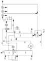
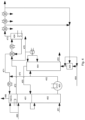
- Table 1 Number Description 101,201,301,401 Rinser of exhaust gases 102,202,302,402 NH 3 absorber (NH 3 -ABM) 103,203,303,403 Drip cooler 104,204,304,404 Carbonization column 105,205,305,405 Compressor 220,320,420 End cooler 221,225,226,227, Cooler 321, 325, 326, 327 Cooler 421,425,426,427 Cooler 222,322,422 Cross-flow heat exchanger 223,323,423 Heater 224,324,424 Regenerator of the absorption solution 150,250,350,450 Purified brine 151,251,351,451 Gases from the regeneration of condensates 152,252,352,452 Ammonia brine 270,370,470 Ammonia brine 154,254,354,454 Furnace gas 271,37
- the present invention encompasses increasing the degree of reaction of CO 2 contained within reaction gas by use of an additional section of absorptive gas washing (DeCO 2 zones), as a result of which CO 2 contained within the gas is washed out and may be used or returned to the process.
- Such procedure allows for limiting emission of CO 2 since the extracted CO 2 (273, 373, 473) is returned to the process, which lowers consumption of the resources.
- the special additional zone for removing CO 2 from the process gas is situated on the carbonization column (204).
- this zone may also be situated on several carbonization columns (204) used in a soda process.
- the DeCO 2 zone may also be present in the process line before ( Fig. 3 ) and/or after ( Fig. 4 ) the rinser of exhaust gases (301, 401) arising in the process of carbonation implemented on the carbonization column (304, 404) of the soda ash process.
- the process gas from the carbonization column introduced into the DeCO2 zone contains from 10 to 18 vol% of CO 2 and it is characterised by temperature T within a range from 40 to 55°C and pressure p falling within a range of 1-2 bar(a).
- An improvement in the efficiency of the rinser of exhaust gases (101, 201, 301, 401) in terms of removing CO 2 can be provided by placing in an existing soda installation an additional CO 2 removal zone (DeCO 2 ) or by introducing such a zone into a new soda installation.
- DeCO 2 additional CO 2 removal zone
- the DeCO 2 zone is placed in the lower part of the rinser (301), as it is presented on the layout shown in Fig. 3 .
- the CO 2 content of the gas delivered from the DeCO 2 zone is reduced to a level of 1 vol%.
- the DeCO 2 zone serves the function of a counter-flow absorption column, to which, depending on the specific implementation of the invention, to the lower part, gas with a specified carbon dioxide content is delivered.
- the regenerated solution of the absorbent (271, 371, 471) with a low degree of carbon dioxide saturation is introduced into the upper part of the DeCO 2 zone.
- the regenerated solution absorbs chemically carbon dioxide contained in the flowing gas, producing chemical compounds with impermanent bonds.
- the saturated carbon dioxide absorbent (272, 372, 472) leaving the DeCO 2 zone is heated in the heat exchanger (222, 322, 422) and/or heater (223, 323, 423) to a temperature within a range of 80-105 °C, using heat carriers listed in the present description, upon which it is directed to the desorption column (224, 324, 424).
- the primary component of the absorbent is ammonia and its compounds
- a part or the entirety of the stream (272, 372, 472) is directed to the carbonization column (204, 304, 404) via the heat exchanger (221, 321, 421).
- Thermal desorption of CO 2 (in a temperature depending on the used absorbent) from a saturated solution of the absorbent (272, 372, 472) takes place in the desorption column.
- the desorption of CO 2 with simultaneous regeneration of the solution in a desorption column (224, 324, 424) is implemented by delivering energy, particularly heat, in the form of water vapour in a rotavap, placed in its lower part or an apparatus with external circulation.
- gaseous CO 2 with a small amount of water vapour (273, 373, 473) is released from the top of the desorption column (224, 324, 424) via coolers (225, 325, 425) and/or (226, 326, 426) and (227, 327, 427) for providing maximum condensation of water vapour.
- any cooling agent known in the art is used in the coolers (225, 325, 425) and/or (226, 326, 426) and/or (227, 327, 427).
- the contact between the gaseous stream of CO 2 (273,373,473) and the cooling agent in these coolers is realised depending on a specific embodiment of the invention: in a membrane-based manner, meaning only with the exchange of heat, or in a membrane-less manner, meaning with the exchange of heat and mass.
- the gas contacts and mixes directly with the cooling agent.
- An advantage of such a solution is that the cooling agent absorbs the ammonia contained in gaseous CO 2 . Then, when it is not returned into the process into the compressor (205, 305, 405) or into its suction or into pumping, the stream freed of ammonia provides greater possibilities of its further use.
- the regenerated solution of the absorbent (271, 371, 471) Prior to returning to the DeCO 2 zone, the regenerated solution of the absorbent (271, 371, 471) is cooled down, which is realised using a cross-flow heat exchanger (222, 322, 422), which conveys heat to a stream of saturated solution (272, 372, 472). If such a need arises, the regenerated solution (271, 371, 471) is additionally cooled down using an additional cooler (220).
- a part of the stream of ammoniacal brine (252, 352, 452) in the form of a stream of ammoniacal brine (270, 370, 470) is directed respectively into the stream of a regenerated solution of the absorbent (271, 371, 471).
- a part of the stream of ammoniacal brine (272, 372, 472) in the form of a stream (274, 376, 476) is directed respectively into a stream of a regenerated solution of the absorbent (271, 371, 471).
- a significant element of the DeCO 2 zone is its fillings, poured or structural, whose task is to provide sufficiently developed contact surface of the liquid phase and the gaseous phase in an extent ensuring that the occurring mass exchange process could be sufficiently effective.
- Pall rings with diameters of 50 - 80 mm are such a filling.
- columns for the exchange of mass in the form of tube columns, mechanical columns, shelf columns (solutions in the form of a hood, a valve, a disc, a sieve, slatted overflow shelves), spray columns, surface columns, cascade columns, barbotage columns, sparge columns, cyclone columns or a column with a Venturi tube.
- CO 2 absorption processes which may be used in the presented solution depending on the mechanism are divided into the processes of physical and chemical absorption. Processes used in the method implemented according to the invention utilise absorption methods developed originally for the removal of acidic components such as H 2 S and CO 2 from natural gas, subsequently adapted to acquiring carbon dioxide from other gases. This technology enables the removal of approximately (75-96%) of CO 2 and obtaining a highly pure stream of CO 2 (with purity exceeding 99 vol%) .
- the process of absorption and desorption of CO 2 is conducted, depending on the parameters of the purified gas and the destination of the resulting gas, within a pressure range from 0.1 bar (a) to 6 bar(a) .
- Solutions containing ammonia originating from an external source and/or waste solutions or condensates originating from the production of soda are used as the absorption liquid.
- a certain amount of saturated carbon dioxide solution is directed to the top and/or to the central part of the carbonization column, and/or to a special separate desorption column.
- the gas from which CO 2 is removed contacts in counter-flow the stream of absorbent in the DeCO 2 absorption zone.
- ammonia and carbon dioxide form ammonium carbonate (NH 4 ) 2 CO 3 , ammonium bicarbonate NH 4 HCO 3 and ammonium carbamate NH 2 CO 2 NH 4 , which is discussed in detail above. Due to the fact that these reactions are exothermic reactions, the absorption process is preferably conducted in low temperatures, such as 10-50.
- the absorptive solution saturated with CO 2 is directed into the desorption column, where the solution regeneration process (CO 2 desorption process) occurs due to the impact of the delivered heat energy.
- the regeneration of such an ammonia solution saturated with carbon dioxide is conducted by introducing this stream into the existing circulation of the ammonia solution during the soda production process.
- a part or the entirety of the stream (272, 372, 472) in the form of a stream (274, 376, 476) may be directed into an existing circulation of the ammonia solution in the soda production process, where it is freed of a part of CO 2 contained within its composition, it regains the ability of further absorption of CO 2 and it is returned to the process by merging (not shown in the drawing) with the stream (271, 371, 471).
- the specific streams from the soda process containing NH 3 may be the source of NH 3 for supplementing the circulating solution.
- ammoniacal condensates or their solutions are used as such a liquid absorbent.
- solutions of chemical compounds such as amines, K 2 CO 3 , ionic liquids or compounds of amino acids are used as the absorptive substance (CO 2 absorbent) .
- compound solutions including, e.g. mixtures of inorganic salts/amine, ionic liquids/amine or inorganic salts/compounds of amino acids are used as a sorptive substance.
- the process of regenerating compound solutions (CO 2 desorption process), upon saturating in the DeCO 2 zone with carbon dioxide, is conducted in a special separate desorption column.
- the absorptive solution is subjected to regeneration by delivering a stream of heat providing proper temperature.
- the components of the absorbent meant to supply the DeCO 2 zone or supplement the currently used solution are directed directly into the stream (271, 371, 471).
- water vapour under a pressure up to 18 bar(a), more preferably water vapour under a pressure of 2 - 4 bar(a), is used as a useful heat carrier for regeneration.
- liquid and/or gaseous reaction streams from the soda production process and/or liquid and/or gaseous reaction streams and their mixtures with water vapour under a pressure up to 18 bar(a), and in particular under a pressure of 2 - 4 bar (a), are the heat carrier for regeneration.
- the stream of heat is delivered to a regeneration zone in the apparatus in a membrane-based manner by means of a rotavap.
- the stream of heat is delivered to a regeneration zone in the apparatus in a membrane-less manner.
- the working agent is released partially or entirely by cooling a combined stream of waste CO 2 gas and a heat carrier received from the upper part of the desorption column.
- water vapour as well as other heat carriers for desorption originate from the steam generator.
- water vapour as well as other heat carriers for regeneration originate from other streams present in the soda production process, including in particular, in specific embodiments of the invention:
- the mixture of water vapour and the remaining components of the absorption solution and waste carbon dioxide received from the desorption column is cooled down to release the highest possible amount of liquid components and ammonia, and to obtain a stream of recovered CO 2 of high purity.
- a cooled down, regenerated absorption solution (271, 371, 471), meaning an absorption solution with a temperature of 10-40°C.
- This solution is subjected to cooling, because it is pumped into the DeCO 2 zone from the bottom of the desorption column, where it is preheated to a temperature above 100°C, and in the case of amine solutions to a temperature of 105-125°C.
- the first cooling proceeds in the main cross-flow exchanger (222, 322, 422), in which a membrane-regenerated solution hands over its heat to a saturated solution (272, 372, 472) with a temperature from 35-60°C. Further cooling of the solution to a proper temperature (25-40°C) is conducted in the end cooler (220), where cooling water or other process streams commonly used in soda processes, whose examples are indicated below, are used for cooling.
- Another significant element of the CO 2 acquisition process is the cooling of the resulting stream of carbon dioxide to a temperature of 20-40°C in order to condense the moisture contained therein.
- a high amount of cooling water is used to cool down the stream of CO 2 .
- other process streams are used in the examples of practical implementation of the present invention, used during the production of soda by means of the Solvay method, with a temperature below 30°C, such as, for example, raw brine. These streams enable cooling the process streams to a temperature of 10-40°C.
- the process streams are used for partial (for example from 60°C to 50°C) cooling of CO 2 streams, which ultimately leads to decreasing the demand for cooling water. It is most justified to use process streams which are characterised by a low temperature (below 40°C), and for the requirements of the technological process it is desirable to heat them up to a higher temperature.
- a significant aspect of effectively conducting the CO 2 absorption process occurring with the release of heat is providing in the DeCO 2 zone a proper cooling arrangement, using cooling water or other process streams used during production in an installation whose detailed examples are indicated in the following part of the description.
- the stream of CO 2 acquired in a special desorption column (224, 324, 424) (272, 373, 473) upon proper preparation is introduced into the furnace gas directed into the carbonization column and/or into the baking soda installation and/or into the chemical sequestration and production of liquid and gaseous fuels and/or it is redirected to an external receiver as a final product, for example, to be used in food industry.
- the stream of CO 2 In the case of returning the resulting stream of CO 2 to the carbonization column, when the stream contains significant amounts of NH 3 , the stream of CO 2 , if it has the proper pressure of 3-6 bar (a), is delivered directly into the carbonization column. If this stream does not have a proper pressure, it is directed to the suction of furnace gas compressor (205, 305, 405) or between compression sections.
- absorption processes require cooling the stream of the absorption solution down to temperatures of 10-40°C and/or require cooling the stream of waste CO 2 to a level of 20-40°C and/or require cooling the process gas via using a cooling agent, to condense the moisture contained therein.
- cooling is implemented using cooling water or other process streams used for the production of soda, such as: a stream of raw brine with a temperature of 15 - 30°C, a stream of filtered mother liquor obtained upon separating sodium bicarbonate with a temperature of 15-40°C or a stream of salinated effluents with a temperature of 20-35°C.
- a gas rinsing section is used additionally in the DeCO 2 zone.
- the gas is in a membrane-less contact with the washing agent on a separate filling, consisting of fillings as described above.
- Such an ammonia content which is higher than 50 ppm is considered elevated.
- a sample washing agent used according to the invention is raw brine comprising sodium chloride, which is presented in Fig. 3 and Fig. 4 , diluted ammoniacal brine, an acidic absorbent or mother lye. Upon extracting the maximum possible amount of ammonia from gas, the washing agent is released from the DeCO 2 zone and it does not contact the actual CO 2 absorption zone.
Landscapes
- Chemical & Material Sciences (AREA)
- Engineering & Computer Science (AREA)
- General Chemical & Material Sciences (AREA)
- Environmental & Geological Engineering (AREA)
- Analytical Chemistry (AREA)
- Oil, Petroleum & Natural Gas (AREA)
- Chemical Kinetics & Catalysis (AREA)
- Biomedical Technology (AREA)
- Health & Medical Sciences (AREA)
- Organic Chemistry (AREA)
- Inorganic Chemistry (AREA)
- Treating Waste Gases (AREA)
- Gas Separation By Absorption (AREA)
- Carbon And Carbon Compounds (AREA)
Claims (18)
- Anlage zur Herstellung von Soda, umfassend mindestens eine Carbonisierungssäule (104, 204, 304, 404), mindestens einen Ammoniakabsorber (102, 202, 302, 402) zur Absorption von Ammoniak aus schwachen Gasen und einen Abgasspüler (101, 201, 301, 401), dadurch gekennzeichnet, dass sie ferner eine integrierte CO2-Rückgewinnungsanlage (DeCO2) umfasst, um den Restgasstrom, der aus der Carbonisierungssäule (204, 304, 404) im Rahmen des Soda-Verfahrens entfernt wurde, mit dem Absorptionsmittel in Berührung zu bringen, um durch die Absorption ein mit Kohlendioxid angereichertes Absorptionsmittel zu erhalten, und Desorption von zuvor absorbiertem Kohlendioxid in einer Desorptionssäule (224, 324, 424) der integrierten CO2-Rückgewinnungsanlage (DeCO2) mit gleichzeitiger Regeneration des Absorptionsmittels zu erzielen, wobei das desorbierte Kohlendioxid von der integrierten CO2-Rückgewinnungsanlage (DeCO2) zurück zur Carbonisierungssäule (204, 304, 404) eingeleitet wird,und wobei die integrierte CO2-Rückgewinnungsanlage (DeCO2) nach mindestens einer Carbonisierungssäule (204, 304, 404) im oberen Teil der mindestens einen Carbonisierungssäule (204) oder im unteren Teil des Abgasspülers zwischen mindestens einem Ammoniakabsorber (302) und der Zone des Abgasspülers (301) oder nach mindestens einem Ammoniakabsorber (402) im oberen Teil des Abgasspülers (401) angeordnet ist,und wobei die genannte integrierte CO2-Rückgewinnungsanlage (DeCO2) mit einer nach der Desorptionssäule (224, 324, 424) angeordneten Kühlzone versehen ist, wobei die Kühlzone mindestens einen Wärmetauscher (225, 226, 227 bis 425, 426, 427) umfasst, in dem der Strom von extrahiertem Kohlendioxid nach dessen Desorption mit Hilfe eines Kühlmittels gekühlt wird, wobei das Kühlmittel ist gewählt entweder aus Kühlwasser oder anderen im Soda-Verfahren verwendeten Prozessströmen, wie der Strom roher Salzlauge mit Temperatur von 15 - 30°C oder der Strom gefilterter Mutterlauge, die bei der Trennung von Natriumbicarbonat mit Temperatur von 15 - 40°C entsteht, oder ein Strom von salzhaltigem Abwasser mit Temperatur von 20 - 35°C.
- Ein Verfahren zur Rückgewinnung von CO2 im Soda-Verfahren, stattfindend in der Anlage nach Anspruch 1, umfassend die Schritte:a) Kontaktieren der Ströme von Restgasen, die aus der Carbonisierungssäule im Soda-Verfahren entfernt wurden, mit dem Absorptionsmittel, wobei im Absorptionsverfahren ein mit Kohlendioxid angereichertes Absorptionsmittel gewonnen wird,c) Desorption von zuvor absorbiertem Kohlendioxid bei gleichzeitiger Regenerierung des Absorptionsmittels,dadurch gekennzeichnet, dass
der Schritt des Kontaktierens in der integrierten CO2-Rückgewinnungsanlage (DECO2) durchgeführt wird, die in der Anlage zur Durchführung des Soda-Verfahrens nach mindestens einer Carbonisierungssäule (204, 304, 404), im oberen Teil mindestens einer Carbonisierungssäule (204) oder im unteren Teil des Abgasspülers zwischen mindestens einem Ammoniakabsorber (302) und der Zone des Abgasspülers (301) oder nach mindestens einem Ammoniakabsorber (402) im oberen Teil des Abgasspülers (401) angeordnet ist, und wobei die integrierte CO2-Rückgewinnungsanlage (DECO2) mit einer Kühlzone versehen ist, in der als Kühlmittel Kühlwasser oder andere im Soda-Verfahren verwendeten Prozessströme verwendet werden, wie ein Strom von roher Salzlauge mit Temperatur von 15 - 30°C oder ein Strom von gefilterter Mutterlauge die bei der Trennung von Natriumbicarbonat mit Temperatur von 15 bis 40°C, entsteht, oder ein Strom von salzhaltigem Abwasser mit Temperatur von 20 bis 35°C. - Das Verfahren zur CO2-Rückgewinnung im Soda-Verfahren nach Anspruch 2, wobei die zusätzliche CO2-Rückgewinnungsanlage (DECO2) im oberen Teil mindestens einer Carbonisierungssäule (204) angeordnet ist und Restgas mit Temperatur T von 40 - 55°C und Druck p von 1-2 bar in die zusätzliche CO2-Rückgewinnungsanlage (DECO2) eingeleitet wird.
- Das Verfahren zur CO2-Rückgewinnung im Soda-Verfahren nach Anspruch 2, wobei die zusätzliche CO2-Rückgewinnungsanlage (DECO2) in der Natronanlage angeordnet ist, und Restgas, das 15 bis 30 Vol.-% CO2 mit Temperatur T von 60 bis 90°C und unter Druck p von 1-2 bar enthält, in die CO2-Rückgewinnungsanlage (DECO2) eingeleitet wird.
- Das Verfahren zur CO2-Rückgewinnung im Soda-Verfahren nach Anspruch 2, wobei die zusätzliche CO2-Rückgewinnungsanlage (DECO2) nach mindestens einer Carbonisierungssäule (304) zwischen mindestens einem Ammoniakabsorber (302) und dem Bereich des Abgasspülers (301) angeordnet ist, und das in die zusätzliche CO2-Rückgewinnungsanlage (DECO2) eingeleitete Restgas Temperatur T von 20 bis 50°C aufweist und unter Druck von p = 1-2 bar steht.
- Das Verfahren zur CO2-Rückgewinnung im Soda-Verfahren nach Anspruch 2, wobei die zusätzliche CO2-Rückgewinnungsanlage nach mindestens einer Carbonisierungssäule (304) und nach mindestens einem Ammoniakabsorber (402) und direkt nach dem Bereich des Abgasspülers (401) angeordnet ist, und das in die zusätzliche CO2-Rückgewinnungsanlage (DECO2) eingeleitete Restgas Temperatur T von 20 bis 30°C aufweist und unter Druck p = 1-2 bar steht.
- Ein Verfahren nach einem der Ansprüche 2 - 6, wobei der Prozess der Extraktion von CO2 durch Absorption in der zusätzlichen CO2-Rückgewinnungsanlage (DECO2) stattfindet, wobei die Absorption eine physikalische oder eine chemische Absorption ist.
- Ein Verfahren nach Anspruch 7, wobei die Absorption eine chemische Absorption ist, die unter Druck im Bereich von 0,1-6 bar stattfindet, und dazu eine Ammoniak enthaltende Lösung, vorzugsweise eine Lösung mit einer Konzentration von 1-20%, als Absorptionsflüssigkeit verwendet wird.
- Das Verfahren nach Anspruch 8, wobei das in die zusätzliche CO2-Rückgewinnungsanlage (DECO2) eingeleitete Restgas im Gegenstrom mit dem Strom der Absorptionsflüssigkeit in Berührung kommt, und wobei innerhalb der zusätzlichen CO2-Rückgewinnungsanlage eine niedrige Temperatur im Bereich von 10 - 50°C aufrechterhalten wird.
- Das Verfahren nach Anspruch 9, wobei die Lösung der mit CO2 gesättigten Absorptionsflüssigkeit in die Desorptionssäule eingeleitet und aufgeheizt wird, wodurch die Absorptionsflüssigkeit regeneriert wird.
- Das Verfahren nach Anspruch 10, wobei die Absorptionsflüssigkeit regeneriert wird, indem ein Strom der Absorptionsflüssigkeit in den Kreislauf der Ammoniaklösung im Soda-Verfahren eingeleitet wird.
- Das Verfahren nach Anspruch 7, wobei die Absorptionsflüssigkeit aus einer Gruppe ausgewählt wird, die wässrige Lösungen umfasst, die Amine enthalten, vorzugsweise mit Konzentration von 1 % bis 50 %, wässrige Lösungen, die Verbindungen von Aminosäuren oder Produkte der Reaktion mit Aminosäuren enthalten, wie Kaliumglycinat, wässrige oder nichtwässrige Mehrkomponentenlösungen und wässrige oder nichtwässrige Lösungen, die Kaliumcarbonatsalze, wie K2CO3, in einer Menge von 20-40%, vorzugsweise 30% und 2-10% Amine in Kombination mit anderen anorganischen Salzen, die die Reaktion von CO2 zum Carbamat induzieren, enthalten, wobei besonders bevorzugt wässrige Lösungen sind, die Amine enthalten, insbesondere wässrige Lösungen, die Amine in Konzentration von 1% bis 50% enthalten.
- Das Verfahren nach einem der Ansprüche 10 - 12, wobei die Absorptionsflüssigkeit regeneriert wird, indem ein Strom der Absorptionsflüssigkeit in die Desorptionssäule eingeleitet wird, und wobei, möglicherweise vor dem Einleiten in die Desorptionssäule, die Lösung der mit CO2 gesättigten Absorptionsflüssigkeit erhitzt wird.
- Das Verfahren nach Anspruch 13, wobei die Absorptionsflüssigkeit in der Desorptionssäule, die unter Druck von 0,2 - 6 bar arbeitet, bei Temperatur von 70 - 250°C regeneriert wird und die Temperatur während des Regenerationsprozesses mit Hilfe eines Wärmeträgers unter Druck von bis zu 18 bar aufrechterhalten wird.
- Das Verfahren nach einem der Ansprüche 10 - 14, wobei der Strom von extrahiertem CO2, der die Desorptionssäule verlässt, unter Verwendung eines Kühlmittels gekühlt wird, um einen Strom von gebrauchtem CO2 mit hoher Reinheit zu erhalten.
- Das Verfahren nach Anspruch 15, wobei die Kühlung bis Temperatur von 10 - 40°C in einem Wärmetauscher (225, 325, 425) durchgeführt wird.
- Das Verfahren nach Anspruch 15 oder 16, wobei als Kühlmittel Prozessströme aus den Absorptionskühlern, die mit Wasserdampf unter Druck von bis zu 18 bar, vorzugsweise 2-4 bar, betrieben werden, und/oder flüssige und/oder gasförmige Reaktionsströme aus dem Sodaherstellungsverfahren und/oder flüssige und/oder gasförmige Reaktionsströme und/oder Wasser verwendet werden.
- Das Verfahren nach einem der Ansprüche 8-17, wobei die zusätzliche CO2-Rückgewinnungsanlage gegossene oder strukturelle Füllelemente enthält, um eine ausreichend große Kontaktfläche für die flüssige Phase des Absorptionsmittels mit der gasförmigen Phase des Prozessgases sicherzustellen.
Applications Claiming Priority (1)
| Application Number | Priority Date | Filing Date | Title |
|---|---|---|---|
| PL420590A PL420590A1 (pl) | 2017-02-21 | 2017-02-21 | Sposób ograniczania emisji CO2 w procesach sodowych |
Publications (3)
| Publication Number | Publication Date |
|---|---|
| EP3363523A1 EP3363523A1 (de) | 2018-08-22 |
| EP3363523B1 true EP3363523B1 (de) | 2024-02-07 |
| EP3363523B8 EP3363523B8 (de) | 2024-03-13 |
Family
ID=61971885
Family Applications (1)
| Application Number | Title | Priority Date | Filing Date |
|---|---|---|---|
| EP18157938.4A Active EP3363523B8 (de) | 2017-02-21 | 2018-02-21 | Verfahren zur begrenzung der co2-emissionen in einem sodaverfahren |
Country Status (3)
| Country | Link |
|---|---|
| EP (1) | EP3363523B8 (de) |
| ES (1) | ES2975763T3 (de) |
| PL (2) | PL420590A1 (de) |
Families Citing this family (6)
| Publication number | Priority date | Publication date | Assignee | Title |
|---|---|---|---|---|
| WO2021079875A1 (ja) * | 2019-10-23 | 2021-04-29 | Agc株式会社 | 混合原料の製造方法、溶融ガラスの製造方法、ガラス物品の製造方法、溶融ガラスの製造装置、及びガラス物品の製造装置 |
| CN112939031B (zh) * | 2021-01-13 | 2023-04-25 | 河南中源化学股份有限公司 | 高效碳化反应方法 |
| CN115581937B (zh) * | 2022-11-11 | 2025-09-05 | 中石化节能技术服务有限公司 | 一种评价精馏过程碳足迹中共生产品的分配方法 |
| CN116588961A (zh) * | 2023-04-23 | 2023-08-15 | 呈和科技股份有限公司 | 一种水滑石绿色生产工艺及装置 |
| CN116902996B (zh) * | 2023-09-15 | 2024-01-02 | 山东海化集团有限公司 | 一种碳化塔开塔方法 |
| CN119367964A (zh) * | 2024-07-02 | 2025-01-28 | 北京市飞达捷能气体分离技术有限公司 | 小苏打碳化塔工艺尾气中二氧化碳回收利用系统 |
Family Cites Families (10)
| Publication number | Priority date | Publication date | Assignee | Title |
|---|---|---|---|---|
| DE1567923B2 (de) * | 1967-08-29 | 1975-02-20 | Chemische Fabrik Kalk Gmbh, 5000 Koeln | Verfahren zur Herstellung von Natriumhydrogencarbonat |
| CA2574633C (en) | 2004-08-06 | 2010-08-10 | Eig, Inc. | Ultra cleaning of combustion gas including the removal of co2 |
| JP2011162404A (ja) | 2010-02-10 | 2011-08-25 | Tokuyama Corp | 炭酸ナトリウムの製造方法 |
| MY170412A (en) | 2010-03-09 | 2019-07-27 | Univ Sains Malaysia | Method for capturing and fixing carbon dioxide and apparatus for carrying out said method |
| CN102698585B (zh) * | 2012-06-29 | 2014-04-30 | 青岛碱业股份有限公司 | 回收锅炉烟道气中二氧化碳的方法 |
| EP2757071B1 (de) | 2013-01-17 | 2018-05-02 | General Electric Technology GmbH | Integriertes Kohlenstoffdioxidbeseitigungs- und Ammoniak-Soda-Verfahren |
| JP6071838B2 (ja) | 2013-10-18 | 2017-02-01 | 三菱重工業株式会社 | Co2又はh2s又はその双方の回収装置及び方法 |
| EP2910295B1 (de) | 2014-02-25 | 2016-08-31 | General Electric Technology GmbH | Anordnung und verfahren zur integrierten rauchgasbehandlung und natriumcarbonatherstellung |
| KR101644538B1 (ko) * | 2014-12-18 | 2016-08-02 | 재단법인 포항산업과학연구원 | 이산화탄소가 함유된 배가스로부터 이산화탄소를 포집 및 자원화하는 방법 및 장치 |
| FR3030477A1 (fr) | 2014-12-22 | 2016-06-24 | Solvay | Procede de production de carbonate/ bicarbonate de sodium |
-
2017
- 2017-02-21 PL PL420590A patent/PL420590A1/pl unknown
-
2018
- 2018-02-21 EP EP18157938.4A patent/EP3363523B8/de active Active
- 2018-02-21 PL PL18157938.4T patent/PL3363523T3/pl unknown
- 2018-02-21 ES ES18157938T patent/ES2975763T3/es active Active
Also Published As
| Publication number | Publication date |
|---|---|
| ES2975763T3 (es) | 2024-07-15 |
| EP3363523A1 (de) | 2018-08-22 |
| EP3363523B8 (de) | 2024-03-13 |
| PL3363523T3 (pl) | 2024-10-07 |
| PL420590A1 (pl) | 2018-08-27 |
Similar Documents
| Publication | Publication Date | Title |
|---|---|---|
| EP3363523A1 (de) | Verfahren zur begrenzung der co2-emissionen in einem sodaverfahren | |
| EP3384973B1 (de) | Verfahren zur rückgewinnung von kohlendioxid zur anreicherung der zur herstellung von natriumcarbonat und natriumhydrogencarbonat verwendeten gasströme durch ein solvay-verfahren | |
| CA2839326C (en) | Integrated carbon dioxide removal and ammonia-soda process | |
| EP3369707B1 (de) | Verfahren zur herstellung von natriumcarbonat mit integrierter kohlendioxidaufnahme durch ein ammoniakverfahren | |
| EP1781400B1 (de) | Reinigung von verbrennungsabgas mit entfernung von co2 | |
| CN107108247B (zh) | 用于生产碳酸钠/碳酸氢钠的方法 | |
| US20140356267A1 (en) | Process and system for capturing carbon dioxide from a gas stream | |
| CN105209157B (zh) | 废气中污染物的再生回收 | |
| EP2844369B1 (de) | Regenerative rückgewinnung von verunreinigungen aus abgasen | |
| AU2016308615B2 (en) | Process for capture of carbon dioxide and desalination | |
| MXPA00005733A (es) | Recuperacion de dioxido de carbono con mezclas de amina compuesta | |
| JP5989916B2 (ja) | アンモニアベース触媒による炭酸カリウム水溶液中でのco2吸収の速度向上 | |
| US8986640B1 (en) | System and method for recovering ammonia from a chilled ammonia process | |
| Kim et al. | CO2 absorption with low concentration ammonia liquor | |
| US4510124A (en) | System for recovery of CO2 from flue gases containing SO2 | |
| EP1958683A2 (de) | Verfahren zum Behandeln von Rauchgas bei Kraftwerken und anderen Anlagen | |
| RU2725319C2 (ru) | Способ получения диоксида углерода для производства кальцинированной соды аммиачным методом | |
| EA051532B1 (ru) | Способ и устройство для получения бикарбоната аммония в системе декарбонизации на основе аммиака | |
| SU638036A1 (ru) | Способ дистилл ции фильтровой жидкости содового производства | |
| CN118751008A (zh) | 一种钨冶炼废气资源化的碳捕集和利用系统及其方法 | |
| KR20180082038A (ko) | 2-amino-2-methylpropanol을 이용한 이산화탄소 포집 방법 |
Legal Events
| Date | Code | Title | Description |
|---|---|---|---|
| PUAI | Public reference made under article 153(3) epc to a published international application that has entered the european phase |
Free format text: ORIGINAL CODE: 0009012 |
|
| STAA | Information on the status of an ep patent application or granted ep patent |
Free format text: STATUS: THE APPLICATION HAS BEEN PUBLISHED |
|
| AK | Designated contracting states |
Kind code of ref document: A1 Designated state(s): AL AT BE BG CH CY CZ DE DK EE ES FI FR GB GR HR HU IE IS IT LI LT LU LV MC MK MT NL NO PL PT RO RS SE SI SK SM TR |
|
| AX | Request for extension of the european patent |
Extension state: BA ME |
|
| STAA | Information on the status of an ep patent application or granted ep patent |
Free format text: STATUS: REQUEST FOR EXAMINATION WAS MADE |
|
| 17P | Request for examination filed |
Effective date: 20190218 |
|
| RBV | Designated contracting states (corrected) |
Designated state(s): AL AT BE BG CH CY CZ DE DK EE ES FI FR GB GR HR HU IE IS IT LI LT LU LV MC MK MT NL NO PL PT RO RS SE SI SK SM TR |
|
| STAA | Information on the status of an ep patent application or granted ep patent |
Free format text: STATUS: EXAMINATION IS IN PROGRESS |
|
| 17Q | First examination report despatched |
Effective date: 20200605 |
|
| RAP1 | Party data changed (applicant data changed or rights of an application transferred) |
Owner name: CIECH R&D SP. Z O.O. |
|
| P01 | Opt-out of the competence of the unified patent court (upc) registered |
Effective date: 20230427 |
|
| GRAP | Despatch of communication of intention to grant a patent |
Free format text: ORIGINAL CODE: EPIDOSNIGR1 |
|
| STAA | Information on the status of an ep patent application or granted ep patent |
Free format text: STATUS: GRANT OF PATENT IS INTENDED |
|
| INTG | Intention to grant announced |
Effective date: 20230822 |
|
| GRAS | Grant fee paid |
Free format text: ORIGINAL CODE: EPIDOSNIGR3 |
|
| GRAA | (expected) grant |
Free format text: ORIGINAL CODE: 0009210 |
|
| STAA | Information on the status of an ep patent application or granted ep patent |
Free format text: STATUS: THE PATENT HAS BEEN GRANTED |
|
| AK | Designated contracting states |
Kind code of ref document: B1 Designated state(s): AL AT BE BG CH CY CZ DE DK EE ES FI FR GB GR HR HU IE IS IT LI LT LU LV MC MK MT NL NO PL PT RO RS SE SI SK SM TR |
|
| REG | Reference to a national code |
Ref country code: GB Ref legal event code: FG4D |
|
| REG | Reference to a national code |
Ref country code: DE Ref legal event code: R081 Ref document number: 602018064880 Country of ref document: DE Owner name: CIECH SODA POLSKA S.A., PL Free format text: FORMER OWNER: CIECH R&D SP. Z O.O., WARSZAWA, PL |
|
| REG | Reference to a national code |
Ref country code: CH Ref legal event code: PK Free format text: BERICHTIGUNG B8 Ref country code: CH Ref legal event code: EP |
|
| REG | Reference to a national code |
Ref country code: IE Ref legal event code: FG4D |
|
| REG | Reference to a national code |
Ref country code: DE Ref legal event code: R096 Ref document number: 602018064880 Country of ref document: DE |
|
| RAP2 | Party data changed (patent owner data changed or rights of a patent transferred) |
Owner name: CIECH SODA POLSKA S.A. |
|
| REG | Reference to a national code |
Ref country code: LT Ref legal event code: MG9D |
|
| REG | Reference to a national code |
Ref country code: NL Ref legal event code: FP |
|
| PG25 | Lapsed in a contracting state [announced via postgrant information from national office to epo] |
Ref country code: IS Free format text: LAPSE BECAUSE OF FAILURE TO SUBMIT A TRANSLATION OF THE DESCRIPTION OR TO PAY THE FEE WITHIN THE PRESCRIBED TIME-LIMIT Effective date: 20240607 |
|
| PG25 | Lapsed in a contracting state [announced via postgrant information from national office to epo] |
Ref country code: LT Free format text: LAPSE BECAUSE OF FAILURE TO SUBMIT A TRANSLATION OF THE DESCRIPTION OR TO PAY THE FEE WITHIN THE PRESCRIBED TIME-LIMIT Effective date: 20240207 |
|
| PG25 | Lapsed in a contracting state [announced via postgrant information from national office to epo] |
Ref country code: GR Free format text: LAPSE BECAUSE OF FAILURE TO SUBMIT A TRANSLATION OF THE DESCRIPTION OR TO PAY THE FEE WITHIN THE PRESCRIBED TIME-LIMIT Effective date: 20240508 |
|
| REG | Reference to a national code |
Ref country code: AT Ref legal event code: MK05 Ref document number: 1655014 Country of ref document: AT Kind code of ref document: T Effective date: 20240207 Ref country code: ES Ref legal event code: FG2A Ref document number: 2975763 Country of ref document: ES Kind code of ref document: T3 Effective date: 20240715 |
|
| PG25 | Lapsed in a contracting state [announced via postgrant information from national office to epo] |
Ref country code: HR Free format text: LAPSE BECAUSE OF FAILURE TO SUBMIT A TRANSLATION OF THE DESCRIPTION OR TO PAY THE FEE WITHIN THE PRESCRIBED TIME-LIMIT Effective date: 20240207 Ref country code: RS Free format text: LAPSE BECAUSE OF FAILURE TO SUBMIT A TRANSLATION OF THE DESCRIPTION OR TO PAY THE FEE WITHIN THE PRESCRIBED TIME-LIMIT Effective date: 20240507 |
|
| PG25 | Lapsed in a contracting state [announced via postgrant information from national office to epo] |
Ref country code: AT Free format text: LAPSE BECAUSE OF FAILURE TO SUBMIT A TRANSLATION OF THE DESCRIPTION OR TO PAY THE FEE WITHIN THE PRESCRIBED TIME-LIMIT Effective date: 20240207 |
|
| PG25 | Lapsed in a contracting state [announced via postgrant information from national office to epo] |
Ref country code: RS Free format text: LAPSE BECAUSE OF FAILURE TO SUBMIT A TRANSLATION OF THE DESCRIPTION OR TO PAY THE FEE WITHIN THE PRESCRIBED TIME-LIMIT Effective date: 20240507 Ref country code: NO Free format text: LAPSE BECAUSE OF FAILURE TO SUBMIT A TRANSLATION OF THE DESCRIPTION OR TO PAY THE FEE WITHIN THE PRESCRIBED TIME-LIMIT Effective date: 20240507 Ref country code: LT Free format text: LAPSE BECAUSE OF FAILURE TO SUBMIT A TRANSLATION OF THE DESCRIPTION OR TO PAY THE FEE WITHIN THE PRESCRIBED TIME-LIMIT Effective date: 20240207 Ref country code: IS Free format text: LAPSE BECAUSE OF FAILURE TO SUBMIT A TRANSLATION OF THE DESCRIPTION OR TO PAY THE FEE WITHIN THE PRESCRIBED TIME-LIMIT Effective date: 20240607 Ref country code: HR Free format text: LAPSE BECAUSE OF FAILURE TO SUBMIT A TRANSLATION OF THE DESCRIPTION OR TO PAY THE FEE WITHIN THE PRESCRIBED TIME-LIMIT Effective date: 20240207 Ref country code: GR Free format text: LAPSE BECAUSE OF FAILURE TO SUBMIT A TRANSLATION OF THE DESCRIPTION OR TO PAY THE FEE WITHIN THE PRESCRIBED TIME-LIMIT Effective date: 20240508 Ref country code: FI Free format text: LAPSE BECAUSE OF FAILURE TO SUBMIT A TRANSLATION OF THE DESCRIPTION OR TO PAY THE FEE WITHIN THE PRESCRIBED TIME-LIMIT Effective date: 20240207 Ref country code: AT Free format text: LAPSE BECAUSE OF FAILURE TO SUBMIT A TRANSLATION OF THE DESCRIPTION OR TO PAY THE FEE WITHIN THE PRESCRIBED TIME-LIMIT Effective date: 20240207 |
|
| PG25 | Lapsed in a contracting state [announced via postgrant information from national office to epo] |
Ref country code: PT Free format text: LAPSE BECAUSE OF FAILURE TO SUBMIT A TRANSLATION OF THE DESCRIPTION OR TO PAY THE FEE WITHIN THE PRESCRIBED TIME-LIMIT Effective date: 20240607 |
|
| PG25 | Lapsed in a contracting state [announced via postgrant information from national office to epo] |
Ref country code: SE Free format text: LAPSE BECAUSE OF FAILURE TO SUBMIT A TRANSLATION OF THE DESCRIPTION OR TO PAY THE FEE WITHIN THE PRESCRIBED TIME-LIMIT Effective date: 20240207 Ref country code: PT Free format text: LAPSE BECAUSE OF FAILURE TO SUBMIT A TRANSLATION OF THE DESCRIPTION OR TO PAY THE FEE WITHIN THE PRESCRIBED TIME-LIMIT Effective date: 20240607 Ref country code: LV Free format text: LAPSE BECAUSE OF FAILURE TO SUBMIT A TRANSLATION OF THE DESCRIPTION OR TO PAY THE FEE WITHIN THE PRESCRIBED TIME-LIMIT Effective date: 20240207 |
|
| REG | Reference to a national code |
Ref country code: CH Ref legal event code: PL |
|
| PG25 | Lapsed in a contracting state [announced via postgrant information from national office to epo] |
Ref country code: DK Free format text: LAPSE BECAUSE OF FAILURE TO SUBMIT A TRANSLATION OF THE DESCRIPTION OR TO PAY THE FEE WITHIN THE PRESCRIBED TIME-LIMIT Effective date: 20240207 |
|
| PG25 | Lapsed in a contracting state [announced via postgrant information from national office to epo] |
Ref country code: SM Free format text: LAPSE BECAUSE OF FAILURE TO SUBMIT A TRANSLATION OF THE DESCRIPTION OR TO PAY THE FEE WITHIN THE PRESCRIBED TIME-LIMIT Effective date: 20240207 |
|
| PG25 | Lapsed in a contracting state [announced via postgrant information from national office to epo] |
Ref country code: LU Free format text: LAPSE BECAUSE OF NON-PAYMENT OF DUE FEES Effective date: 20240221 |
|
| PG25 | Lapsed in a contracting state [announced via postgrant information from national office to epo] |
Ref country code: CH Free format text: LAPSE BECAUSE OF NON-PAYMENT OF DUE FEES Effective date: 20240229 |
|
| PG25 | Lapsed in a contracting state [announced via postgrant information from national office to epo] |
Ref country code: EE Free format text: LAPSE BECAUSE OF FAILURE TO SUBMIT A TRANSLATION OF THE DESCRIPTION OR TO PAY THE FEE WITHIN THE PRESCRIBED TIME-LIMIT Effective date: 20240207 Ref country code: CZ Free format text: LAPSE BECAUSE OF FAILURE TO SUBMIT A TRANSLATION OF THE DESCRIPTION OR TO PAY THE FEE WITHIN THE PRESCRIBED TIME-LIMIT Effective date: 20240207 |
|
| PG25 | Lapsed in a contracting state [announced via postgrant information from national office to epo] |
Ref country code: SK Free format text: LAPSE BECAUSE OF FAILURE TO SUBMIT A TRANSLATION OF THE DESCRIPTION OR TO PAY THE FEE WITHIN THE PRESCRIBED TIME-LIMIT Effective date: 20240207 |
|
| PG25 | Lapsed in a contracting state [announced via postgrant information from national office to epo] |
Ref country code: SM Free format text: LAPSE BECAUSE OF FAILURE TO SUBMIT A TRANSLATION OF THE DESCRIPTION OR TO PAY THE FEE WITHIN THE PRESCRIBED TIME-LIMIT Effective date: 20240207 Ref country code: SK Free format text: LAPSE BECAUSE OF FAILURE TO SUBMIT A TRANSLATION OF THE DESCRIPTION OR TO PAY THE FEE WITHIN THE PRESCRIBED TIME-LIMIT Effective date: 20240207 Ref country code: LU Free format text: LAPSE BECAUSE OF NON-PAYMENT OF DUE FEES Effective date: 20240221 Ref country code: EE Free format text: LAPSE BECAUSE OF FAILURE TO SUBMIT A TRANSLATION OF THE DESCRIPTION OR TO PAY THE FEE WITHIN THE PRESCRIBED TIME-LIMIT Effective date: 20240207 Ref country code: DK Free format text: LAPSE BECAUSE OF FAILURE TO SUBMIT A TRANSLATION OF THE DESCRIPTION OR TO PAY THE FEE WITHIN THE PRESCRIBED TIME-LIMIT Effective date: 20240207 Ref country code: CZ Free format text: LAPSE BECAUSE OF FAILURE TO SUBMIT A TRANSLATION OF THE DESCRIPTION OR TO PAY THE FEE WITHIN THE PRESCRIBED TIME-LIMIT Effective date: 20240207 Ref country code: CH Free format text: LAPSE BECAUSE OF NON-PAYMENT OF DUE FEES Effective date: 20240229 |
|
| REG | Reference to a national code |
Ref country code: DE Ref legal event code: R097 Ref document number: 602018064880 Country of ref document: DE |
|
| PG25 | Lapsed in a contracting state [announced via postgrant information from national office to epo] |
Ref country code: MC Free format text: LAPSE BECAUSE OF FAILURE TO SUBMIT A TRANSLATION OF THE DESCRIPTION OR TO PAY THE FEE WITHIN THE PRESCRIBED TIME-LIMIT Effective date: 20240207 |
|
| PG25 | Lapsed in a contracting state [announced via postgrant information from national office to epo] |
Ref country code: MC Free format text: LAPSE BECAUSE OF FAILURE TO SUBMIT A TRANSLATION OF THE DESCRIPTION OR TO PAY THE FEE WITHIN THE PRESCRIBED TIME-LIMIT Effective date: 20240207 |
|
| PLBE | No opposition filed within time limit |
Free format text: ORIGINAL CODE: 0009261 |
|
| STAA | Information on the status of an ep patent application or granted ep patent |
Free format text: STATUS: NO OPPOSITION FILED WITHIN TIME LIMIT |
|
| 26N | No opposition filed |
Effective date: 20241108 |
|
| PG25 | Lapsed in a contracting state [announced via postgrant information from national office to epo] |
Ref country code: IE Free format text: LAPSE BECAUSE OF NON-PAYMENT OF DUE FEES Effective date: 20240221 |
|
| PG25 | Lapsed in a contracting state [announced via postgrant information from national office to epo] |
Ref country code: IE Free format text: LAPSE BECAUSE OF NON-PAYMENT OF DUE FEES Effective date: 20240221 |
|
| PGFP | Annual fee paid to national office [announced via postgrant information from national office to epo] |
Ref country code: RO Payment date: 20250108 Year of fee payment: 8 |
|
| PGFP | Annual fee paid to national office [announced via postgrant information from national office to epo] |
Ref country code: ES Payment date: 20250303 Year of fee payment: 8 |
|
| PG25 | Lapsed in a contracting state [announced via postgrant information from national office to epo] |
Ref country code: SI Free format text: LAPSE BECAUSE OF FAILURE TO SUBMIT A TRANSLATION OF THE DESCRIPTION OR TO PAY THE FEE WITHIN THE PRESCRIBED TIME-LIMIT Effective date: 20240207 |
|
| PG25 | Lapsed in a contracting state [announced via postgrant information from national office to epo] |
Ref country code: CY Free format text: LAPSE BECAUSE OF FAILURE TO SUBMIT A TRANSLATION OF THE DESCRIPTION OR TO PAY THE FEE WITHIN THE PRESCRIBED TIME-LIMIT; INVALID AB INITIO Effective date: 20180221 |
|
| PG25 | Lapsed in a contracting state [announced via postgrant information from national office to epo] |
Ref country code: HU Free format text: LAPSE BECAUSE OF FAILURE TO SUBMIT A TRANSLATION OF THE DESCRIPTION OR TO PAY THE FEE WITHIN THE PRESCRIBED TIME-LIMIT; INVALID AB INITIO Effective date: 20180221 |
|
| PG25 | Lapsed in a contracting state [announced via postgrant information from national office to epo] |
Ref country code: TR Free format text: LAPSE BECAUSE OF FAILURE TO SUBMIT A TRANSLATION OF THE DESCRIPTION OR TO PAY THE FEE WITHIN THE PRESCRIBED TIME-LIMIT Effective date: 20240207 |
|
| PGFP | Annual fee paid to national office [announced via postgrant information from national office to epo] |
Ref country code: NL Payment date: 20260220 Year of fee payment: 9 |
|
| PGFP | Annual fee paid to national office [announced via postgrant information from national office to epo] |
Ref country code: GB Payment date: 20260222 Year of fee payment: 9 |
|
| PGFP | Annual fee paid to national office [announced via postgrant information from national office to epo] |
Ref country code: DE Payment date: 20260220 Year of fee payment: 9 |
|
| PGFP | Annual fee paid to national office [announced via postgrant information from national office to epo] |
Ref country code: BE Payment date: 20260220 Year of fee payment: 9 Ref country code: IT Payment date: 20260223 Year of fee payment: 9 |
|
| PGFP | Annual fee paid to national office [announced via postgrant information from national office to epo] |
Ref country code: FR Payment date: 20260222 Year of fee payment: 9 |
|
| PGFP | Annual fee paid to national office [announced via postgrant information from national office to epo] |
Ref country code: PL Payment date: 20260220 Year of fee payment: 9 |
|
| PGFP | Annual fee paid to national office [announced via postgrant information from national office to epo] |
Ref country code: BG Payment date: 20260220 Year of fee payment: 9 |