EP3363657B1 - Reifen - Google Patents
Reifen Download PDFInfo
- Publication number
- EP3363657B1 EP3363657B1 EP16855543.1A EP16855543A EP3363657B1 EP 3363657 B1 EP3363657 B1 EP 3363657B1 EP 16855543 A EP16855543 A EP 16855543A EP 3363657 B1 EP3363657 B1 EP 3363657B1
- Authority
- EP
- European Patent Office
- Prior art keywords
- stud
- hole
- side part
- central axis
- opening
- Prior art date
- Legal status (The legal status is an assumption and is not a legal conclusion. Google has not performed a legal analysis and makes no representation as to the accuracy of the status listed.)
- Active
Links
Images



Classifications
-
- B—PERFORMING OPERATIONS; TRANSPORTING
- B60—VEHICLES IN GENERAL
- B60C—VEHICLE TYRES; TYRE INFLATION; TYRE CHANGING; CONNECTING VALVES TO INFLATABLE ELASTIC BODIES IN GENERAL; DEVICES OR ARRANGEMENTS RELATED TO TYRES
- B60C11/00—Tyre tread bands; Tread patterns; Anti-skid inserts
- B60C11/14—Anti-skid inserts, e.g. vulcanised into the tread band
- B60C11/16—Anti-skid inserts, e.g. vulcanised into the tread band of plug form, e.g. made from metal, textile
Definitions
- the present invention relates to a tire having stud holes for stud insertion on the surface side of the tread.
- the anti-stud-loss performance and the demolding performance are mutually exclusive performances, and it has been difficult to satisfy both the performances at the same time.
- Patent Document 1 Japanese Unexamined Patent Application Publication No. 2010-70052 Reference is also made to FR 2438552 and JP 2013-180641 , which each disclose a tire according to the preamble of Claim 1 and to US 3842880 .
- the tire according to the present invention is set out in Claim 1 and has stud holes for stud insertion on the surface side the tread.
- the stud holes each have an opening side part on one side along the central axis of the stud hole, which opens on the surface of the tread, and a bottom side part on the other side along the central axis of the stud hole.
- the inner peripheral surface of the bottom side part is formed in a curved surface swelling outward away from the central axis of the stud hole, and the maximum diameter position of the inner peripheral surface of the bottom side part is located on the hole bottom surface side of the intermediate position between the boundary position of the opening side part and the bottom side part and the hole bottom surface.
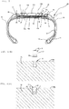
- the studdable tire 10 is comprised of a tire 1 having stud holes (stud recesses) 3 for insertion of studs (sometimes called spike pins) 2 on the surface side 14a of the tread 14 and studs 2 inserted in the stud holes 3 of the tire 1.
- the tire 1 includes beads 11, bead cores 11C, a carcass layer 12, belt layers 13a, 13b, a tread 14, sidewalls 15, and stud holes 3.
- the carcass layer 12 is a framework member disposed astride a pair of bead cores 11C disposed in the beads 11.
- the inside belt layer 13a and the outside belt layer 13b are disposed on the radially outside of the crown region of the carcass layer 12.
- the belt layers 13a and 13b are respectively formed with steel cords or stranded cords of organic fiber crossed at an angle of 20 to 70 degrees with respect to the equator of the tire. Therefore, the extension direction of the cords of the belt layer 13a located radially inside of the tire is crossed with the extension direction of the cords of the belt layer 13b located radially outside of the tire.
- a belt protection layer 13c which prevents the studs 2 sinking due to the collapse of the rubber below the studs 2 (radially inside of the tire) from piercing the outer belt layer 13b.
- the belt protection layer 13c is structured with cords of organic fiber or the like.
- the stud holes 3 are formed in the shoulder-side land portions 18 and the outer land portions 17B, for instance.
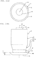
- the stud 2 having a body section 21, a pin section 22 disposed at one end along the central axis of the body section 21, and a flange section 23 disposed at the other end along the central axis of the body section 21, is a cylindrical member long along the central axis of the body section 21.
- the stud 2 is formed such that the central axis of the body section 21, the central axis of the pin section 22, and the central axis of the flange section 23 are aligned in a continuous straight line. And the continuous straight line constitutes the central axis 2C of the stud 2 (hereinafter referred to simply as "central axis 2C").
- the body section 21 has an upper part 21A located on the one-end side along the central axis 2C, an lower part 21B located on the other-end side along the central axis 2C, and a middle part 21C connecting the upper part 21A and the lower part 21B.
- the upper part 21A is formed in a cylindrical body having an equal shape of cross section orthogonal to the central axis 2C for the whole length along the central axis 2C.
- the lower part 21B is formed in a cylindrical body having an equal shape of cross section orthogonal to the central axis 2C for the whole length along the central axis 2C.
- sectional diameter of the upper part 21A and the sectional diameter of the lower part 21B is such that "sectional diameter of upper part 21A > sectional diameter of lower part 21B".
- the middle part 21C is formed in an inverted-cone-shape body whose diameter of cross section orthogonal to the central axis 2C gets gradually smaller from the upper part 21A side to the lower part 21B side.
- the pin section 22 is formed in a cylindrical body having an equal shape of cross section orthogonal to the central axis 2C for the whole length.
- the top-end surface 22t of the pin section 22 is formed in a flat surface orthogonal to the central axis 2C or a curved (convex) surface rising toward one end along the central axis 2C or a curved (concave) surface sinking toward the other end along the central axis 2C, for instance.
- the flange section 23 is so formed as to have the diameter being the greatest at the outer peripheral surface 24 and reducing from the one-end side toward the other-end side along the central axis 2C to connect to the other-end surface. And the maximum peripheral diameter position 24M of the outer peripheral surface 24 of the flange section 23 is located on the pin section 22 side of the position which is at 1/2 of the thickness T of the flange section along the central axis 2C.
- the stud 2 is embedded with the flange section 23 on the other-end side thereof first into the stud hole 3 formed in the surface 14a side of the tread 14 of the tire 1 driven by a not-shown stud driving machine.
- the stud hole 3 is formed as a hole extending from the surface 14a side of the tread 14 of the tire 1 toward the center (center axis of rotation of the tire 1) in the circle of the tire 1.
- the surface of the inner peripheral surface 36 of the bottom side part 32 extending along the central axis 3C of the stud hole 3 is formed in a curved surface swelling outward away from the central axis 3C.
- the curvature radius of the bottom-side curved surface 42 is greater than the curvature radius of the opening-side curved surface 41 (the curve of the bottom-side curved surface 42 being more acute than the curve of the opening-side curved surface 41).
- curvature radii of the inner peripheral surfaces and curved surfaces mentioned herein refer to the curvature radii of line segments running along the lateral surfaces in the depth direction of the stud hole 3 when the cross section of the stud hole 3 including the central axis 3C of the stud hole 3 is viewed from the side.
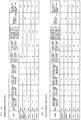
- the value range selected for the ratio C/B between the maximum diameter C of the bottom side part 32 and the diameter B of the middle area 33 is 1.0 ⁇ C/B ⁇ 1.6. Accordingly, stud holes 3 featuring both good demolding performance and good anti-stud-loss performance can be formed. Too small C/B will compromise anti-stud-loss performance, whereas too large C/B will compromise demolding performance. In the preferred embodiment, therefore, 1.0 ⁇ C/B ⁇ 1.6 is employed because C/B smaller than 1.0 was found to lower anti-stud-loss performance and C/B larger than 1.6 to lower demolding performance.
- the value range selected for the ratio R1/R2 between the curvature radius R1 of the opening-side curved surface 41 and the curvature radius R2 of the bottom-side curved surface 42 is 1.5 ⁇ R1/R2 ⁇ 100, and more preferably 2 ⁇ R1/R2 ⁇ 10.
- room temperature is 10 to 40°C, and 23°C is used herein. This temperature, which is the temperature for ordinary use of tires on icy or snowy roads has much bearing on the anti-stud-loss performance.
- the part which is subject to the greatest stress at demolding is the position on the side of the opening 3t of the stud hole 3 of the position X2, which is the height d of the bottom side part 32 apart from the boundary position 37 between the opening side part 31 and the bottom side part 32 of the stud hole 3. Therefore, the boundary surface 14X is not located at this part, and thus the boundary surface 14X is not subject to large stress at demolding. As a result, the rubber does not develop fracture at the boundary surface 14X, and the demolding performance improves.
- the description thus far has been given of an example of the stud hole 3 having the cross-sectional shape of the inner peripheral surface 36 intersecting with a plane orthogonal to the central axis 3C being a circle.
- the stud hole may have a cross-sectional shape other than a circle.
- the cross-sectional shape which is not subject to any particular limitation, may be elliptical, triangular, square, or of other shapes.
- the shape of the cross section of the stud hole 3 along the central axis 3C may be of different shapes on the left and right with respect to the central axis 3C at the center.
- the top rubber layer and the base rubber layer may each be a layer consisting of a plurality of rubber types, not necessarily a single layer consisting of a single rubber type. This is because the present invention holds its own as long as the top rubber layer and the base rubber layer satisfy the positional relationship of their elastic moduli at the boundary surface where they are adjacent to each other.
- the curvature radius of the opening-side curved surface and the curvature radius of the bottom-side curved surface are each a single curvature radius. That is, the opening-side curved surface and the bottom-side curved surface may each be a curved surface having a plurality of curvature radii and may be a curved surface having straight line portions in parts (e.g., midway, at the starting or ending portion).
- the bottom-side curved surface with a smaller curvature radius in the bottom side part of the stud hole increases the holding force for holding the flange section of the stud fitted in the stud hole. This makes it harder for the studs to fall out of the stud holes in the studdable tires in use.
Landscapes
- Engineering & Computer Science (AREA)
- Mechanical Engineering (AREA)
- Tires In General (AREA)
Claims (1)
- Reifen (1), der Folgendes aufweist:eine Lauffläche (14) mit Spikelöchern (3) zum Einsetzen von Spikes (2) auf der Oberflächenseite derselben,wobei, wenn keine Spikes in die Spikelöcher (3) eingesetzt sind, die Spikelöcher (3) jeweils einen öffnungsseitigen Teil (31) auf der einen Seite entlang der Mittelachse (3C) derselben, der sich auf der Oberfläche (14a) der Lauffläche (14) öffnet und einen sohlenseitigen Teil (32) auf der anderen Seite entlang der Mittelachse (3C) derselben, aufweisen,wobei eine innere Umfangsfläche (36) des sohlenseitigen Teils (32) in einer gekrümmten Fläche geformt ist, die von der Mittelachse (3C) des Spikelochs (3) weg nach außen anschwillt,wobei die Position des maximalen Durchmessers (36M) der inneren Umfangsfläche (36) des sohlenseitigen Teils (32) auf der Seite der Lochsohlenfläche (35) der Zwischenposition (39) zwischen der Begrenzungsposition (37) des öffnungsseitigen Teils (31) und des sohlenseitigen Teils (32) und der Lochsohlenfläche (35) angeordnet ist,wobei der Krümmungsradius (R1) einer gekrümmten Fläche (41) auf der Öffnungsseite, die eine gekrümmte Fläche (41) ist, die sich entlang der Mittelachse (3C) des Spikelochs (3) befindet, wobei sie zwischen der Position des maximalen Durchmessers (36M) und der Begrenzungsposition (37) angeordnet ist, größer ist als der Krümmungsradius (R2) einer gekrümmten Fläche (42) auf der Sohlenseite, die eine gekrümmte Fläche (42) ist, die sich entlang der Mittelachse (3C) des Spikelochs (3) erstreckt, wobei sie zwischen der Position des maximalen Durchmessers (36M) und der Lochsohlenfläche (35) des Spikelochs (3) angeordnet ist,dadurch gekennzeichnet, dassder öffnungsseitige Teil (31) einen Öffnungsbereich (34) aufweist, der in einer umgekehrten Kegelform ausgebildet ist, deren Durchmesser sich allmählich von der Seite der Oberfläche (14a) der Lauffläche (14) zu der Lochsohlenfläche (35) des Spikelochs (3) hin verringert, und der Öffnungsdurchmesser der Öffnung (3t) des Öffnungsbereichs (34) größer ist als der Querschnittsdurchmesser des sohlenseitigen Teils (32).
Applications Claiming Priority (2)
| Application Number | Priority Date | Filing Date | Title |
|---|---|---|---|
| JP2015204945A JP6579906B2 (ja) | 2015-10-16 | 2015-10-16 | タイヤ |
| PCT/JP2016/080590 WO2017065290A1 (ja) | 2015-10-16 | 2016-10-14 | タイヤ |
Publications (3)
| Publication Number | Publication Date |
|---|---|
| EP3363657A1 EP3363657A1 (de) | 2018-08-22 |
| EP3363657A4 EP3363657A4 (de) | 2018-11-14 |
| EP3363657B1 true EP3363657B1 (de) | 2020-04-01 |
Family
ID=58518390
Family Applications (1)
| Application Number | Title | Priority Date | Filing Date |
|---|---|---|---|
| EP16855543.1A Active EP3363657B1 (de) | 2015-10-16 | 2016-10-14 | Reifen |
Country Status (5)
| Country | Link |
|---|---|
| EP (1) | EP3363657B1 (de) |
| JP (1) | JP6579906B2 (de) |
| CN (1) | CN108367631A (de) |
| RU (1) | RU2697130C1 (de) |
| WO (1) | WO2017065290A1 (de) |
Families Citing this family (3)
| Publication number | Priority date | Publication date | Assignee | Title |
|---|---|---|---|---|
| JP7116659B2 (ja) * | 2018-10-19 | 2022-08-10 | Toyo Tire株式会社 | タイヤ |
| JP7085454B2 (ja) * | 2018-10-19 | 2022-06-16 | Toyo Tire株式会社 | タイヤ |
| DE102019216539A1 (de) * | 2019-10-28 | 2021-04-29 | Continental Reifen Deutschland Gmbh | Kombination aus einem Fahrzeugluftreifen und Spikes sowie Fahrzeugluftreifen |
Family Cites Families (15)
| Publication number | Priority date | Publication date | Assignee | Title |
|---|---|---|---|---|
| FI46349B (de) * | 1971-08-27 | 1972-11-30 | Patent Holding Ltd | |
| FR2438552A1 (fr) * | 1978-10-10 | 1980-05-09 | Antraigue Roger | Perfectionnement a un dispositif pour la pose de crampons dans les alveoles d'un pneumatique de vehicule automobile |
| FI123752B (fi) * | 2002-01-10 | 2013-10-15 | Nokian Renkaat Oyj | Ajoneuvon renkaan liukuestenasta |
| KR100543309B1 (ko) * | 2003-07-31 | 2006-01-20 | 한국타이어 주식회사 | 스노우 타이어 |
| FR2909037B1 (fr) * | 2006-11-28 | 2009-01-16 | Michelin Soc Tech | Ensemble pneumatique et crampons avec fixation par clipsage. |
| DE102007053609A1 (de) * | 2007-11-08 | 2009-05-14 | Continental Aktiengesellschaft | Fahrzeugluftreifen |
| JP5359145B2 (ja) * | 2008-09-18 | 2013-12-04 | 横浜ゴム株式会社 | 空気入りタイヤ |
| FR2957301B1 (fr) * | 2010-03-10 | 2012-07-13 | Ugigrip | Crampon pour un pneumatique |
| FR2982529B1 (fr) * | 2011-11-15 | 2014-01-03 | Michelin Soc Tech | Pneumatique cloute perfectionne. |
| JP2013180641A (ja) * | 2012-03-01 | 2013-09-12 | Bridgestone Corp | スパイクタイヤ |
| CN104955662B (zh) * | 2013-02-06 | 2017-08-11 | 倍耐力轮胎股份公司 | 装防滑钉的轮胎以及改善装防滑钉的轮胎性能的方法 |
| JP6095552B2 (ja) * | 2013-10-28 | 2017-03-15 | 東洋ゴム工業株式会社 | 空気入りタイヤ |
| JP5860451B2 (ja) * | 2013-12-27 | 2016-02-16 | 住友ゴム工業株式会社 | 冬用タイヤ |
| JP5892298B1 (ja) * | 2014-03-31 | 2016-03-23 | 横浜ゴム株式会社 | スタッドタイヤ |
| JP2015217621A (ja) * | 2014-05-19 | 2015-12-07 | 株式会社ブリヂストン | スパイクタイヤ用加硫金型、加硫方法及びスパイクタイヤ |
-
2015
- 2015-10-16 JP JP2015204945A patent/JP6579906B2/ja not_active Expired - Fee Related
-
2016
- 2016-10-14 RU RU2018117810A patent/RU2697130C1/ru active
- 2016-10-14 WO PCT/JP2016/080590 patent/WO2017065290A1/ja not_active Ceased
- 2016-10-14 CN CN201680074100.6A patent/CN108367631A/zh active Pending
- 2016-10-14 EP EP16855543.1A patent/EP3363657B1/de active Active
Non-Patent Citations (1)
| Title |
|---|
| None * |
Also Published As
| Publication number | Publication date |
|---|---|
| CN108367631A (zh) | 2018-08-03 |
| RU2697130C1 (ru) | 2019-08-13 |
| WO2017065290A1 (ja) | 2017-04-20 |
| EP3363657A1 (de) | 2018-08-22 |
| EP3363657A4 (de) | 2018-11-14 |
| JP6579906B2 (ja) | 2019-09-25 |
| JP2017074924A (ja) | 2017-04-20 |
Similar Documents
| Publication | Publication Date | Title |
|---|---|---|
| US8459321B2 (en) | Tread for tire including gum blocks with notches | |
| US8413695B2 (en) | Heavy duty tire with tread having closed end sipes and shallow axial grooves | |
| EP3363657B1 (de) | Reifen | |
| CN103998259A (zh) | 防滑钉轮胎 | |
| CN109789733B (zh) | 具有优化结构的轮胎 | |
| US10967679B2 (en) | Tire with a tread having reinforced sectors and self-maintaining recesses | |
| KR101917494B1 (ko) | 타이어 가류금형의 커프 성형용 블레이드와 이를 이용한 차량용 타이어 및 타이어 가류장치 | |
| CN109562652B (zh) | 重型卡车轮胎胎面和重型卡车轮胎 | |
| CN109774385B (zh) | 充气轮胎 | |
| US11446962B2 (en) | Tire | |
| CN111132855B (zh) | 具有改进的耐久性能的用于越野车辆的轮胎 | |
| EP3363658B1 (de) | Bespikebarer reifen und verfahren zur auswahl von kautschuk zur herstellung der oberen gummischicht und kautschuk zur herstellung der unteren gummischicht der lauffläche eines bespikebaren reifens | |
| CN107206639B (zh) | 轮胎成型用模具以及充气轮胎 | |
| JP5612391B2 (ja) | スタッダブルタイヤの製造方法、及び、タイヤモールド | |
| JP7293998B2 (ja) | 空気入りタイヤ及びタイヤ成形用金型 | |
| EP4249290B1 (de) | Reifen | |
| JP6532375B2 (ja) | タイヤ | |
| JP6539563B2 (ja) | タイヤ | |
| JP7103306B2 (ja) | タイヤ成形用金型 | |
| KR101747138B1 (ko) | 스터드 타이어의 트레드 블록 | |
| RU2781569C1 (ru) | Пресс-форма для шин и пневматическая шина | |
| JP2014169047A (ja) | 空気入りタイヤ | |
| CN107645992A (zh) | 包括由单根丝线形成的工作层的轮胎 |
Legal Events
| Date | Code | Title | Description |
|---|---|---|---|
| STAA | Information on the status of an ep patent application or granted ep patent |
Free format text: STATUS: THE INTERNATIONAL PUBLICATION HAS BEEN MADE |
|
| PUAI | Public reference made under article 153(3) epc to a published international application that has entered the european phase |
Free format text: ORIGINAL CODE: 0009012 |
|
| STAA | Information on the status of an ep patent application or granted ep patent |
Free format text: STATUS: REQUEST FOR EXAMINATION WAS MADE |
|
| 17P | Request for examination filed |
Effective date: 20180515 |
|
| AK | Designated contracting states |
Kind code of ref document: A1 Designated state(s): AL AT BE BG CH CY CZ DE DK EE ES FI FR GB GR HR HU IE IS IT LI LT LU LV MC MK MT NL NO PL PT RO RS SE SI SK SM TR |
|
| AX | Request for extension of the european patent |
Extension state: BA ME |
|
| A4 | Supplementary search report drawn up and despatched |
Effective date: 20181015 |
|
| RIC1 | Information provided on ipc code assigned before grant |
Ipc: B60C 11/16 20060101AFI20181009BHEP |
|
| DAV | Request for validation of the european patent (deleted) | ||
| DAX | Request for extension of the european patent (deleted) | ||
| GRAP | Despatch of communication of intention to grant a patent |
Free format text: ORIGINAL CODE: EPIDOSNIGR1 |
|
| STAA | Information on the status of an ep patent application or granted ep patent |
Free format text: STATUS: GRANT OF PATENT IS INTENDED |
|
| INTG | Intention to grant announced |
Effective date: 20191018 |
|
| GRAS | Grant fee paid |
Free format text: ORIGINAL CODE: EPIDOSNIGR3 |
|
| GRAA | (expected) grant |
Free format text: ORIGINAL CODE: 0009210 |
|
| STAA | Information on the status of an ep patent application or granted ep patent |
Free format text: STATUS: THE PATENT HAS BEEN GRANTED |
|
| AK | Designated contracting states |
Kind code of ref document: B1 Designated state(s): AL AT BE BG CH CY CZ DE DK EE ES FI FR GB GR HR HU IE IS IT LI LT LU LV MC MK MT NL NO PL PT RO RS SE SI SK SM TR |
|
| REG | Reference to a national code |
Ref country code: GB Ref legal event code: FG4D |
|
| REG | Reference to a national code |
Ref country code: CH Ref legal event code: EP Ref country code: AT Ref legal event code: REF Ref document number: 1250894 Country of ref document: AT Kind code of ref document: T Effective date: 20200415 |
|
| REG | Reference to a national code |
Ref country code: DE Ref legal event code: R096 Ref document number: 602016033280 Country of ref document: DE |
|
| REG | Reference to a national code |
Ref country code: IE Ref legal event code: FG4D |
|
| REG | Reference to a national code |
Ref country code: FI Ref legal event code: FGE |
|
| PG25 | Lapsed in a contracting state [announced via postgrant information from national office to epo] |
Ref country code: BG Free format text: LAPSE BECAUSE OF FAILURE TO SUBMIT A TRANSLATION OF THE DESCRIPTION OR TO PAY THE FEE WITHIN THE PRESCRIBED TIME-LIMIT Effective date: 20200701 |
|
| REG | Reference to a national code |
Ref country code: NL Ref legal event code: MP Effective date: 20200401 |
|
| REG | Reference to a national code |
Ref country code: LT Ref legal event code: MG4D |
|
| PG25 | Lapsed in a contracting state [announced via postgrant information from national office to epo] |
Ref country code: PT Free format text: LAPSE BECAUSE OF FAILURE TO SUBMIT A TRANSLATION OF THE DESCRIPTION OR TO PAY THE FEE WITHIN THE PRESCRIBED TIME-LIMIT Effective date: 20200817 Ref country code: LT Free format text: LAPSE BECAUSE OF FAILURE TO SUBMIT A TRANSLATION OF THE DESCRIPTION OR TO PAY THE FEE WITHIN THE PRESCRIBED TIME-LIMIT Effective date: 20200401 Ref country code: NO Free format text: LAPSE BECAUSE OF FAILURE TO SUBMIT A TRANSLATION OF THE DESCRIPTION OR TO PAY THE FEE WITHIN THE PRESCRIBED TIME-LIMIT Effective date: 20200701 Ref country code: NL Free format text: LAPSE BECAUSE OF FAILURE TO SUBMIT A TRANSLATION OF THE DESCRIPTION OR TO PAY THE FEE WITHIN THE PRESCRIBED TIME-LIMIT Effective date: 20200401 Ref country code: CZ Free format text: LAPSE BECAUSE OF FAILURE TO SUBMIT A TRANSLATION OF THE DESCRIPTION OR TO PAY THE FEE WITHIN THE PRESCRIBED TIME-LIMIT Effective date: 20200401 Ref country code: IS Free format text: LAPSE BECAUSE OF FAILURE TO SUBMIT A TRANSLATION OF THE DESCRIPTION OR TO PAY THE FEE WITHIN THE PRESCRIBED TIME-LIMIT Effective date: 20200801 Ref country code: SE Free format text: LAPSE BECAUSE OF FAILURE TO SUBMIT A TRANSLATION OF THE DESCRIPTION OR TO PAY THE FEE WITHIN THE PRESCRIBED TIME-LIMIT Effective date: 20200401 Ref country code: GR Free format text: LAPSE BECAUSE OF FAILURE TO SUBMIT A TRANSLATION OF THE DESCRIPTION OR TO PAY THE FEE WITHIN THE PRESCRIBED TIME-LIMIT Effective date: 20200702 |
|
| REG | Reference to a national code |
Ref country code: AT Ref legal event code: MK05 Ref document number: 1250894 Country of ref document: AT Kind code of ref document: T Effective date: 20200401 |
|
| PG25 | Lapsed in a contracting state [announced via postgrant information from national office to epo] |
Ref country code: HR Free format text: LAPSE BECAUSE OF FAILURE TO SUBMIT A TRANSLATION OF THE DESCRIPTION OR TO PAY THE FEE WITHIN THE PRESCRIBED TIME-LIMIT Effective date: 20200401 Ref country code: RS Free format text: LAPSE BECAUSE OF FAILURE TO SUBMIT A TRANSLATION OF THE DESCRIPTION OR TO PAY THE FEE WITHIN THE PRESCRIBED TIME-LIMIT Effective date: 20200401 Ref country code: LV Free format text: LAPSE BECAUSE OF FAILURE TO SUBMIT A TRANSLATION OF THE DESCRIPTION OR TO PAY THE FEE WITHIN THE PRESCRIBED TIME-LIMIT Effective date: 20200401 |
|
| PG25 | Lapsed in a contracting state [announced via postgrant information from national office to epo] |
Ref country code: AL Free format text: LAPSE BECAUSE OF FAILURE TO SUBMIT A TRANSLATION OF THE DESCRIPTION OR TO PAY THE FEE WITHIN THE PRESCRIBED TIME-LIMIT Effective date: 20200401 |
|
| REG | Reference to a national code |
Ref country code: DE Ref legal event code: R097 Ref document number: 602016033280 Country of ref document: DE |
|
| PG25 | Lapsed in a contracting state [announced via postgrant information from national office to epo] |
Ref country code: ES Free format text: LAPSE BECAUSE OF FAILURE TO SUBMIT A TRANSLATION OF THE DESCRIPTION OR TO PAY THE FEE WITHIN THE PRESCRIBED TIME-LIMIT Effective date: 20200401 Ref country code: RO Free format text: LAPSE BECAUSE OF FAILURE TO SUBMIT A TRANSLATION OF THE DESCRIPTION OR TO PAY THE FEE WITHIN THE PRESCRIBED TIME-LIMIT Effective date: 20200401 Ref country code: IT Free format text: LAPSE BECAUSE OF FAILURE TO SUBMIT A TRANSLATION OF THE DESCRIPTION OR TO PAY THE FEE WITHIN THE PRESCRIBED TIME-LIMIT Effective date: 20200401 Ref country code: DK Free format text: LAPSE BECAUSE OF FAILURE TO SUBMIT A TRANSLATION OF THE DESCRIPTION OR TO PAY THE FEE WITHIN THE PRESCRIBED TIME-LIMIT Effective date: 20200401 Ref country code: EE Free format text: LAPSE BECAUSE OF FAILURE TO SUBMIT A TRANSLATION OF THE DESCRIPTION OR TO PAY THE FEE WITHIN THE PRESCRIBED TIME-LIMIT Effective date: 20200401 Ref country code: AT Free format text: LAPSE BECAUSE OF FAILURE TO SUBMIT A TRANSLATION OF THE DESCRIPTION OR TO PAY THE FEE WITHIN THE PRESCRIBED TIME-LIMIT Effective date: 20200401 Ref country code: SM Free format text: LAPSE BECAUSE OF FAILURE TO SUBMIT A TRANSLATION OF THE DESCRIPTION OR TO PAY THE FEE WITHIN THE PRESCRIBED TIME-LIMIT Effective date: 20200401 |
|
| PLBE | No opposition filed within time limit |
Free format text: ORIGINAL CODE: 0009261 |
|
| STAA | Information on the status of an ep patent application or granted ep patent |
Free format text: STATUS: NO OPPOSITION FILED WITHIN TIME LIMIT |
|
| PG25 | Lapsed in a contracting state [announced via postgrant information from national office to epo] |
Ref country code: SK Free format text: LAPSE BECAUSE OF FAILURE TO SUBMIT A TRANSLATION OF THE DESCRIPTION OR TO PAY THE FEE WITHIN THE PRESCRIBED TIME-LIMIT Effective date: 20200401 Ref country code: PL Free format text: LAPSE BECAUSE OF FAILURE TO SUBMIT A TRANSLATION OF THE DESCRIPTION OR TO PAY THE FEE WITHIN THE PRESCRIBED TIME-LIMIT Effective date: 20200401 |
|
| 26N | No opposition filed |
Effective date: 20210112 |
|
| REG | Reference to a national code |
Ref country code: DE Ref legal event code: R119 Ref document number: 602016033280 Country of ref document: DE |
|
| PG25 | Lapsed in a contracting state [announced via postgrant information from national office to epo] |
Ref country code: SI Free format text: LAPSE BECAUSE OF FAILURE TO SUBMIT A TRANSLATION OF THE DESCRIPTION OR TO PAY THE FEE WITHIN THE PRESCRIBED TIME-LIMIT Effective date: 20200401 |
|
| REG | Reference to a national code |
Ref country code: CH Ref legal event code: PL |
|
| GBPC | Gb: european patent ceased through non-payment of renewal fee |
Effective date: 20201014 |
|
| PG25 | Lapsed in a contracting state [announced via postgrant information from national office to epo] |
Ref country code: MC Free format text: LAPSE BECAUSE OF FAILURE TO SUBMIT A TRANSLATION OF THE DESCRIPTION OR TO PAY THE FEE WITHIN THE PRESCRIBED TIME-LIMIT Effective date: 20200401 Ref country code: LU Free format text: LAPSE BECAUSE OF NON-PAYMENT OF DUE FEES Effective date: 20201014 |
|
| REG | Reference to a national code |
Ref country code: BE Ref legal event code: MM Effective date: 20201031 |
|
| PG25 | Lapsed in a contracting state [announced via postgrant information from national office to epo] |
Ref country code: DE Free format text: LAPSE BECAUSE OF NON-PAYMENT OF DUE FEES Effective date: 20210501 |
|
| PG25 | Lapsed in a contracting state [announced via postgrant information from national office to epo] |
Ref country code: GB Free format text: LAPSE BECAUSE OF NON-PAYMENT OF DUE FEES Effective date: 20201014 Ref country code: LI Free format text: LAPSE BECAUSE OF NON-PAYMENT OF DUE FEES Effective date: 20201031 Ref country code: BE Free format text: LAPSE BECAUSE OF NON-PAYMENT OF DUE FEES Effective date: 20201031 Ref country code: CH Free format text: LAPSE BECAUSE OF NON-PAYMENT OF DUE FEES Effective date: 20201031 |
|
| PG25 | Lapsed in a contracting state [announced via postgrant information from national office to epo] |
Ref country code: IE Free format text: LAPSE BECAUSE OF NON-PAYMENT OF DUE FEES Effective date: 20201014 |
|
| PG25 | Lapsed in a contracting state [announced via postgrant information from national office to epo] |
Ref country code: TR Free format text: LAPSE BECAUSE OF FAILURE TO SUBMIT A TRANSLATION OF THE DESCRIPTION OR TO PAY THE FEE WITHIN THE PRESCRIBED TIME-LIMIT Effective date: 20200401 Ref country code: MT Free format text: LAPSE BECAUSE OF FAILURE TO SUBMIT A TRANSLATION OF THE DESCRIPTION OR TO PAY THE FEE WITHIN THE PRESCRIBED TIME-LIMIT Effective date: 20200401 Ref country code: CY Free format text: LAPSE BECAUSE OF FAILURE TO SUBMIT A TRANSLATION OF THE DESCRIPTION OR TO PAY THE FEE WITHIN THE PRESCRIBED TIME-LIMIT Effective date: 20200401 |
|
| PG25 | Lapsed in a contracting state [announced via postgrant information from national office to epo] |
Ref country code: MK Free format text: LAPSE BECAUSE OF FAILURE TO SUBMIT A TRANSLATION OF THE DESCRIPTION OR TO PAY THE FEE WITHIN THE PRESCRIBED TIME-LIMIT Effective date: 20200401 |
|
| P01 | Opt-out of the competence of the unified patent court (upc) registered |
Effective date: 20230531 |
|
| PGFP | Annual fee paid to national office [announced via postgrant information from national office to epo] |
Ref country code: FR Payment date: 20231026 Year of fee payment: 8 Ref country code: FI Payment date: 20231020 Year of fee payment: 8 |
|
| PG25 | Lapsed in a contracting state [announced via postgrant information from national office to epo] |
Ref country code: FI Free format text: LAPSE BECAUSE OF NON-PAYMENT OF DUE FEES Effective date: 20241014 |
|
| PG25 | Lapsed in a contracting state [announced via postgrant information from national office to epo] |
Ref country code: FR Free format text: LAPSE BECAUSE OF NON-PAYMENT OF DUE FEES Effective date: 20241031 |