EP3363684A1 - Système d'éclairage adaptatif d'un véhicule tout-terrain - Google Patents
Système d'éclairage adaptatif d'un véhicule tout-terrain Download PDFInfo
- Publication number
- EP3363684A1 EP3363684A1 EP18154059.2A EP18154059A EP3363684A1 EP 3363684 A1 EP3363684 A1 EP 3363684A1 EP 18154059 A EP18154059 A EP 18154059A EP 3363684 A1 EP3363684 A1 EP 3363684A1
- Authority
- EP
- European Patent Office
- Prior art keywords
- light
- adaptive
- vehicle
- control unit
- lighting
- Prior art date
- Legal status (The legal status is an assumption and is not a legal conclusion. Google has not performed a legal analysis and makes no representation as to the accuracy of the status listed.)
- Granted
Links
Images


Classifications
-
- B—PERFORMING OPERATIONS; TRANSPORTING
- B60—VEHICLES IN GENERAL
- B60Q—ARRANGEMENT OF SIGNALLING OR LIGHTING DEVICES, THE MOUNTING OR SUPPORTING THEREOF OR CIRCUITS THEREFOR, FOR VEHICLES IN GENERAL
- B60Q1/00—Arrangement of optical signalling or lighting devices, the mounting or supporting thereof or circuits therefor
- B60Q1/02—Arrangement of optical signalling or lighting devices, the mounting or supporting thereof or circuits therefor the devices being primarily intended to illuminate the way ahead or to illuminate other areas of way or environments
- B60Q1/04—Arrangement of optical signalling or lighting devices, the mounting or supporting thereof or circuits therefor the devices being primarily intended to illuminate the way ahead or to illuminate other areas of way or environments the devices being headlights
- B60Q1/06—Arrangement of optical signalling or lighting devices, the mounting or supporting thereof or circuits therefor the devices being primarily intended to illuminate the way ahead or to illuminate other areas of way or environments the devices being headlights adjustable, e.g. remotely-controlled from inside vehicle
- B60Q1/08—Arrangement of optical signalling or lighting devices, the mounting or supporting thereof or circuits therefor the devices being primarily intended to illuminate the way ahead or to illuminate other areas of way or environments the devices being headlights adjustable, e.g. remotely-controlled from inside vehicle automatically
- B60Q1/085—Arrangement of optical signalling or lighting devices, the mounting or supporting thereof or circuits therefor the devices being primarily intended to illuminate the way ahead or to illuminate other areas of way or environments the devices being headlights adjustable, e.g. remotely-controlled from inside vehicle automatically due to special conditions, e.g. adverse weather, type of road, badly illuminated road signs or potential dangers
-
- B—PERFORMING OPERATIONS; TRANSPORTING
- B60—VEHICLES IN GENERAL
- B60Q—ARRANGEMENT OF SIGNALLING OR LIGHTING DEVICES, THE MOUNTING OR SUPPORTING THEREOF OR CIRCUITS THEREFOR, FOR VEHICLES IN GENERAL
- B60Q1/00—Arrangement of optical signalling or lighting devices, the mounting or supporting thereof or circuits therefor
- B60Q1/02—Arrangement of optical signalling or lighting devices, the mounting or supporting thereof or circuits therefor the devices being primarily intended to illuminate the way ahead or to illuminate other areas of way or environments
- B60Q1/24—Arrangement of optical signalling or lighting devices, the mounting or supporting thereof or circuits therefor the devices being primarily intended to illuminate the way ahead or to illuminate other areas of way or environments for lighting other areas than only the way ahead
-
- B—PERFORMING OPERATIONS; TRANSPORTING
- B60—VEHICLES IN GENERAL
- B60Q—ARRANGEMENT OF SIGNALLING OR LIGHTING DEVICES, THE MOUNTING OR SUPPORTING THEREOF OR CIRCUITS THEREFOR, FOR VEHICLES IN GENERAL
- B60Q2300/00—Indexing codes for automatically adjustable headlamps or automatically dimmable headlamps
- B60Q2300/20—Indexing codes relating to the driver or the passengers
- B60Q2300/23—Driver's line of sight
-
- B—PERFORMING OPERATIONS; TRANSPORTING
- B60—VEHICLES IN GENERAL
- B60Q—ARRANGEMENT OF SIGNALLING OR LIGHTING DEVICES, THE MOUNTING OR SUPPORTING THEREOF OR CIRCUITS THEREFOR, FOR VEHICLES IN GENERAL
- B60Q2300/00—Indexing codes for automatically adjustable headlamps or automatically dimmable headlamps
- B60Q2300/30—Indexing codes relating to the vehicle environment
- B60Q2300/33—Driving situation
-
- B—PERFORMING OPERATIONS; TRANSPORTING
- B60—VEHICLES IN GENERAL
- B60Q—ARRANGEMENT OF SIGNALLING OR LIGHTING DEVICES, THE MOUNTING OR SUPPORTING THEREOF OR CIRCUITS THEREFOR, FOR VEHICLES IN GENERAL
- B60Q2300/00—Indexing codes for automatically adjustable headlamps or automatically dimmable headlamps
- B60Q2300/40—Indexing codes relating to other road users or special conditions
- B60Q2300/45—Special conditions, e.g. pedestrians, road signs or potential dangers
-
- B—PERFORMING OPERATIONS; TRANSPORTING
- B60—VEHICLES IN GENERAL
- B60Q—ARRANGEMENT OF SIGNALLING OR LIGHTING DEVICES, THE MOUNTING OR SUPPORTING THEREOF OR CIRCUITS THEREFOR, FOR VEHICLES IN GENERAL
- B60Q2800/00—Features related to particular types of vehicles not otherwise provided for
- B60Q2800/20—Utility vehicles, e.g. for agriculture, construction work
Definitions
- the invention relates to an adaptive light system of an all-terrain vehicle, with a lighting device controllable with regard to emission characteristics and / or light intensity.
- Such a lighting system in the form of a device for adjusting a lighting for a road vehicle is for example in the DE 10 2010 040 650 A1 described. Accordingly, a control unit based on road course information determines the visibility of preceding curves in order to adjust the illumination depending on the ascertained visibility such that the least possible dazzling of the oncoming traffic is ensured.
- the known lighting system is intended primarily for use in traffic.
- the adaptive lighting system of an off-road vehicle comprises a lighting device which is controllable with regard to emission characteristics and / or light intensity, and a control unit which determines the emission characteristic and / or light intensity by controlling the lighting device in accordance with a determined line of vision of a vehicle operator, determined extraneous light influences, an ascertained relative position of an off-road Foreign vehicle and / or cartographic location information.
- the lighting can be adapted to the current focus of attention of the vehicle operator by evaluating the current line of sight of the vehicle operator, so that in particular an annoying manual setting of a desired illumination area of an ambient or work lighting of the off-road vehicle during off-road use can be omitted, whereas by observing possible extraneous light influences Additionally or alternatively, a consideration of the existing residual light or other (artificial) light sources is possible. On the basis of the determined relative positions of all-terrain vehicles, their possible entry into the illumination area of the ambient or work lighting of the all-terrain vehicle can also be predicted so that they can be included in the respective lighting situation.
- the surroundings of the off-road course to be traveled can also be taken into account in such a way that an adjacent street, localities or the like is excluded by suitable adaptation of the emission characteristic and / or light intensity in order to avoid unwanted glare from the illumination area of the ambient or work lighting.
- the cartographic location information relevant in this respect can be recorded offline by means of a planning software and then uploaded to the control unit of the adaptive lighting system.
- the all-terrain vehicle may be of any type, conceivable inter alia a use of the adaptive lighting system in agricultural tractors, harvesters, forage harvesters, forestry machines, construction machinery or the like.
- the lighting device is preferably an ambient or work lighting of the all-terrain vehicle and / or a lighting provided within a driver's cab, in particular in the form of illuminable control and display elements or cabin interior lighting.
- the environment or work lighting may have multiple headlights, which are mounted, inter alia, in the roof area of the cab and allow a flat or overlapping illumination of the terrain vehicle surrounding terrain.
- these can be switched individually and with regard to their luminous intensity be changeable.
- the individual headlamps additionally have optical devices for changing the emission characteristic, thus their emission angle or the light distribution dependent on the emission angle.
- the optical devices can be formed either by electrically controllable optical systems (diaphragms or lens systems) or else by the light source itself. In the latter case, this typically consists of a segmented LED matrix in which individual matrix segments can be switched on and off by the control unit and modified in terms of their luminous intensity.
- the adaptive lighting system can comprise a further lighting device encompassed by an attachment or additional device of the all-terrain vehicle, in particular in the form of its own ambient or work lighting.
- the further illumination device in conjunction with the illumination device of the all-terrain vehicle is controlled by the control unit such that a desired overall illumination situation can be achieved.
- the control unit can reduce the luminous intensity in areas lying outside the viewing direction and / or areas prone to glare by adapting the emission characteristic and / or the light intensity of the illumination device.
- the lighting can be limited to lying in the attention focus of the vehicle operator areas, but it is also a risk of glare of in the illumination area of a working or ambient lighting of the off-road vehicle entrancing off-road vehicles reduced, which can be easily judged on the basis of the determined ambient light influences and / or the determined relative position of the respective off-highway foreign vehicle.
- the extraneous light influences (or stray light influences) can be caused here due to own environment or work lights of all-terrain vehicles.
- control device determines the viewing direction of the vehicle operator by optically detecting the eye position and / or the head posture.
- Such devices are known for example from the automotive sector in the context of systems for falling asleep and comprise a camera, which is integrated, for example, in a rearview mirror or a housing enclosed by the rearview mirror within a passenger compartment, by means of an associated image processing software, the driver's degree of fatigue of this characteristic To derive signs of sensed movement of the eyelids or pupils.
- the control unit preferably has a data interface for the wireless reception of position information transmitted by the off-highway foreign vehicle, wherein the control unit determines the relative position by comparison with position information related to the agricultural vehicle.
- the assessment or determination of the relative position takes place here on the basis of a polar coordinate system in which the all-terrain vehicle forms the origin of the coordinates.
- the communication carried out by the data interface with the all-terrain vehicle can take place via an existing mobile radio network, either directly between the vehicles or via a central data server or a data cloud. It is also possible for the control unit to determine the relative position by optical environmental detection on the basis of a distinction between moving and stationary objects carried out by means of image pattern recognition.
- the detection of the off-road vehicle related position information by means of a satellite-based navigation system.
- the satellite-based navigation system can in this case be permanently installed in the agricultural vehicle, but it can also be a mobile navigation unit, for example as part of a tablet computer carried by the vehicle operator, a mobile telephone or the like.
- the determined position information is wirelessly transmitted to the control unit, for example via an LTE or WLAN connection.
- the control unit controls the illumination device in the case of a reduction of the light intensity in such a way that a predetermined residual luminosity level is not undershot.
- the maintenance of a certain residual luminous intensity prevents just in connection with illuminable control and display elements that the vehicle operator falsely given the impression that the associated functions are disabled or inactive. Such an impression can result when the instrument illumination is completely switched off.
- Similar considerations apply with respect to the case that an ambient or work lighting of the off-road vehicle is turned off, which may lead to possible irritation in the vehicle operator due to the delayed adaptability of the eye.
- the residual luminosity, as well as a desired Maximum luminosity, this can be specified manually by the vehicle operator.
- control unit is responsible for determining the extraneous light influences by means of an ambient light and / or image sensor.
- the light and / or image sensor can either be one or more cameras arranged in the roof area of the driver's cab, in particular a panoramic or omnidirectional camera, or light-sensitive sensor elements or individual cameras arranged distributed along an outer side of the all-terrain vehicle.
- the ambient light and / or image sensor makes it possible to determine the light distribution in the surroundings of the all-terrain vehicle, for which purpose it can detect the extraneous light influences with regard to emission characteristics and / or light intensity.
- This allows a particularly accurate adaptation of the emission characteristic and / or light intensity of the illumination device of the all-terrain vehicle, for example, to achieve a constant illumination of the environment in the area of the all-terrain vehicle by appropriate inclusion of the determined light distribution of extraneous light influences.
- control unit can make a classification of extraneous light influences by referencing with cartographic location information, wherein an activation of the illumination device is omitted insofar as it follows from the classification that the extraneous light influences originate from a stationary object.
- a glare hazard is not given here, for example, it may be a street or courtyard lighting.
- the performed classification allows a reliable differentiation of such extraneous light influences compared to those that originate from other vehicles and where there is a corresponding risk of glare.
- the classification itself can be done by matching the cartographic location information with position information provided by a satellite-based navigation system.
- each equipped with the adaptive lighting system off-road vehicles can form a fleet, the individual fleet vehicles via a wireless data communication with each other in exchange to the emission characteristics and / or light intensities associated work or ambient lighting in In the sense of optimal or homogeneous illumination of a terrain surface to be processed or to avoid mutual glare with each other vote or adapt.
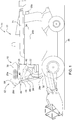
- Fig. 1 shows an embodiment of the adaptive light system according to the invention, this being described below with reference to the in Fig. 2 illustrated block diagram should be described.
- the adaptive lighting system 10 is part of a four-wheeled vehicle 14 designed as a forage harvester 14.
- the off-highway vehicle 14 can also be of any other type, conceivable inter alia being the use of the adaptive lighting system 10 in agricultural tractors, harvesting machines, forestry machines, construction machines or the like ,
- the adaptive light system 10 includes an in Fig. 2 illustrated illumination device 16, which can be controlled by an electronic control unit 18 in terms of emission characteristics and / or light intensity.
- the lighting device 16 is an environment or work lighting 20 of the forage harvester 12 and a lighting provided within a driver's cabin 22 in the form of illuminable control and display elements 24 or a cabin interior lighting 26 Fig. 1 the environment or work lights 20 a plurality of headlights 28a, 28b, 28c, 28d, 28e, which are mounted in a roof area 30 and on a front apron 32 of the cab 22 and on a body 34 of the forage harvester 12 and a flat or overlapping illumination of the field chopper 12 surrounding terrain or field surface 36 allow.
- At least the headlights 28a, 28b, 28c are individually switchable for adapting the emission characteristic and / or light intensity on the part of the control unit 18 as well as changeable in terms of their luminosity.
- On the side facing away from the viewer of the forage harvester 12 are further, corresponding to the side-mounted headlights 28a, 28b headlights.
- the headlights 28a, 28b, 28c have optical devices 38a, 38b, 38c adjacent to the actual light source (halogen or gas discharge lamp, LEDs or the like) for changing the emission characteristic, ie the emission angle or the light distribution dependent on the emission angle.
- optical devices 38a, 38b, 38c which are not shown in detail are formed either by electrically controllable optical systems (diaphragms or lens systems) or else by the luminous means itself. In the latter case, this consists of a segmented LED matrix, in which individual matrix segments on the part of the control unit 18 on and off and can be changed in terms of their luminosity. This is illustrated by way of example for the spotlight 28a arranged laterally in the roof area 30 of the driver's cab 22.
- a camera 40 for optical detection of the eye position and / or the head posture of a vehicle operator 42.
- the information thus obtained is supplied to the control unit 18 to determine the current viewing direction of the vehicle operator 42 by means of image processing software.
- the camera 40 is integrated in a rearview mirror 44 or a housing 46 surrounded by the rearview mirror 44.
- control unit 18 has a data interface 48 for the wireless reception of position information transmitted by an off-road vehicle 50 (see also FIG Fig. 3 ).
- the position information transmitted by the all-terrain vehicle 50 is located in a data cloud 52 and can be called from there via the data interface 48 via an existing mobile radio network.
- the control unit 18 determines a relative position of the forage harvester 12 relative to the off-highway foreign vehicle 50, for which purpose it performs a comparison with position information related to the forage harvester 12.
- the assessment or determination of the relative position takes place here on the basis of a polar coordinate system in which the forage harvester 12 forms the origin of the coordinates.
- the position information related to the forage harvester 12 is detected by means of a satellite-based navigation system 54.
- the satellite-based navigation system 54 is either permanently installed in the forage harvester 12 or designed as a mobile navigation unit 56. The latter is part of a mobile phone of the vehicle operator 42, wherein the determined position information is wirelessly transmitted to the control unit 18 via an LTE connection 60 produced by means of a mobile radio interface 58.
- control unit 18 is connected to an ambient light and / or image sensor 62 for determining possible extraneous light influences.
- the light and / or image sensor 62 is one in the roof area 30 of the driver's cab Notwithstanding this, it may also be arranged along an outer side of the forage harvester 12 distributed (not shown) photosensitive sensor elements or individual cameras act.
- the environment-detecting light and / or image sensor 62 makes it possible to determine the light distribution in the vicinity of the forage harvester 12, for which purpose it detects the extraneous light influences with regard to their emission characteristic and / or light intensity.
- the information determined in this way in relation to the instantaneous line of sight of the vehicle operator 42, possible extraneous light influences and / or the relative position of the off-highway foreign vehicle 50 are supplied to the control unit 18 in the form of corresponding data signals, the control unit 18 the emission characteristic and / or light intensity by driving the illumination device 16 adjusted in accordance with the information obtained.
- a first control routine executed by the control unit 18 provides for reducing the luminous intensity in areas outside the viewing direction of the vehicle operator 42 by adapting the emission characteristic and / or the light intensity of the illumination device 16.
- control unit 18 reduces the luminosity of the rear headlamp 28c, if, due to the determined line of sight, the vehicle operator 42 has not looked back for some time, which is done either by turning the head or by looking into the rearview mirror 44 can. On the other hand, the vehicle operator 42 directs his Looking back to the rear, the control unit 18 increases the luminosity of the rear headlamp 28c to its original value.
- the first control routine leads to a saving of electrical energy, since the illumination can be limited to areas lying in the attention focus of the vehicle operator 42. This is particularly important in the case of battery-operated systems, since the optimum use of the available battery capacity is of particular importance here.
- an adaptation of the emission characteristic and / or light intensity of the illumination device 16 takes place in accordance with cartographic location information.
- cartographic location information allows a targeted planning in particular of a desired illumination area of the environment or work lighting 20 along an off-road course to be traveled. It is envisaged that obstacles or danger spots (rocks, ditches and the like) are mapped and highlighted visibly upon reaching their associated position by additional illumination. The latter is performed by matching with the position information provided by the satellite-based navigation system 54. Also, the environment of the terrain to be traveled is considered to the effect that an adjacent street, localities or the like to avoid unwanted glare from the illumination of the ambient or work lighting are excluded by suitable adaptation of the emission and / or light intensity.
- the cartographic location information relevant in this respect can be recorded offline by means of a planning software and then uploaded to the control unit 18 of the adaptive light system 10.
- a third control routine executed by the control unit 18 envisages reducing the luminous intensity in areas prone to glare by adapting the emission characteristic and / or the light intensity of the illumination device 16 in order to reduce the risk of glare from off-road vehicles entering the illumination area of the forage harvester 12.
- FIG. 3 3 shows an exemplary light scene in the case of a cross-country vehicle 50 traveling next to the forage harvester 12 in the form of a vehicle combination 72 consisting of a loader wagon 68 and an agricultural tractor 70.
- a vehicle combination 72 consisting of a loader wagon 68 and an agricultural tractor 70.
- the illumination area of the Environment and work lights 20 of the forage harvester 12 is specifically expanded to the loader wagons 68.
- the control unit 18 determines from the position information received via the data interface 48 from the data cloud 52 the current relative position of the loading wagon 68 relative to the forage harvester 12 or an ejection manifold 74 provided thereon.
- the agricultural tractor 70 has its own (not shown) ) Environment or work lighting, wherein the determined by means of the ambient light and / or image sensor 62 light distribution is included by the control unit 18 in the adjustment of the emission and / or light intensity of the illumination device 16 in the general lighting situation such that on the one hand optimal or homogeneous illumination of the environment or field surface 36 in the field of forage harvester 12 ensured and on the other dazzling of a vehicle operator 76 of the agricultural tractor 70 is excluded.
- the agricultural tractor 70 is located in a darkened area 80, which is recessed by the lighting device 16 and follows the movement of the agricultural tractor 70 in accordance with the respectively determined relative position.
- control unit 18 carries out a classification of the extraneous light influences by referencing with cartographic location information, wherein an activation of the illumination device 16 is omitted insofar as it results from the classification that the extraneous light influences originate from a stationary object 80.
- a glare hazard is not given here, for example, it may be a street or courtyard lighting.
- the classification carried out allows a reliable differentiation of such extraneous light influences against those which originate from other vehicles and in which a corresponding glare hazard exists.
- the classification itself can be done by matching the cartographic location information stored in a storage unit 82 with the location information provided by the satellite-based navigation system 54.
- the three control routines may run side by side or alternatively in the control unit 18.
- a corresponding selection of the desired control routine can be made by the vehicle operator 42 via an operator terminal 84 in communication with the control unit 18, via which the headlights 28a, 28b, 28c to be included in the lighting situation can also be preselected manually.
- an automatic mode can be provided in which the illumination is adapted to the current attention focus of the vehicle operator 42 by evaluating the current viewing direction of the vehicle operator 42, so that in particular annoying manual adjustment of a desired illumination range of the ambient or working lighting 20 of the forage harvester 12 during the Fieldwork can be omitted.
- the adaptation of the lighting for the purpose the consideration of the existing residual light or other (artificial) light sources in accordance with the determined extraneous light influences modified by the control unit 18.
- the vehicle operator has the option of manually setting a desired emission characteristic and / or light intensity via the operator terminal 84.
- the control unit 18 always controls the illumination device 16 in the case of a reduction of the light intensity in such a way that a predetermined residual luminous intensity is not undershot.
- the residual luminous intensity, as well as a desired maximum luminous intensity, can be manually specified here by the vehicle operator via the operator terminal 84.
- the illustrated lighting situation is merely an illustration of the function of the adaptive lighting system in the event that several off-road vehicles drive on the same field, wherein one of the all-terrain vehicles is equipped with the adaptive lighting system.
- any other lighting situations are conceivable in which a variety of each equipped with the adaptive light system off-road vehicles forms a fleet, the individual fleet vehicles via a wireless data communication link with each other to the emission characteristics and / or light intensities associated work or To tune or adapt ambient lighting in the sense of an optimal or homogeneous illumination of a terrain surface to be processed or to avoid a mutual glare among each other.
Landscapes
- Engineering & Computer Science (AREA)
- Mechanical Engineering (AREA)
- Lighting Device Outwards From Vehicle And Optical Signal (AREA)
Applications Claiming Priority (2)
| Application Number | Priority Date | Filing Date | Title |
|---|---|---|---|
| DE102017202808 | 2017-02-21 | ||
| DE102017205467.0A DE102017205467A1 (de) | 2017-02-21 | 2017-03-30 | Adaptives Lichtsystem eines geländegängigen Fahrzeugs |
Publications (2)
| Publication Number | Publication Date |
|---|---|
| EP3363684A1 true EP3363684A1 (fr) | 2018-08-22 |
| EP3363684B1 EP3363684B1 (fr) | 2021-12-08 |
Family
ID=61132021
Family Applications (1)
| Application Number | Title | Priority Date | Filing Date |
|---|---|---|---|
| EP18154059.2A Active EP3363684B1 (fr) | 2017-02-21 | 2018-01-30 | Système d'éclairage adaptatif d'un véhicule tout-terrain |
Country Status (1)
| Country | Link |
|---|---|
| EP (1) | EP3363684B1 (fr) |
Cited By (9)
| Publication number | Priority date | Publication date | Assignee | Title |
|---|---|---|---|---|
| EP3483006A1 (fr) * | 2017-11-10 | 2019-05-15 | HELLA GmbH & Co. KGaA | Éclairage de travail pour une machine de travail et machine de travail dotée de l'éclairage de travail |
| IT201800010490A1 (it) * | 2018-11-21 | 2020-05-21 | Prinoth Spa | Veicolo cingolato per piste da sci e metodo di visualizzazione di informazioni per tale veicolo cingolato |
| EP3903559A1 (fr) * | 2020-04-30 | 2021-11-03 | Deere & Company | Éclairage de reconnaissance d'outils |
| EP3957522A1 (fr) * | 2020-08-20 | 2022-02-23 | CLAAS Selbstfahrende Erntemaschinen GmbH | Machine agricole, ainsi que son procédé de controle |
| US20220186465A1 (en) * | 2019-03-26 | 2022-06-16 | Kobelco Construction Machinery Co., Ltd. | Remote operation system and remote operation server |
| US11444697B2 (en) | 2020-02-28 | 2022-09-13 | Deere & Company | Method for communication between two utility vehicles |
| US12020487B2 (en) | 2020-02-03 | 2024-06-25 | Perkins Engines Company Limited | Vehicle lighting control using image processing of changes in ambient light intensity |
| WO2024184155A1 (fr) * | 2023-03-09 | 2024-09-12 | Jaguar Land Rover Limited | Commande de système d'éclairage de véhicule |
| EP4613557A1 (fr) * | 2024-03-05 | 2025-09-10 | CLAAS Selbstfahrende Erntemaschinen GmbH | Système d'éclairage pour véhicules agricoles |
Citations (5)
| Publication number | Priority date | Publication date | Assignee | Title |
|---|---|---|---|---|
| DE102005036002A1 (de) * | 2005-08-01 | 2007-02-08 | GM Global Technology Operations, Inc., Detroit | Verfahren zur Steuerung der Beleuchtungseinrichtung eines Fahrzeuges, Scheinwerfersystem und Verarbeitungseinrichtung |
| EP2158799A1 (fr) * | 2008-08-27 | 2010-03-03 | CLAAS Tractor S.A.S. | Machine de travail agricole autopropulsée |
| EP2415637A1 (fr) * | 2010-08-03 | 2012-02-08 | Deere & Company | Dispositif de commande pour un système de phare de véhicule |
| US20130286671A1 (en) * | 2012-04-27 | 2013-10-31 | Scott J Breiner | Adaptive work light and drive light intensity for a work vehicle |
| US20140211488A1 (en) * | 2014-03-31 | 2014-07-31 | Caterpillar Inc. | Method to control headlight of vehicle |
-
2018
- 2018-01-30 EP EP18154059.2A patent/EP3363684B1/fr active Active
Patent Citations (5)
| Publication number | Priority date | Publication date | Assignee | Title |
|---|---|---|---|---|
| DE102005036002A1 (de) * | 2005-08-01 | 2007-02-08 | GM Global Technology Operations, Inc., Detroit | Verfahren zur Steuerung der Beleuchtungseinrichtung eines Fahrzeuges, Scheinwerfersystem und Verarbeitungseinrichtung |
| EP2158799A1 (fr) * | 2008-08-27 | 2010-03-03 | CLAAS Tractor S.A.S. | Machine de travail agricole autopropulsée |
| EP2415637A1 (fr) * | 2010-08-03 | 2012-02-08 | Deere & Company | Dispositif de commande pour un système de phare de véhicule |
| US20130286671A1 (en) * | 2012-04-27 | 2013-10-31 | Scott J Breiner | Adaptive work light and drive light intensity for a work vehicle |
| US20140211488A1 (en) * | 2014-03-31 | 2014-07-31 | Caterpillar Inc. | Method to control headlight of vehicle |
Cited By (16)
| Publication number | Priority date | Publication date | Assignee | Title |
|---|---|---|---|---|
| US10427589B2 (en) | 2017-11-10 | 2019-10-01 | HELLA GmbH & Co. KGaA | Work lighting for a machine, and machine having the work lighting |
| EP3483006A1 (fr) * | 2017-11-10 | 2019-05-15 | HELLA GmbH & Co. KGaA | Éclairage de travail pour une machine de travail et machine de travail dotée de l'éclairage de travail |
| IT201800010490A1 (it) * | 2018-11-21 | 2020-05-21 | Prinoth Spa | Veicolo cingolato per piste da sci e metodo di visualizzazione di informazioni per tale veicolo cingolato |
| WO2020104997A1 (fr) * | 2018-11-21 | 2020-05-28 | Prinoth S.P.A. | Véhicule à chenilles pour des pistes de ski et procédé d'affichage d'informations pour un tel véhicule de neige à chenilles |
| US12252063B2 (en) | 2018-11-21 | 2025-03-18 | Prinoth S.P.A. | Crawler vehicle for ski runs and method of displaying information for such a snow crawler vehicle |
| US20220186465A1 (en) * | 2019-03-26 | 2022-06-16 | Kobelco Construction Machinery Co., Ltd. | Remote operation system and remote operation server |
| US11732440B2 (en) * | 2019-03-26 | 2023-08-22 | Kobelco Construction Machinery Co., Ltd. | Remote operation system and remote operation server |
| US12020487B2 (en) | 2020-02-03 | 2024-06-25 | Perkins Engines Company Limited | Vehicle lighting control using image processing of changes in ambient light intensity |
| US11444697B2 (en) | 2020-02-28 | 2022-09-13 | Deere & Company | Method for communication between two utility vehicles |
| EP3903559A1 (fr) * | 2020-04-30 | 2021-11-03 | Deere & Company | Éclairage de reconnaissance d'outils |
| US11827286B2 (en) | 2020-04-30 | 2023-11-28 | Deere & Company | Implement recognition lighting |
| EP3957522B1 (fr) | 2020-08-20 | 2023-03-08 | CLAAS Selbstfahrende Erntemaschinen GmbH | Machine agricole, ainsi que son procédé de controle |
| EP3957522A1 (fr) * | 2020-08-20 | 2022-02-23 | CLAAS Selbstfahrende Erntemaschinen GmbH | Machine agricole, ainsi que son procédé de controle |
| WO2024184155A1 (fr) * | 2023-03-09 | 2024-09-12 | Jaguar Land Rover Limited | Commande de système d'éclairage de véhicule |
| GB2643644A (en) * | 2023-03-09 | 2026-02-25 | Jaguar Land Rover Ltd | Vehicle lighting system control |
| EP4613557A1 (fr) * | 2024-03-05 | 2025-09-10 | CLAAS Selbstfahrende Erntemaschinen GmbH | Système d'éclairage pour véhicules agricoles |
Also Published As
| Publication number | Publication date |
|---|---|
| EP3363684B1 (fr) | 2021-12-08 |
Similar Documents
| Publication | Publication Date | Title |
|---|---|---|
| DE102017205467A1 (de) | Adaptives Lichtsystem eines geländegängigen Fahrzeugs | |
| EP3363684B1 (fr) | Système d'éclairage adaptatif d'un véhicule tout-terrain | |
| EP2864157B1 (fr) | Procédé d'adaptation automatique d'un éclairage de véhicule à un environnement du véhicule, dispositif d'éclairage et véhicule doté de cet éclairage | |
| DE102015214760B4 (de) | Verfahren zur Steuerung eines Scheinwerfers und Kraftfahrzeug zur Durchführung eines Verfahrens | |
| EP2819870B1 (fr) | Procédé et dispositif permettant de déterminer l'éblouissement du conducteur d'un véhicule | |
| EP1668386B1 (fr) | Procede pour ameliorer la visibilite dans un vehicule automobile | |
| WO2009074671A1 (fr) | Procédé et système d'ajustement d'un véhicule | |
| EP1566060A1 (fr) | Dispositif et procede pour ameliorer la visibilite dans un vehicule automobile | |
| DE102018206759B4 (de) | Fahrzeugscheinwerfersystem und verfahren zum steuern desselben | |
| DE112017006833T5 (de) | Fahrzeugbeleuchtungssystem | |
| DE102014213131A1 (de) | Verfahren und Steuergerät zum Steuern zumindest einer Beleuchtungsanlage eines Fahrzeugs | |
| DE102019122254A1 (de) | Steuerung von fahrzeugfrontscheinwerfern auf grundlage von wetterbedingungen | |
| DE102011081432A1 (de) | Verfahren und Steuergerät zum Anpassen einer Leuchtstärke zumindest eines Scheinwerfers eines Fahrzeugs | |
| DE102017202466A1 (de) | Steuern eines Scheinwerfers eines Kraftfahrzeuges | |
| DE102014225803A1 (de) | Erkennen eines im Einsatz befindlichen Einsatzfahrzeuges im Straßenverkehr | |
| DE102010038961A1 (de) | Verfahren und Vorrichtung zum Bestimmen einer Empfehlung für eine Strahlungscharakteristik zumindest eines Schweinwerfers eines Fahrzeugs | |
| DE212013000187U1 (de) | System Abbildung einer Aussenszene durch Verwendung eines anwendungsspezifischen Bildsensors | |
| DE102018201285A1 (de) | Kraftfahrzeugscheinwerfersystem, Verfahren zum Betreiben eines Kraftfahrzeugscheinwerfersystems | |
| DE102014019420A1 (de) | Kraftfahrzeugscheinwerfersystem, Kraftfahrzeug, Verfahren zum Betrieb eines Kraftfahrzeugscheinwerfersystems sowie Computerprogrammprodukt | |
| DE102016223232A1 (de) | Kraftfahrzeug mit automatischer Fahrlichtsteuerung | |
| EP3856557B1 (fr) | Procédé pour la détection de conditions d'éclairage dans un véhicule | |
| DE102020102671A1 (de) | Geschwindigkeitsabhängiger dunkelmodus für polizeifahrzeuge | |
| DE102021132732A1 (de) | Vorrichtung, Fortbewegungsmittel und Verfahren zur automatischen Ein- oder Ausschaltung des Abblendlichtes eines Fortbewegungsmittels | |
| EP3548335B1 (fr) | Commande d'un feu avant commandable d'un véhicule automobile | |
| EP3483006A1 (fr) | Éclairage de travail pour une machine de travail et machine de travail dotée de l'éclairage de travail |
Legal Events
| Date | Code | Title | Description |
|---|---|---|---|
| PUAI | Public reference made under article 153(3) epc to a published international application that has entered the european phase |
Free format text: ORIGINAL CODE: 0009012 |
|
| STAA | Information on the status of an ep patent application or granted ep patent |
Free format text: STATUS: THE APPLICATION HAS BEEN PUBLISHED |
|
| AK | Designated contracting states |
Kind code of ref document: A1 Designated state(s): AL AT BE BG CH CY CZ DE DK EE ES FI FR GB GR HR HU IE IS IT LI LT LU LV MC MK MT NL NO PL PT RO RS SE SI SK SM TR |
|
| AX | Request for extension of the european patent |
Extension state: BA ME |
|
| STAA | Information on the status of an ep patent application or granted ep patent |
Free format text: STATUS: REQUEST FOR EXAMINATION WAS MADE |
|
| 17P | Request for examination filed |
Effective date: 20190222 |
|
| RBV | Designated contracting states (corrected) |
Designated state(s): AL AT BE BG CH CY CZ DE DK EE ES FI FR GB GR HR HU IE IS IT LI LT LU LV MC MK MT NL NO PL PT RO RS SE SI SK SM TR |
|
| GRAP | Despatch of communication of intention to grant a patent |
Free format text: ORIGINAL CODE: EPIDOSNIGR1 |
|
| STAA | Information on the status of an ep patent application or granted ep patent |
Free format text: STATUS: GRANT OF PATENT IS INTENDED |
|
| INTG | Intention to grant announced |
Effective date: 20210723 |
|
| GRAS | Grant fee paid |
Free format text: ORIGINAL CODE: EPIDOSNIGR3 |
|
| GRAA | (expected) grant |
Free format text: ORIGINAL CODE: 0009210 |
|
| STAA | Information on the status of an ep patent application or granted ep patent |
Free format text: STATUS: THE PATENT HAS BEEN GRANTED |
|
| AK | Designated contracting states |
Kind code of ref document: B1 Designated state(s): AL AT BE BG CH CY CZ DE DK EE ES FI FR GB GR HR HU IE IS IT LI LT LU LV MC MK MT NL NO PL PT RO RS SE SI SK SM TR |
|
| REG | Reference to a national code |
Ref country code: GB Ref legal event code: FG4D Free format text: NOT ENGLISH |
|
| REG | Reference to a national code |
Ref country code: AT Ref legal event code: REF Ref document number: 1453531 Country of ref document: AT Kind code of ref document: T Effective date: 20211215 Ref country code: CH Ref legal event code: EP |
|
| REG | Reference to a national code |
Ref country code: DE Ref legal event code: R096 Ref document number: 502018008086 Country of ref document: DE |
|
| REG | Reference to a national code |
Ref country code: IE Ref legal event code: FG4D Free format text: LANGUAGE OF EP DOCUMENT: GERMAN |
|
| REG | Reference to a national code |
Ref country code: FI Ref legal event code: FGE |
|
| REG | Reference to a national code |
Ref country code: LT Ref legal event code: MG9D |
|
| REG | Reference to a national code |
Ref country code: NL Ref legal event code: MP Effective date: 20211208 |
|
| PG25 | Lapsed in a contracting state [announced via postgrant information from national office to epo] |
Ref country code: RS Free format text: LAPSE BECAUSE OF FAILURE TO SUBMIT A TRANSLATION OF THE DESCRIPTION OR TO PAY THE FEE WITHIN THE PRESCRIBED TIME-LIMIT Effective date: 20211208 Ref country code: LT Free format text: LAPSE BECAUSE OF FAILURE TO SUBMIT A TRANSLATION OF THE DESCRIPTION OR TO PAY THE FEE WITHIN THE PRESCRIBED TIME-LIMIT Effective date: 20211208 Ref country code: BG Free format text: LAPSE BECAUSE OF FAILURE TO SUBMIT A TRANSLATION OF THE DESCRIPTION OR TO PAY THE FEE WITHIN THE PRESCRIBED TIME-LIMIT Effective date: 20220308 |
|
| PG25 | Lapsed in a contracting state [announced via postgrant information from national office to epo] |
Ref country code: SE Free format text: LAPSE BECAUSE OF FAILURE TO SUBMIT A TRANSLATION OF THE DESCRIPTION OR TO PAY THE FEE WITHIN THE PRESCRIBED TIME-LIMIT Effective date: 20211208 Ref country code: NO Free format text: LAPSE BECAUSE OF FAILURE TO SUBMIT A TRANSLATION OF THE DESCRIPTION OR TO PAY THE FEE WITHIN THE PRESCRIBED TIME-LIMIT Effective date: 20220308 Ref country code: LV Free format text: LAPSE BECAUSE OF FAILURE TO SUBMIT A TRANSLATION OF THE DESCRIPTION OR TO PAY THE FEE WITHIN THE PRESCRIBED TIME-LIMIT Effective date: 20211208 Ref country code: HR Free format text: LAPSE BECAUSE OF FAILURE TO SUBMIT A TRANSLATION OF THE DESCRIPTION OR TO PAY THE FEE WITHIN THE PRESCRIBED TIME-LIMIT Effective date: 20211208 Ref country code: GR Free format text: LAPSE BECAUSE OF FAILURE TO SUBMIT A TRANSLATION OF THE DESCRIPTION OR TO PAY THE FEE WITHIN THE PRESCRIBED TIME-LIMIT Effective date: 20220309 Ref country code: ES Free format text: LAPSE BECAUSE OF FAILURE TO SUBMIT A TRANSLATION OF THE DESCRIPTION OR TO PAY THE FEE WITHIN THE PRESCRIBED TIME-LIMIT Effective date: 20211208 |
|
| PG25 | Lapsed in a contracting state [announced via postgrant information from national office to epo] |
Ref country code: NL Free format text: LAPSE BECAUSE OF FAILURE TO SUBMIT A TRANSLATION OF THE DESCRIPTION OR TO PAY THE FEE WITHIN THE PRESCRIBED TIME-LIMIT Effective date: 20211208 |
|
| PG25 | Lapsed in a contracting state [announced via postgrant information from national office to epo] |
Ref country code: SM Free format text: LAPSE BECAUSE OF FAILURE TO SUBMIT A TRANSLATION OF THE DESCRIPTION OR TO PAY THE FEE WITHIN THE PRESCRIBED TIME-LIMIT Effective date: 20211208 Ref country code: SK Free format text: LAPSE BECAUSE OF FAILURE TO SUBMIT A TRANSLATION OF THE DESCRIPTION OR TO PAY THE FEE WITHIN THE PRESCRIBED TIME-LIMIT Effective date: 20211208 Ref country code: RO Free format text: LAPSE BECAUSE OF FAILURE TO SUBMIT A TRANSLATION OF THE DESCRIPTION OR TO PAY THE FEE WITHIN THE PRESCRIBED TIME-LIMIT Effective date: 20211208 Ref country code: PT Free format text: LAPSE BECAUSE OF FAILURE TO SUBMIT A TRANSLATION OF THE DESCRIPTION OR TO PAY THE FEE WITHIN THE PRESCRIBED TIME-LIMIT Effective date: 20220408 Ref country code: EE Free format text: LAPSE BECAUSE OF FAILURE TO SUBMIT A TRANSLATION OF THE DESCRIPTION OR TO PAY THE FEE WITHIN THE PRESCRIBED TIME-LIMIT Effective date: 20211208 Ref country code: CZ Free format text: LAPSE BECAUSE OF FAILURE TO SUBMIT A TRANSLATION OF THE DESCRIPTION OR TO PAY THE FEE WITHIN THE PRESCRIBED TIME-LIMIT Effective date: 20211208 |
|
| PG25 | Lapsed in a contracting state [announced via postgrant information from national office to epo] |
Ref country code: PL Free format text: LAPSE BECAUSE OF FAILURE TO SUBMIT A TRANSLATION OF THE DESCRIPTION OR TO PAY THE FEE WITHIN THE PRESCRIBED TIME-LIMIT Effective date: 20211208 |
|
| REG | Reference to a national code |
Ref country code: CH Ref legal event code: PL |
|
| REG | Reference to a national code |
Ref country code: DE Ref legal event code: R097 Ref document number: 502018008086 Country of ref document: DE |
|
| PG25 | Lapsed in a contracting state [announced via postgrant information from national office to epo] |
Ref country code: MC Free format text: LAPSE BECAUSE OF FAILURE TO SUBMIT A TRANSLATION OF THE DESCRIPTION OR TO PAY THE FEE WITHIN THE PRESCRIBED TIME-LIMIT Effective date: 20211208 Ref country code: IS Free format text: LAPSE BECAUSE OF FAILURE TO SUBMIT A TRANSLATION OF THE DESCRIPTION OR TO PAY THE FEE WITHIN THE PRESCRIBED TIME-LIMIT Effective date: 20220408 |
|
| REG | Reference to a national code |
Ref country code: BE Ref legal event code: MM Effective date: 20220131 |
|
| PLBE | No opposition filed within time limit |
Free format text: ORIGINAL CODE: 0009261 |
|
| STAA | Information on the status of an ep patent application or granted ep patent |
Free format text: STATUS: NO OPPOSITION FILED WITHIN TIME LIMIT |
|
| PG25 | Lapsed in a contracting state [announced via postgrant information from national office to epo] |
Ref country code: LU Free format text: LAPSE BECAUSE OF NON-PAYMENT OF DUE FEES Effective date: 20220130 Ref country code: DK Free format text: LAPSE BECAUSE OF FAILURE TO SUBMIT A TRANSLATION OF THE DESCRIPTION OR TO PAY THE FEE WITHIN THE PRESCRIBED TIME-LIMIT Effective date: 20211208 Ref country code: AL Free format text: LAPSE BECAUSE OF FAILURE TO SUBMIT A TRANSLATION OF THE DESCRIPTION OR TO PAY THE FEE WITHIN THE PRESCRIBED TIME-LIMIT Effective date: 20211208 |
|
| 26N | No opposition filed |
Effective date: 20220909 |
|
| PG25 | Lapsed in a contracting state [announced via postgrant information from national office to epo] |
Ref country code: SI Free format text: LAPSE BECAUSE OF FAILURE TO SUBMIT A TRANSLATION OF THE DESCRIPTION OR TO PAY THE FEE WITHIN THE PRESCRIBED TIME-LIMIT Effective date: 20211208 Ref country code: BE Free format text: LAPSE BECAUSE OF NON-PAYMENT OF DUE FEES Effective date: 20220131 |
|
| PG25 | Lapsed in a contracting state [announced via postgrant information from national office to epo] |
Ref country code: LI Free format text: LAPSE BECAUSE OF NON-PAYMENT OF DUE FEES Effective date: 20220131 Ref country code: CH Free format text: LAPSE BECAUSE OF NON-PAYMENT OF DUE FEES Effective date: 20220131 |
|
| PG25 | Lapsed in a contracting state [announced via postgrant information from national office to epo] |
Ref country code: IE Free format text: LAPSE BECAUSE OF NON-PAYMENT OF DUE FEES Effective date: 20220130 |
|
| PG25 | Lapsed in a contracting state [announced via postgrant information from national office to epo] |
Ref country code: HU Free format text: LAPSE BECAUSE OF FAILURE TO SUBMIT A TRANSLATION OF THE DESCRIPTION OR TO PAY THE FEE WITHIN THE PRESCRIBED TIME-LIMIT; INVALID AB INITIO Effective date: 20180130 |
|
| PG25 | Lapsed in a contracting state [announced via postgrant information from national office to epo] |
Ref country code: MK Free format text: LAPSE BECAUSE OF FAILURE TO SUBMIT A TRANSLATION OF THE DESCRIPTION OR TO PAY THE FEE WITHIN THE PRESCRIBED TIME-LIMIT Effective date: 20211208 Ref country code: CY Free format text: LAPSE BECAUSE OF FAILURE TO SUBMIT A TRANSLATION OF THE DESCRIPTION OR TO PAY THE FEE WITHIN THE PRESCRIBED TIME-LIMIT Effective date: 20211208 |
|
| PG25 | Lapsed in a contracting state [announced via postgrant information from national office to epo] |
Ref country code: TR Free format text: LAPSE BECAUSE OF FAILURE TO SUBMIT A TRANSLATION OF THE DESCRIPTION OR TO PAY THE FEE WITHIN THE PRESCRIBED TIME-LIMIT Effective date: 20211208 |
|
| PG25 | Lapsed in a contracting state [announced via postgrant information from national office to epo] |
Ref country code: MT Free format text: LAPSE BECAUSE OF FAILURE TO SUBMIT A TRANSLATION OF THE DESCRIPTION OR TO PAY THE FEE WITHIN THE PRESCRIBED TIME-LIMIT Effective date: 20211208 |
|
| PGFP | Annual fee paid to national office [announced via postgrant information from national office to epo] |
Ref country code: GB Payment date: 20260127 Year of fee payment: 9 |
|
| PGFP | Annual fee paid to national office [announced via postgrant information from national office to epo] |
Ref country code: DE Payment date: 20251219 Year of fee payment: 9 |
|
| PGFP | Annual fee paid to national office [announced via postgrant information from national office to epo] |
Ref country code: AT Payment date: 20260128 Year of fee payment: 9 |
|
| PGFP | Annual fee paid to national office [announced via postgrant information from national office to epo] |
Ref country code: FI Payment date: 20260126 Year of fee payment: 9 Ref country code: IT Payment date: 20260121 Year of fee payment: 9 |
|
| PGFP | Annual fee paid to national office [announced via postgrant information from national office to epo] |
Ref country code: FR Payment date: 20260126 Year of fee payment: 9 |