EP3363748A1 - Récipient empilable et emboitable - Google Patents
Récipient empilable et emboitable Download PDFInfo
- Publication number
- EP3363748A1 EP3363748A1 EP17157009.6A EP17157009A EP3363748A1 EP 3363748 A1 EP3363748 A1 EP 3363748A1 EP 17157009 A EP17157009 A EP 17157009A EP 3363748 A1 EP3363748 A1 EP 3363748A1
- Authority
- EP
- European Patent Office
- Prior art keywords
- container
- stacking
- stacking device
- actuating element
- side walls
- Prior art date
- Legal status (The legal status is an assumption and is not a legal conclusion. Google has not performed a legal analysis and makes no representation as to the accuracy of the status listed.)
- Granted
Links
- 230000008878 coupling Effects 0.000 claims description 10
- 238000010168 coupling process Methods 0.000 claims description 10
- 238000005859 coupling reaction Methods 0.000 claims description 10
- 210000002414 leg Anatomy 0.000 description 10
- 238000007654 immersion Methods 0.000 description 3
- 230000005540 biological transmission Effects 0.000 description 2
- 238000000034 method Methods 0.000 description 2
- 230000015572 biosynthetic process Effects 0.000 description 1
- 230000006835 compression Effects 0.000 description 1
- 238000007906 compression Methods 0.000 description 1
- 238000010276 construction Methods 0.000 description 1
- 230000001419 dependent effect Effects 0.000 description 1
- 238000011161 development Methods 0.000 description 1
- 230000018109 developmental process Effects 0.000 description 1
- 238000007598 dipping method Methods 0.000 description 1
- 230000005484 gravity Effects 0.000 description 1
- 230000001939 inductive effect Effects 0.000 description 1
- 238000001746 injection moulding Methods 0.000 description 1
- 238000009434 installation Methods 0.000 description 1
- 210000002023 somite Anatomy 0.000 description 1
- 230000003068 static effect Effects 0.000 description 1
- 238000009827 uniform distribution Methods 0.000 description 1
- 210000000689 upper leg Anatomy 0.000 description 1
- 238000009423 ventilation Methods 0.000 description 1
Images




Classifications
-
- B—PERFORMING OPERATIONS; TRANSPORTING
- B65—CONVEYING; PACKING; STORING; HANDLING THIN OR FILAMENTARY MATERIAL
- B65D—CONTAINERS FOR STORAGE OR TRANSPORT OF ARTICLES OR MATERIALS, e.g. BAGS, BARRELS, BOTTLES, BOXES, CANS, CARTONS, CRATES, DRUMS, JARS, TANKS, HOPPERS, FORWARDING CONTAINERS; ACCESSORIES, CLOSURES, OR FITTINGS THEREFOR; PACKAGING ELEMENTS; PACKAGES
- B65D21/00—Nestable, stackable or joinable containers; Containers of variable capacity
- B65D21/02—Containers specially shaped, or provided with fittings or attachments, to facilitate nesting, stacking, or joining together
- B65D21/06—Containers specially shaped, or provided with fittings or attachments, to facilitate nesting, stacking, or joining together with movable parts adapted to be placed in alternative positions for nesting the containers when empty and for stacking them when full
- B65D21/062—Containers specially shaped, or provided with fittings or attachments, to facilitate nesting, stacking, or joining together with movable parts adapted to be placed in alternative positions for nesting the containers when empty and for stacking them when full the movable parts being attached or integral and displaceable into a position overlying the top of the container, e.g. bails, corner plates
Definitions
- the present invention relates to a container, in particular plastic container, for storing and / or transporting goods, comprising: a, in particular rectangular, bottom; fixed or hingedly connected or connectable and interconnected or connectable sidewalls to the ground, in particular with two long sidewalls and two short sidewalls, which are employed externally or designed such that the inner cross-section defined by the sidewalls widens towards the container opening; and at least one with the container, in particular with at least one, preferably long, sidewalls movably coupled stacking device, in particular two stacking straps, which releases the opening cross-section in a nest position to nest in the container a structurally identical or compatible container, and which in a Stacking position projects laterally into the opening cross-section or spans this to stack a structurally identical or compatible container can, and wherein the stacking device is biased in the stacking position by means of at least one biasing means.
- Stackable and nestable containers are known from the prior art in many variants. These can be stacked on top of each other in the filled state and nested in an empty state to save space.
- the container side walls In order to allow the nesting of containers into each other, the container side walls must be slightly turned outwards, so that the upper container with its bottom can dip into the container opening of the lower container.
- this also means that the bottom cross-section is smaller than the opening cross-section of the container and you therefore need tools if you do not nest the container into each other, but stacked on top of each other.
- stacking devices in particular stacking, known from the prior art, which from a first position or nest position, in which the stacking bar release the opening cross-section of the container, in a second position or stacking position, in which the stacking in The opening cross-section protrude or span this, bring to thereby to reduce the opening cross-section.
- the container to be stacked over it can then be placed with its bottom on the stacking brackets, which prevent the upper container is immersed in the lower container.
- stacking brackets are for example from the EP 0 918 694 A1 or the EP 0 802 119 A2 known.
- containers with stacking devices are known, which are biased in the stacking position by means of at least one biasing means.
- a biasing of a stacking device is provided in the stacking position.
- a container is to be provided, which can both stack and nest, which minimizes the risk that the stacking of containers, the goods in the containers is damaged and which in comparison with the prior art simpler or more advantageous in identical, nest compatible containers.
- An inventive container which is made in particular of plastic, is suitable for storing and / or transporting goods.
- the container has a, in particular rectangular, bottom and a plurality of side walls, in particular two long and two short side walls, which are fixed or hinged to the ground or connectable and interconnected or connectable.
- the side walls are employed externally or designed such that the inner cross-section defined by the side walls widens toward the container opening.
- the container has at least one, in particular two, with the container, in particular with at least one of the, preferably long, side walls, movably coupled stacking device, in particular two stacking bracket, which releases the opening cross-section in a nest position, in the container of an identical or nesting compatible container, and which protrudes laterally in a stacking position in the opening cross-section or spans this to stack a same or compatible container can on it.
- the stacking device is biased into the stacking position by means of at least one biasing device.
- the container has a preferably positively coupled, coupled to the stacking device, actuating element which is configured to transfer the stacking device in the nest position when nesting the container in a compatible, preferably identical, second container.
- the stacking device or the, in particular two, stacking bar of the container according to the invention is / are thus biased in a normal state or initial state of the container in the stacking position, so that when stacking several containers one above the other no unwanted immersion of the container in a compatible / identical second container comes and thereby damage to be located in the second container goods is basically avoided.
- the stacking device, in particular the stacking bracket can / according to the invention be linearly displaceable / be displaceable or rotationally displaceable / pivotable attached to the container / arranged / fastened.
- the container according to the invention has, in particular, an actuating element which is coupled to the stacking device and which, when the container is nesting in a compatible or identically constructed second container, transfers the stacking device, preferably automatically, into the nesting position.
- the stacking device and the actuating element are preferably forcibly coupled, that is, a coupling between the stacking device and the actuating element according to the invention is forcibly present or enforced.
- the stacking device of the lowermost container A must first be manually deflected in order to be able to nest a compatible or identically constructed container B therein.
- the stacking device of the container B is automatically transferred by the actuator of the container B in the nest position, so that a container C can be nested without manually deflecting the stacking device of the container B in the container B.
- the stacking device of the container C is automatically transferred to the nesting position of the container C in the container B by the actuating element of the container C in the nest position.
- the container preferably has a lower edge with a lower (Nestrand-) support surface, hereinafter referred to as Nestrandauflage Analysis, and an upper (Nestrand-) support surface, hereinafter referred to as Stapelrandauflage configuration on.
- the actuating element is formed projecting downwards with respect to a Nestrandauflage Structure and when nesting the container in the compatible second container by the compatible second container, in particular by a stack edge support surface of the second container, is actuated.
- a Nestrandauflage II of the container After the nesting of a container in a compatible or identical second container, a Nestrandauflage Formation of the container, in particular at least approximately, in contact or in contact with a stacking edge support surface of the second container.
- the actuator according to the invention is formed downwardly projecting with respect to the Nestrandauflage simulation the container, the actuating element comes before the Nestrandauflagefiguration in contact or in contact with the stack edge support surface of the second container.
- the actuator comes into contact with the stack edge support surface of the second container, the container is not fully nested in the second container, that is, the weight of the container pushes or pulls it further down. Since the stack edge support surface is stationary or static, the actuating element can thus be actuated by the stack edge support surface, thereby realizing the inventive automatic transfer of the stacking device from the stacking position to the nest position.
- the actuating element and the stacking device are received in a, preferably circumferential, Nestrand of the container which is slightly protruding from the side walls outwardly, wherein when a nesting of the container in the compatible second container, a lower Nestrandauflage simulation the Nestrands of the container is engageable with an upper stack edge support surface of the lower edge of the compatible second container.
- both the available space is used optimally and the actuator and the stacking device protected in a suitable manner from external influences. Further, precisely by making the sea edge slightly projecting outwardly with respect to the side walls, it is possible to bring the sea edge bearing surface into abutment with the upper pile edge bearing surface of the second edge of the second tank. In particular, this also prevents that two nestled nested container jammed.
- the actuating element is formed projecting downwards in the stacking position stacking device from the circumferential Nestrand or with respect to the Nestrandauflage #2 such that upon a nesting of the container in the compatible second container, the actuating element against a biasing force of the biasing device, in particular against a spring force of a spring, from a lower position to an upper position, in particular linear, is moved and thereby the stacking device is transferred to the nest position.
- the actuating element is thus moved or actuated counter to a biasing force of the biasing device when the container is nestled in the second container.
- the actuating element is therefore formed projecting downwards in the stacking position of the stacking device with respect to the Nestrandetzlage Chemistry just because the biasing device, in particular a spring acts on the actuator or this has pressed down or pulled.
- the actuating element When the container is then placed in a second container, the actuating element must be moved against the biasing force of the biasing means or the spring force of the spring, in particular by the weight of the container and the aforementioned actuation by the stacking edge support surface of the second container Transfer stacking device in the nest position.
- the stacking device in particular the stacking straps
- the stacking device are accommodated in a slot provided in the edge of the beach and recesses are provided in the edge of the cover such that the stacking device, in particular the Stacking bracket, is formed flush in both the nest position and in the stacking position with the upper stack edge support surface of Nestrands.
- a receptacle or an arrangement of the stacking device, in particular the stacking bracket in a slot provided in the edge of the beach leads to a suitable utilization of the available installation space and at the same time to a suitable protection of the stacking device against external influences. Moreover, if such recesses are provided in the edge of the beach such that the stacking device or stirrups are flush with the upper stacking edge support surface both in the stacking position and in the nesting position, this additionally leads to space savings when nesting containers and is thus advantageous in terms of space the transport of a plurality of empty containers according to the invention.
- An advantageous embodiment is characterized in that the actuating element and the stacking device, in particular by means of a rack and pinion drive, are positively coupled to one another such that a translatory movement of the actuating element rotatably mounted, in particular pivotally mounted on the long side walls or the short side walls, Stacking device causes.
- the actuating element and the stacking device are thus in an advantageous manner via a rack drive / a rack gear in operative engagement or in other words, the positive coupling between the actuator and the stacking device is realized via this rack drive.
- rack and pinion drive converts as a transmission element in principle a translational movement in a rotational movement or vice versa.
- the translational movement or actuation of the actuating element caused during nesting of the container can be converted via the rack drive into a rotary movement or pivoting of the stacking device or stacking stirrups, so that they can be pivoted from the stacking position into the nesting position ,
- the stacking device can be transferred by manually deflecting the same or by actuating the actuating element from the stacking position into the nesting position.
- the stacking device of the container A since the first time Nesten or when nesting a container B in a single container A, the stacking device of the container A must be manually deflected in order to nest the container B therein. If two containers A, B nested in each other, then according to the invention for each further container C, D, E, etc., which is to be nested on the containers A, B, etc., the stacking device no longer must be manually deflected, as a deflection previously occurred by the actuation of the actuator caused by the nesting of the container.
- the biasing means for biasing the stacking device in the stacking position by a spring in particular a coil spring is formed, which causes a spring-force induced deflection of the actuating element and thereby spends the stacking device via a rack drive in the stacking position, in particular pushes or pulls.
- the bias voltage is thus preferably realized via a helical spring, which can be designed in particular as a tension spring or as a compression spring, and thus over an extremely space-saving machine element which is easy to integrate into a container.
- a coil spring is suitable for inducing a linear movement of the actuating element, that is to press or pull the actuating element in such a way that a rotational movement of the stacking device is effected via the positive coupling by means of the rack drive and the stacking device thus spring-induced in the Stacking position spent or biased.
- the rack drive is formed by a provided on the actuating element rack portion and provided on the stacking gear portion and a translational Movement of the rack portion of the actuating element converts into a rotational movement of the gear portion of the stacking device.
- the actuating element has a rack section and the stacking device has a gear section, since in particular then a linear movement of the actuating element can be converted into a rotational movement of the stacking device.
- a linear movement of the actuating element can be converted into a rotational movement of the stacking device.
- the stacking device is designed as, in particular two, stacking stirrups, each having on two opposite side walls each have a bearing eye about which the stacking bracket are pivotable, and wherein the gear portion is provided around the bearing eye around.
- the actuating element according to the invention in particular when the gear portion is provided around the bearing eye of the stacking bracket, engages directly at the bearing point / pivot point of the stacking bracket, so that this can lead to a suitable force transmission between the actuating element and the stacking device.
- An advantageous first embodiment is characterized in that the stacking device is designed as two stacking brackets which are each pivotally mounted on two opposite side walls, in particular on the two long side walls, preferably in the vicinity of the container corners, at a total of four bearing points, in particular bearing eyes, and wherein a total of four actuators are provided at the four bearing points of the stacking bracket, and the two stacking straps are biased by four, preferably identically formed, springs in the stacking position.
- actuators which are preferably arranged in each case in the vicinity of the container edges and thus approximately evenly distributed around the beach, four support points are present when nesting the container, so that there is a uniform distribution of forces, a symmetrical transfer of the two Stacking bar comes into the nest position and no tilting of the container during the nesting process.
- An advantageous second embodiment is characterized in that the stacking device is designed as two stacking stirrups, which are each pivotally mounted on two opposite side walls, in particular on the two long side walls, at a total of four bearing points, in particular bearing eyes, and wherein a total of two actuating elements are provided, each having two engagement portions, in particular rack portions, such that each of the two actuators is engaged with both stacking stirrups.
- a weight of the empty container is advantageously greater than a predetermined force, in particular greater than a vertical component of a total biasing force of the container provided on the biasing means, which are in particular designed as springs.
- actuation of the actuating element / the actuating elements and a transfer of the stacking device can be effected in the nest position. If the weight is not large enough, however, the actuating element / the actuating elements can not be moved against the biasing force of the biasing means / springs, so that it is not on the forced coupling, in particular the rack drive, between the actuator and the stacking device to a Spend the Stacking device comes into the nest position.
- the container has at least one, in particular double-T-shaped, guide portion on which the at least one, in particular double U-shaped, actuating element, in particular linear, is guided and is translationally movable, wherein a spring for Biasing the stacking device is arranged in the stacking position between the guide portion and the actuating element.
- the actuating element By providing guide portions on the container, the actuating element is guided linearly and thus it can not come to a tilting during actuation / movement of the actuating element.
- the guide sections thus allow guidance both during spring-induced deflection of the Actuator down as well as when pressing the actuator against the spring force upwards.
- the actuating element is double-U-shaped and the guide section is double-T-shaped, as will become apparent in particular from the figures.
- the stacking device in particular by a locking and / or locking of the actuating element in an upper position, in the nest position can be locked and / or latched.
- a second container B into a first container A can be simplified, since the stacking device of the lower container A does not have to be held manually against the bias of the pretensioner, but a latching / locking of the actuating element in an upper position by means of a locking element or a locking element can be done.
- the nesting of several compatible or identical containers is thereby further simplified.
- a latching / locking or unlatching / unlocking are preferably achieved in a simple manner by a corresponding position of a latching element or a latching element.
- FIG. 1 and Fig. 2 are perspective views of a first embodiment of a container 2 according to the invention shown.
- the container 2 has a substantially rectangular bottom 4 and a first pair of opposite long side walls 6 and a second pair of opposite short side walls 8, which are fixedly connected to the respective outer edges of the bottom 4.
- the long side walls 6 and short side walls 8 are also integrally connected to each other and the side walls 6 and 8 define on the side facing away from the bottom 4, a container opening 10th
- the side walls 6 and 8 are each set at a predetermined angle to the outside, so that the inner cross-section of the container 2 from the bottom 4 to the container opening 10 widens. In this way can be in the configuration of the Fig. 2 two containers 2 nest together to save space.
- the container 2 further comprises a circumferential sea edge / stacking edge 12, which is upwardly through an upper (Nestrand-) support surface / stacking edge support surface 14 and down through a lower (Nestrand-) Support surface / Nestrandauf design surface 16 is limited.
- edge support surface 16 of the upper container 2 rests on the stack edge support surface 14 of the lower container 2, thereby preventing the outer sides of the side walls 6 and 8 of the upper container 2 with the inner sides of the side walls 6 and 8 of the lower container 2 come into contact and jam.
- the container 2 also has two stacking brackets 18 each having a (round) stacking bar 20 and two pivotal arms 22 formed at the respective ends.
- the stacking bracket 18 are each pivotally mounted in the vicinity of the short side walls 8 at the opposite long side walls 6 such that the two stacking bracket 18, which are each formed parallel to the short side walls 8, from a second position or Internal position or stacking position, which in the Fig.
- a second container 2 with its bottom 4 can be placed or stacked on the stacking brackets 18, more precisely on the stacking bars 20.
- transversely extending grooves 24 are formed on the underside of the bottom 4, which receive the stacking bars 20 in the stacked position can and whose distance from one another corresponds to the distance between the two stack bars 20 in the stacking position.
- the container 2 in particular the beach edge / stacking edge 12 of the container 2, has a rib structure 26 in order to meet the required strength and stiffness requirements.
- a plurality of slot-like recesses 28 in the container 2, both in the bottom 4 and in the side walls 6 and 8 and in the circulating Nestrand / stacking edge 12 are provided, which serve a ventilation of goods contained in the container or transported .
- Two handle openings 30 are provided in a middle, upper portion of the short side walls 8. Which differ from the bottom 4 to the container opening 10 toward widening side walls 6 and 8 have wave-shaped elevations 32, which serve as horizontal stiffening ribs and reinforce the side walls 6 and 8.
- the stacking brackets 18, in particular the pivoting arms 22, are each received and guided in a slot 34 which is provided on the long side walls 6 near the short side walls 8 in the sea edge / stacking edge 12 and extends parallel to the long side walls 6 , In order to reinforce the sea edge / stacking edge 12, particularly in the area in which the slot 34 is provided, there are provided at this point horizontally extending ribs 35 on an outside of the sea edge / stacking edge 12.
- the stacking brackets 18 are in both the stacking position (see Fig. 1 ) as well as in the nest position (see Fig. 2 ) formed flush with the stack edge support surface 14 and received in the Nestrand / stack edge 12.
- Bearing eyes 36 of the stacking bracket 18, in particular the pivot arms 22, are in circular recesses 37, which are provided in the Nestrand / stacking edge 12 on an outer side, added.
- the stacking brackets are pivotable about the bearing eyes 36.
- each two actuators 38 are shown. It should be noted at this point that on the opposite long side wall 6, two further actuators 38 are provided and the container 2 thus has a total of four actuators 38.
- the actuating elements 38 are formed projecting downwards with respect to the edge of the strip / stack 12 or with respect to the edge support surface 16. In the nest position of the stacking bar 18, however, the actuating elements 38 are flush with the Nestrandauf design surface 16 / the Nestrand / stack edge 12 formed.
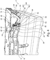
- Fig. 1 and 2 suggest a present coupling between the actuators 38 and the stacking brackets 18. This coupling according to the invention is based on the Fig. 3 and 4 in more detail.
- the leg 56 of the actuating element 38 also has on its outer side a rack portion 60 which is in engagement with a provided on the stacking bracket 18 / on the pivot arm 22 / on the bearing eye 36 of the pivot arm 22 gear portion 62.
- the rack portion 60 and the gear portion 62 together form a rack and pinion drive 64 (see FIG Figure 4 ).
- the actuator 38 is pressed by the coil spring 48 down and the resulting translational movement of the actuating element 38 is converted via the rack portion 60 in a rotational movement of the gear portion 62. Since the gear portion 62 is provided around the bearing eye 36 of the pivot arm 22 around, thereby directly a pivoting movement of the entire stacking bracket 18 is induced and thus the stacking bracket, as in Fig. 3 is shown biased in the stacking position.
- a stack edge support surface 14 on the short side walls 8 compared to the stack edge support surface 14 on the long side walls 6 is slightly offset down, so that the stacking bracket 18 is formed flush in the nest position with the stack edge support surface 14 of the long side walls 6.
- a container 2 If a container 2 is to be nested in a compatible container 2, first the stacking bracket 18 of the lower container 2 must be manually deflected into the nesting position.
- One or more locking elements (not shown) or latching element (s) can hold the stacking stirrups 18 of the container 2 in the nesting position and / or the actuating element 38 in an upper position.
- the actuators 38 of the upper container 2 are upwards Pressed down and the Nestrandetzlage character 16 of the upper container 2 comes into abutment with the Stapelrandauflage constitutional 14 of the lower container 2.
- the upward pressing of the actuators 38 takes place against the spring force of the four coil springs 48.
- the linear, translational upward movement of the actuators 38 results in that the rack sections 60 of the actuators 38 and the gear portions 62 of the stacking bracket 18, this translational movement is converted into a rotational movement of the stacking bracket 18 and thereby the stacking bails 18 are moved from the stacking position to the nesting position. If two containers 2 are nested in one another, all the following containers 2 can thus be nested on them without manual deflection of the stacking clips 18 being necessary.
- FIG. 5 a side view of a stacking bracket of the container in the stacking position
- Fig. 6 a side view of a stacking bracket of the container shown in the nest position.
- the rack portion 60 of the operating member 38 is engaged with the gear portion 62 of the stacking bracket 18 so that the operating member 38 can not fall downwardly due to gravity.
- the formation of the double T-shaped guide structure 40 and the double U-shaped portion 50 of the actuating element 38 go out of the FIGS. 5 and 6 even clearer.
- the individual components or the design and construction of the individual components of the container 2 must be precisely coordinated with each other.
- the edge of the beach / stacking edge 12, the stacking bracket 18 and the actuating element 38 must be suitably matched to one another. The same applies to the weight of the container 2 and the spring force of the coil springs 48th
- a second embodiment of a container 2 'according to the invention is shown.
- the container 2 'of the second embodiment differs from the container 2 of the first embodiment in particular in that not four actuators 38, but only two actuators 38' are provided.
- the special feature of the second embodiment is that both actuators 38 'with two stacking brackets 18 are engaged.
- a bow-shaped (as a bracket) and elongated actuator 38 'of the second embodiment extends completely in an area between the two stacking brackets 18 and has two end rack sections 60 (at the two end portions of the elongated bracket), one of which with a gear portion 62nd the first stacking bracket 18 and one with a gear portion 62 of the second stacking bracket 18 is engaged.
- a central translational actuation / movement of the actuators 38 ' both a rotational movement of the first stacking bracket 18 and a rotational movement of the second stacking bracket 18 are induced.
- a central portion 68 of the actuating element 38 ' is ergonomically / wavy shaped as a handle portion.
- a user in the second embodiment if he wants to manually move the stacking bails 18 from the stacking position to the nesting position, must operate only two actuators 38 '(and thus not four as in the first embodiment). Alternatively, of course, he can deflect the stacking bracket 18 manually again.
- An operation for a user is basically simplified by the second embodiment.
- coil springs 48 are provided for biasing the actuator 38 into a lower position, or for biasing the stacking stirrups 18 into the stacking position. Both coil springs 48 are provided between (and spaced from) the outer / end rack section 62 and the central section 68 of the actuator 38 ', respectively.
- the coil springs 48 are preferably arranged axially symmetrical to a center of the long side wall 6 and thus equally spaced from a side center.
- the coil springs 48 are disposed between a double T-shaped guide structure 40 provided in the sea beach 12 and a double U-shaped section 50 provided on the operating element 38 '.
- a plurality of further guide structures 70 are provided for guiding the actuating element 38 on the edge of the beach.
- the guide structures 70 are formed on the one hand by vertical ribs, which are formed on an inner wall 72 of the Nestrands 12, and on the other by portions of an outer wall 74 of the Nestrands 12. Characterized in that the actuating elements 38 are guided on both the inner wall 72 and on the outer wall 74 and extend in sections along the inner wall 72 and the outer wall 74 (actuator 38 'with mutually offset in a Nestrandtiefencardi sections), is a suitable Attachment / lateral fixation of the actuators 38 'in the beach 12 reaches. The gear portions 62 of the stacking bracket 18 again prevent falling down.
- actuation of the actuating element 38 takes place in the second Embodiment centered, so that overall a more uniform operation is achieved.
- One or more latching element (s) or latching element (s), not shown, can latch / lock the actuators 38 in an upper position and thus the stacking stirrups 18 in the nesting position.
Landscapes
- Engineering & Computer Science (AREA)
- Mechanical Engineering (AREA)
- Stackable Containers (AREA)
Priority Applications (4)
| Application Number | Priority Date | Filing Date | Title |
|---|---|---|---|
| ES17157009T ES2735412T3 (es) | 2017-02-20 | 2017-02-20 | Recipiente apilable y encajable |
| PL17157009T PL3363748T3 (pl) | 2017-02-20 | 2017-02-20 | Pojemnik dający się układać w stos jeden w drugim |
| EP17157009.6A EP3363748B1 (fr) | 2017-02-20 | 2017-02-20 | Récipient empilable et emboitable |
| PCT/EP2018/050586 WO2018149561A1 (fr) | 2017-02-20 | 2018-01-10 | Conteneur empilable et emboîtable |
Applications Claiming Priority (1)
| Application Number | Priority Date | Filing Date | Title |
|---|---|---|---|
| EP17157009.6A EP3363748B1 (fr) | 2017-02-20 | 2017-02-20 | Récipient empilable et emboitable |
Publications (2)
| Publication Number | Publication Date |
|---|---|
| EP3363748A1 true EP3363748A1 (fr) | 2018-08-22 |
| EP3363748B1 EP3363748B1 (fr) | 2019-05-22 |
Family
ID=58098532
Family Applications (1)
| Application Number | Title | Priority Date | Filing Date |
|---|---|---|---|
| EP17157009.6A Active EP3363748B1 (fr) | 2017-02-20 | 2017-02-20 | Récipient empilable et emboitable |
Country Status (4)
| Country | Link |
|---|---|
| EP (1) | EP3363748B1 (fr) |
| ES (1) | ES2735412T3 (fr) |
| PL (1) | PL3363748T3 (fr) |
| WO (1) | WO2018149561A1 (fr) |
Cited By (1)
| Publication number | Priority date | Publication date | Assignee | Title |
|---|---|---|---|---|
| GB2592104A (en) * | 2019-12-11 | 2021-08-18 | Loadhog Ltd | Container |
Citations (11)
| Publication number | Priority date | Publication date | Assignee | Title |
|---|---|---|---|---|
| US4241831A (en) * | 1977-06-03 | 1980-12-30 | Gianbattista Locatelli | Handle particularly for wire baskets |
| CA1128878A (fr) * | 1980-04-24 | 1982-08-03 | Phillips-Parkway Corporation | Plateau a pain tri-etage |
| US4643310A (en) * | 1984-09-20 | 1987-02-17 | Buckhorn Material Handling Group, Inc. | One hundred eighty degree stack and nest bakery tray with bails |
| EP0802119A2 (fr) | 1996-03-22 | 1997-10-22 | McKechnie UK Limited | Conteneur avec cloison amovible |
| EP0918694A1 (fr) | 1996-07-03 | 1999-06-02 | C G Paxton Limited | Conteneur |
| GB2350350A (en) * | 1999-05-08 | 2000-11-29 | Mckechnie Components Ltd | Stackable/nestable containers |
| EP1105256A1 (fr) * | 1998-08-15 | 2001-06-13 | Rotapak Limited | Manutention de contenants |
| EP1357045A1 (fr) * | 2002-03-15 | 2003-10-29 | Didak Injection N.V. | Récipient emboítable et empilable |
| US20070125779A1 (en) | 2005-11-02 | 2007-06-07 | Cope Andrew C | Collapsible container |
| US20090289059A1 (en) | 2006-11-22 | 2009-11-26 | Sergio Tontarelli | Box with collapsible walls designed to stack a corresponding box with lower dimensions |
| US20100133266A1 (en) | 2008-12-02 | 2010-06-03 | Cook Alan J | Container with retractable supports |
-
2017
- 2017-02-20 ES ES17157009T patent/ES2735412T3/es active Active
- 2017-02-20 EP EP17157009.6A patent/EP3363748B1/fr active Active
- 2017-02-20 PL PL17157009T patent/PL3363748T3/pl unknown
-
2018
- 2018-01-10 WO PCT/EP2018/050586 patent/WO2018149561A1/fr not_active Ceased
Patent Citations (11)
| Publication number | Priority date | Publication date | Assignee | Title |
|---|---|---|---|---|
| US4241831A (en) * | 1977-06-03 | 1980-12-30 | Gianbattista Locatelli | Handle particularly for wire baskets |
| CA1128878A (fr) * | 1980-04-24 | 1982-08-03 | Phillips-Parkway Corporation | Plateau a pain tri-etage |
| US4643310A (en) * | 1984-09-20 | 1987-02-17 | Buckhorn Material Handling Group, Inc. | One hundred eighty degree stack and nest bakery tray with bails |
| EP0802119A2 (fr) | 1996-03-22 | 1997-10-22 | McKechnie UK Limited | Conteneur avec cloison amovible |
| EP0918694A1 (fr) | 1996-07-03 | 1999-06-02 | C G Paxton Limited | Conteneur |
| EP1105256A1 (fr) * | 1998-08-15 | 2001-06-13 | Rotapak Limited | Manutention de contenants |
| GB2350350A (en) * | 1999-05-08 | 2000-11-29 | Mckechnie Components Ltd | Stackable/nestable containers |
| EP1357045A1 (fr) * | 2002-03-15 | 2003-10-29 | Didak Injection N.V. | Récipient emboítable et empilable |
| US20070125779A1 (en) | 2005-11-02 | 2007-06-07 | Cope Andrew C | Collapsible container |
| US20090289059A1 (en) | 2006-11-22 | 2009-11-26 | Sergio Tontarelli | Box with collapsible walls designed to stack a corresponding box with lower dimensions |
| US20100133266A1 (en) | 2008-12-02 | 2010-06-03 | Cook Alan J | Container with retractable supports |
Cited By (2)
| Publication number | Priority date | Publication date | Assignee | Title |
|---|---|---|---|---|
| GB2592104A (en) * | 2019-12-11 | 2021-08-18 | Loadhog Ltd | Container |
| GB2592104B (en) * | 2019-12-11 | 2023-06-07 | Loadhog Ltd | Container |
Also Published As
| Publication number | Publication date |
|---|---|
| WO2018149561A1 (fr) | 2018-08-23 |
| EP3363748B1 (fr) | 2019-05-22 |
| PL3363748T3 (pl) | 2019-10-31 |
| ES2735412T3 (es) | 2019-12-18 |
Similar Documents
| Publication | Publication Date | Title |
|---|---|---|
| EP2982624B1 (fr) | Dispositif de retenue et système de stockage pour empilement de récipients | |
| EP1754897B1 (fr) | Dispositif de stockage | |
| EP0786412B1 (fr) | Récipient de stockage ou de transport | |
| DE102013004590B4 (de) | Kasten aus Kunststoff, insbesondere Flaschenkasten | |
| DE10041886A1 (de) | Transportbehälter | |
| DE202009018780U1 (de) | Großcontainer | |
| DE102018106981A1 (de) | Behältersystem mit Rahmenelement | |
| EP3587294B1 (fr) | Récipient empilable pourvu de mécanisme de raccordement | |
| DE102019111950B4 (de) | Stapelbare Lagereinheit und Stapel aus Lagereinheiten | |
| DE202015106824U1 (de) | Transportbox | |
| EP3375725B1 (fr) | Dispositif d'empilement pour palettes | |
| EP2112080B1 (fr) | Récipient de transport et de stockage doté d'un organe de verrouillage | |
| EP2840034B1 (fr) | Dispositif de verrouillage et de déverrouillage des parois latérales rabattables ou pliables d'un récipient | |
| DE102014104117A1 (de) | Regal-Behälter-System | |
| EP3363748B1 (fr) | Récipient empilable et emboitable | |
| DE102015121865B4 (de) | Transportbox | |
| EP1824747B1 (fr) | Conteneur de transport et de stockage repliable | |
| EP3381825A1 (fr) | Boîte ayant des parois latérales pliables et un mécanisme de verrouillage sur le bord | |
| EP3034425B1 (fr) | Recipient emboitable dote de parois laterales basculantes | |
| EP3107815A1 (fr) | Support emboîtable pour conteneur de transport | |
| EP2767483A2 (fr) | Récipient de transport empilable | |
| DE202004014340U1 (de) | Drehstapelbehälter | |
| DE29819420U1 (de) | Tablar o.dgl. Tragmittel | |
| EP3162725B1 (fr) | Recipient empilable et emboitable | |
| EP3642126B1 (fr) | Système de rails, caisse de transport pourvue d'au moins un tel système de rails, ainsi que procédé et utilisation |
Legal Events
| Date | Code | Title | Description |
|---|---|---|---|
| PUAI | Public reference made under article 153(3) epc to a published international application that has entered the european phase |
Free format text: ORIGINAL CODE: 0009012 |
|
| STAA | Information on the status of an ep patent application or granted ep patent |
Free format text: STATUS: THE APPLICATION HAS BEEN PUBLISHED |
|
| AK | Designated contracting states |
Kind code of ref document: A1 Designated state(s): AL AT BE BG CH CY CZ DE DK EE ES FI FR GB GR HR HU IE IS IT LI LT LU LV MC MK MT NL NO PL PT RO RS SE SI SK SM TR |
|
| AX | Request for extension of the european patent |
Extension state: BA ME |
|
| STAA | Information on the status of an ep patent application or granted ep patent |
Free format text: STATUS: REQUEST FOR EXAMINATION WAS MADE |
|
| 17P | Request for examination filed |
Effective date: 20181001 |
|
| RBV | Designated contracting states (corrected) |
Designated state(s): AL AT BE BG CH CY CZ DE DK EE ES FI FR GB GR HR HU IE IS IT LI LT LU LV MC MK MT NL NO PL PT RO RS SE SI SK SM TR |
|
| GRAP | Despatch of communication of intention to grant a patent |
Free format text: ORIGINAL CODE: EPIDOSNIGR1 |
|
| STAA | Information on the status of an ep patent application or granted ep patent |
Free format text: STATUS: GRANT OF PATENT IS INTENDED |
|
| INTG | Intention to grant announced |
Effective date: 20181128 |
|
| GRAS | Grant fee paid |
Free format text: ORIGINAL CODE: EPIDOSNIGR3 |
|
| GRAA | (expected) grant |
Free format text: ORIGINAL CODE: 0009210 |
|
| STAA | Information on the status of an ep patent application or granted ep patent |
Free format text: STATUS: THE PATENT HAS BEEN GRANTED |
|
| RAP1 | Party data changed (applicant data changed or rights of an application transferred) |
Owner name: SCHOELLER ALLIBERT GMBH |
|
| RIN1 | Information on inventor provided before grant (corrected) |
Inventor name: HUIZINGH, JOHN |
|
| AK | Designated contracting states |
Kind code of ref document: B1 Designated state(s): AL AT BE BG CH CY CZ DE DK EE ES FI FR GB GR HR HU IE IS IT LI LT LU LV MC MK MT NL NO PL PT RO RS SE SI SK SM TR |
|
| REG | Reference to a national code |
Ref country code: GB Ref legal event code: FG4D Free format text: NOT ENGLISH |
|
| REG | Reference to a national code |
Ref country code: CH Ref legal event code: EP |
|
| REG | Reference to a national code |
Ref country code: IE Ref legal event code: FG4D Free format text: LANGUAGE OF EP DOCUMENT: GERMAN |
|
| REG | Reference to a national code |
Ref country code: DE Ref legal event code: R096 Ref document number: 502017001365 Country of ref document: DE |
|
| REG | Reference to a national code |
Ref country code: AT Ref legal event code: REF Ref document number: 1135827 Country of ref document: AT Kind code of ref document: T Effective date: 20190615 |
|
| REG | Reference to a national code |
Ref country code: NL Ref legal event code: FP |
|
| REG | Reference to a national code |
Ref country code: SE Ref legal event code: TRGR |
|
| REG | Reference to a national code |
Ref country code: NO Ref legal event code: T2 Effective date: 20190522 |
|
| REG | Reference to a national code |
Ref country code: LT Ref legal event code: MG4D |
|
| PG25 | Lapsed in a contracting state [announced via postgrant information from national office to epo] |
Ref country code: AL Free format text: LAPSE BECAUSE OF FAILURE TO SUBMIT A TRANSLATION OF THE DESCRIPTION OR TO PAY THE FEE WITHIN THE PRESCRIBED TIME-LIMIT Effective date: 20190522 Ref country code: PT Free format text: LAPSE BECAUSE OF FAILURE TO SUBMIT A TRANSLATION OF THE DESCRIPTION OR TO PAY THE FEE WITHIN THE PRESCRIBED TIME-LIMIT Effective date: 20190922 Ref country code: LT Free format text: LAPSE BECAUSE OF FAILURE TO SUBMIT A TRANSLATION OF THE DESCRIPTION OR TO PAY THE FEE WITHIN THE PRESCRIBED TIME-LIMIT Effective date: 20190522 Ref country code: HR Free format text: LAPSE BECAUSE OF FAILURE TO SUBMIT A TRANSLATION OF THE DESCRIPTION OR TO PAY THE FEE WITHIN THE PRESCRIBED TIME-LIMIT Effective date: 20190522 Ref country code: FI Free format text: LAPSE BECAUSE OF FAILURE TO SUBMIT A TRANSLATION OF THE DESCRIPTION OR TO PAY THE FEE WITHIN THE PRESCRIBED TIME-LIMIT Effective date: 20190522 |
|
| PG25 | Lapsed in a contracting state [announced via postgrant information from national office to epo] |
Ref country code: GR Free format text: LAPSE BECAUSE OF FAILURE TO SUBMIT A TRANSLATION OF THE DESCRIPTION OR TO PAY THE FEE WITHIN THE PRESCRIBED TIME-LIMIT Effective date: 20190823 Ref country code: RS Free format text: LAPSE BECAUSE OF FAILURE TO SUBMIT A TRANSLATION OF THE DESCRIPTION OR TO PAY THE FEE WITHIN THE PRESCRIBED TIME-LIMIT Effective date: 20190522 Ref country code: LV Free format text: LAPSE BECAUSE OF FAILURE TO SUBMIT A TRANSLATION OF THE DESCRIPTION OR TO PAY THE FEE WITHIN THE PRESCRIBED TIME-LIMIT Effective date: 20190522 Ref country code: BG Free format text: LAPSE BECAUSE OF FAILURE TO SUBMIT A TRANSLATION OF THE DESCRIPTION OR TO PAY THE FEE WITHIN THE PRESCRIBED TIME-LIMIT Effective date: 20190822 |
|
| REG | Reference to a national code |
Ref country code: ES Ref legal event code: FG2A Ref document number: 2735412 Country of ref document: ES Kind code of ref document: T3 Effective date: 20191218 |
|
| PG25 | Lapsed in a contracting state [announced via postgrant information from national office to epo] |
Ref country code: RO Free format text: LAPSE BECAUSE OF FAILURE TO SUBMIT A TRANSLATION OF THE DESCRIPTION OR TO PAY THE FEE WITHIN THE PRESCRIBED TIME-LIMIT Effective date: 20190522 Ref country code: CZ Free format text: LAPSE BECAUSE OF FAILURE TO SUBMIT A TRANSLATION OF THE DESCRIPTION OR TO PAY THE FEE WITHIN THE PRESCRIBED TIME-LIMIT Effective date: 20190522 Ref country code: EE Free format text: LAPSE BECAUSE OF FAILURE TO SUBMIT A TRANSLATION OF THE DESCRIPTION OR TO PAY THE FEE WITHIN THE PRESCRIBED TIME-LIMIT Effective date: 20190522 Ref country code: DK Free format text: LAPSE BECAUSE OF FAILURE TO SUBMIT A TRANSLATION OF THE DESCRIPTION OR TO PAY THE FEE WITHIN THE PRESCRIBED TIME-LIMIT Effective date: 20190522 Ref country code: SK Free format text: LAPSE BECAUSE OF FAILURE TO SUBMIT A TRANSLATION OF THE DESCRIPTION OR TO PAY THE FEE WITHIN THE PRESCRIBED TIME-LIMIT Effective date: 20190522 |
|
| REG | Reference to a national code |
Ref country code: DE Ref legal event code: R097 Ref document number: 502017001365 Country of ref document: DE |
|
| PG25 | Lapsed in a contracting state [announced via postgrant information from national office to epo] |
Ref country code: SM Free format text: LAPSE BECAUSE OF FAILURE TO SUBMIT A TRANSLATION OF THE DESCRIPTION OR TO PAY THE FEE WITHIN THE PRESCRIBED TIME-LIMIT Effective date: 20190522 |
|
| PLBE | No opposition filed within time limit |
Free format text: ORIGINAL CODE: 0009261 |
|
| STAA | Information on the status of an ep patent application or granted ep patent |
Free format text: STATUS: NO OPPOSITION FILED WITHIN TIME LIMIT |
|
| PG25 | Lapsed in a contracting state [announced via postgrant information from national office to epo] |
Ref country code: TR Free format text: LAPSE BECAUSE OF FAILURE TO SUBMIT A TRANSLATION OF THE DESCRIPTION OR TO PAY THE FEE WITHIN THE PRESCRIBED TIME-LIMIT Effective date: 20190522 |
|
| 26N | No opposition filed |
Effective date: 20200225 |
|
| PGFP | Annual fee paid to national office [announced via postgrant information from national office to epo] |
Ref country code: ES Payment date: 20200320 Year of fee payment: 4 Ref country code: NL Payment date: 20200220 Year of fee payment: 4 Ref country code: NO Payment date: 20200220 Year of fee payment: 4 Ref country code: IT Payment date: 20200229 Year of fee payment: 4 Ref country code: PL Payment date: 20200219 Year of fee payment: 4 Ref country code: DE Payment date: 20200205 Year of fee payment: 4 Ref country code: SE Payment date: 20200224 Year of fee payment: 4 |
|
| PGFP | Annual fee paid to national office [announced via postgrant information from national office to epo] |
Ref country code: FR Payment date: 20200219 Year of fee payment: 4 |
|
| REG | Reference to a national code |
Ref country code: CH Ref legal event code: PL |
|
| REG | Reference to a national code |
Ref country code: BE Ref legal event code: MM Effective date: 20200229 |
|
| PG25 | Lapsed in a contracting state [announced via postgrant information from national office to epo] |
Ref country code: MC Free format text: LAPSE BECAUSE OF FAILURE TO SUBMIT A TRANSLATION OF THE DESCRIPTION OR TO PAY THE FEE WITHIN THE PRESCRIBED TIME-LIMIT Effective date: 20190522 Ref country code: LU Free format text: LAPSE BECAUSE OF NON-PAYMENT OF DUE FEES Effective date: 20200220 |
|
| PG25 | Lapsed in a contracting state [announced via postgrant information from national office to epo] |
Ref country code: LI Free format text: LAPSE BECAUSE OF NON-PAYMENT OF DUE FEES Effective date: 20200229 Ref country code: CH Free format text: LAPSE BECAUSE OF NON-PAYMENT OF DUE FEES Effective date: 20200229 |
|
| PG25 | Lapsed in a contracting state [announced via postgrant information from national office to epo] |
Ref country code: IE Free format text: LAPSE BECAUSE OF NON-PAYMENT OF DUE FEES Effective date: 20200220 |
|
| PG25 | Lapsed in a contracting state [announced via postgrant information from national office to epo] |
Ref country code: BE Free format text: LAPSE BECAUSE OF NON-PAYMENT OF DUE FEES Effective date: 20200229 |
|
| REG | Reference to a national code |
Ref country code: DE Ref legal event code: R119 Ref document number: 502017001365 Country of ref document: DE |
|
| REG | Reference to a national code |
Ref country code: NO Ref legal event code: MMEP |
|
| REG | Reference to a national code |
Ref country code: SE Ref legal event code: EUG |
|
| GBPC | Gb: european patent ceased through non-payment of renewal fee |
Effective date: 20210220 |
|
| PG25 | Lapsed in a contracting state [announced via postgrant information from national office to epo] |
Ref country code: NO Free format text: LAPSE BECAUSE OF NON-PAYMENT OF DUE FEES Effective date: 20210228 Ref country code: SE Free format text: LAPSE BECAUSE OF NON-PAYMENT OF DUE FEES Effective date: 20210221 |
|
| REG | Reference to a national code |
Ref country code: NL Ref legal event code: MM Effective date: 20210301 |
|
| PG25 | Lapsed in a contracting state [announced via postgrant information from national office to epo] |
Ref country code: NL Free format text: LAPSE BECAUSE OF NON-PAYMENT OF DUE FEES Effective date: 20210301 |
|
| PG25 | Lapsed in a contracting state [announced via postgrant information from national office to epo] |
Ref country code: DE Free format text: LAPSE BECAUSE OF NON-PAYMENT OF DUE FEES Effective date: 20210901 Ref country code: FR Free format text: LAPSE BECAUSE OF NON-PAYMENT OF DUE FEES Effective date: 20210228 Ref country code: GB Free format text: LAPSE BECAUSE OF NON-PAYMENT OF DUE FEES Effective date: 20210220 |
|
| PG25 | Lapsed in a contracting state [announced via postgrant information from national office to epo] |
Ref country code: IT Free format text: LAPSE BECAUSE OF NON-PAYMENT OF DUE FEES Effective date: 20210220 |
|
| REG | Reference to a national code |
Ref country code: ES Ref legal event code: FD2A Effective date: 20220504 |
|
| PG25 | Lapsed in a contracting state [announced via postgrant information from national office to epo] |
Ref country code: MT Free format text: LAPSE BECAUSE OF FAILURE TO SUBMIT A TRANSLATION OF THE DESCRIPTION OR TO PAY THE FEE WITHIN THE PRESCRIBED TIME-LIMIT Effective date: 20190522 Ref country code: CY Free format text: LAPSE BECAUSE OF FAILURE TO SUBMIT A TRANSLATION OF THE DESCRIPTION OR TO PAY THE FEE WITHIN THE PRESCRIBED TIME-LIMIT Effective date: 20190522 |
|
| PG25 | Lapsed in a contracting state [announced via postgrant information from national office to epo] |
Ref country code: MK Free format text: LAPSE BECAUSE OF FAILURE TO SUBMIT A TRANSLATION OF THE DESCRIPTION OR TO PAY THE FEE WITHIN THE PRESCRIBED TIME-LIMIT Effective date: 20190522 Ref country code: IS Free format text: LAPSE BECAUSE OF FAILURE TO SUBMIT A TRANSLATION OF THE DESCRIPTION OR TO PAY THE FEE WITHIN THE PRESCRIBED TIME-LIMIT Effective date: 20190922 |
|
| PG25 | Lapsed in a contracting state [announced via postgrant information from national office to epo] |
Ref country code: ES Free format text: LAPSE BECAUSE OF NON-PAYMENT OF DUE FEES Effective date: 20210221 |
|
| PG25 | Lapsed in a contracting state [announced via postgrant information from national office to epo] |
Ref country code: PL Free format text: LAPSE BECAUSE OF NON-PAYMENT OF DUE FEES Effective date: 20210220 |
|
| REG | Reference to a national code |
Ref country code: AT Ref legal event code: MM01 Ref document number: 1135827 Country of ref document: AT Kind code of ref document: T Effective date: 20220220 |
|
| PG25 | Lapsed in a contracting state [announced via postgrant information from national office to epo] |
Ref country code: AT Free format text: LAPSE BECAUSE OF NON-PAYMENT OF DUE FEES Effective date: 20220220 |
|
| PG25 | Lapsed in a contracting state [announced via postgrant information from national office to epo] |
Ref country code: SI Free format text: LAPSE BECAUSE OF FAILURE TO SUBMIT A TRANSLATION OF THE DESCRIPTION OR TO PAY THE FEE WITHIN THE PRESCRIBED TIME-LIMIT Effective date: 20190522 |