EP3363754A1 - Ensemble et procédé de balayage de bac - Google Patents
Ensemble et procédé de balayage de bac Download PDFInfo
- Publication number
- EP3363754A1 EP3363754A1 EP18157117.5A EP18157117A EP3363754A1 EP 3363754 A1 EP3363754 A1 EP 3363754A1 EP 18157117 A EP18157117 A EP 18157117A EP 3363754 A1 EP3363754 A1 EP 3363754A1
- Authority
- EP
- European Patent Office
- Prior art keywords
- brush
- wall
- sweep
- bin
- axis
- Prior art date
- Legal status (The legal status is an assumption and is not a legal conclusion. Google has not performed a legal analysis and makes no representation as to the accuracy of the status listed.)
- Withdrawn
Links
- 238000000034 method Methods 0.000 title claims description 11
- 239000000463 material Substances 0.000 claims abstract description 15
- 230000008878 coupling Effects 0.000 claims description 4
- 238000010168 coupling process Methods 0.000 claims description 4
- 238000005859 coupling reaction Methods 0.000 claims description 4
- 238000010276 construction Methods 0.000 description 8
- 239000008187 granular material Substances 0.000 description 4
- 230000005540 biological transmission Effects 0.000 description 2
- 230000035939 shock Effects 0.000 description 2
- 108010016634 Seed Storage Proteins Proteins 0.000 description 1
- 238000004140 cleaning Methods 0.000 description 1
- 230000008520 organization Effects 0.000 description 1
Images


Classifications
-
- B—PERFORMING OPERATIONS; TRANSPORTING
- B65—CONVEYING; PACKING; STORING; HANDLING THIN OR FILAMENTARY MATERIAL
- B65G—TRANSPORT OR STORAGE DEVICES, e.g. CONVEYORS FOR LOADING OR TIPPING, SHOP CONVEYOR SYSTEMS OR PNEUMATIC TUBE CONVEYORS
- B65G65/00—Loading or unloading
- B65G65/30—Methods or devices for filling or emptying bunkers, hoppers, tanks, or like containers, of interest apart from their use in particular chemical or physical processes or their application in particular machines, e.g. not covered by a single other subclass
- B65G65/34—Emptying devices
- B65G65/40—Devices for emptying otherwise than from the top
- B65G65/48—Devices for emptying otherwise than from the top using other rotating means, e.g. rotating pressure sluices in pneumatic systems
- B65G65/4809—Devices for emptying otherwise than from the top using other rotating means, e.g. rotating pressure sluices in pneumatic systems rotating about a substantially vertical axis
- B65G65/4836—Devices for emptying otherwise than from the top using other rotating means, e.g. rotating pressure sluices in pneumatic systems rotating about a substantially vertical axis and moving material over a stationary surface, e.g. sweep arms or wheels
- B65G65/4854—Devices for emptying otherwise than from the top using other rotating means, e.g. rotating pressure sluices in pneumatic systems rotating about a substantially vertical axis and moving material over a stationary surface, e.g. sweep arms or wheels mounted on a carriage, e.g. for movement along slit-like outlets
-
- B—PERFORMING OPERATIONS; TRANSPORTING
- B65—CONVEYING; PACKING; STORING; HANDLING THIN OR FILAMENTARY MATERIAL
- B65G—TRANSPORT OR STORAGE DEVICES, e.g. CONVEYORS FOR LOADING OR TIPPING, SHOP CONVEYOR SYSTEMS OR PNEUMATIC TUBE CONVEYORS
- B65G65/00—Loading or unloading
- B65G65/30—Methods or devices for filling or emptying bunkers, hoppers, tanks, or like containers, of interest apart from their use in particular chemical or physical processes or their application in particular machines, e.g. not covered by a single other subclass
- B65G65/34—Emptying devices
- B65G65/40—Devices for emptying otherwise than from the top
- B65G65/46—Devices for emptying otherwise than from the top using screw conveyors
- B65G65/466—Devices for emptying otherwise than from the top using screw conveyors arranged to be movable
-
- B—PERFORMING OPERATIONS; TRANSPORTING
- B65—CONVEYING; PACKING; STORING; HANDLING THIN OR FILAMENTARY MATERIAL
- B65G—TRANSPORT OR STORAGE DEVICES, e.g. CONVEYORS FOR LOADING OR TIPPING, SHOP CONVEYOR SYSTEMS OR PNEUMATIC TUBE CONVEYORS
- B65G69/00—Auxiliary measures taken, or devices used, in connection with loading or unloading
- B65G69/08—Devices for emptying storage spaces as completely as possible
Definitions
- the present invention relates to an improved bin sweep, and more particularly to a bin sweep incorporating a brush to remove materials from a position adjacent the walls of the bin.
- a need may exist for a bin sweep that can remove grain from a position adjacent the bin wall.
- the present invention relates to a rotary brush sweep attachment allowing for a safer, more efficient clean out process by removing nearly all the grain away from adjacent the bin wall to where the sweep auger can get to it.
- One embodiment of the invention relates to a bin sweep system having a sweep auger and a brush, wherein the brush extends radially beyond the end of the sweep auger to contact the bin wall during operation of the bin sweep to sweep material away from the wall.
- the sweep auger rotates about a first axis and the brush rotates about a second axis.
- the first axis can be generally parallel to the bin floor while the second axis can be generally parallel to the bin wall.
- the sweep system includes a cycloidal drive to power a wheel from the sweep auger.
- a flexible drive shaft extends between a distal end of the sweep auger and the brush to rotationally drive the brush about the second axis.
- One independent aspect of the present invention is that the rotary brush can be installed and uninstalled without removal of other bin components.
- the rotary brush is bias loaded to float with the bin wall.
- the biasing element such as a spring, ensures the brush stays in contact with bin wall even as the distance between the end of the sweep and wall is constantly changing.
- the rotary brush can include a guide wheel ensuring minimal pressure is applied on the bin wall, minimizing wear and force on the wall and bolting hardware.
- a method of using a bin sweep to remove material from a bin having a floor and a wall includes providing a sweep auger having a first end and a second end radially displaced from the first end, the sweep auger positioned within the bin for rotation about a first axis substantially parallel to the floor; providing a brush coupled to the second end of the sweep auger for rotation about a second axis substantially parallel to the wall; operating the sweep auger about the first axis to cause movement of the material towards an opening in the bin floor; and operating the brush about the second axis to move material located adjacent the wall to a position which the sweep auger can reach.
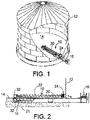
- a bin sweep 10 is generally used in a circular bin or storage container 12 having a substantially flat bin floor 14.
- the bin sweep 10 can be pivotally mounted near the center of the bin 12 so that it can sweep grain, seed, or other material toward an outlet 16 that is located proximate the center of the bin 12.
- a bin sweep 10 generally includes an engine or motor 18, an auger 20 having a first end and a second end, and a cover or housing 22 that at least partially encloses the auger 20.
- the bin sweep 10 also includes a wheel 24.
- the wheel 24 is coupled to the sweep auger 20 and disposed proximate an outer distal end of the sweep auger 20 for supporting the sweep auger 20 and driving the sweep auger 20 around the floor 14 storage container 12.
- the sweep auger 20 and the wheel 24 are disposed inside the storage container 12.
- the wheel 24 can be constructed many different ways. For example, it can be fairly conventional in construction. Alternatively, in some embodiments, it can be cycloidal wheel drive such as described in US2016/0200528 , the teachings of which are hereby incorporated by reference in their entirety.
- the motor 18 drives the unload auger 21 for rotation, which is drivingly coupled to the sweep auger 20 through drive boxes 32 to drive the sweep auger 20 for rotation, which is drivingly coupled to the input shaft of the wheel 24.
- the input shaft and the sweep auger 20 are both coupled concentrically with the wheel 24, e.g., coaxially with the axis of rotation of the wheel 24.
- the wheel 24 moves the sweep auger 20 around the storage container 12, as described above.
- various combinations of separate motors may be employed to drive the unload auger 21, the sweep auger 20, and the wheel 24.
- a separate motor may be dedicated to each of the unload auger 21, the sweep auger 20, and the wheel 24.
- various combinations of one or more motors may be employed to drive the unload auger 21, the sweep auger 20, and the wheel 24 in various combinations and configurations.
- the motor 18 is disposed outside of the storage bin 12 proximate the external granule discharge. In other constructions, the motor 18 (or some or all of the motors) may be disposed inside the storage container 12.
- a brush 38 is coupled to bin sweep 10. As noted above, the wheel 24 cannot abut the wall 12. As such, material is left between the wheel 24 and the wall 12. The brush 38 is provided to move the material from this region to a location in which the sweep auger 20 can reach the material.
- the brush 38 can be comprised of a plurality of bristles.
- the bristles may be long, short, stiff, soft, wide, narrow, and any combination thereof.
- Soft bristles can be used when the bin sweep 10 is used in conjunction with a seed storage bin, as the soft bristles are gentle on the seeds and thus prevent damaging the seeds.
- the bristles 38 can be substantially in contact with the bin wall 12 and floor 14. This can be accomplished through a biasing element, such as a spring, shock or other biasing means.
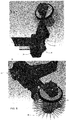
- the brush 38 can be oriented many different ways to clear material from the interface of the bin wall 12 and the bin floor 14. However, as illustrated, in preferred embodiments, the brush is oriented to rotate about an axis generally parallel with the bin wall 12. This allows for maximum contact between the brush 38 and floor/wall interface, due to the generally cylindrical configuration of the brush 38. In other brush configurations, a non-parallel orientation may provide the best contact between the brush and floor/wall interface.
- the brush is coupled to the end of the sweep auger 20. More particularly, the brush 38 is coupled to the wheel 24.
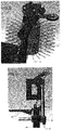
- the brush 38 can be driven many different ways. For example, it can be driven by a chain or a belt drive, which may include pulleys and/or sprockets to vary the speed of the bin sweep 10 during operation. Also, the brush 38 can include a separate motor or engine to drive the brush 38. Additionally, as shown in FIGS 3-10 , a flexible drive shaft, such as taught in US Published Application No. 2015/0342113 and US Patent No. 9,366,297 , can be used to drive the brush 38. The teachings of US Published Application No. 2015/0342113 and US Patent No. 9,366,297 are hereby incorporated by reference in their entirety.
- the illustrated brush 38 is driven by a flexible shaft drive system 40 having a first gearbox or transmission 42 driven by the motor 18 through the sweep auger 20 and/or wheel 24.
- This gearbox drives a flexible drive shaft 44, which in turn drives a second gearbox or transmission 46.
- the second gearbox 46 drives the brush 38.
- the first gearbox 42 can be driven several different ways. In one embodiment, it is driven by the shaft of the sweep auger 20. In another embodiment, it is driven by the wheel 24. Depending upon which structures the gearbox 42 attaches to, appropriate gearing can be provided in the first or second gearbox 42, 46 to rotate the brush 38 at a predetermined, desired speed.
- the brush 38 and second gearbox 46 are coupled to a frame 50, which is coupled to the housing 22 of the sweep auger 20.
- the frame 50 can be constructed and oriented many different ways known in the art.
- the frame 50 has a mounting portion 52 for connecting the frame to the housing 22.
- the frame 50 also has top arm 54 and a bottom arm 56 for supporting the top and bottom of the brush 38.
- the second gearbox can be mounted to the top arm 54 to drive the brush 38.
- the frame 50 can include a hinged portion 58 to allow the brush 38 to pivot towards the bin wall 12.
- the hinged portion 58 can be located adjacent mounting portion 52, allowing the top arm 54 and bottom arm 56 to pivot about an axis that is substantially parallel to the bin wall 12.
- some embodiments also include a biasing element 70 to bias the brush into engagement with the bin wall 12.
- the biasing element 70 ensures the brush stays in contact with bin wall even as the distance between the end of the sweep and wall is constantly changing.
- the biasing element can include a spring, a shock or other known biasing means. As shown in FIGS 3-10 , the biasing element 70 can extend between the frame 50 mounting portion 52 and another portion of the frame 50 on the hinged portion 58.
- some embodiments of the bin sweep 10 can also include a guide wheel 80.
- the guide wheel 80 can be provided to ensure excessive pressure is not applied on the bin wall 12; thus, minimizing wear and force on the wall 12, bolting hardware or other structural elements of the bin.
- the guide wheel 80 can be configured many different ways.
- FIGS 7-8 provide a first embodiment wherein the guide wheel 80 is concentric with the brush 38.
- the guide wheel 80 having a diameter less than the diameter of the brush 38.
- FIGS 9-10 provide second embodiment wherein the guide wheel 80 is mounted to a support arm 82 and having an axis of rotation that is offset with respect to the brush 38.
- the brush 38 of this embodiment extends further radially towards the bin wall 12 than the guide wheel to ensure sufficient contact between the brush 38 and wall 12 even with some wear on the brush 38.
- the motor 18 drives the wheel 24 and sweep auger 20 to move the granules towards the discharge opening 16 proximate the center of the storage container 12.
- the motor 18 also drives the unload auger 21 to move the granules towards the external granule discharge outside of the storage container 12.
- the motor 18 also drives the wheel 24 to move slowly about a circumference of the storage container 12 to move the sweep auger 20 slowly around the discharge opening as the sweep auger 20 rotates about its own axis which is generally parallel to the floor.
- the brush 38 is driven about an axis that generally parallel to the bin wall 12.
- the brush 38 is driven by the drive system 40, which ultimately receives power from the motor 18 in one of the ways discussed above. Rotation of the brush 38 moves material located between the end of the auger 20 (or wheel 24 - depending upon the construction of the wheel) and the wall 12 to within reach of the auger 20 (or wheel 24). As this distance changes, the biasing element 70 and/or guide wheel 80 can maintain appropriate contact between the brush 38 and the wall 12.
- the cycloidal drive reduces the speed of the input shaft such that the wheel 24 is driven at a lower speed than the input shaft.
- the wheel 24 is driven slowly relative to the input shaft and in the same direction as the input shaft to move the sweep auger 20 around the storage container 12.
Landscapes
- Engineering & Computer Science (AREA)
- Mechanical Engineering (AREA)
- Filling Or Emptying Of Bunkers, Hoppers, And Tanks (AREA)
- Brushes (AREA)
- Earth Drilling (AREA)
Applications Claiming Priority (1)
| Application Number | Priority Date | Filing Date | Title |
|---|---|---|---|
| US201762460361P | 2017-02-17 | 2017-02-17 |
Publications (1)
| Publication Number | Publication Date |
|---|---|
| EP3363754A1 true EP3363754A1 (fr) | 2018-08-22 |
Family
ID=61231116
Family Applications (1)
| Application Number | Title | Priority Date | Filing Date |
|---|---|---|---|
| EP18157117.5A Withdrawn EP3363754A1 (fr) | 2017-02-17 | 2018-02-16 | Ensemble et procédé de balayage de bac |
Country Status (4)
| Country | Link |
|---|---|
| US (1) | US20180237236A1 (fr) |
| EP (1) | EP3363754A1 (fr) |
| BR (1) | BR102018003035A2 (fr) |
| CA (1) | CA2995442A1 (fr) |
Families Citing this family (7)
| Publication number | Priority date | Publication date | Assignee | Title |
|---|---|---|---|---|
| US10654668B2 (en) | 2017-02-01 | 2020-05-19 | Sukup Manufacturing Co. | Sweep auger drive shield with gravity reclaim |
| US11618639B1 (en) | 2019-03-08 | 2023-04-04 | Sioux Steel Company | Storage bin sweep system with enhanced peripheral sweep capability |
| US11299358B1 (en) | 2019-03-08 | 2022-04-12 | Sioux Steel Company | Storage bin sweep system with enhanced peripheral sweep capability |
| US12275604B2 (en) | 2019-08-20 | 2025-04-15 | Sukup Manufacturing Co. | Sweep system for full elevated floor grain bins |
| WO2023059715A1 (fr) * | 2021-10-07 | 2023-04-13 | Sukup Manufacturing Co. | Système de balayage entraîné par courroie pour cellules à grains |
| US12473158B2 (en) | 2022-06-01 | 2025-11-18 | Sukup Manufacturing Co. | Sweep system for grain bins |
| CN115626497B (zh) * | 2022-11-11 | 2024-07-26 | 北新建材(陕西)有限公司 | 一种防蓬料淀粉添加装置及方法 |
Citations (8)
| Publication number | Priority date | Publication date | Assignee | Title |
|---|---|---|---|---|
| BE662553A (fr) * | 1964-04-15 | 1965-08-02 | ||
| JPS59141751U (ja) * | 1983-03-10 | 1984-09-21 | オリオン機械株式会社 | サイロ内壁清掃ブラシ付牧草取り出し装置 |
| JPS61217438A (ja) * | 1985-03-22 | 1986-09-27 | Hitachi Ltd | サイロ |
| SU1676505A1 (ru) * | 1989-06-26 | 1991-09-15 | Украинский научно-исследовательский институт механизации и электрификации сельского хозяйства | Устройство дл разгрузки башенных хранилищ кормов |
| JP3463773B2 (ja) * | 1994-12-20 | 2003-11-05 | セイレイ工業株式会社 | ライスキャビン内の穀粒排出装置 |
| US20140057728A1 (en) * | 2011-04-14 | 2014-02-27 | Actuant Corporaton | Seed metering device drive system |
| US20150342113A1 (en) | 2012-09-11 | 2015-12-03 | Actuant Corporation | Reversible seeder transmission and seeder drive apparatus |
| US20160200528A1 (en) | 2013-08-13 | 2016-07-14 | Actuant Corporation | Cycloidal wheel drive |
-
2018
- 2018-02-16 EP EP18157117.5A patent/EP3363754A1/fr not_active Withdrawn
- 2018-02-16 CA CA2995442A patent/CA2995442A1/fr active Pending
- 2018-02-16 BR BR102018003035-3A patent/BR102018003035A2/pt not_active Application Discontinuation
- 2018-02-19 US US15/898,932 patent/US20180237236A1/en not_active Abandoned
Patent Citations (9)
| Publication number | Priority date | Publication date | Assignee | Title |
|---|---|---|---|---|
| BE662553A (fr) * | 1964-04-15 | 1965-08-02 | ||
| JPS59141751U (ja) * | 1983-03-10 | 1984-09-21 | オリオン機械株式会社 | サイロ内壁清掃ブラシ付牧草取り出し装置 |
| JPS61217438A (ja) * | 1985-03-22 | 1986-09-27 | Hitachi Ltd | サイロ |
| SU1676505A1 (ru) * | 1989-06-26 | 1991-09-15 | Украинский научно-исследовательский институт механизации и электрификации сельского хозяйства | Устройство дл разгрузки башенных хранилищ кормов |
| JP3463773B2 (ja) * | 1994-12-20 | 2003-11-05 | セイレイ工業株式会社 | ライスキャビン内の穀粒排出装置 |
| US20140057728A1 (en) * | 2011-04-14 | 2014-02-27 | Actuant Corporaton | Seed metering device drive system |
| US9366297B2 (en) | 2011-04-14 | 2016-06-14 | Actuant Corporation | Seed metering device drive system |
| US20150342113A1 (en) | 2012-09-11 | 2015-12-03 | Actuant Corporation | Reversible seeder transmission and seeder drive apparatus |
| US20160200528A1 (en) | 2013-08-13 | 2016-07-14 | Actuant Corporation | Cycloidal wheel drive |
Also Published As
| Publication number | Publication date |
|---|---|
| US20180237236A1 (en) | 2018-08-23 |
| BR102018003035A2 (pt) | 2019-03-26 |
| CA2995442A1 (fr) | 2018-08-17 |
Similar Documents
| Publication | Publication Date | Title |
|---|---|---|
| EP3363754A1 (fr) | Ensemble et procédé de balayage de bac | |
| US7487742B2 (en) | Apparatus and method to remove animal waste from litter | |
| US3968998A (en) | Top unloader for silos | |
| US4701093A (en) | Sweep auger apparatus | |
| EP2592028A1 (fr) | Convoyeur de grain à balayage | |
| CN107202091B (zh) | 用于管道工具的马达阻尼器和传动系 | |
| US11299358B1 (en) | Storage bin sweep system with enhanced peripheral sweep capability | |
| US7025555B2 (en) | Sweep auger with drive assembly | |
| US20060285942A1 (en) | Bin sweep with brush | |
| CN101299955B (zh) | 真空吸尘器的过滤器支架 | |
| JP2001039528A (ja) | ゆるい材料用のスクリューコンベア | |
| CN210102544U (zh) | 料仓下料防堵机构 | |
| US4919642A (en) | Rotary grain screener | |
| US3319809A (en) | Silo unloader | |
| US5145461A (en) | Door assembly for an axial-flow combine | |
| KR102266722B1 (ko) | 이동식 관절 컨베이어장치 | |
| EP3763191B1 (fr) | Ensemble de décharge autonettoyant | |
| KR101957486B1 (ko) | 산업진공청소기 | |
| US3434605A (en) | Unloading mechanism for a storage structure | |
| WO2020185759A1 (fr) | Balayeuse électrique de bac à grains comprenant un ensemble plateau de couvercle d'étanchéité d'ouverture d'arbre de puisard | |
| CN213474563U (zh) | 用于螺旋输送机的清理装置和螺旋输送机 | |
| US4280900A (en) | Rotary seed cleaner | |
| US3199690A (en) | Silo unloader | |
| US11225387B2 (en) | Grain bin sweep apparatus | |
| CN219545651U (zh) | 一种振动料斗的破拱振动结构 |
Legal Events
| Date | Code | Title | Description |
|---|---|---|---|
| PUAI | Public reference made under article 153(3) epc to a published international application that has entered the european phase |
Free format text: ORIGINAL CODE: 0009012 |
|
| STAA | Information on the status of an ep patent application or granted ep patent |
Free format text: STATUS: THE APPLICATION HAS BEEN PUBLISHED |
|
| AK | Designated contracting states |
Kind code of ref document: A1 Designated state(s): AL AT BE BG CH CY CZ DE DK EE ES FI FR GB GR HR HU IE IS IT LI LT LU LV MC MK MT NL NO PL PT RO RS SE SI SK SM TR |
|
| AX | Request for extension of the european patent |
Extension state: BA ME |
|
| STAA | Information on the status of an ep patent application or granted ep patent |
Free format text: STATUS: THE APPLICATION IS DEEMED TO BE WITHDRAWN |
|
| 18D | Application deemed to be withdrawn |
Effective date: 20190223 |