EP3364106A1 - Dispositif d'injection de carburant pour une turbine à gaz - Google Patents
Dispositif d'injection de carburant pour une turbine à gaz Download PDFInfo
- Publication number
- EP3364106A1 EP3364106A1 EP18157348.6A EP18157348A EP3364106A1 EP 3364106 A1 EP3364106 A1 EP 3364106A1 EP 18157348 A EP18157348 A EP 18157348A EP 3364106 A1 EP3364106 A1 EP 3364106A1
- Authority
- EP
- European Patent Office
- Prior art keywords
- line
- fuel
- main
- pilot
- burners
- Prior art date
- Legal status (The legal status is an assumption and is not a legal conclusion. Google has not performed a legal analysis and makes no representation as to the accuracy of the status listed.)
- Withdrawn
Links
Images


Classifications
-
- F—MECHANICAL ENGINEERING; LIGHTING; HEATING; WEAPONS; BLASTING
- F02—COMBUSTION ENGINES; HOT-GAS OR COMBUSTION-PRODUCT ENGINE PLANTS
- F02C—GAS-TURBINE PLANTS; AIR INTAKES FOR JET-PROPULSION PLANTS; CONTROLLING FUEL SUPPLY IN AIR-BREATHING JET-PROPULSION PLANTS
- F02C7/00—Features, components parts, details or accessories, not provided for in, or of interest apart form groups F02C1/00 - F02C6/00; Air intakes for jet-propulsion plants
- F02C7/12—Cooling of plants
-
- F—MECHANICAL ENGINEERING; LIGHTING; HEATING; WEAPONS; BLASTING
- F02—COMBUSTION ENGINES; HOT-GAS OR COMBUSTION-PRODUCT ENGINE PLANTS
- F02C—GAS-TURBINE PLANTS; AIR INTAKES FOR JET-PROPULSION PLANTS; CONTROLLING FUEL SUPPLY IN AIR-BREATHING JET-PROPULSION PLANTS
- F02C7/00—Features, components parts, details or accessories, not provided for in, or of interest apart form groups F02C1/00 - F02C6/00; Air intakes for jet-propulsion plants
- F02C7/22—Fuel supply systems
- F02C7/222—Fuel flow conduits, e.g. manifolds
-
- F—MECHANICAL ENGINEERING; LIGHTING; HEATING; WEAPONS; BLASTING
- F02—COMBUSTION ENGINES; HOT-GAS OR COMBUSTION-PRODUCT ENGINE PLANTS
- F02C—GAS-TURBINE PLANTS; AIR INTAKES FOR JET-PROPULSION PLANTS; CONTROLLING FUEL SUPPLY IN AIR-BREATHING JET-PROPULSION PLANTS
- F02C7/00—Features, components parts, details or accessories, not provided for in, or of interest apart form groups F02C1/00 - F02C6/00; Air intakes for jet-propulsion plants
- F02C7/22—Fuel supply systems
- F02C7/228—Dividing fuel between various burners
-
- F—MECHANICAL ENGINEERING; LIGHTING; HEATING; WEAPONS; BLASTING
- F02—COMBUSTION ENGINES; HOT-GAS OR COMBUSTION-PRODUCT ENGINE PLANTS
- F02C—GAS-TURBINE PLANTS; AIR INTAKES FOR JET-PROPULSION PLANTS; CONTROLLING FUEL SUPPLY IN AIR-BREATHING JET-PROPULSION PLANTS
- F02C7/00—Features, components parts, details or accessories, not provided for in, or of interest apart form groups F02C1/00 - F02C6/00; Air intakes for jet-propulsion plants
- F02C7/22—Fuel supply systems
- F02C7/232—Fuel valves; Draining valves or systems
-
- F—MECHANICAL ENGINEERING; LIGHTING; HEATING; WEAPONS; BLASTING
- F23—COMBUSTION APPARATUS; COMBUSTION PROCESSES
- F23K—FEEDING FUEL TO COMBUSTION APPARATUS
- F23K5/00—Feeding or distributing other fuel to combustion apparatus
- F23K5/02—Liquid fuel
- F23K5/06—Liquid fuel from a central source to a plurality of burners
-
- F—MECHANICAL ENGINEERING; LIGHTING; HEATING; WEAPONS; BLASTING
- F23—COMBUSTION APPARATUS; COMBUSTION PROCESSES
- F23R—GENERATING COMBUSTION PRODUCTS OF HIGH PRESSURE OR HIGH VELOCITY, e.g. GAS-TURBINE COMBUSTION CHAMBERS
- F23R3/00—Continuous combustion chambers using liquid or gaseous fuel
- F23R3/28—Continuous combustion chambers using liquid or gaseous fuel characterised by the fuel supply
- F23R3/34—Feeding into different combustion zones
- F23R3/346—Feeding into different combustion zones for staged combustion
-
- F—MECHANICAL ENGINEERING; LIGHTING; HEATING; WEAPONS; BLASTING
- F05—INDEXING SCHEMES RELATING TO ENGINES OR PUMPS IN VARIOUS SUBCLASSES OF CLASSES F01-F04
- F05D—INDEXING SCHEME FOR ASPECTS RELATING TO NON-POSITIVE-DISPLACEMENT MACHINES OR ENGINES, GAS-TURBINES OR JET-PROPULSION PLANTS
- F05D2220/00—Application
- F05D2220/30—Application in turbines
- F05D2220/32—Application in turbines in gas turbines
- F05D2220/323—Application in turbines in gas turbines for aircraft propulsion, e.g. jet engines
-
- F—MECHANICAL ENGINEERING; LIGHTING; HEATING; WEAPONS; BLASTING
- F05—INDEXING SCHEMES RELATING TO ENGINES OR PUMPS IN VARIOUS SUBCLASSES OF CLASSES F01-F04
- F05D—INDEXING SCHEME FOR ASPECTS RELATING TO NON-POSITIVE-DISPLACEMENT MACHINES OR ENGINES, GAS-TURBINES OR JET-PROPULSION PLANTS
- F05D2240/00—Components
- F05D2240/35—Combustors or associated equipment
-
- F—MECHANICAL ENGINEERING; LIGHTING; HEATING; WEAPONS; BLASTING
- F05—INDEXING SCHEMES RELATING TO ENGINES OR PUMPS IN VARIOUS SUBCLASSES OF CLASSES F01-F04
- F05D—INDEXING SCHEME FOR ASPECTS RELATING TO NON-POSITIVE-DISPLACEMENT MACHINES OR ENGINES, GAS-TURBINES OR JET-PROPULSION PLANTS
- F05D2260/00—Function
- F05D2260/20—Heat transfer, e.g. cooling
-
- F—MECHANICAL ENGINEERING; LIGHTING; HEATING; WEAPONS; BLASTING
- F05—INDEXING SCHEMES RELATING TO ENGINES OR PUMPS IN VARIOUS SUBCLASSES OF CLASSES F01-F04
- F05D—INDEXING SCHEME FOR ASPECTS RELATING TO NON-POSITIVE-DISPLACEMENT MACHINES OR ENGINES, GAS-TURBINES OR JET-PROPULSION PLANTS
- F05D2270/00—Control
- F05D2270/30—Control parameters, e.g. input parameters
- F05D2270/301—Pressure
-
- F—MECHANICAL ENGINEERING; LIGHTING; HEATING; WEAPONS; BLASTING
- F23—COMBUSTION APPARATUS; COMBUSTION PROCESSES
- F23K—FEEDING FUEL TO COMBUSTION APPARATUS
- F23K2300/00—Pretreatment and supply of liquid fuel
- F23K2300/20—Supply line arrangements
- F23K2300/206—Control devices
-
- Y—GENERAL TAGGING OF NEW TECHNOLOGICAL DEVELOPMENTS; GENERAL TAGGING OF CROSS-SECTIONAL TECHNOLOGIES SPANNING OVER SEVERAL SECTIONS OF THE IPC; TECHNICAL SUBJECTS COVERED BY FORMER USPC CROSS-REFERENCE ART COLLECTIONS [XRACs] AND DIGESTS
- Y02—TECHNOLOGIES OR APPLICATIONS FOR MITIGATION OR ADAPTATION AGAINST CLIMATE CHANGE
- Y02T—CLIMATE CHANGE MITIGATION TECHNOLOGIES RELATED TO TRANSPORTATION
- Y02T50/00—Aeronautics or air transport
- Y02T50/60—Efficient propulsion technologies, e.g. for aircraft
Definitions
- the present invention relates to a fuel injection device of a gas turbine, in particular an aircraft gas turbine. Furthermore, the present invention relates to a gas turbine, in particular aircraft gas turbine with a fuel injection device and a method for operating a fuel injection device of a gas turbine.
- Fuel injection devices for aircraft gas turbines are known from the prior art in different configurations.
- Known fuel injectors include a plurality of main burners and a plurality of pilot burners. When the gas turbine is idling, it is sufficient if the pilot burners are active. When high power is required, for example in a climb, both the main burners and the pilot burners are operated. When both the main burners and the pilot burners are operated, the burners are cooled by the supplied, relatively cool fuel.
- a fuel injector which provides cooling of main burners when only the pilot burners are operated. In this case, a fuel flow from the supply to the pilot burners is branched off to a line, which usually supplies fuel to the main burners. However, this branch takes place in a fuel nozzle, so that the fuel already has a relatively high temperature, since the fuel nozzle is arranged directly on the combustion chamber of the gas turbine. In this respect, only suboptimal cooling of main burners is possible.
- the fuel injector having the features of claim 1 enables improved cooling of main burners when operating only pilot burners of the fuel injector. Thus, damage to the main burners can be safely avoided. In this case, no additional cooling line network or the like. Must be provided to cool the main burner, but already existing lines in the fuel injection device can be used.
- the fuel injection device comprises a plurality of main burners, a plurality of pilot burners and a main fuel line.
- the fuel main line has a first and a second wiring harness and a main distribution line.
- the line strands are each connected separately to the main distribution line.
- a fuel pilot line with at least one pilot supply line and at least one pilot distribution line is provided.
- the pilot burners are divided into two groups to improve ignitability.
- Each main burner is connected to the main distribution line and each pilot burner is connected to the pilot distribution line.
- the fuel injection device comprises an adjusting device for supplying fuel to the pilot burners and / or the main burners and a control unit.
- the control unit is configured to set the adjusting device between a first mode for exclusive pilot burner operation and a second mode for common pilot burner operation and main burner operation. In this case, the control unit is set up in the first mode to connect a tank connection to the first pipeline of the fuel main line and to connect the second pipeline of the main fuel line to the pilot supply line.
- control unit ensures that the fuel, prior to being supplied to the fuel pilot line, is routed through the main fuel rail main distribution line to achieve cooling of the main burners located on the main fuel line.
- cooler fuel is first directed into the main fuel line to the main distribution line to cool the main burners, and then passed back to the pilot supply line via the second line section of the main fuel line and from there to the pilot burners.
- the second wiring harness is therefore used as a return line.
- control unit is set up to set the actuating device in the second mode for joint operation of pilot burners and main burners in such a way that in the second mode, a tank connection is connected to the pilot supply line, the first and second line branches of the fuel main line.
- the adjusting device for providing fuel to the pilot burners and / or the main burners comprises a first and a second valve unit, which are arranged in series between the tank connection on the one hand and the fuel main line and the fuel pilot line on the other.
- the first and second valve units may be directional valves or, alternatively, also slide valves.
- the first valve unit is a 3/2-way valve or a valve unit, which has the function of a 3/2-way valve, and the second valve unit, a 5/2-way valve or a valve unit, the function having a 5/2-way valve.
- a first and a second connecting line are arranged between the first valve unit and the second valve unit. This makes it possible to determine, by means of the first valve unit, which mode, i.e. exclusive pilot burner operation or common pilot burner operation and main burner operation or exclusive main burner operation or partial load operation of both burners, is selected. By means of the second valve unit, a possibly necessary cooling of burners can then be realized.
- the first valve unit is particularly preferably designed in any position such that a tank connection is connected to the second connection line. More preferably, the second valve unit is formed in each position such that the first valve unit is connected to the first line of the fuel main line.
- the main distribution line of the main fuel line is a closed loop.
- the closed loop is a circular ring line.
- the main burners are arranged on an inner circumference of the circular ring pipe.
- a first connection of the first wiring harness to the main distribution line and a second connection of the second wiring harness to the main distribution line are arranged such that the closed loop is divided into first and second ring sections having the same line lengths. If thus, the closed loop is a circular ring line, the first and second terminals are preferably arranged opposite each other by 180 °.
- the fuel injection device further comprises a plurality of check valves, wherein a check valve between a main burner and the main distribution line of the fuel main is arranged in each case.
- the check valves are preferably pressure-controlled check valves which open in the presence of a predetermined pressure.
- the connection of the main burner can be pressure controlled.
- the check valves with a signal controlled valves the control can be done hydraulically or electrically.
- the fuel injector has an even number of main burners.
- the present invention relates to a gas turbine, in particular an aircraft gas turbine, with a fuel injection device according to the invention.
- the present invention relates to a method for operating a fuel injection device of a gas turbine, in particular an aircraft gas turbine.
- the gas turbine includes a plurality of main burners and a plurality of pilot burners, wherein in a first mode for operating the fuel injector, only the pilot burners are operated, with fuel being passed through the main fuel line prior to being fed into a fuel pilot line for cooling the main burners.
- the main fuel line to a first and second wiring harness, wherein one of the two strands of wire is used as a return line, via which the fuel is passed to the fuel pilot line.
- the main burners can be cooled with the relatively cold fuel and the lightly heated fuel is then used to operate the pilot burners.
- a tank connection is connected to the pilot supply line, a first line section and a second line section of the main fuel line.
- a gas turbine engine 110 according to Fig. 1 is a generalized example of a turbomachine, in which the invention can be applied.
- the gas turbine engine 110 is constructed in a conventional manner and comprises in succession an air inlet 111, a fan 112 circulating in a housing, a medium pressure compressor 113, a high pressure compressor 114, a combustion chamber 115, a high pressure turbine 116, a mid pressure turbine 117 and a low pressure turbine 118 and a Exhaust nozzle 119, which are all arranged around a central engine center axis 101.
- the intermediate pressure compressor 113 and the high pressure compressor 114 each include a plurality of stages, each of which includes a circumferentially extending array of fixed stationary vanes 120, commonly referred to as stator vanes, that radially inwardly from the core engine housing 121 into an annular flow passage through the compressors 113, 114 protrude.
- the compressors further include an array of compressor blades 122 projecting radially outwardly from a rotatable drum or disk 125 coupled to hubs 126 of high pressure turbine 116 and mid pressure turbine 117, respectively.
- the turbine sections 116, 117, 118 have similar stages, including an array of fixed vanes 123 projecting radially inward from the housing 121 into the annular flow passage through the turbines 116, 117, 118, and a downstream array of turbine blades 124 projecting outwardly from a rotatable hub 126.
- the compressor drum or compressor disk 125 and the vanes 122 disposed thereon and the turbine rotor hub 126 and turbine blades 124 disposed thereon rotate about the engine centerline 101 during operation.
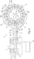
- a fuel injection device 1 according to a preferred embodiment of the invention is shown in detail.
- the fuel injection device 2 comprises a plurality of main burners 2 and a plurality of pilot burners 3. Each main burner 2 is assigned a pilot burner 3. A number of the main burner 2 is preferably straight.
- the main burners 2 are supplied with fuel via a main fuel line 20.
- the main fuel line 20 includes a first wiring harness 21, a second wiring harness 22, and a main distribution pipe 23. As shown in FIG Fig. 2 is apparent, the first wiring harness 21 and the second wiring harness 22 are each separately connected to the main distribution line 23.
- the main distribution line 23 is a closed loop, which is formed as a circle.
- the plurality of main burners 2 is preferably arranged on an inner circumference of the main distribution line 23.
- a first terminal 24 of the first wiring harness 21 on the main distribution pipe 23 and a second terminal 25 of the second wiring harness 22 and the main distribution pipe 23 are arranged on the main distribution pipe 23 such that the main distribution pipe 23 is divided into a first ring portion 23a and a second ring portion 23b which have a similar or equal line length. How out Fig. 2 it can be seen, therefore, the first terminal 24 and the second terminal 25 are preferably opposite each other by 180 ° to the main distribution line 23.
- each main burner 2 is connected via a branch line 26 to the main distribution line 23.
- a check valve 11 is arranged in each case. In this way, a pressure-controlled supply of the main burner in response to a pressure in the main distribution line 23 can be realized.
- the pilot burner 3 are arranged centrally in the main burners.
- the fuel injection device 1 further includes a fuel pilot line 30 including a pilot supply line 31 and a pilot distribution line 32.
- the pilot distribution line 32 is also a closed loop and in this embodiment also formed as a circular ring.
- Each pilot burner 3 is connected via a branch line 33 with the pilot distribution line 32 (see. Fig. 3 ).
- the fuel injector 1 further comprises an actuator 4 for providing fuel to the pilot burners and / or the main burners.
- the adjusting device 4 comprises a first valve unit 5 and a second valve unit 6. Further, a Control unit 10 is provided which controls the first valve unit 5 and the second valve unit 6.
- the reference numeral 9 denotes a tank connection, via which fuel from a tank, possibly via a fuel metering system, is supplied to the adjusting device 4.
- the fuel injection device 1 can now be operated in different operating modes. Depending on a power requirement of the gas turbine, for example, only the pilot burner 3 can be operated or, for example, at a high power requirement both the pilot burner 3 and the main burner 2 are operated.
- a first mode which in Fig. 2 is shown, only the pilot burner 3 are operated.
- the first valve unit 5 is brought into a position such that the tank connection 9 is connected exclusively to the second connection line 8.
- the second valve unit 6 is brought into a position in which the second connecting line 8 is connected to the first wiring harness 21 of the fuel main 20. Furthermore, it is ensured by the second valve unit 6 that the second wiring harness 22 is connected to the pilot supply line 31.
- fuel is supplied via the tank connection 9, as indicated by the arrow C, through the first valve unit 5 and the second valve unit 6 in the first wiring harness 21.
- the fuel is supplied to the main distribution line 23, which in Fig. 2 indicated by the arrows B.
- the fuel flow branches off via the two annular sections 23a, 23b to the second port 25.
- the fuel flows via the second wiring harness 22 back to the second valve unit 6.
- the second valve unit 6 is connected such that the second wiring harness 22 is connected to the pilot supply line 31 (see. Fig. 2 ).
- the fuel flowing back from the main distribution pipe 23 flows via the second wiring harness 22 into the pilot supply pipe 31 and from there into the pilot distribution pipe 32 to the pilot burners 3.
- the fuel is first fed via the first wiring harness 21 into the main distribution pipe 23 and back into the fuel pilot pipe 30 via the second wiring harness 22.
- the still cool fuel is first led from the tank connection 9 directly to the main distribution line 23, where it can cool the main burners 2, which also heat up in the exclusive pilot burner operation.
- the fuel flow absorbs some heat and is over the second Wiring harness 22 back to the second valve unit 6 and from there into the fuel pilot line 30 and fed to the pilot burners 3.
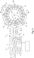
- Fig. 4 the fuel injection device 1 in a second mode in which both the plurality of main burners 2 and the plurality of pilot burners 3 is active.
- the control unit 10 is set up to set the adjusting device 4 in the second mode for the common pilot burner and main burner operation.
- the tank connection 9 is connected via the first valve unit 5 to the first connection line 7 and the second connection line 8 to the second valve unit 6.
- the first connection line 7 is connected to the first line section 21 and the second line section 22 of the main fuel line 20.
- the second connection line 8 is connected to the pilot supply line 31 via the second valve unit 6.
- the main distribution pipe 23 is supplied with fuel by the first and second wiring harnesses 21, 22. Cooling of the main burner and the pilot burner takes place in both cases by the relatively cool fuel from the tank.
- the second mode is used, for example, in aircraft gas turbines when climbing or cruising.
- a cooling of main burners 2, in particular in an exclusive pilot burner operation can be made possible.
- no additional lines are necessary, but by switching the connections between the first and second wiring harness 21, 22 of the fuel main 20, a cooling in the exclusive pilot burner operation can be achieved.
- a 3/2-way valve is used as the first valve unit 5 and in the second valve unit 6, a 5/2-way valve is used.
- valves in particular slide valves or a plurality of individual valves, which allow the corresponding implementation of the line connections usable.
- a fuel injector having a main fuel conduit 20 with first and second conduit branches 21, 22 is proposed, wherein one of the two conduit branches acts as a return conduit in an exclusive pilot burner operation To lead fuel from the main distribution line 23 back into the fuel pilot line 20.
- This allows a particularly compact and space-saving design, especially with low weight can be achieved.
Landscapes
- Engineering & Computer Science (AREA)
- Chemical & Material Sciences (AREA)
- Combustion & Propulsion (AREA)
- Mechanical Engineering (AREA)
- General Engineering & Computer Science (AREA)
- Feeding And Controlling Fuel (AREA)
Applications Claiming Priority (1)
| Application Number | Priority Date | Filing Date | Title |
|---|---|---|---|
| DE102017202800.9A DE102017202800A1 (de) | 2017-02-21 | 2017-02-21 | Brennstoffeinspritzvorrichtung für eine Gasturbine |
Publications (1)
| Publication Number | Publication Date |
|---|---|
| EP3364106A1 true EP3364106A1 (fr) | 2018-08-22 |
Family
ID=61249509
Family Applications (1)
| Application Number | Title | Priority Date | Filing Date |
|---|---|---|---|
| EP18157348.6A Withdrawn EP3364106A1 (fr) | 2017-02-21 | 2018-02-19 | Dispositif d'injection de carburant pour une turbine à gaz |
Country Status (3)
| Country | Link |
|---|---|
| US (1) | US20180238234A1 (fr) |
| EP (1) | EP3364106A1 (fr) |
| DE (1) | DE102017202800A1 (fr) |
Citations (4)
| Publication number | Priority date | Publication date | Assignee | Title |
|---|---|---|---|---|
| US20080271456A1 (en) * | 2007-05-04 | 2008-11-06 | Rolls-Royce Plc | Fuel supply system |
| EP2063087A2 (fr) * | 2007-11-20 | 2009-05-27 | Goodrich Control Systems Ltd | Dispositif d'alimentation étagée de carburant |
| GB2523126A (en) * | 2014-02-13 | 2015-08-19 | Rolls Royce Controls & Data Services Ltd | Fuel supply system |
| EP3070408A1 (fr) * | 2015-03-20 | 2016-09-21 | Rolls-Royce Controls and Data Services Limited | Système d'activation de combustion |
Family Cites Families (5)
| Publication number | Priority date | Publication date | Assignee | Title |
|---|---|---|---|---|
| US5187936A (en) * | 1990-10-17 | 1993-02-23 | General Electric Company | Continuous flow fuel circulation system |
| US5809771A (en) * | 1996-01-19 | 1998-09-22 | Woodward Governor Company | Aircraft engine fuel system |
| CN103748338B (zh) * | 2011-08-19 | 2016-05-25 | 伍德沃德公司 | 分流控制装置 |
| US9957891B2 (en) | 2011-09-09 | 2018-05-01 | General Electric Company | Fuel manifold cooling flow recirculation |
| GB2557599B (en) * | 2016-12-09 | 2019-05-15 | Rolls Royce Plc | Gas turbine engine fuel supply system having de-priming and re-priming sub-systems |
-
2017
- 2017-02-21 DE DE102017202800.9A patent/DE102017202800A1/de not_active Withdrawn
-
2018
- 2018-02-15 US US15/897,783 patent/US20180238234A1/en not_active Abandoned
- 2018-02-19 EP EP18157348.6A patent/EP3364106A1/fr not_active Withdrawn
Patent Citations (4)
| Publication number | Priority date | Publication date | Assignee | Title |
|---|---|---|---|---|
| US20080271456A1 (en) * | 2007-05-04 | 2008-11-06 | Rolls-Royce Plc | Fuel supply system |
| EP2063087A2 (fr) * | 2007-11-20 | 2009-05-27 | Goodrich Control Systems Ltd | Dispositif d'alimentation étagée de carburant |
| GB2523126A (en) * | 2014-02-13 | 2015-08-19 | Rolls Royce Controls & Data Services Ltd | Fuel supply system |
| EP3070408A1 (fr) * | 2015-03-20 | 2016-09-21 | Rolls-Royce Controls and Data Services Limited | Système d'activation de combustion |
Also Published As
| Publication number | Publication date |
|---|---|
| DE102017202800A1 (de) | 2018-08-23 |
| US20180238234A1 (en) | 2018-08-23 |
Similar Documents
| Publication | Publication Date | Title |
|---|---|---|
| DE102011054388B4 (de) | Einleiteinrichtung für ein Gasturbinensystem und Gasturbinensystem mit derartiger Einleiteinrichtung | |
| DE102015201805B4 (de) | Abgasturbolader | |
| DE112011104298B4 (de) | Gasturbinenmotor mit Sekundärluftstromkreis | |
| EP3059433A1 (fr) | Turbine a gaz avec refroidisseur d'huile dans l'habillage de la turbine | |
| CH702542A2 (de) | Düse für eine Gasturbine. | |
| EP2522831A2 (fr) | Moteur d'aéronef avec refroidisseur d'huile dans la nacelle de la turbine à gaz | |
| DE2547229A1 (de) | Verteilerkopf fuer abzweigluft | |
| EP3093447B1 (fr) | Rotor d'une turbine a gaz ayant un guidage d'air de refroidissement ameliore | |
| EP2532898A1 (fr) | Turbocompresseur axial | |
| DE102011115296A1 (de) | Zweistufige Aufladevorrichtung | |
| EP2799776A1 (fr) | Joint de brûleur pour tête de chambre de combustion de turbines à gaz et bouclier thermique | |
| EP4083511A1 (fr) | Buse injecteur de carburant pourvue de différents premiers et seconds orifices de sortie pour la fourniture d'un mélange hydrogène-air | |
| EP1245806A1 (fr) | Aube de turbine refroidie | |
| CH702543A2 (de) | Turbomaschine mit einer Einspritzdüsenanordnung. | |
| CH705822A1 (de) | Axialverdichter für eine Strömungsmaschine, insbesondere eine Gasturbine. | |
| EP1319806B1 (fr) | Dispositif de régulation de débit d'air | |
| EP2886807B1 (fr) | Bride de liaison refroidie d'une turbine à gaz | |
| EP3399144A1 (fr) | Moteur à réaction pourvu d'un dispositif de refroidissement | |
| EP3321589B1 (fr) | Buse de carburant d'une turbine à gaz dotée du générateur de tourbillons | |
| EP3540313A1 (fr) | Module de chambre de combustion comprenant un joint pour brûleur et une buse, ainsi qu'un dispositif de génération du courant d'appel | |
| EP3364106A1 (fr) | Dispositif d'injection de carburant pour une turbine à gaz | |
| EP1632650B1 (fr) | Turbine à vapeur | |
| DE102019213936A1 (de) | Brennkammerbaugruppe mit drehbarem Verstellelement an einer äußeren Brennkammerwandung für die Beeinflussung einer Mischluftströmung | |
| WO2017097665A1 (fr) | Turbine à gaz d'aéronef à tuyère de sortie variable d'un canal de flux secondaire | |
| DE4014976C1 (en) | Exhaust turbocharger with two-stage axial exhaust turbine - has duct section, adjacent to first turbine stage, as part of axially displaceable ring slider |
Legal Events
| Date | Code | Title | Description |
|---|---|---|---|
| PUAI | Public reference made under article 153(3) epc to a published international application that has entered the european phase |
Free format text: ORIGINAL CODE: 0009012 |
|
| STAA | Information on the status of an ep patent application or granted ep patent |
Free format text: STATUS: THE APPLICATION HAS BEEN PUBLISHED |
|
| AK | Designated contracting states |
Kind code of ref document: A1 Designated state(s): AL AT BE BG CH CY CZ DE DK EE ES FI FR GB GR HR HU IE IS IT LI LT LU LV MC MK MT NL NO PL PT RO RS SE SI SK SM TR |
|
| AX | Request for extension of the european patent |
Extension state: BA ME |
|
| STAA | Information on the status of an ep patent application or granted ep patent |
Free format text: STATUS: THE APPLICATION IS DEEMED TO BE WITHDRAWN |
|
| 18D | Application deemed to be withdrawn |
Effective date: 20190223 |