EP3364204B1 - Mittels ac-stark-effekt kontrolliertes nullfeld-magnetometer - Google Patents
Mittels ac-stark-effekt kontrolliertes nullfeld-magnetometer Download PDFInfo
- Publication number
- EP3364204B1 EP3364204B1 EP18156363.6A EP18156363A EP3364204B1 EP 3364204 B1 EP3364204 B1 EP 3364204B1 EP 18156363 A EP18156363 A EP 18156363A EP 3364204 B1 EP3364204 B1 EP 3364204B1
- Authority
- EP
- European Patent Office
- Prior art keywords
- optical
- magnetometer
- wavelength
- cell
- pumping
- Prior art date
- Legal status (The legal status is an assumption and is not a legal conclusion. Google has not performed a legal analysis and makes no representation as to the accuracy of the status listed.)
- Active
Links
- 230000005699 Stark effect Effects 0.000 title claims description 8
- 230000003287 optical effect Effects 0.000 claims description 95
- 230000005284 excitation Effects 0.000 claims description 65
- 238000005086 pumping Methods 0.000 claims description 35
- 238000005259 measurement Methods 0.000 claims description 16
- 238000000034 method Methods 0.000 claims description 13
- 230000007704 transition Effects 0.000 claims description 11
- 230000001276 controlling effect Effects 0.000 claims 1
- 230000006698 induction Effects 0.000 claims 1
- 230000001105 regulatory effect Effects 0.000 claims 1
- 230000000694 effects Effects 0.000 description 9
- 125000004429 atom Chemical group 0.000 description 8
- 239000007789 gas Substances 0.000 description 5
- SWQJXJOGLNCZEY-UHFFFAOYSA-N helium atom Chemical compound [He] SWQJXJOGLNCZEY-UHFFFAOYSA-N 0.000 description 5
- 238000001514 detection method Methods 0.000 description 4
- 230000010355 oscillation Effects 0.000 description 4
- 230000010287 polarization Effects 0.000 description 4
- 230000008569 process Effects 0.000 description 4
- 230000008878 coupling Effects 0.000 description 3
- 238000010168 coupling process Methods 0.000 description 3
- 238000005859 coupling reaction Methods 0.000 description 3
- 239000000463 material Substances 0.000 description 3
- 230000001360 synchronised effect Effects 0.000 description 3
- VYPSYNLAJGMNEJ-UHFFFAOYSA-N Silicium dioxide Chemical compound O=[Si]=O VYPSYNLAJGMNEJ-UHFFFAOYSA-N 0.000 description 2
- GWEVSGVZZGPLCZ-UHFFFAOYSA-N Titan oxide Chemical compound O=[Ti]=O GWEVSGVZZGPLCZ-UHFFFAOYSA-N 0.000 description 2
- 238000010521 absorption reaction Methods 0.000 description 2
- 230000008901 benefit Effects 0.000 description 2
- 230000033228 biological regulation Effects 0.000 description 2
- 238000010586 diagram Methods 0.000 description 2
- 238000001914 filtration Methods 0.000 description 2
- 239000001307 helium Substances 0.000 description 2
- 229910052734 helium Inorganic materials 0.000 description 2
- 238000003384 imaging method Methods 0.000 description 2
- 230000001965 increasing effect Effects 0.000 description 2
- 238000002347 injection Methods 0.000 description 2
- 239000007924 injection Substances 0.000 description 2
- 238000005404 magnetometry Methods 0.000 description 2
- 238000012986 modification Methods 0.000 description 2
- 230000004048 modification Effects 0.000 description 2
- 230000010349 pulsation Effects 0.000 description 2
- 230000006641 stabilisation Effects 0.000 description 2
- 238000011105 stabilization Methods 0.000 description 2
- 230000003068 static effect Effects 0.000 description 2
- 241000238366 Cephalopoda Species 0.000 description 1
- 230000005355 Hall effect Effects 0.000 description 1
- 210000004556 brain Anatomy 0.000 description 1
- 230000000747 cardiac effect Effects 0.000 description 1
- 238000001816 cooling Methods 0.000 description 1
- 238000000151 deposition Methods 0.000 description 1
- 230000008021 deposition Effects 0.000 description 1
- 230000001627 detrimental effect Effects 0.000 description 1
- 238000002059 diagnostic imaging Methods 0.000 description 1
- 238000005516 engineering process Methods 0.000 description 1
- 238000001704 evaporation Methods 0.000 description 1
- 230000008020 evaporation Effects 0.000 description 1
- 239000002360 explosive Substances 0.000 description 1
- 230000002349 favourable effect Effects 0.000 description 1
- 239000011521 glass Substances 0.000 description 1
- 238000010438 heat treatment Methods 0.000 description 1
- SWQJXJOGLNCZEY-IGMARMGPSA-N helium-4 atom Chemical group [4He] SWQJXJOGLNCZEY-IGMARMGPSA-N 0.000 description 1
- 238000005286 illumination Methods 0.000 description 1
- 230000001939 inductive effect Effects 0.000 description 1
- 238000002582 magnetoencephalography Methods 0.000 description 1
- 239000011159 matrix material Substances 0.000 description 1
- 238000000679 relaxometry Methods 0.000 description 1
- 239000000523 sample Substances 0.000 description 1
- 230000035945 sensitivity Effects 0.000 description 1
- 235000012239 silicon dioxide Nutrition 0.000 description 1
- 239000000377 silicon dioxide Substances 0.000 description 1
- 238000004544 sputter deposition Methods 0.000 description 1
- 239000002887 superconductor Substances 0.000 description 1
- 239000004408 titanium dioxide Substances 0.000 description 1
- 238000002834 transmittance Methods 0.000 description 1
- 238000003466 welding Methods 0.000 description 1
Images

Classifications
-
- G—PHYSICS
- G01—MEASURING; TESTING
- G01R—MEASURING ELECTRIC VARIABLES; MEASURING MAGNETIC VARIABLES
- G01R33/00—Arrangements or instruments for measuring magnetic variables
- G01R33/20—Arrangements or instruments for measuring magnetic variables involving magnetic resonance
- G01R33/24—Arrangements or instruments for measuring magnetic variables involving magnetic resonance for measuring direction or magnitude of magnetic fields or magnetic flux
- G01R33/26—Arrangements or instruments for measuring magnetic variables involving magnetic resonance for measuring direction or magnitude of magnetic fields or magnetic flux using optical pumping
Definitions
- the field of the invention is that of optically pumped magnetometers in zero field.
- the invention finds application in the imaging of biomagnetic fields, for example in magnetocardiography or magnetoencephalography, in particular by means of magnetometers used in a network.
- Optical pumping magnetometers are based on magnetic resonance between Zeeman lines amplified using optical pumping. These magnetometers use atomic gases confined in a cell (typically metastable helium or alkaline gases) as sensitive elements.
- the level of sensitivity (also called low noise) and accuracy achievable with such magnetometers are very remarkable and much more favorable than those of most other magnetic measurement technologies (fluxgate, Hall effect, magnetoresistance, etc.). Only the SQUID magnetometer has a similar noise, but it requires cryogenic cooling of the sensing element (using superconductors), which restricts its practical scope.
- the total zero magnetic field is obtained by generating magnetic compensation fields by current injection into appropriate coils surrounding the sensing element. These compensation fields cancel each of the components of the ambient magnetic field by means of closed-loop regulation of the injected currents.
- the measurement of the currents flowing in the coils makes it possible to deduce the fields which it is necessary to apply to cancel the different components of the ambient field, and thus to have the value of these different components.
- the zero-field servocontrol of a magnetometer can be detrimental. This is particularly the case when using magnetometers arranged according to a matrix network dedicated to the reconstruction of magnetic sources (for example for the imaging of the nervous or cardiac currents). Indeed, the application of compensation fields on a magnetometer impacts the fields seen by neighboring magnetometers (crosstalk effect) and thus disturbs the measurements made by neighboring magnetometers. In other applications (coupling to magnetostrictive sensors for example), the effect of the compensation fields can disturb the phenomena that one seeks to observe.
- An object of the invention is to make it possible to operate an optically pumped magnetometer in a "zero field" regime without having to generate compensating magnetic fields, while the ambient fields to be compensated are significantly greater than 100 nT. .
- the invention also relates to a magnetometry device comprising an array of magnetometers each in accordance with the invention, as well as to a method for controlling the null field of a magnetometer.
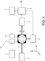
- the invention relates to an optically pumped magnetometer 10.
- the magnetometer 10 comprises a cell 1 filled with a gas, for example helium-4 or an alkaline gas, subjected to an ambient magnetic field B 0 .
- the ambient magnetic field B 0 is broken down into three components Bx, By and Bz each according to one of the measurement axes of the magnetometer x, y and z.
- the cell is illuminated by an optical pump source 2 capable of transmitting towards the cell a laser beam tuned to a pumping wavelength.
- the pumping wavelength is set on an atomic transition line, for example on line D 0 at 1083 nm in the case of helium-4.
- the pump beam can be linearly polarized in the z direction by means of a rectilinear polarizer (not shown).
- a photodetector 3 receives the laser beam having passed through the cell.
- the magnetometer 10 furthermore comprises an RF discharge system comprising an RF generator 4 and surge coils 5. It also comprises an RF frequency generator 7 which supplies two coils 6 orthogonal axes surrounding the cell. The coils 6 generate two RF fields orthogonal to the polarization direction of the pump beam. There is thus an RFx field and a RFy field on the x and y axes of respective pulses ⁇ and ⁇ .
- the magnetic moment of each atom in the cell undergoes resonant oscillations at frequencies that are multiple to that of the excitation RF fields.
- the amplitude of the oscillations makes it possible to measure the modulus of the collinear magnetic field at the radiofrequency field. More particularly, the oscillating RFx field at the ⁇ pulse is oriented along the x axis and the oscillating RFy field at the pulsation ⁇ is oriented along the y axis. This then results in a modulation of the transmitted light including pulsations ⁇ , w and ⁇ ⁇ ⁇ . These signals are respectively proportional to the components of the total magnetic field at the cell.
- the magnetometer 10 further comprises an electronic processing card 8 which processes the electrical signal at the output of the photodetector 8 to provide the values of the components B x , B y and B z of the ambient field B 0 .
- the card 8 is also slaved to the RF frequency generator 7 and drive the closed-loop servocontrol of the magnetometer to operate in a zero field.
- the electronic processing card 8 comprises a closed loop regulator which separates the resulting signal into three channels: a first channel Vx for detecting the signal at ⁇ / 2 ⁇ (x axis), a second channel Vy for detecting the signal at ⁇ / 2 ⁇ (y axis), and a third channel Vz for the detection of the signal at ⁇ ⁇ ⁇ / 2 ⁇ (z axis).
- the signal on each of the first and second channels is first amplified and then filtered with a bandpass filter BPx, BPy corresponding to the appropriate central frequency (ie corresponding to that of the applied RF field, respectively RFx and RFy).
- the signal obtained is then multiplied by a reference signal and processed by a synchronous detector DSx, DSy followed by a low-pass filter LPx, LPy.
- the third channel Vz uses two synchronous detections in series (at ⁇ / 2 ⁇ and then ⁇ / 2 ⁇ ) to go back to the amplitude modulated resonance at the frequencies ⁇ ⁇ ⁇ / 2 ⁇ (Z axis). It includes a BPz bandpass filter, a DSz synchronous detector and an LPz low-pass filter.
- Each of these three channels Vx, Vy, Vz comprises an integrator Ix, Iy, Iz for providing the closed-loop control by means of which the system locks in a zero field.
- the closed-loop control does not control the injection of current in a set of three orthogonal coils to generate magnetic fields of compensation of the ambient field.
- the Stark effect is exploited to induce, using optical excitations, the equivalent of these compensation fields.
- the invention exploits the phenomenon receiving the name of "lightshift” (or alternative Stark shift, or alternatively fictitious magnetic field induced by light) according to which optical excitations in circular polarization and slightly offset from the lines Atomic resonances induce behavior equivalent to that of a static magnetic field.
- lightshift or alternative Stark shift, or alternatively fictitious magnetic field induced by light
- This phenomenon is described in a quantitative way in the article W. Happer and BS Mathur, "Effective Operator Formalism in Optical Pumping," Phys. Rev., vol. 163, no. 1, pp. Nov. 12-25, 1967 .
- the magnetometer 10 integrates such an optical excitation source for each useful measurement axis, ie three sources in total, so as to induce a fictitious field Bcf x , Bcf y and Bcf z on each of the three measurement axes. x, y and z.
- the integrators Ix, Iy and Yz of the closed loop regulator of the processing card 8 supply control signals Ax, Ay and Ay to the optical excitation sources making it possible to operate in the field no. These include control signals relating to the amplitude of the light beams delivered by these excitation sources.
- the intensity of the light necessary to induce a fictitious field of the order of the terrestrial field is several W / cm 2 .
- This requires having high intensity sources the intensity of sources typically used in optical pump magnetometers being a few tens of mW).
- the luminous power of these beams must be dissipated, which induces a heating of the materials surrounding the cell, and therefore an increased difficulty for the thermal stabilization thereof.
- the invention proposes to play on the coupling of light with the atoms so as to make the "all-optical" compensation by Stark effect more efficient.
- the cell enclosing the sensitive element is disposed within a set of optical cavities (one cavity for each useful measurement axis, so a maximum of three).
- the confinement of light in these cavities has the effect of increasing the coupling between the light and the atoms, which makes it possible to induce significant fictitious fields (tens of ⁇ T) with low light amplitudes (a few mW or tens of mW) at the output of different sources of excitation.
- the closed loop servo device of the magnetometer for operating in a zero field comprises an optical cavity 11 delimited by mirrors M1, M2 in which the cell 1 is arranged.
- the light propagates along a direction of propagation in the cavity optical 11.
- the servo device further comprises an optical excitation source 9 configured to illuminate the at least one optical cavity 11 with a circularly polarized beam and tuned to an excitation wavelength offset with respect to the length of the pumping wave.
- an optical excitation source 9 configured to illuminate the at least one optical cavity 11 with a circularly polarized beam and tuned to an excitation wavelength offset with respect to the length of the pumping wave.
- the servo-control device is completed with the above-mentioned regulator which controls the optical excitation source so that it induces in the cell the equivalent of a compensating magnetic field opposite to the component of the ambient magnetic field. said direction of propagation of light.
- the optical cavity is arranged in such a way that the propagation direction of the light in the optical cavity corresponds to a measurement axis of the magnetometer.
- the optical cavity is more particularly bounded by a semi-reflecting mirror on the excitation source side and by a totally reflecting mirror.
- These mirrors may be interferometric filters made by a stack of thin layers (in the sense that their thickness is less than the wavelength of the light) of two materials having a high index contrast (for example titanium dioxide). and silicon dioxide).
- the layers of each of the materials are alternated with a thickness distribution calculated according to techniques well known in the art, with the aim, for example, of reflecting the wavelength of the light used for the effect compensation. Stark, but to transmit a substantial level of that used for the optical pumping of atoms.
- the optical cavity is a resonant cavity tuned to the excitation wavelength of the optical excitation source.
- This is for example a Fabry-Perot cavity whose transmittance as a function of the wavelength has regularly spaced peaks.
- the optical cavity is a multi-passage cavity which is distinguished from a resonant cavity in that there is no interference between the different passages of the light.
- the propagation direction of the light corresponds to the average of the propagation directions of each of the passages, the average being weighted according to the light intensity on each of the passages.
- the mirrors of the optical cavity may be formed directly on the walls of the cell, the latter having been subjected to a reflective treatment, for example an interferometric filter produced by a stack of thin layers such as that described above deposited directly on the walls of the cell.
- a reflective treatment for example an interferometric filter produced by a stack of thin layers such as that described above deposited directly on the walls of the cell.
- Deposition for example by evaporation or sputtering processes, can be carried out on the glass elements which will constitute the walls of the cell before they are assembled by molecular bonding or thermal welding to form a closed container. and waterproof.
- the optical excitation source 9 may comprise a laser configured to deliver a laser beam tuned to the excitation wavelength and a circular polarizer. It can be provided that the difference between the pumping wavelength and the excitation wavelength is between 0.25 and 2.5 times, preferably between 0.35 and 1.5 times, preferably 0.5 times, the optical width at mid-height of the line of the atomic transition activated by the optical pump source.
- the optical excitation source 9 comprises a laser configured to deliver a laser beam tuned to a tuned wavelength and an optical modulator capable of shifting the wavelength of the laser beam of the wavelength of d agreement to the excitation wavelength.
- the laser beam has two lateral wavelength bands respectively above and below the wavelength of agreement at ⁇ c ⁇ ⁇ , where ⁇ c corresponds to the wavelength of agreement and ⁇ represents the difference between the excitation wavelength and the pumping wavelength.
- the distance between the two lateral bands 2 * ⁇ is preferably between 0.5 and 5 times, more preferably between 0.7 and 3 times, and still more preferably equal to, the optical width at half height of the line of the atomic transition activated by the optical pumping source.
- the tuning wavelength may correspond to the pumping wavelength, in which case the atomic transition line is equidistant from the sidebands.
- the laser For the laser to be tuned to the wavelength of the atomic transition used for optical pumping, its wavelength is enslaved according to methods well known in the field of atomic physics, in particular a method based on the dichroism of the atomic vapor known in English as DAVLL for "Dichroic Atomic Vapor Laser Lock” and described for example in the following publication: B. Chéron, H. Gilles, J. Hamel, O. Moreau, and H. Sorel, "Laser frequency stabilization using Zeeman effect," Journal of Physics III, vol. 4, no. 2, pp. 401-406, 1994 .
- the lateral band above the tuning wavelength induces a fictitious field whose sign is opposite to the fictitious field induced by the sideband above the tuned wavelength.
- the optical excitation source further comprises an optical filter, made for example by an interferometric filter as described above, for filtering one of the two sidebands and a polarizer for circularly polarizing the unfiltered sideband.
- an optical filter made for example by an interferometric filter as described above, for filtering one of the two sidebands and a polarizer for circularly polarizing the unfiltered sideband.
- the optical excitation source comprises for this purpose two polarizing filters and a quarter wave plate arranged in cascade.
- the two polarizing filters consist of a first linear polarizer able to vertically polarize one of the sidebands and a second linear polariser able to horizontally polarize the other of the sidebands. These are, for example, wire grid polarizers .
- the quarter-wave plate circularly polarizes each of the lateral strips respectively in the counter-clockwise direction and in the clockwise direction. Insofar as the circularly polarized light on the right induces a fictitious field of opposite sign to that induced by circularly polarized light on the left, the output of the quarter-wave plate of inversely polarized sidebands and therefore corresponding to fields fictitious ones that are added.
- the invention is not limited to a magnetometer as such (alone or operated in a magnetometer array of a magnetometry device) but also extends to the zero field servocontrol method of such magnetometer.
- optical pumping According to this method, the closed-loop illumination of an optical cavity delimited by mirrors in which the cell is arranged by a circularly polarized beam and tuned to an excitation wavelength offset from at the pumping wavelength. This regulation is performed so as to induce in the cell, by Stark effect, the equivalent of a compensating magnetic field opposite to the ambient magnetic field in the direction of propagation of the light in the optical cavity.
- the invention finds application in medical imaging of the heart and brain. It is also used in processes involving important magnetic fields: detection of NMR / MRI signals, relaxometry, resonance nuclear quadrupole (RQN) for the detection of explosives; as well as as a probe for active magnetic shielding or magnetoelasticity measurements.
Landscapes
- Physics & Mathematics (AREA)
- Condensed Matter Physics & Semiconductors (AREA)
- General Physics & Mathematics (AREA)
- Measuring Magnetic Variables (AREA)
Claims (15)
- Magnetometer (10), umfassend eine Zelle (1), die mit einem Gas gefüllt ist, das einem Umgebungsmagnetfeld ausgesetzt ist, eine optische Pumpquelle (2), die dazu ausgelegt ist, in Richtung der Zelle einen Laserstrahl zu emittieren, der auf eine Pumpwellenlänge abgestimmt ist, einen Fotodetektor (3), der den Laserstrahl empfängt, der die Zelle durchlaufen hat, und ein System zur Regelung in geschlossener Schleife des Magnetometers, um es im Nullfeld funktionieren zu lassen, dadurch gekennzeichnet, dass das Regelsystem Folgendes umfasst:- einen optischen Hohlraum (11), der durch Spiegel (M1, M2) begrenzt ist, in dem die Zelle (1) angeordnet ist,- eine optische Anregungsquelle (9), die dazu konfiguriert ist, den optischen Hohlraum mit einem Strahl zu beleuchten, der zirkular polarisiert und auf eine Anregungswellenlänge abgestimmt ist, die bezüglich der Pumpwellenlänge derart versetzt ist, dass es ermöglicht wird, in der Zelle mittels Stark-Effekt das Äquivalent eines Magnetfelds zu induzieren, das entlang einer Ausbreitungsrichtung des Lichts in dem optischen Hohlraum orientiert ist, und- einen Regler in geschlossener Schleife (Vx, Vy, Vz), der mit dem Fotodetektor gekoppelt und dazu konfiguriert ist, die optische Anregungsquelle derart zu steuern, dass sie in der Zelle das Äquivalent eines magnetischen Kompensationsfelds entgegengesetzt zum Umgebungsmagnetfeld in der Ausbreitungsrichtung des Lichts induziert.
- Magnetometer nach Anspruch 1, bei dem der optische Hohlraum (11) ein Resonanzhohlraum ist, der auf die Anregungswellenlänge der optischen Anregungsquelle abgestimmt ist.
- Magnetometer nach Anspruch 1, bei dem der optische Hohlraum (11) ein Hohlraum mit mehreren Durchgängen ist.
- Magnetometer nach einem der Ansprüche 1 bis 3, bei dem die Spiegel (M1, M2) des optischen Hohlraums auf den Wänden der Zelle (1) gebildet sind.
- Magnetometer nach einem der Ansprüche 1 bis 4, bei dem der optische Hohlraum (11) derart ausgelegt ist, dass die Ausbreitungsrichtung des Lichts in dem optischen Hohlraum einer Messachse des Magnetometers entspricht.
- Magnetometer nach einem der Ansprüche 1 bis 5, bei dem die optische Anregungsquelle (9) einen Laser umfasst, der dazu konfiguriert ist, einen Laserstrahl zu liefern, der auf die Anregungswellenlänge abgestimmt ist, und einen Zirkularpolarisator.
- Magnetometer nach Anspruch 6, bei dem der Abstand zwischen der Pumpwellenlänge und der Anregungswellenlänge zwischen 0,25 und 2,5 Mal der optischen Breite auf halber Höhe der atomaren Übergangslinie enthalten ist, die durch die optische Pumpquelle aktiviert wird.
- Magnetometer nach einem der Ansprüche 1 bis 5, bei dem die optische Anregungsquelle (9) einen Laser umfasst, der dazu konfiguriert ist, einen Laserstrahl zu liefern, der auf die Pumpwellenlänge abgestimmt ist, und einen optischen Modulator, der dazu ausgelegt ist, die Wellenlänge des Laserstrahls von der Pumpwellenlänge in Richtung der Anregungswellenlänge zu versetzen.
- Magnetometer nach Anspruch 8, bei dem der Laserstrahl am Ausgang des Modulators zwei laterale Wellenlängenbänder über beziehungsweise unter der Pumpwellenlänge aufweist, und bei dem der Abstand zwischen den zwei lateralen Bändern zwischen 0,5 und 5 Mal der optischen Breite bei halber Höhe der atomaren Übergangslinie enthalten ist, die durch die optische Pumpquelle aktiviert wird.
- Magnetometer nach Anspruch 9, bei dem die optische Anregungsquelle (9) ferner ein optisches Filter umfasst, um eines der zwei lateralen Bänder zu filtern, sowie einen Polarisator, um das nicht gefilterte laterale Band zirkular zu polarisieren.
- Magnetometer nach Anspruch 9, bei dem die optische Anregungsquelle ferner zwei polarisierende Filter und eine Viertelwellenplatte umfasst, die in Kaskade angeordnet sind, wobei die zwei polarisierenden Filter bestehen aus einem ersten linearen Polarisator, der dazu ausgelegt ist, eines der lateralen Bänder vertikal zu polarisieren, und einem zweiten linearen Polarisator, der dazu ausgelegt ist, das andere der lateralen Bänder horizontal zu polarisieren, wobei die Viertelwellenplatte jedes der lateralen Bänder im Gegenuhrzeigersinn beziehungsweise im Uhrzeigersinn zirkular polarisiert.
- Magnetometer nach einem der Ansprüche 1 bis 11, bei dem der Regler einen Integrator (Iy, Iz, Ix) umfasst.
- Magnetometer nach einem der Ansprüche 1 bis 12, umfassend drei optische Hohlräume, die jeweils einer Messachse des Magnetometers zugeordnet sind und durch ihre eigene optische Anregungsquelle beleuchtet werden.
- Magnetometrievorrichtung, umfassend ein Netz von Magnetometern, von denen jedes dem Magnetometer nach einem der Ansprüche 1 bis 13 entspricht.
- Verfahren zum Regeln eines Magnetometers im Nullfeld, umfassend eine Zelle, die mit einem Gas gefüllt ist, das einem Umgebungsmagnetfeld ausgesetzt ist, eine optische Pumpquelle, die dazu ausgelegt ist, in Richtung der Zelle einen Laserstrahl zu emittieren, der auf eine Pumpwellenlänge abgestimmt ist, wobei das Verfahren die Regelung in geschlossener Schleife der Beleuchtung eines optischen Hohlraums umfasst, der durch Spiegel begrenzt ist, in dem die Zelle angeordnet ist, und zwar mittels eines Strahls, der zirkular polarisiert und auf eine Anregungswellenlänge abgestimmt ist, die bezüglich der Pumpwellenlänge derart versetzt ist, dass in der Zelle mittels Stark-Effekt das Äquivalent eines magnetischen Kompensationsfelds entgegengesetzt zum Umgebungsmagnetfeld in der Ausbreitungsrichtung des Lichts in den optischen Hohlraum induziert wird.
Applications Claiming Priority (1)
| Application Number | Priority Date | Filing Date | Title |
|---|---|---|---|
| FR1751217A FR3062922B1 (fr) | 2017-02-15 | 2017-02-15 | Magnetometre asservi en champ nul par effet stark alternatif exacerbe par une cavite optique |
Publications (2)
| Publication Number | Publication Date |
|---|---|
| EP3364204A1 EP3364204A1 (de) | 2018-08-22 |
| EP3364204B1 true EP3364204B1 (de) | 2019-09-11 |
Family
ID=59381344
Family Applications (1)
| Application Number | Title | Priority Date | Filing Date |
|---|---|---|---|
| EP18156363.6A Active EP3364204B1 (de) | 2017-02-15 | 2018-02-12 | Mittels ac-stark-effekt kontrolliertes nullfeld-magnetometer |
Country Status (2)
| Country | Link |
|---|---|
| EP (1) | EP3364204B1 (de) |
| FR (1) | FR3062922B1 (de) |
Cited By (1)
| Publication number | Priority date | Publication date | Assignee | Title |
|---|---|---|---|---|
| EP4675287A1 (de) * | 2024-07-03 | 2026-01-07 | Eagle Technology, LLC | Rydberg-sensor mit quantenfunkfrequenzkavität mit optischem verstärker und zugehörige verfahren |
Families Citing this family (5)
| Publication number | Priority date | Publication date | Assignee | Title |
|---|---|---|---|---|
| FR3090890B1 (fr) * | 2018-12-21 | 2021-10-08 | Commissariat Energie Atomique | Magnétomètre à pompage optique d’un élément sensible avec une lumière polarisée linéairement et multi-passage dans l’élément sensible |
| FR3093816B1 (fr) * | 2019-03-12 | 2021-04-16 | Commissariat Energie Atomique | Magnétomètre asservi en champ nul avec filtrage basse fréquence du champ de compensation |
| FR3110000B1 (fr) * | 2020-05-06 | 2022-05-27 | Commissariat Energie Atomique | Capteur de courant basé sur l’effet Faraday dans un gaz atomique |
| FR3110972B1 (fr) * | 2020-06-02 | 2022-10-07 | Commissariat Energie Atomique | Magnétomètre à pompage optique tri-axe pour mesure gradiométrique |
| FR3113737B1 (fr) | 2020-08-27 | 2022-10-07 | Commissariat Energie Atomique | Magnétomètre en polarisation elliptique avec deux composantes de champ radiofréquence pour détection de résonance paramétrique en absorption |
Family Cites Families (1)
| Publication number | Priority date | Publication date | Assignee | Title |
|---|---|---|---|---|
| KR101624482B1 (ko) * | 2014-10-24 | 2016-05-26 | 한국표준과학연구원 | 원자 자력계 및 그 동작 방법 |
-
2017
- 2017-02-15 FR FR1751217A patent/FR3062922B1/fr not_active Expired - Fee Related
-
2018
- 2018-02-12 EP EP18156363.6A patent/EP3364204B1/de active Active
Non-Patent Citations (1)
| Title |
|---|
| None * |
Cited By (1)
| Publication number | Priority date | Publication date | Assignee | Title |
|---|---|---|---|---|
| EP4675287A1 (de) * | 2024-07-03 | 2026-01-07 | Eagle Technology, LLC | Rydberg-sensor mit quantenfunkfrequenzkavität mit optischem verstärker und zugehörige verfahren |
Also Published As
| Publication number | Publication date |
|---|---|
| FR3062922A1 (fr) | 2018-08-17 |
| FR3062922B1 (fr) | 2019-04-19 |
| EP3364204A1 (de) | 2018-08-22 |
Similar Documents
| Publication | Publication Date | Title |
|---|---|---|
| EP3364204B1 (de) | Mittels ac-stark-effekt kontrolliertes nullfeld-magnetometer | |
| EP3524990B1 (de) | Vektor-magnetometer mit linearer und zirkulärer polarisation | |
| EP3115799B1 (de) | Optisch-isotropes magnetometer | |
| EP3730959B1 (de) | Magnetometer gesteuert bei feldstärke null mit niedrigfrequenzfilterung des kompensationsfelds | |
| EP0462002B1 (de) | Resonanzmagnetometer mit optischen Pumpen, das unterschiedliche Polarisationszustände verwendet | |
| Shelby et al. | Generation of squeezed states of light with a fiber-optic ring interferometer | |
| EP2824470B1 (de) | Messverfahren und -vorrichtung zur Messung eines Magnetfelds mittels synchronisierter Anregungen | |
| CA1283950C (fr) | Magnetometre a helium pompe par laser | |
| EP3454139B1 (de) | Optisches messsystem mit stabilisierter davll-steuerung und verfahren dazu | |
| EP2426563A1 (de) | Kalibrierungsverfahren für ein Gerät mit Atomantrieb | |
| Akhmedzhanov et al. | Electromagnetically induced transparency in an isotopically purified Nd 3+: YLiF 4 crystal | |
| EP3771917B1 (de) | Optisch gepumptes magnetometer | |
| Makarov et al. | All-optical atomic magnetometry using an elliptically polarized amplitude-modulated light wave | |
| EP3702797B1 (de) | Isotropes, skalares und rein optisches magnetometer | |
| Vershovskii et al. | Methods of parametric resonance excitation in the scheme of an optical magnetometric sensor | |
| EP3650877A1 (de) | Kompaktes magnetometer mit hanle-effekt | |
| WO2022084698A1 (en) | Optical magnetometer | |
| EP3961236B1 (de) | Elliptisch polarisiertes magnetometer mit zwei hochfrequenz-feldkomponenten zur detektion der parametrischen absorptionsresonanz | |
| EP3654048A1 (de) | Magnetometer in winkelversetzter ausrichtung zwischen der polarisation der pumpen- und der sondenstrahlen | |
| CN118837802A (zh) | 用于方向敏感地测量磁场的磁力计单元和具有磁力计单元的梯度计单元 | |
| Zapasskii et al. | Cavity-enhanced optical anisotropy and all-optical spin noise spectrometer | |
| WO1991007668A1 (fr) | Cellule de vapeurs atomiques ou moleculaires pour pompage optique et magnetometre ou gyroscope utilisant une telle cellule | |
| EP3919928A1 (de) | Dreiachsiges optisch gepumptes magnetometer für gradiometrische messungen | |
| Zeng et al. | A design of cesium atomic magnetometer based on circular dichroism | |
| Day | Investigation of sign reversal between electromagnetically induced transparency and absorption in atomic vapor |
Legal Events
| Date | Code | Title | Description |
|---|---|---|---|
| PUAI | Public reference made under article 153(3) epc to a published international application that has entered the european phase |
Free format text: ORIGINAL CODE: 0009012 |
|
| STAA | Information on the status of an ep patent application or granted ep patent |
Free format text: STATUS: REQUEST FOR EXAMINATION WAS MADE |
|
| 17P | Request for examination filed |
Effective date: 20180212 |
|
| AK | Designated contracting states |
Kind code of ref document: A1 Designated state(s): AL AT BE BG CH CY CZ DE DK EE ES FI FR GB GR HR HU IE IS IT LI LT LU LV MC MK MT NL NO PL PT RO RS SE SI SK SM TR |
|
| AX | Request for extension of the european patent |
Extension state: BA ME |
|
| GRAP | Despatch of communication of intention to grant a patent |
Free format text: ORIGINAL CODE: EPIDOSNIGR1 |
|
| STAA | Information on the status of an ep patent application or granted ep patent |
Free format text: STATUS: GRANT OF PATENT IS INTENDED |
|
| RIC1 | Information provided on ipc code assigned before grant |
Ipc: G01R 33/26 20060101AFI20190307BHEP |
|
| INTG | Intention to grant announced |
Effective date: 20190403 |
|
| GRAS | Grant fee paid |
Free format text: ORIGINAL CODE: EPIDOSNIGR3 |
|
| GRAA | (expected) grant |
Free format text: ORIGINAL CODE: 0009210 |
|
| STAA | Information on the status of an ep patent application or granted ep patent |
Free format text: STATUS: THE PATENT HAS BEEN GRANTED |
|
| AK | Designated contracting states |
Kind code of ref document: B1 Designated state(s): AL AT BE BG CH CY CZ DE DK EE ES FI FR GB GR HR HU IE IS IT LI LT LU LV MC MK MT NL NO PL PT RO RS SE SI SK SM TR |
|
| REG | Reference to a national code |
Ref country code: GB Ref legal event code: FG4D Free format text: NOT ENGLISH |
|
| REG | Reference to a national code |
Ref country code: CH Ref legal event code: EP |
|
| REG | Reference to a national code |
Ref country code: AT Ref legal event code: REF Ref document number: 1179146 Country of ref document: AT Kind code of ref document: T Effective date: 20190915 |
|
| REG | Reference to a national code |
Ref country code: DE Ref legal event code: R096 Ref document number: 602018000589 Country of ref document: DE Ref country code: IE Ref legal event code: FG4D Free format text: LANGUAGE OF EP DOCUMENT: FRENCH |
|
| REG | Reference to a national code |
Ref country code: NL Ref legal event code: MP Effective date: 20190911 |
|
| REG | Reference to a national code |
Ref country code: LT Ref legal event code: MG4D |
|
| PG25 | Lapsed in a contracting state [announced via postgrant information from national office to epo] |
Ref country code: FI Free format text: LAPSE BECAUSE OF FAILURE TO SUBMIT A TRANSLATION OF THE DESCRIPTION OR TO PAY THE FEE WITHIN THE PRESCRIBED TIME-LIMIT Effective date: 20190911 Ref country code: LT Free format text: LAPSE BECAUSE OF FAILURE TO SUBMIT A TRANSLATION OF THE DESCRIPTION OR TO PAY THE FEE WITHIN THE PRESCRIBED TIME-LIMIT Effective date: 20190911 Ref country code: BG Free format text: LAPSE BECAUSE OF FAILURE TO SUBMIT A TRANSLATION OF THE DESCRIPTION OR TO PAY THE FEE WITHIN THE PRESCRIBED TIME-LIMIT Effective date: 20191211 Ref country code: NO Free format text: LAPSE BECAUSE OF FAILURE TO SUBMIT A TRANSLATION OF THE DESCRIPTION OR TO PAY THE FEE WITHIN THE PRESCRIBED TIME-LIMIT Effective date: 20191211 Ref country code: HR Free format text: LAPSE BECAUSE OF FAILURE TO SUBMIT A TRANSLATION OF THE DESCRIPTION OR TO PAY THE FEE WITHIN THE PRESCRIBED TIME-LIMIT Effective date: 20190911 Ref country code: SE Free format text: LAPSE BECAUSE OF FAILURE TO SUBMIT A TRANSLATION OF THE DESCRIPTION OR TO PAY THE FEE WITHIN THE PRESCRIBED TIME-LIMIT Effective date: 20190911 |
|
| PG25 | Lapsed in a contracting state [announced via postgrant information from national office to epo] |
Ref country code: AL Free format text: LAPSE BECAUSE OF FAILURE TO SUBMIT A TRANSLATION OF THE DESCRIPTION OR TO PAY THE FEE WITHIN THE PRESCRIBED TIME-LIMIT Effective date: 20190911 Ref country code: ES Free format text: LAPSE BECAUSE OF FAILURE TO SUBMIT A TRANSLATION OF THE DESCRIPTION OR TO PAY THE FEE WITHIN THE PRESCRIBED TIME-LIMIT Effective date: 20190911 Ref country code: GR Free format text: LAPSE BECAUSE OF FAILURE TO SUBMIT A TRANSLATION OF THE DESCRIPTION OR TO PAY THE FEE WITHIN THE PRESCRIBED TIME-LIMIT Effective date: 20191212 Ref country code: RS Free format text: LAPSE BECAUSE OF FAILURE TO SUBMIT A TRANSLATION OF THE DESCRIPTION OR TO PAY THE FEE WITHIN THE PRESCRIBED TIME-LIMIT Effective date: 20190911 Ref country code: LV Free format text: LAPSE BECAUSE OF FAILURE TO SUBMIT A TRANSLATION OF THE DESCRIPTION OR TO PAY THE FEE WITHIN THE PRESCRIBED TIME-LIMIT Effective date: 20190911 |
|
| REG | Reference to a national code |
Ref country code: AT Ref legal event code: MK05 Ref document number: 1179146 Country of ref document: AT Kind code of ref document: T Effective date: 20190911 |
|
| PG25 | Lapsed in a contracting state [announced via postgrant information from national office to epo] |
Ref country code: EE Free format text: LAPSE BECAUSE OF FAILURE TO SUBMIT A TRANSLATION OF THE DESCRIPTION OR TO PAY THE FEE WITHIN THE PRESCRIBED TIME-LIMIT Effective date: 20190911 Ref country code: PL Free format text: LAPSE BECAUSE OF FAILURE TO SUBMIT A TRANSLATION OF THE DESCRIPTION OR TO PAY THE FEE WITHIN THE PRESCRIBED TIME-LIMIT Effective date: 20190911 Ref country code: IT Free format text: LAPSE BECAUSE OF FAILURE TO SUBMIT A TRANSLATION OF THE DESCRIPTION OR TO PAY THE FEE WITHIN THE PRESCRIBED TIME-LIMIT Effective date: 20190911 Ref country code: AT Free format text: LAPSE BECAUSE OF FAILURE TO SUBMIT A TRANSLATION OF THE DESCRIPTION OR TO PAY THE FEE WITHIN THE PRESCRIBED TIME-LIMIT Effective date: 20190911 Ref country code: PT Free format text: LAPSE BECAUSE OF FAILURE TO SUBMIT A TRANSLATION OF THE DESCRIPTION OR TO PAY THE FEE WITHIN THE PRESCRIBED TIME-LIMIT Effective date: 20200113 Ref country code: RO Free format text: LAPSE BECAUSE OF FAILURE TO SUBMIT A TRANSLATION OF THE DESCRIPTION OR TO PAY THE FEE WITHIN THE PRESCRIBED TIME-LIMIT Effective date: 20190911 Ref country code: NL Free format text: LAPSE BECAUSE OF FAILURE TO SUBMIT A TRANSLATION OF THE DESCRIPTION OR TO PAY THE FEE WITHIN THE PRESCRIBED TIME-LIMIT Effective date: 20190911 |
|
| PG25 | Lapsed in a contracting state [announced via postgrant information from national office to epo] |
Ref country code: SK Free format text: LAPSE BECAUSE OF FAILURE TO SUBMIT A TRANSLATION OF THE DESCRIPTION OR TO PAY THE FEE WITHIN THE PRESCRIBED TIME-LIMIT Effective date: 20190911 Ref country code: CZ Free format text: LAPSE BECAUSE OF FAILURE TO SUBMIT A TRANSLATION OF THE DESCRIPTION OR TO PAY THE FEE WITHIN THE PRESCRIBED TIME-LIMIT Effective date: 20190911 Ref country code: IS Free format text: LAPSE BECAUSE OF FAILURE TO SUBMIT A TRANSLATION OF THE DESCRIPTION OR TO PAY THE FEE WITHIN THE PRESCRIBED TIME-LIMIT Effective date: 20200224 Ref country code: SM Free format text: LAPSE BECAUSE OF FAILURE TO SUBMIT A TRANSLATION OF THE DESCRIPTION OR TO PAY THE FEE WITHIN THE PRESCRIBED TIME-LIMIT Effective date: 20190911 |
|
| REG | Reference to a national code |
Ref country code: DE Ref legal event code: R097 Ref document number: 602018000589 Country of ref document: DE |
|
| PLBE | No opposition filed within time limit |
Free format text: ORIGINAL CODE: 0009261 |
|
| STAA | Information on the status of an ep patent application or granted ep patent |
Free format text: STATUS: NO OPPOSITION FILED WITHIN TIME LIMIT |
|
| PG2D | Information on lapse in contracting state deleted |
Ref country code: IS |
|
| PG25 | Lapsed in a contracting state [announced via postgrant information from national office to epo] |
Ref country code: DK Free format text: LAPSE BECAUSE OF FAILURE TO SUBMIT A TRANSLATION OF THE DESCRIPTION OR TO PAY THE FEE WITHIN THE PRESCRIBED TIME-LIMIT Effective date: 20190911 Ref country code: IS Free format text: LAPSE BECAUSE OF FAILURE TO SUBMIT A TRANSLATION OF THE DESCRIPTION OR TO PAY THE FEE WITHIN THE PRESCRIBED TIME-LIMIT Effective date: 20200112 |
|
| 26N | No opposition filed |
Effective date: 20200615 |
|
| PG25 | Lapsed in a contracting state [announced via postgrant information from national office to epo] |
Ref country code: SI Free format text: LAPSE BECAUSE OF FAILURE TO SUBMIT A TRANSLATION OF THE DESCRIPTION OR TO PAY THE FEE WITHIN THE PRESCRIBED TIME-LIMIT Effective date: 20190911 |
|
| REG | Reference to a national code |
Ref country code: BE Ref legal event code: MM Effective date: 20200229 |
|
| PG25 | Lapsed in a contracting state [announced via postgrant information from national office to epo] |
Ref country code: LU Free format text: LAPSE BECAUSE OF NON-PAYMENT OF DUE FEES Effective date: 20200212 Ref country code: MC Free format text: LAPSE BECAUSE OF FAILURE TO SUBMIT A TRANSLATION OF THE DESCRIPTION OR TO PAY THE FEE WITHIN THE PRESCRIBED TIME-LIMIT Effective date: 20190911 |
|
| PG25 | Lapsed in a contracting state [announced via postgrant information from national office to epo] |
Ref country code: IE Free format text: LAPSE BECAUSE OF NON-PAYMENT OF DUE FEES Effective date: 20200212 |
|
| PG25 | Lapsed in a contracting state [announced via postgrant information from national office to epo] |
Ref country code: BE Free format text: LAPSE BECAUSE OF NON-PAYMENT OF DUE FEES Effective date: 20200229 |
|
| PGFP | Annual fee paid to national office [announced via postgrant information from national office to epo] |
Ref country code: FR Payment date: 20210226 Year of fee payment: 4 |
|
| PGFP | Annual fee paid to national office [announced via postgrant information from national office to epo] |
Ref country code: DE Payment date: 20210209 Year of fee payment: 4 |
|
| PG25 | Lapsed in a contracting state [announced via postgrant information from national office to epo] |
Ref country code: CH Free format text: LAPSE BECAUSE OF NON-PAYMENT OF DUE FEES Effective date: 20210228 Ref country code: LI Free format text: LAPSE BECAUSE OF NON-PAYMENT OF DUE FEES Effective date: 20210228 |
|
| PG25 | Lapsed in a contracting state [announced via postgrant information from national office to epo] |
Ref country code: TR Free format text: LAPSE BECAUSE OF FAILURE TO SUBMIT A TRANSLATION OF THE DESCRIPTION OR TO PAY THE FEE WITHIN THE PRESCRIBED TIME-LIMIT Effective date: 20190911 Ref country code: MT Free format text: LAPSE BECAUSE OF FAILURE TO SUBMIT A TRANSLATION OF THE DESCRIPTION OR TO PAY THE FEE WITHIN THE PRESCRIBED TIME-LIMIT Effective date: 20190911 Ref country code: CY Free format text: LAPSE BECAUSE OF FAILURE TO SUBMIT A TRANSLATION OF THE DESCRIPTION OR TO PAY THE FEE WITHIN THE PRESCRIBED TIME-LIMIT Effective date: 20190911 |
|
| PG25 | Lapsed in a contracting state [announced via postgrant information from national office to epo] |
Ref country code: MK Free format text: LAPSE BECAUSE OF FAILURE TO SUBMIT A TRANSLATION OF THE DESCRIPTION OR TO PAY THE FEE WITHIN THE PRESCRIBED TIME-LIMIT Effective date: 20190911 |
|
| REG | Reference to a national code |
Ref country code: DE Ref legal event code: R119 Ref document number: 602018000589 Country of ref document: DE |
|
| GBPC | Gb: european patent ceased through non-payment of renewal fee |
Effective date: 20220212 |
|
| PG25 | Lapsed in a contracting state [announced via postgrant information from national office to epo] |
Ref country code: FR Free format text: LAPSE BECAUSE OF NON-PAYMENT OF DUE FEES Effective date: 20220228 |
|
| PG25 | Lapsed in a contracting state [announced via postgrant information from national office to epo] |
Ref country code: GB Free format text: LAPSE BECAUSE OF NON-PAYMENT OF DUE FEES Effective date: 20220212 Ref country code: DE Free format text: LAPSE BECAUSE OF NON-PAYMENT OF DUE FEES Effective date: 20220901 |