EP3364227A1 - Dispositif de commande de position de faisceau lumineux - Google Patents
Dispositif de commande de position de faisceau lumineux Download PDFInfo
- Publication number
- EP3364227A1 EP3364227A1 EP16855196.8A EP16855196A EP3364227A1 EP 3364227 A1 EP3364227 A1 EP 3364227A1 EP 16855196 A EP16855196 A EP 16855196A EP 3364227 A1 EP3364227 A1 EP 3364227A1
- Authority
- EP
- European Patent Office
- Prior art keywords
- light beam
- main body
- position control
- dielectric elastomer
- voltage
- Prior art date
- Legal status (The legal status is an assumption and is not a legal conclusion. Google has not performed a legal analysis and makes no representation as to the accuracy of the status listed.)
- Withdrawn
Links
- 229920002595 Dielectric elastomer Polymers 0.000 claims abstract description 42
- 238000000034 method Methods 0.000 claims description 6
- 238000005516 engineering process Methods 0.000 abstract description 12
- 230000003287 optical effect Effects 0.000 abstract description 10
- 238000006073 displacement reaction Methods 0.000 description 9
- 230000000694 effects Effects 0.000 description 4
- 230000002093 peripheral effect Effects 0.000 description 4
- 239000000463 material Substances 0.000 description 3
- 238000003754 machining Methods 0.000 description 2
- 229920003023 plastic Polymers 0.000 description 2
- 229910001111 Fine metal Inorganic materials 0.000 description 1
- 230000007423 decrease Effects 0.000 description 1
- 230000001419 dependent effect Effects 0.000 description 1
- 238000012986 modification Methods 0.000 description 1
- 230000004048 modification Effects 0.000 description 1
- 239000012811 non-conductive material Substances 0.000 description 1
- 239000004033 plastic Substances 0.000 description 1
- 238000001771 vacuum deposition Methods 0.000 description 1
Images




Classifications
-
- G—PHYSICS
- G02—OPTICS
- G02B—OPTICAL ELEMENTS, SYSTEMS OR APPARATUS
- G02B26/00—Optical devices or arrangements for the control of light using movable or deformable optical elements
- G02B26/08—Optical devices or arrangements for the control of light using movable or deformable optical elements for controlling the direction of light
- G02B26/0875—Optical devices or arrangements for the control of light using movable or deformable optical elements for controlling the direction of light by means of one or more refracting elements
-
- F—MECHANICAL ENGINEERING; LIGHTING; HEATING; WEAPONS; BLASTING
- F21—LIGHTING
- F21V—FUNCTIONAL FEATURES OR DETAILS OF LIGHTING DEVICES OR SYSTEMS THEREOF; STRUCTURAL COMBINATIONS OF LIGHTING DEVICES WITH OTHER ARTICLES, NOT OTHERWISE PROVIDED FOR
- F21V14/00—Controlling the distribution of the light emitted by adjustment of elements
- F21V14/02—Controlling the distribution of the light emitted by adjustment of elements by movement of light sources
-
- G—PHYSICS
- G02—OPTICS
- G02B—OPTICAL ELEMENTS, SYSTEMS OR APPARATUS
- G02B26/00—Optical devices or arrangements for the control of light using movable or deformable optical elements
- G02B26/08—Optical devices or arrangements for the control of light using movable or deformable optical elements for controlling the direction of light
-
- G—PHYSICS
- G02—OPTICS
- G02B—OPTICAL ELEMENTS, SYSTEMS OR APPARATUS
- G02B26/00—Optical devices or arrangements for the control of light using movable or deformable optical elements
- G02B26/08—Optical devices or arrangements for the control of light using movable or deformable optical elements for controlling the direction of light
- G02B26/10—Scanning systems
-
- G—PHYSICS
- G02—OPTICS
- G02F—OPTICAL DEVICES OR ARRANGEMENTS FOR THE CONTROL OF LIGHT BY MODIFICATION OF THE OPTICAL PROPERTIES OF THE MEDIA OF THE ELEMENTS INVOLVED THEREIN; NON-LINEAR OPTICS; FREQUENCY-CHANGING OF LIGHT; OPTICAL LOGIC ELEMENTS; OPTICAL ANALOGUE/DIGITAL CONVERTERS
- G02F1/00—Devices or arrangements for the control of the intensity, colour, phase, polarisation or direction of light arriving from an independent light source, e.g. switching, gating or modulating; Non-linear optics
- G02F1/29—Devices or arrangements for the control of the intensity, colour, phase, polarisation or direction of light arriving from an independent light source, e.g. switching, gating or modulating; Non-linear optics for the control of the position or the direction of light beams, i.e. deflection
-
- G—PHYSICS
- G03—PHOTOGRAPHY; CINEMATOGRAPHY; ANALOGOUS TECHNIQUES USING WAVES OTHER THAN OPTICAL WAVES; ELECTROGRAPHY; HOLOGRAPHY
- G03B—APPARATUS OR ARRANGEMENTS FOR TAKING PHOTOGRAPHS OR FOR PROJECTING OR VIEWING THEM; APPARATUS OR ARRANGEMENTS EMPLOYING ANALOGOUS TECHNIQUES USING WAVES OTHER THAN OPTICAL WAVES; ACCESSORIES THEREFOR
- G03B2205/00—Adjustment of optical system relative to image or object surface other than for focusing
- G03B2205/0053—Driving means for the movement of one or more optical element
- G03B2205/0084—Driving means for the movement of one or more optical element using other types of actuators
Definitions
- the present invention relates to technology for controlling position of a light beam.
- this technology controls angle (direction) of a light beam that passes through the electro-optical element, and so if the distance between the electro-optical element and an object the light beam is directed at becomes large, there is a tendency for resolution to deteriorate. With this technology, therefore, there is a problem that maintaining stable resolution is difficult.
- Non-patent publication 1 M. Bozlar, et al, "Dielectric elastomer actuators with elastomeric electrodes," Applied Physics Letters, 101.9 (2012 )
- the present invention has been conceived in view of the above-described circumstances.
- One main objective of the present invention is to provide technology to control position of a light beam using a dielectric elastomer itself as an optical element.
- Another objective of the present invention is to provide technology that is capable of maintaining high resolution, even when an object is at a distance, by controlling position of a light beam.
- a light beam position control device comprising: a main body and a power feed section, wherein the main body is constituted by an dielectric elastomer, the dielectric elastomer is made substantially transparent to a light beam that is an object of control, the dielectric elastomer is made to have a refractive index that is different to refractive index of a medium that exists around the main body, and that the light beam will pass through, and the power feed section is configured to cause thickness of the main body to change by applying a voltage to the body.
- the power feed section comprises a power supply and an electrode, with the electrode being attached to a surface of the main body, and the power supply being configured to apply a voltage to the main body by means of the electrode.
- the light beam position control device of aspect 2 wherein the electrode is arranged around positions where the light beam passes through, and in this way the light beam is capable of passing through the main body without passing through the electrode.
- the power feed section further comprises a storage section, the storage section storing correspondence information of a voltage value applied to the main body and amount of deformation of the main body, and the power feed section being configured to perform power feed from the power supply to the main body by specifying voltage value for an intended amount of deformation, based on the correspondence information.
- the second main body is constituted by a dielectric elastomer
- the dielectric elastomer of the second main body is made substantially transparent to a light beam that has passed through the first main body
- the dielectric elastomer of the second main body is made to have a refractive index that is different to refractive index of a medium that exists around the second
- a light beam position control method that uses a light beam position control device comprising a main body and a power feed section, wherein the main body is constituted by an dielectric elastomer, the dielectric elastomer is made substantially transparent to a light beam that is an object of control, the dielectric elastomer is made to have a refractive index that is different to refractive index of a medium that exists around the main body, and that the light beam will pass through, and the power feed section is configured to cause thickness of the main body to change by applying a voltage to the main body, the light beam position control method comprising: a step of applying voltage from the power feed section to the main body, and a step of causing the light beam to pass through the main body, that has been deformed by application of the voltage, so as to change emission position of the light beam from the main body, before and after the deformation.
- a light beam position control device of a first embodiment of the present invention will be described in the following with reference to the attached drawings.
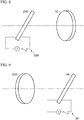
- the light beam position control device of this embodiment comprises a main body 10 and a power feed section 20 (refer to Fig. 1 ). It should be noted that although Fig. 1 shows a cross-section of the main body 10, in this drawing dimensions are shown in an exaggerated fashion to simplify understanding, and proportions are not accurate.
- the main body 10 is constituted by a dielectric elastomer.
- This dielectric elastomer is made substantially transparent to a light beam that is an object of control.
- the dielectric elastomer is made to have a refractive index that is different to refractive index of a medium that exists around the main body 10, and that the light beam will pass through.
- a refractive index that is different to refractive index of a medium that exists around the main body 10, and that the light beam will pass through.
- around the main body 10 is air.
- VHB4910 (refractive index 1.47) manufactured by 3M Ltd. can be used as the dielectric elastomer capable of being used with this embodiment, but this is not limiting.
- shape of the main body 10 (namely the shape of the dielectric elastomer) is a made a thin belt shape extending in one direction (specifically, a direction perpendicular to the paper surface of Fig. 1 ), but is not particularly limited to this shape. In other words, it may be a shape with which light beam position control can be executed.
- the feed section 20 is configured to cause change in the thickness of the main body 10 by applying voltage to the main body 10.
- the feed section 20 of this embodiment comprises a power supply 21, electrodes 22, and a switch 23.
- the electrodes 22 are respectively attached the surfaces (upper and lower surfaces in Fig. 1 ) of the main body 10. It is desirable for the electrodes 22 to be of a material that is transparent to wavelength of items used. It is possible to use transparent conductive gel, for example, as the material of the electrodes 22, but this is not limiting. As a transparent conductive gel, "Technogel G-CR manufactured by Sekisui Plastics Co. Ltd.” can be exemplified, but this is not limiting.
- the power supply 21 is configured to apply voltage to the main body 10 via the switch 23 and electrodes 22.
- a constant voltage dc power supply can be used as the power supply 21 in this embodiment. More specifically, as the power supply 21 it is possible to use a power supply device that can be voltage controlled with 16 bits in a range of about 1 to 10 kV, for example, by a suitable computer (for example, a suitable DA board), but this is only an example and the present invention is not limited to this. The most important thing is that the power supply 21 can supply a given voltage value at the required resolution.
- the switch 23 is for switching supply of power from the power supply 21 to the main body 10 on and off. It should be noted that Fig. 1 shows the switch 23 in an off state.
- a mechanical switch or an electronic switch for example, a transistor or thyristor, for example, can be used as the switch 23, but this is not limiting.
- the main requirement for the switch 23 of this embodiment is that it has a function of switching supply of power from the power supply 21 on and off.
- displacement ⁇ is a function of thickness d.
- air is assumed as a medium around the main body, and refractive index of air is 1.
- a range taken by angle of inclination i is assumed to be 0 ⁇ i ⁇ /2(rad) with this embodiment.
- a light beam position control method of this embodiment will be described on the premise of the above description.
- displacement amount of the light beam is changed from ⁇ 0 to ⁇ 1 , accompanying change in thickness d of the main body 10 (refer to Fig. 3 ). It should be noted that if it is assumed that the refractive index of the material is equal at the incident side and the emission side, emission angle of the light beam in Fig. 3 can be considered to be substantially the same as the emission angle of the light beam in Fig. 2 .
- the device of this embodiment it becomes possible to control only position of a light beam without changing the direction of the light beam.
- technology that changes angle of a light beam there is a problem that in a case where distance to an object (or camera) is far, resolution of the light beam position is deteriorated.
- the position of the light beam is changed, and so there is the advantage that it becomes possible to control light beam position at a high resolution regardless of distance.
- the device of this embodiment it as possible to control a voltage value supplied to the main body 10 with high resolution, by using digital control with a computer, for example. Accordingly, if a relationship between voltage value and amount of deformation of the main body 10 is known, there is the advantage that it is possible to control the light beam position with high resolution.
- is preferably obtained experimentally in advance, and a correspondence relationship between the two stored in a storage section (not shown) .
- light beam position control with good precision becomes possible even if the relationship between voltage value and light beam position change amount is nonlinear. Also, even if the effect on light beam position due to the electrodes 22 cannot be ignored, light beam position control so as to suppress or cancel the effect of the electrodes 22 becomes simple.
- a light beam position control device of a second embodiment of the present invention will be described based on Fig. 4 and Fig. 5 .
- structural elements that are basically common to the device of the first embodiment described above will be assigned the same reference numerals, and redundant description be avoided.
- part of the electrodes 22 of the feed section 20 was configured to pass the light beam.
- the electrodes 22 of the device of the second embodiment are arranged on both front and rear surfaces of the main body 10, around a position that a light beam passes through, and in this way it is made possible for the light beam to be pass through the main body 10 without passing through the electrodes 22.
- the electrodes 22 of the second embodiment are formed ring-shaped in a planar view, and a space S is formed inside each of the electrodes 22 (refer to Fig. 5 ).
- a light beam is incident at a front surface side of the main body 10 at a portion where the space S is, and can exit from the space S at the rear surface side of the main body 10.
- the electrodes 22 generally have a different refractive index to that of air and the main body 10, but since they are thin, amount of offset (error) in light beam position due to the electrodes 22 is minute. However, by having a configuration such that the light beam does not pass through the electrodes 22, there is the advantage that it is possible to improve precision of light beam position.
- a light beam position control device of a third embodiment of the present invention will be described based on Fig. 6 .
- structural elements that are basically common to the device of the first embodiment described above will be assigned the same reference numerals, and redundant description be avoided.
- the device of this embodiment further comprises a light beam coarse adjustment section 30.
- the light beam coarse adjustment section 30 is configured to cause the position or direction of the light beam to change after having passed through the main body 10.
- a Galvano mirror for which rotation angle can be controlled is used as the light beam coarse adjustment section 30, but instead of this it is also possible to use another device for which light beam direction can be controlled, such as an electro-optical element etc., as the light beam coarse adjustment section.
- the device of the first embodiment despite the fact that the light beam position can be controlled with good precision, it is difficult to make displacement amount
- the device of the third embodiment by controlling not only light beam position but further controlling light beam direction there is the advantage that it is possible to easily direct a light beam to the required position.
- a light beam position control device of a fourth embodiment of the present invention will be described based on Fig. 7 .
- structural elements that are basically common to the device of the third embodiment described above will be assigned the same reference numerals, and redundant description be avoided.
- a device that controls light beam direction was used as the light beam coarse adjustment section 30, but with the fourth embodiment an XY table (mechanical position control device) for controlling light beam position is used.
- XY table mechanical position control device
- the device of the fourth embodiment it is possible to move the light beam position significantly, and as a result there is the advantage that it is easy to direct the light beam to the required position.
- a light beam position control device of a fifth embodiment of the present invention will be described based on Fig. 8 and Fig. 9 .
- structural elements that are basically common to the device of the first embodiment described above will be assigned the same reference numerals, and redundant description be avoided.
- the device of this embodiment further comprises a second main body 210 and a second power feed section 220 (refer to Fig. 8 ).
- These second main body 210 and second power feed section 220 are respectively constructed in the same way as the main body 10 and feed section 20 of either of the previously described embodiments (refer to Fig. 9 ).
- the second main body 210 of this embodiment is constituted by a dielectric elastomer, and the second power feed section 220 (refer to Fig. 8 ) is configured to change the thickness of the second main body 210 by applying a voltage to the second main body 210.
- the second power feed section 220 of this embodiment can control thickness of the second main body 210 by a applying a voltage to the second main body 210 independently of the feed section 20.
- the second main body 210 is arranged at a position where it is possible for the light beam, that has passed through the main body 10, to pass through. Also, the second main body 210 is inclined in a different direction to the main body 10. For example, if the main body 10 is inclined so as to rotate about an axis that is parallel to the x-axis, the second main body 210 is inclined so as to rotate about an axis that is parallel to the Y axis. It should be noted that an intersection angle between the X axis and the Y axis here does not have to be orthogonal.
- a light beam position control device of a sixth embodiment of the present invention will be described based on Fig. 10 and Fig. 11 .
- structural elements that are basically common to the device of the first embodiment described above will be assigned the same reference numerals, and redundant description be avoided.
- the device of this embodiment further comprises second to fourth main bodies 210-410, and second to fourth power feed sections 220-420 (omitted from Fig. 11 ).
- These second to fourth main bodies 210-410 and second to fourth power feed sections 220-420 are respectively constructed in the same way as the main body 10 and feed section 20 of either of the previously described embodiments.
- the second to fourth main bodies 210-410 of this embodiment are constituted by a dielectric elastomer, and the second to fourth power feed sections 220-420 are configured to change the respective thicknesses of the second to fourth main bodies 210-410 by applying voltages to the second to fourth main bodies 210-410.
- the device of the sixth embodiment it is possible to cause a light beam to be sequentially displaced by the first to fourth main bodies 10-410. Accordingly, with this device there is the advantage that light beam displacement amount (controllable range) can be increased.
- a light beam position control device of a seventh embodiment of the present invention will be described based on Fig. 12 to Fig. 14 .
- structural elements that are basically common to the device of the first embodiment described above will be assigned the same reference numerals, and redundant description be avoided.
- conductive tape 221 is attached at a plurality of locations (four locations with the illustrated example) of the electrodes 22 (referred to Fig. 12 and Fig. 13 ), and power is fed in parallel (that is, at the same potential) from the power supply 21 to these conductive tapes 221.
- attachment positions for the conductive tape 221 are shown schematically using two-dot chain lines in Fig. 12 .
- thickness of the electrodes 22 is shown in an exaggerated manner.
- reference numeral 222 is a frame for supporting the main body 10, and this frame is constructed from a non-conductive material such as plastic, for example.
- the electrodes 22 of this embodiment extend in directions that are offset from each other by about 90°, that is in the 12 o'clock, 3 o'clock, 6 o'clock, and 9 o'clock directions if looked at in plan view.
- the device of the seventh embodiment since power is supplied to the electrodes from a plurality of locations, it is possible to make amount of deformation of the main body 10 as a result of voltage application uniform. If this is done, in a case where a light beam passes through the vicinity of the center of the main body 10 (refer to Fig. 12 ), for example, it is possible to increase amount of deformation of the main body 10 at that portion.
- a light beam position control device of an eighth embodiment of the present invention will be described on the basis of Fig. 15 and Fig. 16 .
- structural elements that are basically common to the device of the first embodiment described above will be assigned the same reference numerals, and redundant description be avoided.
- peripheral sections of the electrodes 22 are separated from the main body 10, becoming directed gradually further away from the main body 10 at the outer end of the electrodes 22, and power is fed to the outer peripheral section of the electrodes 22 by conductive tape 221 (refer to Fig. 16 ).
- the conductive tape 221 is arranged so as to surround the whole of the peripheral section of the electrodes 22, and in this way it is possible to carry out power feed from the entire peripheral section of the electrodes 22.
- power feed was from four directions, but with the device of the eighth embodiment power is fed from continuous positions on the whole of the periphery of the electrodes 22, which means there is the advantage that it is possible to make amount of deformation of the main body 10 due to voltage application uniform.
- Amount of change in light beam position (displacement amount from an initial position)
- power was fed from two conductive tapes 221 at opposing positions.
- the number of power feed locations with this practical example was two (for example, the 12 o'clock and 6 o'clock positions in Fig. 12 ).
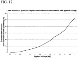
- Results are shown in Fig. 17 .
- the vertical axis is displacement amount in light beam position ( ⁇ m). It will be understood that the light beam position changes in accordance with applied voltage. It should be noted here that a relationship between applied voltage and displacement amount is nonlinear (with this example it is a substantially second order curve) but by obtaining a relationship between the two in advance, and storing this relationship, high precision light beam position control is possible.
- the light beam it is possible to have a laser beam, for example, and in this case a form of use such as controlling position of a UV laser beam used in a 3D printer, for example, using the present invention, is also possible
- electrodes of the power feed section it is also possible to use electrodes formed by vacuum deposition of granulated fine metal on the surface of the main body. Description Of The Reference Numerals
Landscapes
- Physics & Mathematics (AREA)
- General Physics & Mathematics (AREA)
- Optics & Photonics (AREA)
- Nonlinear Science (AREA)
- Engineering & Computer Science (AREA)
- General Engineering & Computer Science (AREA)
- Mechanical Light Control Or Optical Switches (AREA)
Applications Claiming Priority (2)
| Application Number | Priority Date | Filing Date | Title |
|---|---|---|---|
| JP2015202408 | 2015-10-13 | ||
| PCT/JP2016/076149 WO2017064942A1 (fr) | 2015-10-13 | 2016-09-06 | Dispositif de commande de position de faisceau lumineux |
Publications (2)
| Publication Number | Publication Date |
|---|---|
| EP3364227A1 true EP3364227A1 (fr) | 2018-08-22 |
| EP3364227A4 EP3364227A4 (fr) | 2019-06-05 |
Family
ID=58518238
Family Applications (1)
| Application Number | Title | Priority Date | Filing Date |
|---|---|---|---|
| EP16855196.8A Withdrawn EP3364227A4 (fr) | 2015-10-13 | 2016-09-06 | Dispositif de commande de position de faisceau lumineux |
Country Status (5)
| Country | Link |
|---|---|
| US (1) | US20180314058A1 (fr) |
| EP (1) | EP3364227A4 (fr) |
| JP (1) | JPWO2017064942A1 (fr) |
| CN (1) | CN108027504A (fr) |
| WO (1) | WO2017064942A1 (fr) |
Families Citing this family (5)
| Publication number | Priority date | Publication date | Assignee | Title |
|---|---|---|---|---|
| CN108845416B (zh) * | 2018-06-30 | 2023-12-08 | 广州国显科技有限公司 | 光路径调整装置以及显示器件 |
| CN111399213B (zh) * | 2020-03-30 | 2021-02-02 | 北京理工大学 | 基于介电弹性体和液体双驱动的光束偏转器 |
| CN112731651A (zh) * | 2021-01-05 | 2021-04-30 | 南京邮电大学 | 一种具有电控厚度可调的光学调相器 |
| CN114447608B (zh) * | 2022-01-27 | 2026-01-27 | 北京京东方技术开发有限公司 | 波束指向调节结构及调节方法、扫描设备 |
| CN116047835B (zh) * | 2023-03-23 | 2023-09-01 | 荣耀终端有限公司 | 可变光圈、摄像模组及电子设备 |
Family Cites Families (11)
| Publication number | Priority date | Publication date | Assignee | Title |
|---|---|---|---|---|
| JPH10133135A (ja) * | 1996-10-31 | 1998-05-22 | Toshiba Corp | 光ビーム偏向装置 |
| US6882086B2 (en) * | 2001-05-22 | 2005-04-19 | Sri International | Variable stiffness electroactive polymer systems |
| JP4311905B2 (ja) * | 2002-02-05 | 2009-08-12 | オリンパス株式会社 | 光学系 |
| US7209280B2 (en) * | 2002-12-30 | 2007-04-24 | Koninklijke Philips Electronics N.V. | Optical device comprising a polymer actuator |
| DE102004011026A1 (de) * | 2004-03-04 | 2005-09-29 | Siemens Ag | Adaptives optisches Element mit einem Polymeraktor |
| EP1816493A1 (fr) * | 2006-02-07 | 2007-08-08 | ETH Zürich | Réseau de diffraction accordable |
| NO326372B1 (no) * | 2006-09-21 | 2008-11-17 | Polight As | Polymerlinse |
| US8027096B2 (en) * | 2006-12-15 | 2011-09-27 | Hand Held Products, Inc. | Focus module and components with actuator polymer control |
| JP5213761B2 (ja) * | 2009-03-02 | 2013-06-19 | キヤノン株式会社 | 照明光学系及びそれを有する画像投射装置 |
| DE102011079012A1 (de) * | 2011-07-12 | 2013-01-17 | Ledon Oled Lighting Gmbh & Co. Kg | Leuchtmodul mit steuerbarer Lichtlenkung |
| JP5915693B2 (ja) * | 2014-05-12 | 2016-05-11 | セイコーエプソン株式会社 | 光フィルター及び光フィルターモジュール並びに分析機器及び光機器 |
-
2016
- 2016-09-06 US US15/767,988 patent/US20180314058A1/en not_active Abandoned
- 2016-09-06 WO PCT/JP2016/076149 patent/WO2017064942A1/fr not_active Ceased
- 2016-09-06 CN CN201680052948.9A patent/CN108027504A/zh active Pending
- 2016-09-06 EP EP16855196.8A patent/EP3364227A4/fr not_active Withdrawn
- 2016-09-06 JP JP2017545117A patent/JPWO2017064942A1/ja active Pending
Also Published As
| Publication number | Publication date |
|---|---|
| CN108027504A (zh) | 2018-05-11 |
| US20180314058A1 (en) | 2018-11-01 |
| JPWO2017064942A1 (ja) | 2018-08-02 |
| WO2017064942A1 (fr) | 2017-04-20 |
| EP3364227A4 (fr) | 2019-06-05 |
Similar Documents
| Publication | Publication Date | Title |
|---|---|---|
| EP3364227A1 (fr) | Dispositif de commande de position de faisceau lumineux | |
| US10139529B2 (en) | Deformable lens structure for adaptive optics devices | |
| US10788727B2 (en) | Liquid crystal light deflector | |
| US6853476B2 (en) | Charge control circuit for a micro-electromechanical device | |
| FI3646068T3 (fi) | Linssikokoonpano optiseen kuvanvakautukseen ja tarkennuksen säätöön | |
| EP2847559B1 (fr) | Interféromètre fabry-perot et procédé de production de celui-ci | |
| US20040218341A1 (en) | Charge control of micro-electromechanical device | |
| US9287016B2 (en) | Reflective surface shape controllable mirror device, and method for manufacturing reflective surface shape controllable mirror | |
| US10302955B2 (en) | Three-dimensional display system having three-dimensional grating | |
| EP2233966B1 (fr) | Methode pour focaliser ou defocaliser la lumiere en utilisant une lentille a focale variable | |
| JP2009244498A (ja) | 光学フィルタ装置 | |
| US10585330B2 (en) | Liquid crystal light deflector and holographic display having the liquid crystal light deflector | |
| KR102631100B1 (ko) | 광빔을 스티어링하기 위한 하이브리드 빔스티어러 | |
| Windt et al. | Two-dimensional differential deposition: figure correction of thin-shell mirror substrates for x-ray astronomy | |
| EP2239792A1 (fr) | Dispositif de positionnement et son utilisation | |
| US20160178889A1 (en) | Electrowetting display device with stable display states | |
| JP6431990B2 (ja) | 安定な表示状態を有するエレクトロウェッティング表示装置 | |
| EP3086167A1 (fr) | Élément de modulation optique | |
| US20200064524A1 (en) | Circuit for controlling liquid lens | |
| Shi et al. | Multi-axis nanopositioning system for the hard X-ray split-delay system at the LCLS | |
| JP5222256B2 (ja) | 光偏向器 | |
| EP1852674B1 (fr) | Dispositif de mesure destiné à la détermination du déplacement relatif entre deux composants | |
| Goldberg et al. | Controlling cantilevered adaptive X-ray mirrors | |
| WO2024052151A1 (fr) | Procédé de fonctionnement d'un composant optique et composant optique | |
| Cotroneo et al. | Progress in development of adjustable optics for x-ray astronomy |
Legal Events
| Date | Code | Title | Description |
|---|---|---|---|
| STAA | Information on the status of an ep patent application or granted ep patent |
Free format text: STATUS: THE INTERNATIONAL PUBLICATION HAS BEEN MADE |
|
| PUAI | Public reference made under article 153(3) epc to a published international application that has entered the european phase |
Free format text: ORIGINAL CODE: 0009012 |
|
| STAA | Information on the status of an ep patent application or granted ep patent |
Free format text: STATUS: REQUEST FOR EXAMINATION WAS MADE |
|
| 17P | Request for examination filed |
Effective date: 20180315 |
|
| AK | Designated contracting states |
Kind code of ref document: A1 Designated state(s): AL AT BE BG CH CY CZ DE DK EE ES FI FR GB GR HR HU IE IS IT LI LT LU LV MC MK MT NL NO PL PT RO RS SE SI SK SM TR |
|
| AX | Request for extension of the european patent |
Extension state: BA ME |
|
| DAV | Request for validation of the european patent (deleted) | ||
| DAX | Request for extension of the european patent (deleted) | ||
| A4 | Supplementary search report drawn up and despatched |
Effective date: 20190503 |
|
| RIC1 | Information provided on ipc code assigned before grant |
Ipc: G02B 26/10 20060101ALI20190426BHEP Ipc: G02B 26/08 20060101AFI20190426BHEP |
|
| STAA | Information on the status of an ep patent application or granted ep patent |
Free format text: STATUS: THE APPLICATION HAS BEEN WITHDRAWN |
|
| 18W | Application withdrawn |
Effective date: 20190716 |