EP3364232A1 - Architecture de collecte de lumière pour des appareils de combustion - Google Patents
Architecture de collecte de lumière pour des appareils de combustion Download PDFInfo
- Publication number
- EP3364232A1 EP3364232A1 EP17157207.6A EP17157207A EP3364232A1 EP 3364232 A1 EP3364232 A1 EP 3364232A1 EP 17157207 A EP17157207 A EP 17157207A EP 3364232 A1 EP3364232 A1 EP 3364232A1
- Authority
- EP
- European Patent Office
- Prior art keywords
- light
- port
- refraction body
- splitter
- refraction
- Prior art date
- Legal status (The legal status is an assumption and is not a legal conclusion. Google has not performed a legal analysis and makes no representation as to the accuracy of the status listed.)
- Withdrawn
Links
- 238000002485 combustion reaction Methods 0.000 title claims abstract description 37
- 238000001514 detection method Methods 0.000 claims abstract description 56
- 230000003287 optical effect Effects 0.000 claims description 65
- 239000000463 material Substances 0.000 claims description 12
- 238000003780 insertion Methods 0.000 claims description 10
- 230000037431 insertion Effects 0.000 claims description 10
- 230000004044 response Effects 0.000 claims description 6
- 230000001902 propagating effect Effects 0.000 claims description 4
- 238000000034 method Methods 0.000 description 9
- 230000003595 spectral effect Effects 0.000 description 7
- 238000004519 manufacturing process Methods 0.000 description 6
- 238000004891 communication Methods 0.000 description 5
- 239000011521 glass Substances 0.000 description 5
- QVGXLLKOCUKJST-UHFFFAOYSA-N atomic oxygen Chemical compound [O] QVGXLLKOCUKJST-UHFFFAOYSA-N 0.000 description 4
- 238000005457 optimization Methods 0.000 description 4
- 239000001301 oxygen Substances 0.000 description 4
- 229910052760 oxygen Inorganic materials 0.000 description 4
- 230000035945 sensitivity Effects 0.000 description 4
- 230000003750 conditioning effect Effects 0.000 description 3
- 239000002803 fossil fuel Substances 0.000 description 3
- 230000006870 function Effects 0.000 description 3
- 229910052724 xenon Inorganic materials 0.000 description 3
- FHNFHKCVQCLJFQ-UHFFFAOYSA-N xenon atom Chemical compound [Xe] FHNFHKCVQCLJFQ-UHFFFAOYSA-N 0.000 description 3
- 239000011248 coating agent Substances 0.000 description 2
- 238000000576 coating method Methods 0.000 description 2
- 239000007789 gas Substances 0.000 description 2
- 238000002347 injection Methods 0.000 description 2
- 239000007924 injection Substances 0.000 description 2
- WABPQHHGFIMREM-UHFFFAOYSA-N lead(0) Chemical compound [Pb] WABPQHHGFIMREM-UHFFFAOYSA-N 0.000 description 2
- 238000000465 moulding Methods 0.000 description 2
- 230000003071 parasitic effect Effects 0.000 description 2
- 230000005855 radiation Effects 0.000 description 2
- 238000010146 3D printing Methods 0.000 description 1
- XUIMIQQOPSSXEZ-UHFFFAOYSA-N Silicon Chemical compound [Si] XUIMIQQOPSSXEZ-UHFFFAOYSA-N 0.000 description 1
- 238000010521 absorption reaction Methods 0.000 description 1
- 239000000654 additive Substances 0.000 description 1
- 230000000996 additive effect Effects 0.000 description 1
- 230000002411 adverse Effects 0.000 description 1
- 238000004378 air conditioning Methods 0.000 description 1
- 238000004590 computer program Methods 0.000 description 1
- 230000001419 dependent effect Effects 0.000 description 1
- 238000003745 diagnosis Methods 0.000 description 1
- 230000000694 effects Effects 0.000 description 1
- 238000000605 extraction Methods 0.000 description 1
- 230000002068 genetic effect Effects 0.000 description 1
- 238000010438 heat treatment Methods 0.000 description 1
- 238000009434 installation Methods 0.000 description 1
- 238000011031 large-scale manufacturing process Methods 0.000 description 1
- 238000005259 measurement Methods 0.000 description 1
- 238000012986 modification Methods 0.000 description 1
- 230000004048 modification Effects 0.000 description 1
- 239000002245 particle Substances 0.000 description 1
- 238000012545 processing Methods 0.000 description 1
- 229910052710 silicon Inorganic materials 0.000 description 1
- 239000010703 silicon Substances 0.000 description 1
- 238000003860 storage Methods 0.000 description 1
- 238000009423 ventilation Methods 0.000 description 1
Images
Classifications
-
- G—PHYSICS
- G02—OPTICS
- G02B—OPTICAL ELEMENTS, SYSTEMS OR APPARATUS
- G02B27/00—Optical systems or apparatus not provided for by any of the groups G02B1/00 - G02B26/00, G02B30/00
- G02B27/10—Beam splitting or combining systems
- G02B27/14—Beam splitting or combining systems operating by reflection only
- G02B27/144—Beam splitting or combining systems operating by reflection only using partially transparent surfaces without spectral selectivity
-
- F—MECHANICAL ENGINEERING; LIGHTING; HEATING; WEAPONS; BLASTING
- F23—COMBUSTION APPARATUS; COMBUSTION PROCESSES
- F23M—CASINGS, LININGS, WALLS OR DOORS SPECIALLY ADAPTED FOR COMBUSTION CHAMBERS, e.g. FIREBRIDGES; DEVICES FOR DEFLECTING AIR, FLAMES OR COMBUSTION PRODUCTS IN COMBUSTION CHAMBERS; SAFETY ARRANGEMENTS SPECIALLY ADAPTED FOR COMBUSTION APPARATUS; DETAILS OF COMBUSTION CHAMBERS, NOT OTHERWISE PROVIDED FOR
- F23M11/00—Safety arrangements
- F23M11/04—Means for supervising combustion, e.g. windows
- F23M11/042—Viewing ports of windows
-
- F—MECHANICAL ENGINEERING; LIGHTING; HEATING; WEAPONS; BLASTING
- F23—COMBUSTION APPARATUS; COMBUSTION PROCESSES
- F23M—CASINGS, LININGS, WALLS OR DOORS SPECIALLY ADAPTED FOR COMBUSTION CHAMBERS, e.g. FIREBRIDGES; DEVICES FOR DEFLECTING AIR, FLAMES OR COMBUSTION PRODUCTS IN COMBUSTION CHAMBERS; SAFETY ARRANGEMENTS SPECIALLY ADAPTED FOR COMBUSTION APPARATUS; DETAILS OF COMBUSTION CHAMBERS, NOT OTHERWISE PROVIDED FOR
- F23M11/00—Safety arrangements
- F23M11/04—Means for supervising combustion, e.g. windows
- F23M11/045—Means for supervising combustion, e.g. windows by observing the flame
-
- F—MECHANICAL ENGINEERING; LIGHTING; HEATING; WEAPONS; BLASTING
- F23—COMBUSTION APPARATUS; COMBUSTION PROCESSES
- F23N—REGULATING OR CONTROLLING COMBUSTION
- F23N5/00—Systems for controlling combustion
- F23N5/02—Systems for controlling combustion using devices responsive to thermal changes or to thermal expansion of a medium
- F23N5/08—Systems for controlling combustion using devices responsive to thermal changes or to thermal expansion of a medium using light-sensitive elements
- F23N5/082—Systems for controlling combustion using devices responsive to thermal changes or to thermal expansion of a medium using light-sensitive elements using electronic means
-
- G—PHYSICS
- G02—OPTICS
- G02B—OPTICAL ELEMENTS, SYSTEMS OR APPARATUS
- G02B27/00—Optical systems or apparatus not provided for by any of the groups G02B1/00 - G02B26/00, G02B30/00
- G02B27/10—Beam splitting or combining systems
- G02B27/108—Beam splitting or combining systems for sampling a portion of a beam or combining a small beam in a larger one, e.g. wherein the area ratio or power ratio of the divided beams significantly differs from unity, without spectral selectivity
Definitions
- the instant disclosure generally relates to an architecture collecting visible light from a combustion appliance. More particularly, the instant disclosure relates to an optical circuit that collects light from a combustion appliance at a sensor.
- Combustion appliances for fossil fuels such as gas burners generally rely on optical sensors that detect the presence of a flame. Signals obtained from these optical sensors are processed to ensure safe operation of the appliance.
- Optical sensors suitable for flame detection need to meet a plethora of conflicting technical requirements. They need to exhibit low dark currents in order that false alarms are avoided. Suitable sensors also need be sensitive enough to detect low levels of incident light such as 0.5 Lux. In other words, the sensors and their detection circuits are required to exhibit optimum signal-to-noise ratios. The additional requirement of low-cost sensors further exacerbates the issue.
- US5923809A optical power source derived from engine combustion chambers, was published on 13 July 1999.
- the specification discloses a combustion chamber 12 with a transparent section 12A.
- a plurality of optical fibres 28 connects to the transparent section 12A and collects light from the combustion chamber 12.
- the fibres 28 are then bundled in a cable 16 that serves as an extraction means.
- FIG 4 of US5923809A shows that light from the cable 16 enters a beam splitter 44.
- Beam splitter 44 supplies a first path with an optical converter 46 and a second path with an optical conditioning network 48.
- US5923809A does not teach an arrangement with a beam-splitter that collects light from different locations at a single location.
- the patent specification US4412445 optical combustion sensor, particularly for use with internal combustion engines, was published on 1 November 1983.
- the specification discloses a mushroom-shaped head 14 arranged inside a combustion chamber of an engine. Mushroom-shaped head 14 collects light from inside the combustion chamber 10.
- a glass body 13 connects to the mushroom-shaped head 14 and transmits the light collected by head 14 to an opto-electrical transducer 9a.
- US4412445 does not teach collection of light from separate optical paths at the location of a single sensor member.
- FIG 10 and FIG 11 of the specification show details of an arrangement for measurement of exposure to oxygen.
- a microcomputer 234 triggers a xenon flash 276.
- a sensor 270 absorbs light from xenon flash 276 and becomes absorptive in the 550 to 750 nm range. Sensor 270 thus returns less light from an LED 242.
- a first portion of light is transmitted through a beam-splitter 254 before reaching a photodiode 256.
- a second portion of light is reflected by the same beam-splitter 254 before reaching another photodiode 258.
- beam-splitter 254 being dichroic
- light originating from xenon flash 276 gets reflected toward photodiode 258 whilst light received from sensor 270 gets transmitted toward photodiode 256. Since absorption by sensor 270 is a function of exposure to oxygen, the signal obtained from photodiode 256 is a measure thereof.
- the optical assembly shown on FIG 11 requires two separate photodiodes 256, 258 to perform its function. Also, a dichroic beam-splitter 254 or a filter 260 is required in order that the assembly measures exposure to oxygen.
- the present disclosure teaches an optical circuit for flame detection that collects light at a single location.
- the instant disclosure focuses on a circuit for use in combustion appliances for fossil fuels.
- the present disclosure provides a method and / or an assembly and / or an optical circuit for flame detection in a combustion appliance.
- a refraction member is employed that is sensitive to light along a first axis and along a second axis with the second axis being different from the first axis.
- a beam-splitter inside the refraction member transmits light received along either axis in the direction of a sensor member.
- the arrangement effectively establishes two optical paths that both terminate at the same sensor member. The first of these paths collects light received by the refraction body along the first axis. The second path collects light received by the refraction member along a second axis.
- Effective use is made of a sensor member since light originating from inside a combustion chamber reaches the same sensor member.
- the assembly produces a photocurrent when it receives light.
- the instant disclosure allows configuration of optical path, thereby allowing connections to the sensor member from a plurality of directions. It is an object of the instant disclosure to provide a versatile method and / or a versatile assembly and / or a versatile optical circuit for flame detection that alleviates constraints due to limited space in the controller apparatus.
- a sensor member such as a photodiode comprises the filter member.
- the sensor member comprises a photodiode, preferably a photodiode sensitive to visible light in the range between 400 nm to 800 nm.
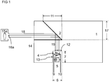
- FIG 1 depicts a refraction body 1 with a beam-splitter 2.
- Beam-splitter 2 is advantageously fully contained inside refraction body 1.
- Beam-splitter 2 ideally is not dichroic in the range of visible light between 400 nm to 800 nm.
- Refraction body 1 is preferably made of a (transparent) material with a refraction index n > 1.0003 in the range of visible light between 400 nm and 800 nm.
- beam-splitter 2 comprises a prism and / or a prism assembly. According to another aspect, beam-splitter 2 comprises a surface with an optical coating, in particular a surface with a metallic coating.
- refraction body 1 is substantially non-transparent at infrared wavelengths of more than 1200 nm, more preferably more than 1000 nm, yet more preferably more than 800 nm.
- a refraction body 1 that absorbs infrared light inhibits reception of infrared light by sensor member 3, thereby improving on signal-to-noise ratio. It is envisaged that refraction body 1 is made of a material with an attenuation length at optical wavelengths of 800 nm of 1 mm, preferably of 0.1 mm, still more preferably of 0.01 mm.
- refraction body 1 is made of a material with an attenuation length at optical wavelengths of 1000 nm of 1 mm, preferably of 0.1 mm, still more preferably of 0.01 mm. It is still envisaged that refraction body 1 is made of a material with an attenuation length at optical wavelengths of 1200 nm of 1 mm, preferably of 0.1 mm, still more preferably of 0.01 mm.
- manufacture of refraction body 1 involves (injection) moulding. According to another aspect, manufacture of refraction body 1 involves additive manufacturing such as three-dimensional printing.
- Refraction body 1 provides a port 4.
- Port 4 provides an opening and / or an orifice and / or an aperture that allows for insertion of a detection circuit 5 into refraction body 1.
- Detection circuit 5 provides a sensor member 3 sensitive to visible light.
- Sensor member 3 advantageously comprises a photodiode.
- port 4 comprises a slot with a diameter dimension 6 and with a depth dimension 7.
- Depth dimension 7 of port 4 is at least as large as diameter dimension 6 of port 4. More preferably depth 7 of port 4 is twice its diameter 6, yet more preferably depth 7 of port 4 is five times its diameter 6.
- Detection circuit 5 comes with suitable dimensions that enable (complete) insertion of detection circuit 5 in port 4.
- port 4 comprises a recess with a diameter dimension 6 and with a depth dimension 7.
- Depth dimension 7 of port 4 is at least as large as diameter dimension 6 of port 4. More preferably depth 7 of port 4 is twice its diameter 6, yet more preferably depth 7 of port 4 is five times its diameter 6.
- Detection circuit 5 comes with suitable dimensions that enable (complete) insertion of detection circuit 5 in port 4.
- port 4 comprises a bore with a diameter dimension 6 and with a depth dimension 7.
- Depth dimension 7 of port 4 is at least as large as diameter dimension 6 of port 4. More preferably depth 7 of port 4 is twice its diameter 6, yet more preferably depth 7 of port 4 is five times its diameter 6.
- Detection circuit 5 comes with suitable dimensions that enable (complete) insertion of detection circuit 5 in port 4.
- sensor member 3 is flush mounted to the end wall 12 of port 4.
- End wall 12 of port 4 terminates port 4.
- end wall 12 comprises an end plate.
- End wall 12 of port 4 is advantageously perpendicular or substantially perpendicular to a side wall 13 of port 4.
- side wall 13 comprises a guide runner.
- port 4 comprises at least two parallel guide runners. These guide runners are advantageously arranged along opposite walls of port 4.
- detection circuit 5 is an electric circuit arranged on a (printed) circuit board.
- detection circuit 5 also comprises a signal conditioning member 8.
- Signal conditioning member 8 may, by way of non-limiting example, comprise an (operational) amplifier.
- the (operational) amplifier advantageously comes as an integrated circuit.
- Detection circuit 5 may, by way of another non-limiting example, also comprise lead wires 9, 10.
- detection circuit 5 has a dimension that exceeds the depth dimension of port 4. Detection circuit 5 can thus not be fully inserted in port 4. That is, parts of detection circuit 5 such as lead wires 9, 10 or wiring terminals 9, 10 may stand proud of an outer surface of refraction body 1.
- port 4 and detection circuit 5 provide suitable fixation members for mounting detection circuit 5 to port 4.
- suitable fixation members comprise nuts, bolts, plugs etc. This list of suitable fixation members is not exhaustive.
- Beam-splitter 2 has a lateral dimension 11 that is parallel to diameter dimension 6 of port 4. Lateral dimension 2 of beam-splitter 11 ideally exceeds diameter 6. In an alternate embodiment, lateral dimension 11 of beam-splitter 2 is at least 90% of diameter dimension 6. In yet another embodiment, lateral dimension 11 of beam-splitter 2 is at least 70% of diameter dimension 6.
- Lateral dimension 11 can be projected in a direction parallel to side-wall 13 of port 4 on end-wall 12 of port 4. It is envisaged that this projection covers all of the area of the end-wall 12 of port 4. In an alternate embodiment, the projection of lateral dimension 11 on the end-wall 12 of port 4 covers at least 90% of the area of end-wall 12. In yet another embodiment, the projection of lateral dimension 11 on the end-wall 12 of port 4 covers at least 40% or at least 50% of the area of end-wall 12.
- photodiode is a silicon diode. It is desirable for purposes of flame detection that photodiode exhibits a low value of parasitic parallel resistivity. A photocurrent produced by diode may otherwise be consumed by the parasitic parallel resistivity of photodiode.
- the temperature coefficient TC 1 of the short-circuit current I SC (at 25 degrees Celsius) is preferably less than 0.5%/Kelvin, even more preferred less than 0.3%/Kelvin, yet more preferred less than 0.%/Kelvin or even 0.04%/Kelvin.
- photodiode ought to exhibit a spectral sensitivity ⁇ 0% that matches and / or overlaps with the signal obtained from a flame in a combustion appliance.
- photodiode exhibits a spectral sensitivity ⁇ 0% between 200 nm and 800 nm, yet more preferred between 300 nm and 800 nm, even more preferred between 400 nm and 800 nm.
- photodiode exhibits a spectral sensitivity at infrared wavelengths such as 800 nm that is less than 20%, preferably less than 0%, the sensitivity at 600 nm wavelength.
- Photodiode may, in a particular embodiment, be a type VEMD550 and / or a SFH2240 device. According to an aspect, photodiode is implemented as a surface-mounted device (SMD). Surface-mounted devices allow low cost manufacture at large scale. Surface-mounted device also allow miniaturized circuits. Photodiode ideally withstands elevated temperatures inside a combustion appliance, in particular elevated temperatures inside or near a burner chamber of a combustion appliance.
- SMD surface-mounted device
- Refraction body 1 as shown on FIG 1 provides a first outer surface 14.
- First outer surface 14 of refraction body 1 is configured to receive a first light signal such as a first light beam and / or a first ray of light from a first light source 15a.
- FIG 1 depicts a first arrangement of refraction body 1 and a first light source 15a.
- the light signal received by the first outer surface 14 advantageously is a light signal with (principal) spectral components in the range of visible light between 400 nm and 800 nm.
- the light source 15a advantageously is a combustion chamber with an aperture 16a and / or with a window 16a and / or with a lens 16a and / or with a mushroom-shaped glass body 16a. It is also envisaged that window 16a and / or mushroom-shaped glass body 16a connects to first outer surface 14 of refraction body 1 via a fibre-optic cable.
- a beam of light 18 originating from first light source 15a and incident on surface 14 is bent. That beam will bend toward an angle normal to first outer surface 14, if the refraction index of body 1 exceeds that between surface 14 and source 15a.
- a beam of light arrives at a first angle ⁇ 1 to a normal to first outer surface 14.
- the same beam of light is transmitted toward beam-splitter 2 at a second angle ⁇ 2 to a normal to surface 14 with ⁇ 2 less than or equal to ⁇ 1 .
- beam-splitter 2 reflects a 30% portion of (the intensity of) light beam 18 received from first outer surface 14. In another particular embodiment, beam-splitter 2 reflects a 50% portion of (the intensity of) light beam 18 received from first outer surface 14. In yet another particular embodiment, beam-splitter 2 reflects a 70% or a 90% portion of (the intensity of) light beam 18 received from first outer surface 14. The aforementioned portions of reflected intensities refer to visible light in the range between 400 nm and 800 nm. The aforementioned list of particular embodiments is not exhaustive.
- Beam-splitter 2 has a lateral dimension 17 parallel to first outer surface 14.
- the area of first outer surface 14 advantageously fully comprises a projection of lateral dimension 17 on first outer surface 14 in a direction normal to outer surface 14.
- the area of first outer surface 14 contains 90% of this projection.
- the area of first outer surface 14 comprises 70% of this projection. It is envisaged that first outer surface 14 is flat or substantially flat. It is also envisaged that first outer surface 14 is arcuate or substantially arcuate.
- Refraction body 1 then transmits the reflected portion 19 of light beam 18 toward port 4. Reflected portion 19 of light beam 18 is advantageously transmitted toward end wall 12 of port 4. Eventually, end wall 12 of port 4 receives a reflected portion 19 of first light beam 18. It is envisaged that sensor member 3 is flush mounted to end wall 12. Reflected portion 19 of first light beam 18 is thus received by sensor member 3. It is also envisaged that sensor member 3 is disposed at a distance from end wall 12. Accordingly, reflected portion 19 of first light beam 18 is refracted at end wall 12 before it is received by sensor member 3.
- first optical path 18, 19 originating from first light source 15a through aperture 16a that involves first outer surface 14.
- the same optical path 18, 19 also passes through a portion of refraction body 1 and involves beam-splitter 2 as well as end wall 12 of port 4.
- First optical path 18, 2, 19 terminates at sensor member 3.
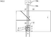
- Refraction body 1 as shown on FIG 2 also provides a second outer surface 20.
- Second outer surface 20 of refraction body 1 is configured to receive a second light signal such as a second light beam and / or a second ray of light from a light source 15b.
- FIG 2 depicts an arrangement of refraction body 1 and a second light source 15b. The arrangement of FIG 2 differs from the arrangement of FIG 1 .
- the arrangement of second source 15b relative to body 1 on FIG 1 is different from the arrangement of first source 15a relative to body 1 on FIG 2 .
- surface areas 14 and 20 do not overlap. That is, the area of overlap between surfaces 14 and 20 is zero. Surface areas 14 and 20 are thus free from overlap. In other words, first surface area 14 is distinct from second surface area 20.
- the light signal received by the second outer surface 20 advantageously is a light signal with (principal) spectral components in the range of visible light between 400 nm and 800 nm.
- the second light source 15b advantageously is a combustion chamber with an aperture 16b and / or with a window 16b and / or with a lens 16b and / or with a mushroom-shaped glass body 16b. It is also envisaged that window 16b and / or mushroom-shaped glass body 16b connects to second outer surface 20 of refraction body 1 via a fibre-optic cable.
- a beam of light 21 originating from second light source 15b and incident on surface 20 is bent. That beam will bend toward an angle normal to second outer surface 20, if the refraction index of body 1 exceeds that between surface 20 and source 15b.
- a beam of light arrives at a third angle ⁇ 3 to a normal to second outer surface 20.
- the same beam of light is transmitted toward beam-splitter 2 at a fourth angle ⁇ 4 to a normal to surface 20 with ⁇ 3 less than or equal to ⁇ 4 .
- beam-splitter 2 transmits a 30% portion of (the intensity of) light beam 21 received from second outer surface 20. In another particular embodiment, beam-splitter 2 transmits a 50% portion of (the intensity of) light beam 21 received from second outer surface 20. In yet another particular embodiment, beam-splitter 2 transmits a 70% or a 90% portion of (the intensity of) light beam 21 received from second outer surface 20.
- the aforementioned portions of reflected intensities refer to visible light in the range between 400 nm and 800 nm. The aforementioned list of particular embodiments is not exhaustive.
- Beam-splitter 2 has a lateral dimension 11 parallel to second outer surface area 20.
- the area of second outer surface 20 advantageously fully comprises a projection of lateral dimension 11 on second outer surface 20 in a direction normal to outer surface 20.
- the area of second outer surface 20 contains 90% of this projection.
- the area of second outer surface 20 comprises 70% of this projection. It is envisaged that second outer surface 20 is flat or substantially flat. It is also envisaged that second outer surface 20 is arcuate or substantially arcuate.
- Refraction body 1 then transmits transmitted portion 22 of light beam 21 toward port 4.
- Transmitted portion 22 of light beam 21 is advantageously transmitted toward end wall 12 of port 4.
- end wall 12 of port 4 receives a transmitted portion 22 of second light beam 21.
- sensor member 3 is flush mounted to end wall 12.
- Transmitted portion 22 of second light beam 21 is thus received by sensor member 3.
- sensor member 3 is disposed at a distance from end wall 12. Accordingly, transmitted portion 22 of first light beam 20 is refracted at end wall 12 before it is received by sensor member 3.
- Second optical path 21, 22 originating from second light source 15b through aperture 16b that involves second outer surface 20.
- the same optical path 21, 22 also passes through a portion of refraction body 1 and involves beam-splitter 2 as well as end wall 12 of port 4.
- Second optical path 21, 22 terminates at sensor member 3.
- Combustion appliance may, by way of non-limiting example, be a combustion engine, a cogeneration plant, a gas turbine, an appliance for heating, ventilation, air-conditioning and / or a gas-fired and / or an oil-fired burner.
- Combustion appliance may, by way of another non-limiting example, be a gas-fired and / or an oil-fired installation with a boiler.
- an optics actuator such as a stepper motor may alter the position of refraction body 1.
- an actuator mechanically couples to refraction body 1.
- actuator may pivot refraction body 1 inside a combustion apparatus.
- a circuit controller sets the position of the aforementioned actuator. That is, combustion appliance comprises a circuit controller that adjusts the orientation of refraction body 1 through the actuator. Ideally, controller and actuator pivot refraction body 1 together with detection circuit 5 and / or with sensor member 3, since these members 3, 5 are mounted to refraction body 1.
- circuit controller also receives signals from sensor member 3. Ideally, controller receives signals from sensor member 3 via detection circuit 5. To that end, controller (uni-directionally or bidirectionally) communicates with detection circuit 5. Controller is preferably configured to optimize the signal-to-noise ratio of the signal from sensor member 3 by pivotal movement of refraction body 1. Controller may, by way of non-limiting example, employ proportional, integral, and / or derivative control to adjust and / or optimize the orientation of refraction body 1 in a step-wise manner. Circuit controller may, by way of another non-limiting example, perform functional checks and / or diagnosis of the assembly comprising sensor member 3 and actuator.
- Controller may also comprise a communication port with a suitable communication protocol.
- Communication port of controller may, by way of non-limiting example, connect to a I2C bus.
- Communication port of controller may, by way of non-limiting example, connect to an ethernet bus, in particular to an ethernet bus providing power-over-ethernet.
- controller may receive data and / or instructions from a system controller such as a combustion appliance controller. Instructions and / or data received from system controller include, but are not limited to, instructions and / or data for a stepper-motor to position refraction body 1.
- Circuit controller may as well transmit data to a system controller such as combustion appliance controller.
- Data transmitted to a system controller include, but are not limited to, position information related to an actuator, signal-to-noise ratios related to sensor member 3, signal strength and / or dark current in relation to sensor member 3 etc.
- a system controller performs (proportional, integral and / or derivative) optimization together with circuit controller (installed as part of detection circuit 5).
- circuit controller sends signals obtained from sensor member 3 via its communication port and through a bus connection to a system controller.
- System controller processes data received from circuit controller and generates an actual signal.
- the generated actual signal preferably relates to signal strength and / or signal-to-noise ratio of sensor member 3.
- System controller then employs an optimization algorithm to generate a control signal.
- the control signal is sent to circuit controller, which (via actuator) pivots refraction body 1 accordingly.
- System controller and circuit controller iterate these steps until an optimum orientation of refraction body 1 is found.
- Suitable optimization algorithms include, but are not limited to, genetic optimization algorithms and / or gradient descent algorithms.
- the instant disclosure teaches a refraction body 1 for a combustion appliance, the refraction body 1 comprising:
- the port 4 is configured to receive the first reflected portion 19 of light and to refract the first reflected portion 19 of light such that the first reflected portion 19 of light is transmitted through the port 4 to a detection circuit 5 inserted and / or introduced into the port 4.
- an end wall 12 of port 4 receives and refracts the first reflected portion 19 of light.
- port 4 is configured for partial insertion and / or partial introduction of a detection circuit 5.
- port 4 is configured for complete insertion and / or complete introduction of a detection circuit 5,
- the port 4 is configured to receive the second transmitted portion 22 of light and to refract the second transmitted portion 22 of light such that the second transmitted portion 22 of light is transmitted through the port 4 to a detection circuit 5 inserted and / or introduced into the port 4.
- an end wall 12 of port 4 receives and refracts the second transmitted portion 22 of light.
- the first light signal advantageously has (relevant spectral components) with optical wavelengths between 400 nm and 800 nm.
- the second light signal advantageously has (relevant spectral components) with optical wavelengths between 400 nm and 800 nm.
- the refraction body 1 ideally has a maximum outer dimension of less than 100 mm, more ideally of less than 50 mm, yet more ideally of less than 20 mm.
- the maximum outer dimension of the refraction body 1 is the longest distance between any two points along a surface enveloping the refraction body 1.
- the instant disclosure also teaches one of the aforementioned refraction bodies 1, wherein the first optical path 18, 2, 19 and the second optical path 21, 2, 22 both comprise the same beam-splitter 2.
- the instant disclosure also teaches one of the aforementioned refraction bodies 1, wherein the first light signal is a first light beam and the second light signal is a second light beam and wherein the first reflected portion of light 19 is a first reflected portion of the first light beam and the second transmitted portion of light 22 is a second transmitted portion of the second light beam.
- the instant disclosure also teaches one of the aforementioned refraction bodies 1, wherein the port 4 comprises (or is) a slot and / or a recess and / or a depression with an aperture for insertion of a detection circuit 5, with an end wall 12 and with a depth dimension 7 from the aperture to the end wall 12, the aperture having a diameter dimension 6,
- the port 4 extends into the refraction body 1 by the depth dimension 7.
- the depth dimension 7 is at least twice the diameter dimension 6 of the aperture. According to another aspect, the depth dimension 7 is at least five times the diameter dimension 6 of the aperture.
- the diameter dimension 6 of the aperture is at least 0.5 mm, yet more preferred at least 1 mm, still more preferred 2mm.
- the depth dimension 7 of the port 4 is at least 2.5 mm, yet more preferred at least 5 mm, still more at least preferred 10mm.
- the instant disclosure also teaches one of the aforementioned refraction bodies 1, wherein the depth dimension 7 is perpendicular or substantially perpendicular to the diameter dimension 6 of the aperture.
- the instant disclosure also teaches one of the aforementioned refraction bodies 1, wherein the depth dimension 7 starts at a point on the aperture and ends at a point on the end wall 12.
- the instant disclosure also teaches one of the aforementioned refraction bodies 1, wherein the end wall 12 comprises or is an end plate.
- the aperture of the port 4 comprises an outer rim.
- the diameter dimension 6 is the largest distance between any two points on that rim.
- the instant disclosure also teaches one of the aforementioned refraction bodies 1, wherein the refraction body 1 comprises a detection circuit 5 inserted and / or introduced into the port 4.
- the instant disclosure also teaches one of the aforementioned refraction bodies 1, wherein the refraction body 1 comprises a detection circuit 5 partially inserted and / or partially introduced into the port 4.
- the instant disclosure also teaches one of the aforementioned refraction bodies 1, wherein the detection circuit 5 comprises a sensor element 3,
- the instant disclosure also teaches one of the aforementioned refraction bodies 1, wherein the port 4 comprises at least a wall with a surface area,
- the instant disclosure also teaches one of the aforementioned refraction bodies 1, wherein the sensor element 3 is arranged inside the port 4 such that the port 4 is configured to transmit the first reflected portion 19 of light to the sensor element 3 of the detection circuit 5 and
- the instant disclosure also teaches one of the aforementioned refraction bodies 1, wherein the sensor element 3 is arranged inside the port 4 such that port 4 is configured to transmit the second transmitted portion 22 of light to the sensor element 3 of the detection circuit 5 and
- the instant disclosure also teaches one of the aforementioned refraction bodies 1, wherein the refraction body 1 is made of a material with an attenuation length of less than 1 mm at an optical wavelength of 800 nm.
- the instant disclosure also teaches one of the aforementioned refraction bodies 1, wherein the refraction body 1 is made of a material with an attenuation length of more than 1 mm, yet more preferred more than 2 mm, still more preferred more than 5 mm at an optical wavelength of 600 nm.
- the instant disclosure also teaches one of the aforementioned refraction bodies 1, wherein the refraction body 1 comprises a filter element for attenuation of infrared light, wherein the filter element is made of a material with an attenuation length of less than 1 mm, preferably less than 0.1 mm, yet more preferably less than 0.01 mm at an optical wavelength of 800 nm.
- the instant disclosure also teaches one of the aforementioned refraction bodies 1, wherein the refraction body 1 comprises a filter element for attenuation of infrared light, wherein the filter element is made of a material with an attenuation length of less than 1 mm, preferably less than 0.1 mm, yet more preferably less than 0.01 mm at an optical wavelength of 1000 nm.
- the instant disclosure also teaches one of the aforementioned refraction bodies 1, wherein the refraction body 1 comprises a filter element for attenuation of infrared light, wherein the filter element is made of a material with an attenuation length of less than 1 mm, preferably less than 0.1 mm, yet more preferably less than 0.01 mm at an optical wavelength of 1200 nm.
- an attenuation length is the distance into the respective material when the probability has dropped to 1/e that a light particle has not been absorbed.
- the instant disclosure also teaches one of the aforementioned refraction bodies 1, wherein the filter element is arranged in the first optical path and in the second optical path such that the filter element is configured to absorb or to substantially absorb light signals propagating along the first optical path 18, 2, 19 with optical wave lengths above 800 nm, preferably above 1000 nm, yet more preferably above 1200 nm, and is configured to absorb or to substantially absorb light signals propagating along the second optical path 21, 2, 22 with optical wave lengths above 800 nm, preferably above 1000 nm, yet more preferably above 1200 nm.
- the instant disclosure also teaches one of the aforementioned refraction bodies 1, wherein the filter element has a maximum outer dimension that is less than half, ideally less than a fifth, yet more ideally less than a tenth, of the maximum outer dimension of the refraction body (1).
- the maximum outer dimension of the filter element is the longest distance between any two points along a surface enveloping the filter element.
- any steps of a method according to the present application may be embodied in hardware, in a software module executed by a processor, in a cloud computing arrangement, or in a combination thereof.
- the software may include a firmware, a hardware driver run in the operating system, or an application program.
- the invention also relates to a computer program product for performing the operations presented herein. If implemented in software, the functions described may be stored as one or more instructions on a computer-readable medium. Some examples of storage media that may be used include random access memory (RAM), read only memory (ROM), flash memory, EPROM memory, EEPROM memory, registers, a hard disk, a removable disk, other optical disks, or any available media that can be accessed by a computer or any other IT equipment and appliance.
- RAM random access memory
- ROM read only memory
- flash memory EPROM memory
- EEPROM memory electrically erasable programmable read-only memory
- registers a hard disk, a removable disk, other optical disks, or any available media that can be accessed
Landscapes
- Engineering & Computer Science (AREA)
- Physics & Mathematics (AREA)
- Chemical & Material Sciences (AREA)
- Combustion & Propulsion (AREA)
- Mechanical Engineering (AREA)
- General Engineering & Computer Science (AREA)
- Spectroscopy & Molecular Physics (AREA)
- General Physics & Mathematics (AREA)
- Optics & Photonics (AREA)
- Investigating Or Analysing Materials By Optical Means (AREA)
Priority Applications (1)
| Application Number | Priority Date | Filing Date | Title |
|---|---|---|---|
| EP17157207.6A EP3364232A1 (fr) | 2017-02-21 | 2017-02-21 | Architecture de collecte de lumière pour des appareils de combustion |
Applications Claiming Priority (1)
| Application Number | Priority Date | Filing Date | Title |
|---|---|---|---|
| EP17157207.6A EP3364232A1 (fr) | 2017-02-21 | 2017-02-21 | Architecture de collecte de lumière pour des appareils de combustion |
Publications (1)
| Publication Number | Publication Date |
|---|---|
| EP3364232A1 true EP3364232A1 (fr) | 2018-08-22 |
Family
ID=58428039
Family Applications (1)
| Application Number | Title | Priority Date | Filing Date |
|---|---|---|---|
| EP17157207.6A Withdrawn EP3364232A1 (fr) | 2017-02-21 | 2017-02-21 | Architecture de collecte de lumière pour des appareils de combustion |
Country Status (1)
| Country | Link |
|---|---|
| EP (1) | EP3364232A1 (fr) |
Citations (9)
| Publication number | Priority date | Publication date | Assignee | Title |
|---|---|---|---|---|
| US4412445A (en) | 1981-08-27 | 1983-11-01 | Optimetrics, Inc. | Resonant spectrophone system noise elimination |
| US5039491A (en) | 1989-01-27 | 1991-08-13 | Metricor, Inc. | Optical oxygen sensor |
| US5923809A (en) | 1998-02-02 | 1999-07-13 | The United States Of America As Represented By The Administrator Of The National Aeronautics And Space Administration | Optical power source derived from engine combustion chambers |
| WO2000031578A1 (fr) * | 1998-11-25 | 2000-06-02 | Advanced Laser Technologies, Inc. | Melangeur de faisceaux lumineux |
| US20030057373A1 (en) * | 2001-08-21 | 2003-03-27 | Spx Corporation | Optical path structure for open path emissions sensing with spinning filter wheel |
| EP1772096A2 (fr) * | 2005-10-07 | 2007-04-11 | Karl Storz Endovision, Inc. | Système de securité et de contrôle pour une source lumineuse d'un endoscope comprenant un capteur optique |
| WO2008129552A1 (fr) * | 2007-04-19 | 2008-10-30 | Dvp Technologies Ltd. | Système et procédé de prise d'image destinés à la surveillance d'un champ de regard |
| US20130286390A1 (en) * | 2012-04-30 | 2013-10-31 | Agilent Technologies, Inc. | Optical emission system including dichroic beam combiner |
| US20150168817A1 (en) * | 2013-12-12 | 2015-06-18 | Corning Incorporated | Light multiplexer with color combining element |
-
2017
- 2017-02-21 EP EP17157207.6A patent/EP3364232A1/fr not_active Withdrawn
Patent Citations (9)
| Publication number | Priority date | Publication date | Assignee | Title |
|---|---|---|---|---|
| US4412445A (en) | 1981-08-27 | 1983-11-01 | Optimetrics, Inc. | Resonant spectrophone system noise elimination |
| US5039491A (en) | 1989-01-27 | 1991-08-13 | Metricor, Inc. | Optical oxygen sensor |
| US5923809A (en) | 1998-02-02 | 1999-07-13 | The United States Of America As Represented By The Administrator Of The National Aeronautics And Space Administration | Optical power source derived from engine combustion chambers |
| WO2000031578A1 (fr) * | 1998-11-25 | 2000-06-02 | Advanced Laser Technologies, Inc. | Melangeur de faisceaux lumineux |
| US20030057373A1 (en) * | 2001-08-21 | 2003-03-27 | Spx Corporation | Optical path structure for open path emissions sensing with spinning filter wheel |
| EP1772096A2 (fr) * | 2005-10-07 | 2007-04-11 | Karl Storz Endovision, Inc. | Système de securité et de contrôle pour une source lumineuse d'un endoscope comprenant un capteur optique |
| WO2008129552A1 (fr) * | 2007-04-19 | 2008-10-30 | Dvp Technologies Ltd. | Système et procédé de prise d'image destinés à la surveillance d'un champ de regard |
| US20130286390A1 (en) * | 2012-04-30 | 2013-10-31 | Agilent Technologies, Inc. | Optical emission system including dichroic beam combiner |
| US20150168817A1 (en) * | 2013-12-12 | 2015-06-18 | Corning Incorporated | Light multiplexer with color combining element |
Similar Documents
| Publication | Publication Date | Title |
|---|---|---|
| JP5839436B2 (ja) | 光学センサ | |
| CN105229712B (zh) | 具有用于探测明火以及确定环境温度的非接触式热辐射传感器的危险探测器 | |
| JP2012066806A (ja) | 状態変数を取得するためのセンサー・アレンジメント | |
| CN102147297A (zh) | 一种分布式光纤温度传感测量装置和方法 | |
| CN105103205A (zh) | 具有用于确立环境温度的非接触式热辐射传感器的危险探测器 | |
| US11346689B2 (en) | Optical measuring system with an interrogator and a polymer-based single-mode fibre-optic sensor system | |
| CN201909686U (zh) | 一种分布式光纤温度传感测量装置 | |
| US8901479B2 (en) | Sensor assembly for fluid detection and discrimination | |
| CN105392411B (zh) | 管状系统 | |
| EP3364232A1 (fr) | Architecture de collecte de lumière pour des appareils de combustion | |
| CN110637225A (zh) | 光学传感器 | |
| US9395251B2 (en) | Temperature sensitive body, optical temperature sensor, temperature measurement device, and heat flux measurement | |
| JP2007033449A (ja) | 力を測定するための装置およびシステム | |
| JP2935678B2 (ja) | 一体型の光電子式燃焼圧力センサ | |
| JP6736042B2 (ja) | Fbg温度センサ | |
| US9188528B2 (en) | Sensor for monitoring a medium | |
| WO2020125305A1 (fr) | Capteur de température et de vibration intégré connecté en série utilisant un réseau blazé et une fibre optique à réseau de bragg sur fibre | |
| US8084731B2 (en) | Sensor system for liquid detection with lens component having an apex | |
| CN111365730B (zh) | 火焰检测器 | |
| JP2006071549A (ja) | 温度センサ | |
| CN210441992U (zh) | 一种防干扰的测温装置 | |
| JP5284668B2 (ja) | 光学式パイロメータ | |
| KR102889006B1 (ko) | 변압기 절연유 열화 진단을 위한 광섬유 센서 | |
| KR101175343B1 (ko) | 반사형 광온도센서 | |
| RU2848664C1 (ru) | Оптоволоконный датчик распределенной температуры и способ его применения |
Legal Events
| Date | Code | Title | Description |
|---|---|---|---|
| PUAI | Public reference made under article 153(3) epc to a published international application that has entered the european phase |
Free format text: ORIGINAL CODE: 0009012 |
|
| STAA | Information on the status of an ep patent application or granted ep patent |
Free format text: STATUS: THE APPLICATION HAS BEEN PUBLISHED |
|
| AK | Designated contracting states |
Kind code of ref document: A1 Designated state(s): AL AT BE BG CH CY CZ DE DK EE ES FI FR GB GR HR HU IE IS IT LI LT LU LV MC MK MT NL NO PL PT RO RS SE SI SK SM TR |
|
| AX | Request for extension of the european patent |
Extension state: BA ME |
|
| STAA | Information on the status of an ep patent application or granted ep patent |
Free format text: STATUS: THE APPLICATION IS DEEMED TO BE WITHDRAWN |
|
| 18D | Application deemed to be withdrawn |
Effective date: 20190223 |