EP3364407A1 - Verfahren zur herstellung einer bauplatte - Google Patents
Verfahren zur herstellung einer bauplatte Download PDFInfo
- Publication number
- EP3364407A1 EP3364407A1 EP18156778.5A EP18156778A EP3364407A1 EP 3364407 A1 EP3364407 A1 EP 3364407A1 EP 18156778 A EP18156778 A EP 18156778A EP 3364407 A1 EP3364407 A1 EP 3364407A1
- Authority
- EP
- European Patent Office
- Prior art keywords
- skin
- walls
- core structure
- bonding
- corrugated ribbons
- Prior art date
- Legal status (The legal status is an assumption and is not a legal conclusion. Google has not performed a legal analysis and makes no representation as to the accuracy of the status listed.)
- Granted
Links
Images


Classifications
-
- B—PERFORMING OPERATIONS; TRANSPORTING
- B64—AIRCRAFT; AVIATION; COSMONAUTICS
- B64C—AEROPLANES; HELICOPTERS
- B64C1/00—Fuselages; Constructional features common to fuselages, wings, stabilising surfaces or the like
- B64C1/40—Sound or heat insulation, e.g. using insulation blankets
-
- B—PERFORMING OPERATIONS; TRANSPORTING
- B32—LAYERED PRODUCTS
- B32B—LAYERED PRODUCTS, i.e. PRODUCTS BUILT-UP OF STRATA OF FLAT OR NON-FLAT, e.g. CELLULAR OR HONEYCOMB, FORM
- B32B37/00—Methods or apparatus for laminating, e.g. by curing or by ultrasonic bonding
- B32B37/06—Methods or apparatus for laminating, e.g. by curing or by ultrasonic bonding characterised by the heating method
-
- B—PERFORMING OPERATIONS; TRANSPORTING
- B32—LAYERED PRODUCTS
- B32B—LAYERED PRODUCTS, i.e. PRODUCTS BUILT-UP OF STRATA OF FLAT OR NON-FLAT, e.g. CELLULAR OR HONEYCOMB, FORM
- B32B37/00—Methods or apparatus for laminating, e.g. by curing or by ultrasonic bonding
- B32B37/14—Methods or apparatus for laminating, e.g. by curing or by ultrasonic bonding characterised by the properties of the layers
-
- B—PERFORMING OPERATIONS; TRANSPORTING
- B32—LAYERED PRODUCTS
- B32B—LAYERED PRODUCTS, i.e. PRODUCTS BUILT-UP OF STRATA OF FLAT OR NON-FLAT, e.g. CELLULAR OR HONEYCOMB, FORM
- B32B38/00—Ancillary operations in connection with laminating processes
- B32B38/04—Punching, slitting or perforating
-
- B—PERFORMING OPERATIONS; TRANSPORTING
- B64—AIRCRAFT; AVIATION; COSMONAUTICS
- B64D—EQUIPMENT FOR FITTING IN OR TO AIRCRAFT; FLIGHT SUITS; PARACHUTES; ARRANGEMENT OR MOUNTING OF POWER PLANTS OR PROPULSION TRANSMISSIONS IN AIRCRAFT
- B64D29/00—Power-plant nacelles, fairings or cowlings
-
- B—PERFORMING OPERATIONS; TRANSPORTING
- B64—AIRCRAFT; AVIATION; COSMONAUTICS
- B64D—EQUIPMENT FOR FITTING IN OR TO AIRCRAFT; FLIGHT SUITS; PARACHUTES; ARRANGEMENT OR MOUNTING OF POWER PLANTS OR PROPULSION TRANSMISSIONS IN AIRCRAFT
- B64D33/00—Arrangement in aircraft of power plant parts or auxiliaries not otherwise provided for
- B64D33/04—Arrangement in aircraft of power plant parts or auxiliaries not otherwise provided for of exhaust outlets or jet pipes
- B64D33/06—Silencing exhaust or propulsion jets
-
- B—PERFORMING OPERATIONS; TRANSPORTING
- B64—AIRCRAFT; AVIATION; COSMONAUTICS
- B64F—GROUND OR AIRCRAFT-CARRIER-DECK INSTALLATIONS SPECIALLY ADAPTED FOR USE IN CONNECTION WITH AIRCRAFT; DESIGNING, MANUFACTURING, ASSEMBLING, CLEANING, MAINTAINING OR REPAIRING AIRCRAFT, NOT OTHERWISE PROVIDED FOR; HANDLING, TRANSPORTING, TESTING OR INSPECTING AIRCRAFT COMPONENTS, NOT OTHERWISE PROVIDED FOR
- B64F5/00—Designing, manufacturing, assembling, cleaning, maintaining or repairing aircraft, not otherwise provided for; Handling, transporting, testing or inspecting aircraft components, not otherwise provided for
- B64F5/10—Manufacturing or assembling aircraft, e.g. jigs therefor
-
- F—MECHANICAL ENGINEERING; LIGHTING; HEATING; WEAPONS; BLASTING
- F02—COMBUSTION ENGINES; HOT-GAS OR COMBUSTION-PRODUCT ENGINE PLANTS
- F02C—GAS-TURBINE PLANTS; AIR INTAKES FOR JET-PROPULSION PLANTS; CONTROLLING FUEL SUPPLY IN AIR-BREATHING JET-PROPULSION PLANTS
- F02C7/00—Features, components parts, details or accessories, not provided for in, or of interest apart form groups F02C1/00 - F02C6/00; Air intakes for jet-propulsion plants
- F02C7/24—Heat or noise insulation
-
- F—MECHANICAL ENGINEERING; LIGHTING; HEATING; WEAPONS; BLASTING
- F02—COMBUSTION ENGINES; HOT-GAS OR COMBUSTION-PRODUCT ENGINE PLANTS
- F02K—JET-PROPULSION PLANTS
- F02K1/00—Plants characterised by the form or arrangement of the jet pipe or nozzle; Jet pipes or nozzles peculiar thereto
- F02K1/78—Other construction of jet pipes
- F02K1/82—Jet pipe walls, e.g. liners
- F02K1/827—Sound absorbing structures or liners
-
- G—PHYSICS
- G10—MUSICAL INSTRUMENTS; ACOUSTICS
- G10K—SOUND-PRODUCING DEVICES; METHODS OR DEVICES FOR PROTECTING AGAINST, OR FOR DAMPING, NOISE OR OTHER ACOUSTIC WAVES IN GENERAL; ACOUSTICS NOT OTHERWISE PROVIDED FOR
- G10K11/00—Methods or devices for transmitting, conducting or directing sound in general; Methods or devices for protecting against, or for damping, noise or other acoustic waves in general
- G10K11/16—Methods or devices for protecting against, or for damping, noise or other acoustic waves in general
- G10K11/162—Selection of materials
- G10K11/168—Plural layers of different materials, e.g. sandwiches
-
- B—PERFORMING OPERATIONS; TRANSPORTING
- B32—LAYERED PRODUCTS
- B32B—LAYERED PRODUCTS, i.e. PRODUCTS BUILT-UP OF STRATA OF FLAT OR NON-FLAT, e.g. CELLULAR OR HONEYCOMB, FORM
- B32B38/00—Ancillary operations in connection with laminating processes
- B32B38/04—Punching, slitting or perforating
- B32B2038/047—Perforating
-
- B—PERFORMING OPERATIONS; TRANSPORTING
- B32—LAYERED PRODUCTS
- B32B—LAYERED PRODUCTS, i.e. PRODUCTS BUILT-UP OF STRATA OF FLAT OR NON-FLAT, e.g. CELLULAR OR HONEYCOMB, FORM
- B32B2307/00—Properties of the layers or laminate
- B32B2307/10—Properties of the layers or laminate having particular acoustical properties
-
- B—PERFORMING OPERATIONS; TRANSPORTING
- B64—AIRCRAFT; AVIATION; COSMONAUTICS
- B64D—EQUIPMENT FOR FITTING IN OR TO AIRCRAFT; FLIGHT SUITS; PARACHUTES; ARRANGEMENT OR MOUNTING OF POWER PLANTS OR PROPULSION TRANSMISSIONS IN AIRCRAFT
- B64D33/00—Arrangement in aircraft of power plant parts or auxiliaries not otherwise provided for
- B64D33/02—Arrangement in aircraft of power plant parts or auxiliaries not otherwise provided for of combustion air intakes
- B64D2033/0206—Arrangement in aircraft of power plant parts or auxiliaries not otherwise provided for of combustion air intakes comprising noise reduction means, e.g. acoustic liners
-
- F—MECHANICAL ENGINEERING; LIGHTING; HEATING; WEAPONS; BLASTING
- F02—COMBUSTION ENGINES; HOT-GAS OR COMBUSTION-PRODUCT ENGINE PLANTS
- F02C—GAS-TURBINE PLANTS; AIR INTAKES FOR JET-PROPULSION PLANTS; CONTROLLING FUEL SUPPLY IN AIR-BREATHING JET-PROPULSION PLANTS
- F02C7/00—Features, components parts, details or accessories, not provided for in, or of interest apart form groups F02C1/00 - F02C6/00; Air intakes for jet-propulsion plants
- F02C7/04—Air intakes for gas-turbine plants or jet-propulsion plants
- F02C7/045—Air intakes for gas-turbine plants or jet-propulsion plants having provisions for noise suppression
-
- F—MECHANICAL ENGINEERING; LIGHTING; HEATING; WEAPONS; BLASTING
- F05—INDEXING SCHEMES RELATING TO ENGINES OR PUMPS IN VARIOUS SUBCLASSES OF CLASSES F01-F04
- F05D—INDEXING SCHEME FOR ASPECTS RELATING TO NON-POSITIVE-DISPLACEMENT MACHINES OR ENGINES, GAS-TURBINES OR JET-PROPULSION PLANTS
- F05D2220/00—Application
- F05D2220/30—Application in turbines
- F05D2220/32—Application in turbines in gas turbines
- F05D2220/323—Application in turbines in gas turbines for aircraft propulsion, e.g. jet engines
-
- F—MECHANICAL ENGINEERING; LIGHTING; HEATING; WEAPONS; BLASTING
- F05—INDEXING SCHEMES RELATING TO ENGINES OR PUMPS IN VARIOUS SUBCLASSES OF CLASSES F01-F04
- F05D—INDEXING SCHEME FOR ASPECTS RELATING TO NON-POSITIVE-DISPLACEMENT MACHINES OR ENGINES, GAS-TURBINES OR JET-PROPULSION PLANTS
- F05D2230/00—Manufacture
-
- G—PHYSICS
- G10—MUSICAL INSTRUMENTS; ACOUSTICS
- G10K—SOUND-PRODUCING DEVICES; METHODS OR DEVICES FOR PROTECTING AGAINST, OR FOR DAMPING, NOISE OR OTHER ACOUSTIC WAVES IN GENERAL; ACOUSTICS NOT OTHERWISE PROVIDED FOR
- G10K11/00—Methods or devices for transmitting, conducting or directing sound in general; Methods or devices for protecting against, or for damping, noise or other acoustic waves in general
- G10K11/16—Methods or devices for protecting against, or for damping, noise or other acoustic waves in general
- G10K11/172—Methods or devices for protecting against, or for damping, noise or other acoustic waves in general using resonance effects
-
- Y—GENERAL TAGGING OF NEW TECHNOLOGICAL DEVELOPMENTS; GENERAL TAGGING OF CROSS-SECTIONAL TECHNOLOGIES SPANNING OVER SEVERAL SECTIONS OF THE IPC; TECHNICAL SUBJECTS COVERED BY FORMER USPC CROSS-REFERENCE ART COLLECTIONS [XRACs] AND DIGESTS
- Y02—TECHNOLOGIES OR APPLICATIONS FOR MITIGATION OR ADAPTATION AGAINST CLIMATE CHANGE
- Y02T—CLIMATE CHANGE MITIGATION TECHNOLOGIES RELATED TO TRANSPORTATION
- Y02T50/00—Aeronautics or air transport
- Y02T50/60—Efficient propulsion technologies, e.g. for aircraft
Definitions
- This disclosure relates generally to a structural panel and, more particularly, to forming a structural acoustic panel for use in, for example, an aircraft nacelle.
- Structural acoustic panels may be used in various applications to attenuate noise.
- An acoustic panel for example, may be configured for a nacelle of an aircraft propulsion system to attenuate noise generated by a gas turbine engine.
- Such an acoustic panel typically includes a cellular core connected between a perforated face skin and a solid, non-perforated back skin.
- the cellular core includes a plurality of resonating chambers. These resonating chambers may be tuned to target a specific frequency of noise to be attenuated by adjusting, among other factors, the chamber length, determined by the core depth.
- a method for forming a structural panel.
- a core structure is formed that includes a plurality of corrugated ribbons and a plurality of walls. Each of the corrugated ribbons is laterally between a respective adjacent pair of the walls.
- Each of the corrugated ribbons includes a plurality of baffles and a plurality of porous septums. Each of the porous septums is longitudinally between a respective adjacent pair of the baffles.
- the forming of the core structure includes bonding a first of the walls to a first of the corrugated ribbons and subsequently bonding a second of the walls to the first of the corrugated ribbons.
- the core structure is bonded to a first skin.
- the core structure is bonded to a second skin.
- the core structure is vertically between the first skin and the second skin.
- the first skin is configured with a plurality of perforations.
- a method for forming a structural panel.
- a plurality of core segments are provided.
- Each of the core segments includes a respective one of a plurality of corrugated ribbons and a respective one of a plurality of walls.
- Each of the corrugated ribbons includes a plurality of baffles and a plurality of porous septums. Each of the porous septums is longitudinally between a respective adjacent pair of the baffles.
- Each of the core segments is iteratively bonded to another one of the core segments to form a core structure.
- each of the corrugated ribbons is laterally between a respective adjacent pair of the walls.
- the core structure is bonded to a porous first skin.
- the core structure is bonded to a second skin.
- the core structure is vertically between the porous first skin and the second skin.
- a method for forming a structural panel During this method, a plurality of corrugated ribbons and a plurality of planar walls are provided. Each of the corrugated ribbons and each of the planar walls includes thermoplastic material. Each of the corrugated ribbons includes a plurality of baffles and a plurality of porous septums. Each of the porous septums is longitudinally between a respective adjacent pair of the baffles. Each of the corrugated ribbons is bonded to a respective one of the planar walls to provide a plurality of core segments. The core segments are iteratively bonded to one another in a side-by-side fashion to form a core structure.
- each of the corrugated ribbons is laterally between a respective adjacent pair of the walls.
- the core structure is bonded to a first skin.
- the core structure is bonded to a second skin.
- the core structure is vertically between the first skin and the second skin.
- the first skin is configured with a plurality of perforations.
- the forming of the core structure may include bonding the second of the walls to a second of the corrugated ribbons and subsequently performing the bonding of the second of the walls to the first of the corrugated ribbons.
- the forming of the core structure may include bonding a third of the walls to a third of the corrugated ribbons and subsequently bonding of the third of the walls to the second of the corrugated ribbons.
- the forming of the core structure may include bonding a second of the corrugated ribbons to the second of the walls after the second of the walls is bonded to the first of the corrugated ribbons.
- the core structure may be configured from or otherwise include thermoplastic material.
- the method may include: providing a ribbon of material that comprises thermoplastic; perforating discrete regions of the ribbon of material to provide a perforated ribbon of material; and forming the perforated ribbon of material into a respective one of the corrugated ribbons.
- the forming of the perforated ribbon of material may include heating the perforated ribbon of material and subsequently stamping a section of the perforated ribbon of material to provide the respective one of the corrugated ribbons.
- the bonding of the second of the walls may include ultrasonic welding the second of the walls to the first of the corrugated ribbons.
- the bonding of the second of the walls may include resistant welding the second of the walls to the first of the corrugated ribbons.
- the bonding of the second of the walls may include co-consolidating the second of the walls with the first of the corrugated ribbons using an autoclave.
- the method may include shaping one or more of the corrugated ribbons to follow a curved contour before the forming of the core structure.
- the method may include shaping the core structure to follow a curved contour before bonding the core structure to the first skin and the second skin.
- the structural panel may be configured as or otherwise include an acoustic panel configured to attenuate noise.
- the providing of the core segments may include bonding a first of the walls to a first of the corrugated ribbons.
- the method may include: providing a ribbon of material that comprises thermoplastic; perforating discrete regions of the ribbon of material to provide a perforated ribbon of material; and forming the perforated ribbon of material into the first of the corrugated ribbons.
- the providing of the core segments may include forming a first of the core segments using injection molding.
- Each of the core segments may be configured as a discrete unitary body before the performing of the iterative bonding.
- the present disclosure includes methods for forming a structural panel using thermoplastic material.
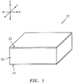
- An example of such a structural panel 20 is schematically shown in FIG. 1 .
- the structural panel 20 of FIG. 1 is configured as an acoustic panel.
- the structural panel 20, for example, may be configured to attenuate noise generated by an aircraft propulsion system such as, for example, a turbofan propulsion system or a turbojet propulsion system. With such a configuration, the structural panel 20 may be configured to form part of a nacelle of the propulsion system.
- the structural panel 20, for example, may be configured as or with an inner or outer barrel, a translating sleeve, a blocker door, etc.
- the structural panel 20 may be configured with another component / structure of the aircraft such as its fuselage or a wing.
- the structural panel 20 may be configured to also or alternatively attenuate aircraft related noise other than that generated by the propulsion system.
- the structural panel 20 of the present disclosure may alternatively be configured for non-aircraft applications and/or non-sound suppression applications.
- the structural panel 20 of FIG. 1 extends longitudinally along an x-axis.
- the structural panel 20 extends laterally along a y-axis.
- the structural panel 20 extends vertically along a z-axis.
- the term "vertical" is used herein to describe a depthwise panel direction and is not limited to a gravitational up/down direction.
- the x-y plane is shown as a generally flat plane of FIG. 1 .
- the x-y plane and, thus, the structural panel 20 may be curved and/or follow an undulating geometry; e.g., complex 3D curvature.
- the x-y plane and, thus, the structural panel 20 may be arcuate, cylindrical, conical, or tapered with or without radial undulations.
- a solely vertical direction e.g., z-axis
- the vertical direction is a radial direction.
- the structural panel 20 includes a porous first skin 22, a solid non-porous second skin 24 and a cellular core structure 26.
- porous is used herein to describe a body with perforations and/or open cell pores that enable flow of gas through the body.
- non-porous is used herein to describe a body with a configuration that prevents flow of gas through the body; e.g., a body without perforations or open cell pores.
- the core structure 26 is disposed and extends vertically between the first skin 22 and the second skin 24.
- the core structure 26 is also connected to the first skin 22 and the second skin 24.
- the core structure 26, for example, may be welded, brazed, fused, adhered or otherwise bonded to the first skin 22 and/or the second skin 24.
- the core structure 26 may also or alternatively be mechanically fastened to the first skin 22 and/or the second skin 24.
- the first skin 22 may be configured as a relatively thin sheet or layer of material that extends laterally and longitudinally along the x-y plane.
- This first skin material may include, but is not limited to, a metal, a polymer (e.g., thermoplastic or thermoset), a fiber reinforced matrix (e.g., fiberglass composite, carbon fiber composite, aramid fiber composite, etc.), or a combination thereof.
- the first skin 22 has a vertical thickness 28, which extends vertically between opposing side surfaces 30 and 32.
- the first skin 22 includes a plurality of perforations 34; e.g., apertures such as through-holes. Each of these perforations 34 extends generally vertically through the first skin 22 between its side surfaces 30 and 32.
- the second skin 24 may be configured as a relatively thin sheet or layer of (e.g., continuous and uninterrupted) material that extends laterally and longitudinally along the x-y plane (see FIG. 1 ).
- This second skin material may include, but is not limited to, a metal, a polymer (e.g., thermoplastic or thermoset), a fiber reinforced composite (e.g., fiberglass composite, carbon fiber composite, aramid fiber composite, etc.), or a combination thereof.
- the second skin material may be the same as or different than the first skin material.
- the second skin 24 has a vertical thickness 36, which extends vertically between opposing side surfaces 38 and 40. This vertical thickness 36 may be substantially equal to or different (e.g., greater or less) than the vertical thickness 28 of the first skin 22.
- the core structure 26 extends laterally and longitudinally along the x-y plane (see FIG. 1 ).
- the core structure 26 has a vertical thickness 42, which extends vertically between opposing core sides, which are abutted against the first skin 22 and the second skin 24.
- This vertical thickness 42 may be substantially greater than the vertical thickness 28 of first skin 22 and/or the vertical thickness 36 of the second skin 24.
- the vertical thickness 42 for example, may be at least ten to forty times (10-40x), or more, greater than the vertical thickness 28, 36; however, the structural panel 20 of the present disclosure is not limited to such an exemplary embodiment.
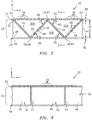
- the core structure 26 includes a plurality of non-porous walls 44, a plurality of non-porous baffles 46 and a plurality of porous septums 48. These components 44, 46 and 48 are arranged together to configure the core structure 26 as an open cavity (e.g., open cell) structure.
- This open cavity structure forms a plurality of cavities 50 (see also FIG. 6 ) vertically between the first skin 22 and the second skin 24.
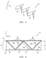
- These cavities 50 may be arranged in a plurality of linear arrays 52 (see FIG. 4 ), where each array 52 extends longitudinally along the x-axis and parallel to the non-porous walls 44.
- Each of the cavities 50 may be fluidly coupled with one or more respective perforations 34 in the first skin 22 (see FIGS. 2 and 3 ).
- Each of the walls 44 may be configured as a (e.g., monolithic) generally planar body, which may be continuous vertically between the first skin 22 and the second skin 24 as well as continuous extending longitudinally along one or more of the cavities 50. Thus, a longitudinal length of each wall 44 may be greater than a vertical height of that same wall 44.
- the walls 44 may be arranged generally parallel with one another. The walls 44 are laterally spaced from one another so as to respectively form the cavities 50 laterally between adjacent walls 44. With this configuration, laterally adjacent cavities 50 (e.g., cavities 50 in laterally adjacent arrays 52) are also fluidly separated from one another by a respective one of the walls 44.
- Each of the walls 44 extends vertically between the first skin 22 and the second skin 24 (see FIGS. 2 and 3 ). Each of the walls 44 may also be connected (e.g., bonded and/or otherwise) to the first skin 22 and/or the second skin 24. Each of the walls 44 is orientated substantially perpendicular to the first skin 22 and the second skin 24. However, in other embodiments, one or more of the walls 44 may be offset from the first skin 22 and/or the second skin 24 by a non-ninety degree angle; e.g., an acute included angle.
- the baffles 46 and the septums 48 are arranged in a plurality of corrugated ribbons 54.
- An exemplary embodiment of such a corrugated ribbon is shown in FIG. 5 .
- This corrugated ribbon may be configured as a (e.g., monolithic) corrugated body, which may be continuous vertically between the first skin 22 and the second skin 24 as well as continuous extending longitudinally along one or more of the cavities 50.
- Each corrugated ribbon 54 includes a plurality of the baffles 46 and a plurality of the septums 48.
- the baffles 46 in each corrugated ribbon are interdisposed with the respective septums 48.
- each of the baffles 46 (unless configured at a longitudinal end of the ribbon 54) is disposed and may extend longitudinally between a respective adjacent pair of the septums 48.
- each of the septums 48 (unless configured at a longitudinal end of the ribbon 54) is disposed and may extend longitudinally between a respective adjacent pair of the baffles 46.
- each of the baffles 46 is vertically engaged with and/or connected to the first skin 22.
- An opposing end 58 of each of the baffles 46 is vertically engaged with and/or connected to the second skin 24.
- each of the baffles 46 may be angularly offset from the first skin 22 and the second skin 24 by an angle 60; e.g., an acute angle or other (e.g., ninety degree) angle.
- one end 62 of each of the septums 48 is vertically engaged with and/or connected to the first skin 22.
- An opposing end 64 of each of the septums 48 is vertically engaged with and/or connected to the second skin 24.
- each of the septums 48 may be angularly offset from the first skin 22 and the second skin 24 by an angle 66; e.g., an acute angle or other (e.g., ninety degree) angle.
- each corrugated ribbon 54 has a corrugated configuration (see FIG. 5 ), where one of the baffles 46 and one of the septums 48 may form a single corrugation.
- one or more of the corrugations may each include at least one additional element; e.g., a bridge.
- each of the cavities 50 extends longitudinally between and is formed by an adjacent pair of the baffles 46.
- Each septum 48 is disposed within and divides a respective one of the cavities 50 into fluidly coupled sub-cavities 50A and 50B.
- One or more perforations 68 in the septum 48 fluidly coupled the sub-cavities 50A and 50B together.
- each of the cavities 50 forms a resonance chamber.
- a length 70 of the resonance chamber extends diagonally between the first skin 22 and the second skin 24 and through a respective one of the septums 48.
- the effective acoustic length 70 of the resonance chamber therefore is longer than the vertical thickness 42 of the core structure 26. This enables noise attenuation of relatively low frequency noise without increasing the vertical thickness of the structural panel 20.
- each resonance chamber may receive noise waves through the perforations in the first skin 22.
- the resonance chamber may reverse the phase of one or more frequencies of those sound waves using known acoustic resonance and noise cancellation principles and subsequently direct the reverse phase sound waves out of the structural panel 20 through the perforations to destructively interfere with other incoming noise waves.
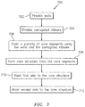
- FIG. 7 is a flow diagram of a method 700 for forming a structural panel such as the structural panel 20 described above and illustrated in FIGS. 1-4 .
- a plurality of the walls 44 are provided. These walls 44 are configured from a polymer such as thermoplastic material, which may include long strand and/or short strand (e.g., chopped) fiber reinforcement embedded therein. Examples of fiber reinforcement include, but are not limited to, fiberglass, carbon fiber and aramid fiber.
- the walls 44 may be formed from stock fiber-reinforced thermoplastic consolidate laminate.
- the walls 44 may be injection molded using thermoplastic material and chopped fibers. The present disclosure, however, is not limited to any particular wall formation techniques or wall materials.
- a plurality of the corrugated ribbons 54 are provided (e.g., see FIG. 5 ).
- These corrugated ribbons 54 are configured from a polymer such as thermoplastic material, which may include long strand and/or short strand (e.g., chopped) fiber reinforcement embedded therein.
- fiber reinforcement include, but are not limited to, fiberglass, carbon fiber and aramid fiber.
- FIG. 8 schematically illustrates an exemplary sequence of processes for forming the corrugated ribbons 54.
- a ribbon of material 72 e.g., fiber-reinforced thermoplastic
- the ribbon of material 72 may be formed from stock fiber-reinforced thermoplastic consolidate laminate, which may be processed (e.g., rolled and/or cut) to provide the ribbon with a predetermined width and thickness. Alternatively, chopped fibers within a thermoplastic resin matrix may be extruded into the ribbon of material 72. Of course, various other processes may also or alternatively be used to provide the ribbon of material 72.
- a plurality of perforations 74 are formed in discrete regions of the ribbon or material 72. These perforations 74 will become the perforations 68 in the septums 48, and the perforated regions will become the septums 48.
- the perforations 74 may be formed in the regions of the ribbon of material 72 via punching, or using any other suitable technique. Of course, in alternative embodiments, the perforations 74 may be formed (e.g., punch, drilled, etc.) after corrugated ribbon 54 and/or core segment 82 formation. In still other embodiments, the perforations 74 may be formed during a stamping process for shaping the ribbons; e.g., at point 808.
- the perforated ribbon of material 72 is heated by a heating element 76.
- a portion of the heated and perforated ribbon of material 72 is formed into one of the corrugated ribbons 54.
- the portion of the heated and perforated ribbon of material 72 may be formed (e.g., stamped) via gear forming rollers 78 (or dies 78).
- the portion of the heated and perforated ribbon may be cut and separated from the remainder of the ribbon of material 72 being processed. Alternatively, the cut may be made after the stamping process.
- a flattener 80 may be used to control the vertical height of the corrugated ribbon 54.
- a plurality of core segments 82 are formed.
- An exemplary embodiment of one of the core segments 82 is shown in FIG. 9 .
- This core segment 82 includes a respective one of the corrugated ribbons 54 and a respective one of the walls 44.
- the corrugated ribbon 54 is disposed adjacent to the wall 44.
- the wall 44 is then bonded to the corrugated ribbon 54 using, for example, ultrasonic welding, resistance welding, consolidation within an autoclave or other means (e.g., tooling with a device for exerting pressure such as a press), welding via induction heating, or adhering with an adhesive.
- other bonding techniques may also or alternatively be used to attach the wall to the corrugated ribbon.
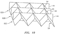
- the core structure 26 is formed.
- the core segments 82 are iteratively bonded to one another in a side-by-side fashion.
- the wall 44 of the second core segment 82B is first bonded to the corrugated ribbon 54 of the first core segment 82A.
- the wall 44 of the third core segment 82C is bonded to the corrugated ribbon 54 of the second core segment 82B.
- a similar process is repeated for the remaining core segments 82 until all of the core segments 82 are bonded together and form the core structure 26.
- Adjacent core segments 82 may be bonded together using, for example, ultrasonic welding, resistance welding, consolidation within an autoclave or other means (e.g., tooling with a device for exerting pressure such as a press), welding via induction heating, or adhering with an adhesive.
- ultrasonic welding an angled horn may be used to provide welding tool access.
- other bonding techniques may also or alternatively be used to attach adjacent core segments 82 together.
- step 710 the first skin 22 is bonded to the core structure 26.
- step 712 the second skin 24 is bonded to the core structure 26.
- the steps 710 and 712 may be performed sequentially (e.g., either 710 and then 712, or 712 and then 710). Alternatively, the steps 710 and 712 may be performed substantially simultaneously.
- the first skin 22 may be perforated before being bonded to the core structure 26. In other embodiments, the first skin 22 may be perforated after being bonded to the core structure 26.
- the structural panel 20 may have a complex curvature; e.g., curved along both the x-axis and y-axis.
- one or more of the corrugated ribbons 54 may be shaped (e.g., via thermoforming) to follow a curved contour before bonding those ribbons to the respective walls 44.
- one or more of the core segments 82 may be shaped to follow a curved contour before forming the core structure 26; e.g., bonding the core segments 82 together.
- the core structure 26 may be shaped to follow a curved contour before (or after) being bonded to the first skin 22 and/or the second skin 24.
- the corrugated ribbons 54 may be formed using an injection molding process, profile extruded, blow molding process, or otherwise.
- each core segment may be formed as a monolithic body using an injection molding process, blow molding process, or otherwise.
- one of the corrugated ribbons 54 may be formed integrally with one of the walls 44.
- the corrugated ribbons 54 and the walls 44 may be sequentially and iteratively bonded to one another.
- a first of the walls 44 may be bonded to a first side of a first of the corrugated ribbons 54.
- a second of the walls 44 may be bonded to a second (opposing) side of the first of the corrugated ribbons 54.
- a second of the corrugated ribbons 54 may be bonded to the second of the walls 44, etc.
- the foregoing formation techniques may be easily adapted for automation.
- angles 60 and 66 may be used to form panels with geometries and configurations other than that described above.
- the angles 60 and 66 are shown in FIG. 2 as being approximately 45 degrees, in other embodiments those angles may be more or less than 45 degrees; e.g., 60 degrees.
- the angles 60 and 66 are shown as being approximately equal to one another in FIG. 2 , in other embodiments the angles 60 and 66 may have different values.
- the angle 60 may be an acute angle whereas the angle 66 may be approximately 90 degrees.
Landscapes
- Engineering & Computer Science (AREA)
- Aviation & Aerospace Engineering (AREA)
- Combustion & Propulsion (AREA)
- Chemical & Material Sciences (AREA)
- Mechanical Engineering (AREA)
- Manufacturing & Machinery (AREA)
- General Engineering & Computer Science (AREA)
- Physics & Mathematics (AREA)
- Acoustics & Sound (AREA)
- Multimedia (AREA)
- Transportation (AREA)
- Lining Or Joining Of Plastics Or The Like (AREA)
- Laminated Bodies (AREA)
Applications Claiming Priority (1)
| Application Number | Priority Date | Filing Date | Title |
|---|---|---|---|
| US15/431,895 US10414481B2 (en) | 2017-02-14 | 2017-02-14 | Method for forming a structural panel |
Publications (2)
| Publication Number | Publication Date |
|---|---|
| EP3364407A1 true EP3364407A1 (de) | 2018-08-22 |
| EP3364407B1 EP3364407B1 (de) | 2021-09-08 |
Family
ID=61226418
Family Applications (1)
| Application Number | Title | Priority Date | Filing Date |
|---|---|---|---|
| EP18156778.5A Active EP3364407B1 (de) | 2017-02-14 | 2018-02-14 | Verfahren zur herstellung einer bauplatte |
Country Status (2)
| Country | Link |
|---|---|
| US (1) | US10414481B2 (de) |
| EP (1) | EP3364407B1 (de) |
Cited By (2)
| Publication number | Priority date | Publication date | Assignee | Title |
|---|---|---|---|---|
| EP4159997A3 (de) * | 2021-09-13 | 2023-06-14 | Rohr, Inc. | Niederfrequenter akustischer zentralkörper |
| EP4206448A1 (de) * | 2022-01-04 | 2023-07-05 | Rohr, Inc. | Mehrkernige akustikplatte für ein flugzeugantriebssystem |
Families Citing this family (21)
| Publication number | Priority date | Publication date | Assignee | Title |
|---|---|---|---|---|
| FR3060829B1 (fr) * | 2016-12-20 | 2019-05-31 | Airbus Operations | Structure constituant un isolant acoustique |
| US10695986B2 (en) * | 2017-08-22 | 2020-06-30 | Rohr, Inc. | Method for forming a structural panel |
| US11059559B2 (en) * | 2018-03-05 | 2021-07-13 | General Electric Company | Acoustic liners with oblique cellular structures |
| US10906659B2 (en) | 2018-04-03 | 2021-02-02 | Rohr, Inc. | Structured panel with structural reinforcement(s) |
| US11433990B2 (en) * | 2018-07-09 | 2022-09-06 | Rohr, Inc. | Active laminar flow control system with composite panel |
| FR3088848B1 (fr) * | 2018-11-28 | 2020-12-04 | Airbus Operations Sas | Procédé de fabrication d’un élément acoustique d’une structure d’absorption acoustique à partir d’au moins une feuille de matière |
| US11242822B2 (en) * | 2018-12-14 | 2022-02-08 | Rohr, Inc. | Structured panel with multi-panel structure(s) |
| US11398214B2 (en) | 2018-12-14 | 2022-07-26 | Rohr, Inc. | Forming a structured panel with one or more structural reinforcements |
| US11174792B2 (en) * | 2019-05-21 | 2021-11-16 | General Electric Company | System and method for high frequency acoustic dampers with baffles |
| US11600255B2 (en) * | 2020-12-22 | 2023-03-07 | Rohr, Inc. | Acoustic panel core with multi-material and/or multi-layered construction |
| US20240096307A1 (en) * | 2021-02-17 | 2024-03-21 | Mitsubishi Heavy Industries, Ltd. | Panel structure |
| US11970992B2 (en) | 2021-06-03 | 2024-04-30 | General Electric Company | Acoustic cores and tools and methods for forming the same |
| US11867077B2 (en) * | 2021-06-07 | 2024-01-09 | Rohr, Inc. | Acoustic structure with floating interior skin |
| US11993388B2 (en) | 2021-09-02 | 2024-05-28 | Rohr, Inc. | Corrugated stiffening devices utilizing peaks and valleys and methods of manufacture |
| US12014712B2 (en) | 2021-09-02 | 2024-06-18 | Rohr, Inc. | Corrugated acoustic stiffening devices and methods |
| US11780179B2 (en) | 2021-09-02 | 2023-10-10 | Rohr, Inc. | Thermoplastic composite panel with corrugated peaks and troughs stiffening systems and methods |
| US12142253B2 (en) | 2021-10-05 | 2024-11-12 | General Electric Company | Solid adhesive film for acoustic liner and method |
| US20240262066A1 (en) | 2023-02-08 | 2024-08-08 | B/E Aerospace, Inc. | Continuous manufacturing method of acoustic transmission loss panels with resonator network cores |
| FR3150628B1 (fr) * | 2023-06-30 | 2025-10-10 | Safran | Fabrication d’un panneau acoustique par soudage par ultrasons |
| US20250214712A1 (en) * | 2023-12-27 | 2025-07-03 | Rohr, Inc. | Acoustic panel for an aircraft propulsion system |
| US20250214713A1 (en) * | 2023-12-27 | 2025-07-03 | Rohr, Inc. | Acoustic panel for an aircraft propulsion system |
Citations (4)
| Publication number | Priority date | Publication date | Assignee | Title |
|---|---|---|---|---|
| US3734234A (en) * | 1971-11-08 | 1973-05-22 | Lockheed Aircraft Corp | Sound absorption structure |
| US20140034416A1 (en) * | 2011-04-20 | 2014-02-06 | Dresser-Rand Company | Multi-degree of freedom resonator array |
| US20150367953A1 (en) | 2014-06-23 | 2015-12-24 | Rohr, Inc. | Acoustic liner |
| EP3205574A2 (de) * | 2016-02-10 | 2017-08-16 | Rohr, Inc. | Struktureller zellulärer kern mit gewelltem stützwänden |
Family Cites Families (39)
| Publication number | Priority date | Publication date | Assignee | Title |
|---|---|---|---|---|
| US3380206A (en) | 1965-09-29 | 1968-04-30 | Soundlock Corp | Lay-in acoustical ceiling panel with flexible diaphragms |
| US3542152A (en) | 1968-04-08 | 1970-11-24 | Gen Electric | Sound suppression panel |
| US3639106A (en) | 1968-05-06 | 1972-02-01 | Burnley Engineering Products L | Acoustic panel |
| GB1406844A (en) | 1972-09-01 | 1975-09-17 | Short Brothers & Harland Ltd | Sound absorbing panels |
| US3821999A (en) | 1972-09-05 | 1974-07-02 | Mc Donnell Douglas Corp | Acoustic liner |
| US3850261A (en) | 1973-03-01 | 1974-11-26 | Gen Electric | Wide band width single layer sound suppressing panel |
| US3910374A (en) | 1974-03-18 | 1975-10-07 | Rohr Industries Inc | Low frequency structural acoustic attenuator |
| US3948346A (en) | 1974-04-02 | 1976-04-06 | Mcdonnell Douglas Corporation | Multi-layered acoustic liner |
| US4189027A (en) | 1976-08-19 | 1980-02-19 | United Technologies Corporation | Sound suppressor liners |
| US4240519A (en) | 1979-07-02 | 1980-12-23 | United Technologies Corporation | Acoustical turbine engine tail pipe plug |
| US5923003A (en) | 1996-09-09 | 1999-07-13 | Northrop Grumman Corporation | Extended reaction acoustic liner for jet engines and the like |
| US5997985A (en) | 1998-09-10 | 1999-12-07 | Northrop Grumman Corporation | Method of forming acoustic attenuation chambers using laser processing of multi-layered polymer films |
| US6598701B1 (en) | 2000-06-30 | 2003-07-29 | 3M Innovative Properties Company | Shaped microperforated polymeric film sound absorbers and methods of manufacturing the same |
| US7297390B2 (en) | 2002-01-28 | 2007-11-20 | Simmons Richard A | Structural polymer core assembly, method of manufacture and method of use |
| JP4231792B2 (ja) | 2002-03-26 | 2009-03-04 | 宇部日東化成株式会社 | 中空構造板、その製造方法及びその製造装置 |
| GB0223697D0 (en) | 2002-10-14 | 2002-11-20 | Rolls Royce Plc | Acoustic liner for gas turbine engineers |
| US6871725B2 (en) | 2003-02-21 | 2005-03-29 | Jeffrey Don Johnson | Honeycomb core acoustic unit with metallurgically secured deformable septum, and method of manufacture |
| CN100402179C (zh) | 2003-11-20 | 2008-07-16 | 喀山航空工业科学研究院股份公开公司 | 生产具有曲折起皱芯的夹板的方法 |
| US20130266772A1 (en) | 2004-06-15 | 2013-10-10 | John S. Fujii | Three-dimensional wood fiber structural composites |
| US7784283B2 (en) | 2006-05-03 | 2010-08-31 | Rohr, Inc. | Sound-absorbing exhaust nozzle center plug |
| US20110100747A1 (en) | 2006-05-24 | 2011-05-05 | Airbus Operations Gmbh | Sandwich element for the sound-absorbing inner cladding of means of transport, especially for the sound-absorbing inner cladding of aircraft |
| RU2413654C2 (ru) | 2006-05-24 | 2011-03-10 | Эйрбас Дойчланд Гмбх | Многослойный элемент для звукопоглощающей внутренней обшивки транспортного средства, преимущественно самолета |
| FR2912833B1 (fr) | 2007-02-20 | 2009-08-21 | Airbus France Sas | Panneau pour le traitement acoustique |
| FR2915522A1 (fr) | 2007-04-30 | 2008-10-31 | Airbus France Sas | Panneau acoustique a caracteristique acoustique variable |
| FR2922152B1 (fr) | 2007-10-16 | 2009-11-20 | Aircelle Sa | Structure a ame alveolaire pour panneau acoustique |
| FR2925463B1 (fr) | 2007-12-21 | 2010-04-23 | Airbus France | Structure pour le traitement acoustique plus particulierement adaptee a une entree d'air d'une nacelle d'aeronef |
| FR2930764B1 (fr) | 2008-04-30 | 2010-05-07 | Airbus France | Panneau d'attenuation d'ondes intercale entre une motorisation et une entree d'air d'une nacelle d'aeronef |
| US7959109B2 (en) | 2008-07-02 | 2011-06-14 | The Boeing Company | Dual valve apparatus for aircraft engine ice protection and related methods |
| DE102008051241B4 (de) | 2008-10-10 | 2011-06-16 | Airbus Operations Gmbh | Schalldämpfer für ein Hilfstriebwerk eines Flugzeugs |
| US8025122B2 (en) | 2008-11-06 | 2011-09-27 | The Boeing Company | Acoustically treated exhaust centerbody for jet engines and associated methods |
| GB0820597D0 (en) | 2008-11-11 | 2008-12-17 | Rolls Royce Plc | A noise reduction device |
| FR2953058B1 (fr) | 2009-11-23 | 2017-11-03 | Aircelle Sa | Peau acoustique pour un panneau acoustique d'une nacelle d'aeronef |
| DE102011008921A1 (de) | 2011-01-19 | 2012-07-19 | Rolls-Royce Deutschland Ltd & Co Kg | Gasturbinenabgaskonus |
| FR2979385A1 (fr) | 2011-08-22 | 2013-03-01 | Snecma | Panneau d'isolation acoustique pour turbomachine et turbomachine comportant un tel panneau |
| FR2983835B1 (fr) | 2011-12-13 | 2014-02-21 | Airbus Operations Sas | Procede de realisation d'un panneau pour le traitement acoustique |
| US20140349082A1 (en) | 2013-05-21 | 2014-11-27 | The Boeing Company | Folded Core Panel |
| US8820477B1 (en) | 2013-07-29 | 2014-09-02 | The Boeing Company | Acoustic panel |
| US9284726B2 (en) | 2014-04-04 | 2016-03-15 | The Boeing Company | Pyramid waffle core structure and method of fabrication |
| CN104723616B (zh) | 2015-03-17 | 2016-07-06 | 西安交通大学 | 一种轻质正交波纹夹芯复合结构及其制备方法 |
-
2017
- 2017-02-14 US US15/431,895 patent/US10414481B2/en active Active
-
2018
- 2018-02-14 EP EP18156778.5A patent/EP3364407B1/de active Active
Patent Citations (5)
| Publication number | Priority date | Publication date | Assignee | Title |
|---|---|---|---|---|
| US3734234A (en) * | 1971-11-08 | 1973-05-22 | Lockheed Aircraft Corp | Sound absorption structure |
| US20140034416A1 (en) * | 2011-04-20 | 2014-02-06 | Dresser-Rand Company | Multi-degree of freedom resonator array |
| US20150367953A1 (en) | 2014-06-23 | 2015-12-24 | Rohr, Inc. | Acoustic liner |
| EP2960480A1 (de) * | 2014-06-23 | 2015-12-30 | Rohr, Inc. | Schalldämpfende auskleidung |
| EP3205574A2 (de) * | 2016-02-10 | 2017-08-16 | Rohr, Inc. | Struktureller zellulärer kern mit gewelltem stützwänden |
Cited By (5)
| Publication number | Priority date | Publication date | Assignee | Title |
|---|---|---|---|---|
| EP4159997A3 (de) * | 2021-09-13 | 2023-06-14 | Rohr, Inc. | Niederfrequenter akustischer zentralkörper |
| US12078125B2 (en) | 2021-09-13 | 2024-09-03 | Rohr, Inc. | Low-frequency acoustic center body |
| US12116955B2 (en) | 2021-09-13 | 2024-10-15 | Rohr, Inc. | Low-frequency acoustic center body |
| US12448935B2 (en) | 2021-09-13 | 2025-10-21 | Rohr, Inc. | Low-frequency acoustic center body |
| EP4206448A1 (de) * | 2022-01-04 | 2023-07-05 | Rohr, Inc. | Mehrkernige akustikplatte für ein flugzeugantriebssystem |
Also Published As
| Publication number | Publication date |
|---|---|
| US10414481B2 (en) | 2019-09-17 |
| EP3364407B1 (de) | 2021-09-08 |
| US20180229829A1 (en) | 2018-08-16 |
Similar Documents
| Publication | Publication Date | Title |
|---|---|---|
| EP3364407B1 (de) | Verfahren zur herstellung einer bauplatte | |
| EP3447760B1 (de) | Verfahren zur formung einer bauplatte | |
| EP3205574B1 (de) | Struktureller zellulärer kern mit gewellten stützwänden | |
| EP3206203B1 (de) | Akustikplatte mit abgewinkelten gewellten kernstrukturen | |
| EP3232435B1 (de) | Akustikplatte mit gewellten abschirmungen und trennwänden | |
| EP3324400B1 (de) | Akustikplatte mit seitenwandholmen | |
| EP3671727B1 (de) | Formung einer strukturierten platte mit einem oder mehreren strukturellen verstärkungen | |
| EP3324401B1 (de) | Akustikplatte mit seitenwandholmen | |
| EP3748627B1 (de) | Akustikplatte mit einem oder mehreren strukturellen versteifungselementen | |
| EP3422342B1 (de) | Akustikplatte mit faltkammer | |
| US11242822B2 (en) | Structured panel with multi-panel structure(s) | |
| EP3564508A1 (de) | Flugzeugantriebssystemanordnung mit einer oder mehreren akustischen platten | |
| EP3594936B1 (de) | Strukturierte platte mit integrierter haut und seitenwänden | |
| EP4020461A1 (de) | Akustikplattenkernzelle mit trichterförmigem septum | |
| US10906659B2 (en) | Structured panel with structural reinforcement(s) | |
| EP4131252B1 (de) | Akustikplatte mit rekonfigurierbaren kammerverengungen |
Legal Events
| Date | Code | Title | Description |
|---|---|---|---|
| PUAI | Public reference made under article 153(3) epc to a published international application that has entered the european phase |
Free format text: ORIGINAL CODE: 0009012 |
|
| STAA | Information on the status of an ep patent application or granted ep patent |
Free format text: STATUS: THE APPLICATION HAS BEEN PUBLISHED |
|
| AK | Designated contracting states |
Kind code of ref document: A1 Designated state(s): AL AT BE BG CH CY CZ DE DK EE ES FI FR GB GR HR HU IE IS IT LI LT LU LV MC MK MT NL NO PL PT RO RS SE SI SK SM TR |
|
| AX | Request for extension of the european patent |
Extension state: BA ME |
|
| STAA | Information on the status of an ep patent application or granted ep patent |
Free format text: STATUS: REQUEST FOR EXAMINATION WAS MADE |
|
| 17P | Request for examination filed |
Effective date: 20190221 |
|
| RBV | Designated contracting states (corrected) |
Designated state(s): AL AT BE BG CH CY CZ DE DK EE ES FI FR GB GR HR HU IE IS IT LI LT LU LV MC MK MT NL NO PL PT RO RS SE SI SK SM TR |
|
| RIC1 | Information provided on ipc code assigned before grant |
Ipc: B64D 29/00 20060101ALI20210217BHEP Ipc: G10K 11/172 20060101ALN20210217BHEP Ipc: F02C 7/045 20060101ALN20210217BHEP Ipc: F02K 1/82 20060101ALI20210217BHEP Ipc: B64D 33/00 20060101ALI20210217BHEP Ipc: G10K 11/168 20060101AFI20210217BHEP Ipc: F02K 1/34 20060101ALN20210217BHEP Ipc: B64F 5/10 20170101ALI20210217BHEP Ipc: B64C 1/40 20060101ALI20210217BHEP Ipc: B64D 33/02 20060101ALN20210217BHEP |
|
| GRAP | Despatch of communication of intention to grant a patent |
Free format text: ORIGINAL CODE: EPIDOSNIGR1 |
|
| STAA | Information on the status of an ep patent application or granted ep patent |
Free format text: STATUS: GRANT OF PATENT IS INTENDED |
|
| RIC1 | Information provided on ipc code assigned before grant |
Ipc: B64D 33/00 20060101ALI20210301BHEP Ipc: B64C 1/40 20060101ALI20210301BHEP Ipc: F02K 1/34 20060101ALN20210301BHEP Ipc: G10K 11/168 20060101AFI20210301BHEP Ipc: B64F 5/10 20170101ALI20210301BHEP Ipc: F02C 7/045 20060101ALN20210301BHEP Ipc: B64D 33/02 20060101ALN20210301BHEP Ipc: B64D 29/00 20060101ALI20210301BHEP Ipc: F02K 1/82 20060101ALI20210301BHEP Ipc: G10K 11/172 20060101ALN20210301BHEP |
|
| INTG | Intention to grant announced |
Effective date: 20210330 |
|
| RIC1 | Information provided on ipc code assigned before grant |
Ipc: F02K 1/34 20060101ALN20210322BHEP Ipc: B64D 33/02 20060101ALN20210322BHEP Ipc: F02C 7/045 20060101ALN20210322BHEP Ipc: G10K 11/172 20060101ALN20210322BHEP Ipc: B64F 5/10 20170101ALI20210322BHEP Ipc: B64D 33/00 20060101ALI20210322BHEP Ipc: F02K 1/82 20060101ALI20210322BHEP Ipc: B64D 29/00 20060101ALI20210322BHEP Ipc: B64C 1/40 20060101ALI20210322BHEP Ipc: G10K 11/168 20060101AFI20210322BHEP |
|
| GRAS | Grant fee paid |
Free format text: ORIGINAL CODE: EPIDOSNIGR3 |
|
| GRAA | (expected) grant |
Free format text: ORIGINAL CODE: 0009210 |
|
| STAA | Information on the status of an ep patent application or granted ep patent |
Free format text: STATUS: THE PATENT HAS BEEN GRANTED |
|
| AK | Designated contracting states |
Kind code of ref document: B1 Designated state(s): AL AT BE BG CH CY CZ DE DK EE ES FI FR GB GR HR HU IE IS IT LI LT LU LV MC MK MT NL NO PL PT RO RS SE SI SK SM TR |
|
| REG | Reference to a national code |
Ref country code: GB Ref legal event code: FG4D |
|
| REG | Reference to a national code |
Ref country code: CH Ref legal event code: EP Ref country code: AT Ref legal event code: REF Ref document number: 1429303 Country of ref document: AT Kind code of ref document: T Effective date: 20210915 |
|
| REG | Reference to a national code |
Ref country code: DE Ref legal event code: R096 Ref document number: 602018023110 Country of ref document: DE |
|
| REG | Reference to a national code |
Ref country code: IE Ref legal event code: FG4D |
|
| REG | Reference to a national code |
Ref country code: LT Ref legal event code: MG9D |
|
| REG | Reference to a national code |
Ref country code: NL Ref legal event code: MP Effective date: 20210908 |
|
| PG25 | Lapsed in a contracting state [announced via postgrant information from national office to epo] |
Ref country code: HR Free format text: LAPSE BECAUSE OF FAILURE TO SUBMIT A TRANSLATION OF THE DESCRIPTION OR TO PAY THE FEE WITHIN THE PRESCRIBED TIME-LIMIT Effective date: 20210908 Ref country code: FI Free format text: LAPSE BECAUSE OF FAILURE TO SUBMIT A TRANSLATION OF THE DESCRIPTION OR TO PAY THE FEE WITHIN THE PRESCRIBED TIME-LIMIT Effective date: 20210908 Ref country code: ES Free format text: LAPSE BECAUSE OF FAILURE TO SUBMIT A TRANSLATION OF THE DESCRIPTION OR TO PAY THE FEE WITHIN THE PRESCRIBED TIME-LIMIT Effective date: 20210908 Ref country code: SE Free format text: LAPSE BECAUSE OF FAILURE TO SUBMIT A TRANSLATION OF THE DESCRIPTION OR TO PAY THE FEE WITHIN THE PRESCRIBED TIME-LIMIT Effective date: 20210908 Ref country code: RS Free format text: LAPSE BECAUSE OF FAILURE TO SUBMIT A TRANSLATION OF THE DESCRIPTION OR TO PAY THE FEE WITHIN THE PRESCRIBED TIME-LIMIT Effective date: 20210908 Ref country code: NO Free format text: LAPSE BECAUSE OF FAILURE TO SUBMIT A TRANSLATION OF THE DESCRIPTION OR TO PAY THE FEE WITHIN THE PRESCRIBED TIME-LIMIT Effective date: 20211208 Ref country code: LT Free format text: LAPSE BECAUSE OF FAILURE TO SUBMIT A TRANSLATION OF THE DESCRIPTION OR TO PAY THE FEE WITHIN THE PRESCRIBED TIME-LIMIT Effective date: 20210908 Ref country code: BG Free format text: LAPSE BECAUSE OF FAILURE TO SUBMIT A TRANSLATION OF THE DESCRIPTION OR TO PAY THE FEE WITHIN THE PRESCRIBED TIME-LIMIT Effective date: 20211208 |
|
| REG | Reference to a national code |
Ref country code: AT Ref legal event code: MK05 Ref document number: 1429303 Country of ref document: AT Kind code of ref document: T Effective date: 20210908 |
|
| PG25 | Lapsed in a contracting state [announced via postgrant information from national office to epo] |
Ref country code: LV Free format text: LAPSE BECAUSE OF FAILURE TO SUBMIT A TRANSLATION OF THE DESCRIPTION OR TO PAY THE FEE WITHIN THE PRESCRIBED TIME-LIMIT Effective date: 20210908 Ref country code: GR Free format text: LAPSE BECAUSE OF FAILURE TO SUBMIT A TRANSLATION OF THE DESCRIPTION OR TO PAY THE FEE WITHIN THE PRESCRIBED TIME-LIMIT Effective date: 20211209 |
|
| PG25 | Lapsed in a contracting state [announced via postgrant information from national office to epo] |
Ref country code: AT Free format text: LAPSE BECAUSE OF FAILURE TO SUBMIT A TRANSLATION OF THE DESCRIPTION OR TO PAY THE FEE WITHIN THE PRESCRIBED TIME-LIMIT Effective date: 20210908 |
|
| PG25 | Lapsed in a contracting state [announced via postgrant information from national office to epo] |
Ref country code: IS Free format text: LAPSE BECAUSE OF FAILURE TO SUBMIT A TRANSLATION OF THE DESCRIPTION OR TO PAY THE FEE WITHIN THE PRESCRIBED TIME-LIMIT Effective date: 20220108 Ref country code: SM Free format text: LAPSE BECAUSE OF FAILURE TO SUBMIT A TRANSLATION OF THE DESCRIPTION OR TO PAY THE FEE WITHIN THE PRESCRIBED TIME-LIMIT Effective date: 20210908 Ref country code: SK Free format text: LAPSE BECAUSE OF FAILURE TO SUBMIT A TRANSLATION OF THE DESCRIPTION OR TO PAY THE FEE WITHIN THE PRESCRIBED TIME-LIMIT Effective date: 20210908 Ref country code: RO Free format text: LAPSE BECAUSE OF FAILURE TO SUBMIT A TRANSLATION OF THE DESCRIPTION OR TO PAY THE FEE WITHIN THE PRESCRIBED TIME-LIMIT Effective date: 20210908 Ref country code: PT Free format text: LAPSE BECAUSE OF FAILURE TO SUBMIT A TRANSLATION OF THE DESCRIPTION OR TO PAY THE FEE WITHIN THE PRESCRIBED TIME-LIMIT Effective date: 20220110 Ref country code: PL Free format text: LAPSE BECAUSE OF FAILURE TO SUBMIT A TRANSLATION OF THE DESCRIPTION OR TO PAY THE FEE WITHIN THE PRESCRIBED TIME-LIMIT Effective date: 20210908 Ref country code: NL Free format text: LAPSE BECAUSE OF FAILURE TO SUBMIT A TRANSLATION OF THE DESCRIPTION OR TO PAY THE FEE WITHIN THE PRESCRIBED TIME-LIMIT Effective date: 20210908 Ref country code: EE Free format text: LAPSE BECAUSE OF FAILURE TO SUBMIT A TRANSLATION OF THE DESCRIPTION OR TO PAY THE FEE WITHIN THE PRESCRIBED TIME-LIMIT Effective date: 20210908 Ref country code: CZ Free format text: LAPSE BECAUSE OF FAILURE TO SUBMIT A TRANSLATION OF THE DESCRIPTION OR TO PAY THE FEE WITHIN THE PRESCRIBED TIME-LIMIT Effective date: 20210908 Ref country code: AL Free format text: LAPSE BECAUSE OF FAILURE TO SUBMIT A TRANSLATION OF THE DESCRIPTION OR TO PAY THE FEE WITHIN THE PRESCRIBED TIME-LIMIT Effective date: 20210908 |
|
| REG | Reference to a national code |
Ref country code: DE Ref legal event code: R097 Ref document number: 602018023110 Country of ref document: DE |
|
| PLBE | No opposition filed within time limit |
Free format text: ORIGINAL CODE: 0009261 |
|
| STAA | Information on the status of an ep patent application or granted ep patent |
Free format text: STATUS: NO OPPOSITION FILED WITHIN TIME LIMIT |
|
| PG25 | Lapsed in a contracting state [announced via postgrant information from national office to epo] |
Ref country code: DK Free format text: LAPSE BECAUSE OF FAILURE TO SUBMIT A TRANSLATION OF THE DESCRIPTION OR TO PAY THE FEE WITHIN THE PRESCRIBED TIME-LIMIT Effective date: 20210908 |
|
| 26N | No opposition filed |
Effective date: 20220609 |
|
| PG25 | Lapsed in a contracting state [announced via postgrant information from national office to epo] |
Ref country code: SI Free format text: LAPSE BECAUSE OF FAILURE TO SUBMIT A TRANSLATION OF THE DESCRIPTION OR TO PAY THE FEE WITHIN THE PRESCRIBED TIME-LIMIT Effective date: 20210908 |
|
| PG25 | Lapsed in a contracting state [announced via postgrant information from national office to epo] |
Ref country code: MC Free format text: LAPSE BECAUSE OF FAILURE TO SUBMIT A TRANSLATION OF THE DESCRIPTION OR TO PAY THE FEE WITHIN THE PRESCRIBED TIME-LIMIT Effective date: 20210908 |
|
| REG | Reference to a national code |
Ref country code: CH Ref legal event code: PL |
|
| REG | Reference to a national code |
Ref country code: BE Ref legal event code: MM Effective date: 20220228 |
|
| PG25 | Lapsed in a contracting state [announced via postgrant information from national office to epo] |
Ref country code: LU Free format text: LAPSE BECAUSE OF NON-PAYMENT OF DUE FEES Effective date: 20220214 |
|
| PG25 | Lapsed in a contracting state [announced via postgrant information from national office to epo] |
Ref country code: LI Free format text: LAPSE BECAUSE OF NON-PAYMENT OF DUE FEES Effective date: 20220228 Ref country code: IT Free format text: LAPSE BECAUSE OF FAILURE TO SUBMIT A TRANSLATION OF THE DESCRIPTION OR TO PAY THE FEE WITHIN THE PRESCRIBED TIME-LIMIT Effective date: 20210908 Ref country code: IE Free format text: LAPSE BECAUSE OF NON-PAYMENT OF DUE FEES Effective date: 20220214 Ref country code: CH Free format text: LAPSE BECAUSE OF NON-PAYMENT OF DUE FEES Effective date: 20220228 |
|
| PG25 | Lapsed in a contracting state [announced via postgrant information from national office to epo] |
Ref country code: BE Free format text: LAPSE BECAUSE OF NON-PAYMENT OF DUE FEES Effective date: 20220228 |
|
| PG25 | Lapsed in a contracting state [announced via postgrant information from national office to epo] |
Ref country code: HU Free format text: LAPSE BECAUSE OF FAILURE TO SUBMIT A TRANSLATION OF THE DESCRIPTION OR TO PAY THE FEE WITHIN THE PRESCRIBED TIME-LIMIT; INVALID AB INITIO Effective date: 20180214 |
|
| PG25 | Lapsed in a contracting state [announced via postgrant information from national office to epo] |
Ref country code: MK Free format text: LAPSE BECAUSE OF FAILURE TO SUBMIT A TRANSLATION OF THE DESCRIPTION OR TO PAY THE FEE WITHIN THE PRESCRIBED TIME-LIMIT Effective date: 20210908 Ref country code: CY Free format text: LAPSE BECAUSE OF FAILURE TO SUBMIT A TRANSLATION OF THE DESCRIPTION OR TO PAY THE FEE WITHIN THE PRESCRIBED TIME-LIMIT Effective date: 20210908 |
|
| PG25 | Lapsed in a contracting state [announced via postgrant information from national office to epo] |
Ref country code: MT Free format text: LAPSE BECAUSE OF FAILURE TO SUBMIT A TRANSLATION OF THE DESCRIPTION OR TO PAY THE FEE WITHIN THE PRESCRIBED TIME-LIMIT Effective date: 20210908 |
|
| PG25 | Lapsed in a contracting state [announced via postgrant information from national office to epo] |
Ref country code: TR Free format text: LAPSE BECAUSE OF FAILURE TO SUBMIT A TRANSLATION OF THE DESCRIPTION OR TO PAY THE FEE WITHIN THE PRESCRIBED TIME-LIMIT Effective date: 20210908 |
|
| P01 | Opt-out of the competence of the unified patent court (upc) registered |
Free format text: CASE NUMBER: UPC_APP_0017184_3364407/2025 Effective date: 20251211 |
|
| PGFP | Annual fee paid to national office [announced via postgrant information from national office to epo] |
Ref country code: GB Payment date: 20260122 Year of fee payment: 9 |
|
| PGFP | Annual fee paid to national office [announced via postgrant information from national office to epo] |
Ref country code: DE Payment date: 20260121 Year of fee payment: 9 |
|
| PGFP | Annual fee paid to national office [announced via postgrant information from national office to epo] |
Ref country code: FR Payment date: 20260121 Year of fee payment: 9 |