EP3364481B1 - Batteriemodul mit messendem kabelbaum mit verbesserter verbindungsstruktur und verfahren zur montage davon - Google Patents
Batteriemodul mit messendem kabelbaum mit verbesserter verbindungsstruktur und verfahren zur montage davon Download PDFInfo
- Publication number
- EP3364481B1 EP3364481B1 EP17810507.8A EP17810507A EP3364481B1 EP 3364481 B1 EP3364481 B1 EP 3364481B1 EP 17810507 A EP17810507 A EP 17810507A EP 3364481 B1 EP3364481 B1 EP 3364481B1
- Authority
- EP
- European Patent Office
- Prior art keywords
- cell
- wire harness
- lead
- sensing wire
- battery module
- Prior art date
- Legal status (The legal status is an assumption and is not a legal conclusion. Google has not performed a legal analysis and makes no representation as to the accuracy of the status listed.)
- Active
Links
Images


Classifications
-
- H—ELECTRICITY
- H01—ELECTRIC ELEMENTS
- H01M—PROCESSES OR MEANS, e.g. BATTERIES, FOR THE DIRECT CONVERSION OF CHEMICAL ENERGY INTO ELECTRICAL ENERGY
- H01M50/00—Constructional details or processes of manufacture of the non-active parts of electrochemical cells other than fuel cells, e.g. hybrid cells
- H01M50/20—Mountings; Secondary casings or frames; Racks, modules or packs; Suspension devices; Shock absorbers; Transport or carrying devices; Holders
-
- H—ELECTRICITY
- H01—ELECTRIC ELEMENTS
- H01R—ELECTRICALLY-CONDUCTIVE CONNECTIONS; STRUCTURAL ASSOCIATIONS OF A PLURALITY OF MUTUALLY-INSULATED ELECTRICAL CONNECTING ELEMENTS; COUPLING DEVICES; CURRENT COLLECTORS
- H01R4/00—Electrically-conductive connections between two or more conductive members in direct contact, i.e. touching one another; Means for effecting or maintaining such contact; Electrically-conductive connections having two or more spaced connecting locations for conductors and using contact members penetrating insulation
- H01R4/28—Clamped connections, spring connections
- H01R4/30—Clamped connections, spring connections utilising a screw or nut clamping member
-
- H—ELECTRICITY
- H01—ELECTRIC ELEMENTS
- H01M—PROCESSES OR MEANS, e.g. BATTERIES, FOR THE DIRECT CONVERSION OF CHEMICAL ENERGY INTO ELECTRICAL ENERGY
- H01M10/00—Secondary cells; Manufacture thereof
- H01M10/42—Methods or arrangements for servicing or maintenance of secondary cells or secondary half-cells
- H01M10/48—Accumulators combined with arrangements for measuring, testing or indicating the condition of cells, e.g. the level or density of the electrolyte
-
- H—ELECTRICITY
- H01—ELECTRIC ELEMENTS
- H01M—PROCESSES OR MEANS, e.g. BATTERIES, FOR THE DIRECT CONVERSION OF CHEMICAL ENERGY INTO ELECTRICAL ENERGY
- H01M10/00—Secondary cells; Manufacture thereof
- H01M10/42—Methods or arrangements for servicing or maintenance of secondary cells or secondary half-cells
- H01M10/48—Accumulators combined with arrangements for measuring, testing or indicating the condition of cells, e.g. the level or density of the electrolyte
- H01M10/482—Accumulators combined with arrangements for measuring, testing or indicating the condition of cells, e.g. the level or density of the electrolyte for several batteries or cells simultaneously or sequentially
-
- H—ELECTRICITY
- H01—ELECTRIC ELEMENTS
- H01M—PROCESSES OR MEANS, e.g. BATTERIES, FOR THE DIRECT CONVERSION OF CHEMICAL ENERGY INTO ELECTRICAL ENERGY
- H01M50/00—Constructional details or processes of manufacture of the non-active parts of electrochemical cells other than fuel cells, e.g. hybrid cells
- H01M50/20—Mountings; Secondary casings or frames; Racks, modules or packs; Suspension devices; Shock absorbers; Transport or carrying devices; Holders
- H01M50/204—Racks, modules or packs for multiple batteries or multiple cells
- H01M50/207—Racks, modules or packs for multiple batteries or multiple cells characterised by their shape
- H01M50/211—Racks, modules or packs for multiple batteries or multiple cells characterised by their shape adapted for pouch cells
-
- H—ELECTRICITY
- H01—ELECTRIC ELEMENTS
- H01M—PROCESSES OR MEANS, e.g. BATTERIES, FOR THE DIRECT CONVERSION OF CHEMICAL ENERGY INTO ELECTRICAL ENERGY
- H01M50/00—Constructional details or processes of manufacture of the non-active parts of electrochemical cells other than fuel cells, e.g. hybrid cells
- H01M50/50—Current conducting connections for cells or batteries
- H01M50/502—Interconnectors for connecting terminals of adjacent batteries; Interconnectors for connecting cells outside a battery casing
- H01M50/514—Methods for interconnecting adjacent batteries or cells
- H01M50/516—Methods for interconnecting adjacent batteries or cells by welding, soldering or brazing
-
- H—ELECTRICITY
- H01—ELECTRIC ELEMENTS
- H01M—PROCESSES OR MEANS, e.g. BATTERIES, FOR THE DIRECT CONVERSION OF CHEMICAL ENERGY INTO ELECTRICAL ENERGY
- H01M50/00—Constructional details or processes of manufacture of the non-active parts of electrochemical cells other than fuel cells, e.g. hybrid cells
- H01M50/50—Current conducting connections for cells or batteries
- H01M50/502—Interconnectors for connecting terminals of adjacent batteries; Interconnectors for connecting cells outside a battery casing
- H01M50/514—Methods for interconnecting adjacent batteries or cells
- H01M50/517—Methods for interconnecting adjacent batteries or cells by fixing means, e.g. screws, rivets or bolts
-
- Y—GENERAL TAGGING OF NEW TECHNOLOGICAL DEVELOPMENTS; GENERAL TAGGING OF CROSS-SECTIONAL TECHNOLOGIES SPANNING OVER SEVERAL SECTIONS OF THE IPC; TECHNICAL SUBJECTS COVERED BY FORMER USPC CROSS-REFERENCE ART COLLECTIONS [XRACs] AND DIGESTS
- Y02—TECHNOLOGIES OR APPLICATIONS FOR MITIGATION OR ADAPTATION AGAINST CLIMATE CHANGE
- Y02E—REDUCTION OF GREENHOUSE GAS [GHG] EMISSIONS, RELATED TO ENERGY GENERATION, TRANSMISSION OR DISTRIBUTION
- Y02E60/00—Enabling technologies; Technologies with a potential or indirect contribution to GHG emissions mitigation
- Y02E60/10—Energy storage using batteries
-
- Y—GENERAL TAGGING OF NEW TECHNOLOGICAL DEVELOPMENTS; GENERAL TAGGING OF CROSS-SECTIONAL TECHNOLOGIES SPANNING OVER SEVERAL SECTIONS OF THE IPC; TECHNICAL SUBJECTS COVERED BY FORMER USPC CROSS-REFERENCE ART COLLECTIONS [XRACs] AND DIGESTS
- Y02—TECHNOLOGIES OR APPLICATIONS FOR MITIGATION OR ADAPTATION AGAINST CLIMATE CHANGE
- Y02P—CLIMATE CHANGE MITIGATION TECHNOLOGIES IN THE PRODUCTION OR PROCESSING OF GOODS
- Y02P70/00—Climate change mitigation technologies in the production process for final industrial or consumer products
- Y02P70/50—Manufacturing or production processes characterised by the final manufactured product
Definitions
- the present disclosure relates to a battery module and an assembly method thereof, and more particularly, to a battery mode having an improved connection structure between a cell and a voltage sensing wire harness, and an assembly method thereof.
- a battery module has a structure in which a plurality of cells are gathered through series and/or parallel connection.
- Such a battery module is manufactured in a structure including a cell assembly in which a plurality of cells are generally arranged in one direction and are substantially stacked on each other.
- a battery module employs, for voltage detection with respect to each cell, a sensing assembly including a printed circuit board (PCB) 12 disposed on an the top of a body of a cell assembly 10, a connector 13 mounted on the PCB 12 to access a predetermined sensing circuit unit, and a plurality of bus bars 14 protruding from two edges of the PCB 12 based on a length direction and connected to a cell lead 11, as shown in FIGS. 1 and 2 .
- PCB printed circuit board
- the structure of the sensing assembly is realized via assembly processes including operations of fixing the PCB 12 to a top of a module body, while welding the bus bar 14 when the bus bar 14 is inserted into a bottom of the cell lead 11.
- the bus bar 14 i.e., a separate metal
- the bus bar 14 needs to be separately designed and manufactured, and then mounted on the PCB 12, and thus production costs may be high.
- space utility is poor.
- EP2791997A1 and US2016/072112A1 disclose battery modules with battery connector systems.
- Korean Patent Application Publication No. 2014-0084563 discloses a voltage sensing circuit of a car battery, in which each of sensing bus bars is bonded to a cell lead via laser welding, and wires are connected to each of the sensing bus bars to discharge current flowed into the sensing bus bars.
- a method requires a separate sensing bus bar as described above, and thus reducing of production costs may be limited.
- a process of laser-welding the sensing bus bar to the cell lead, and a process of bending a compressed piece formed on the sensing bus bar and pressing the compressed piece to one end of the wire to be connected thereto need to be accompanied, large process costs are still required.
- the present disclosure is designed to solve the problems of the related art, and therefore the present disclosure is directed to providing a battery module having a structure capable of simplifying a bonding process between a cell lead and a voltage sensing wire harness and capable of reducing volume of a module, and an assembly method thereof.
- the present disclosure is also directed to providing a battery module capable of preventing occurrence of deformation in a lead plate while welding a sensing wire harness and a cell lead, and an assembly method thereof.
- a battery module including: a cell assembly in which a plurality of cells are arranged at a predetermined interval, wherein each of the plurality of cells includes a cell lead; a sensing wire harness disposed around the cell lead and including a connecting terminal corresponding to the cell lead, wherein the connecting terminal is directly bonded to the cell lead; and a connector connected to the sensing wire harness by being fixed at one side of the cell assembly.
- the connecting terminal of the sensing wire harness is directly bonded to the cell lead via welding.
- the cell lead may be provided on two sides of the connector at a predetermined interval, and the sensing wire harness may extend in an arrangement direction of the cell lead.
- the connector may be fixed to a body of the cell assembly by a screw member.
- the cell lead includes a first lead plate and a second lead plate that overlap each other.
- Each of the first lead plate and the second lead plate is formed of at least two layers of thin slices.
- an assembly method of a battery module including: (a) preparing a cell assembly in which a plurality of cells are arranged, wherein each of the plurality of cells includes a cell lead; (b) locating a sensing wire harness including a connecting terminal around the cell lead; (c) aligning the connecting terminal of the sensing wire harness to correspond to each cell lead; and (d) directly bonding the connecting terminal to the cell lead.
- the connecting terminal of the sensing wire harness may be directly welded to the cell lead by performing ultrasonic welding or laser welding.
- the welding may be performed while the connecting terminal of the sensing wire harness is aligned to correspond to the cell lead by using a jig.
- the operation (b) may further include disposing a connector connectable to the sensing wire harness on a top of a body of the cell assembly and fixing the connector by using a screw member.
- the connector may be disposed such that the cell lead is located on two sides of the connector.
- the cell lead may be disposed at two sides of the connector at a predetermined interval and the sensing wire harness may be disposed to extend in an arrangement direction of the cell lead.
- an assembly method of a battery module including: (1) preparing a cell assembly in which a plurality of cells are arranged at a predetermined interval, wherein a cell lead including a first lead plate is drawn out from each of the plurality of cells; (2) preparing a sensing wire harness including a connecting terminal and directly bonding a second lead plate to the connecting terminal; (3) locating the sensing wire harness around the cell lead; and (4) bonding the first lead plate and the second lead plate to overlap each other.
- the connecting terminal of the sensing wire harness may be directly welded to the second lead plate by performing ultrasonic welding or laser welding.
- the assembly method may further include disposing a connector connectable to the sensing wire harness on a top of a body of the cell assembly, and fixing the connector by using a screw member.
- the connector may be disposed such that the cell lead is located on two sides of the connector.
- the cell lead may be disposed at two sides of the connector at a predetermined interval and the sensing wire harness may be disposed to extend in an arrangement direction of the cell lead.
- assembly process costs may be reduced by simplifying a bonding process between a cell lead and a voltage sensing wire harness.
- connection metal and a fixing structure thereof may be omitted by directly welding a cell lead and a wire harness, material costs may be reduced and space utility may be increased.
- the cell lead may be prevented from being deformed by heat generated during welding.
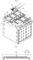
- FIG. 3 is a partial enlarged perspective view of a structure of a battery module according to a preferable embodiment of the present disclosure
- FIG. 4 is a partial exploded view of FIG. 3 .
- a battery module includes a cell assembly 100 in which a plurality of cells are arranged, a sensing wire harness 102 disposed on a top of the cell assembly 100 and directly welded to a cell lead 101, and a connector 103 fixed to a body of the cell assembly 100 and connected to the sensing wire harness 102.
- the plurality of cells are arranged in one direction at a predetermined interval, and the cell lead 101 is drawn out from each cell.
- Each cell has a thin plate shaped body, and preferably, is configured by a pouch type secondary battery.
- the plurality of cells are arranged in one direction of the cell assembly 100 to substantially form a stacked structure.
- a predetermined support frame for fixing each cell is combined to the cell assembly 100.
- the sensing wire harness 102 provides a leading wire for measuring a cell voltage, and includes a plurality of wires each corresponding to the cell lead 101, wherein a connecting terminal 102a that is a welding region is located at the end of each wire.
- the sensing wire harness 102 is disposed on the top of the cell assembly 100 so as to be located around the cell lead 101, and the connecting terminal 102a drawn out from the sensing wire harness 102 is directly bonded to the cell lead 101 via ultrasonic welding or laser welding.
- the connector 103 mediates connection between the sensing wire harness 102 and a predetermined voltage sensing circuit module (not shown), and is directly mounted onto an accommodating part 104 provided on a top of the body of the cell assembly 100.
- a screw coupling unit 105 is provided on the top of the body of the cell assembly 100, and the connector 103 is fixed to the accommodating part 104 via screw coupling with respect to the screw coupling unit 105.
- the sensing wire harness 102 is connected to an input terminal of the connector 103.
- the cell lead 101 is arranged on two sides of the accommodating part 104 at a predetermined interval, and the sensing wire harness 102 is arranged in a longitudinal direction of the accommodating part 104 to extend in an arrangement direction of the cell lead 101.
- FIG. 5 illustrates in detail a connection structure between the cell lead 101 and the sensing wire harness 102.
- the connecting terminal 102a of the sensing wire harness 102 is welded to directly contact a surface part of the cell lead 101.
- An area of a flat surface of the cell lead 101 to which the connecting terminal 102a is welded may be as large as possible such that the connecting terminal 102a of the sensing wire harness 102 is strongly supported and thus a welding operation is smoothly performed.
- the cell lead 101 may be provided in a structure in which a first lead plate 101a and a second lead plate 101b overlap each other.
- the first and second lead plates 101a and 101b may each be formed in at least two layers of thin slices so as to minimize deformation of a cell lead due to thermal expansion occurred during welding.
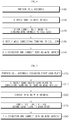
- the connecting terminal 102a of the sensing wire harness 102 is aligned to correspond to the cell lead 101 (operation S120).
- the sensing wire harness 102 maintains a state in which the connecting terminal 102a is placed on an external surface of the cell lead 101 while the sensing wire harness 102 is supported by a predetermined jig.
- the connector 103 that mediates connection between the sensing wire harness 102 and the voltage measuring circuit module is disposed in the accommodating part 104 prepared on the top of the body of the cell assembly 100, and then is fixed by using a screw member. After the connector 103 is fixed, the sensing wire harness 102 is connected to the input terminal of the connector 103 to complete assembly (operation S140).
- FIG. 7 is a flowchart of an assembly method of a battery module according to another embodiment of the present disclosure.
- the cell assembly 100 in which the plurality of cells are arranged in one direction, wherein each cell includes the first lead plate 101a, is prepared (operation S200).
- the second lead plate 101b is directly bonded to the connecting terminal 102a of the sensing wire harness 102 (operation S210).
- the connecting terminal 102a of the sensing wire harness 102 is aligned on the second lead plate 101b, and then the connecting terminal 102a is welded and connected to the second lead plate 101b by performing ultrasonic welding or laser welding directly with respect to the connecting terminal 102a.
- the sensing wire harness 102 is provided in the accommodating part 104 while the second lead plate 101b is bonded per connecting terminal 102a (operation S220).
- the first lead plate 101a and the second lead plate 101b are disposed to overlap each other and then a bonding process, such as welding, soldering, or adhering, is performed (operation S230).
- a bonding process such as welding, soldering, or adhering
- the connector 103 that mediates connection between the sensing wire harness and the voltage measuring circuit module is disposed in the accommodating part 104 provided at the top of the body of the cell assembly 100, and then is fixed by using a screw member.
- a fixing process of the connector 103 may be performed before a disposing process of the sensing wire harness 102.
- the sensing wire harness 102 is connected to the input terminal of the connector 103 to complete assembly (operation S240).
- the cell lead 101 and the sensing wire harness 102 are connected to each other by being directly welded to each other, a separate connection metal and a fixing structure thereof are omitted unlike existing technology, and thus production costs may be reduced and the volume of a module may be reduced.
- production costs of a battery module may be reduced and the volume of the battery module may be reduced.
Landscapes
- Chemical & Material Sciences (AREA)
- Chemical Kinetics & Catalysis (AREA)
- Electrochemistry (AREA)
- General Chemical & Material Sciences (AREA)
- Engineering & Computer Science (AREA)
- Manufacturing & Machinery (AREA)
- Connection Of Batteries Or Terminals (AREA)
- Battery Mounting, Suspending (AREA)
Claims (5)
- Batteriemodul, umfassend:eine Zellenanordnung (100), in welcher eine Mehrzahl von Zellen in einem vorbestimmten Intervall angeordnet sind, wobei jede der Mehrzahl von Zellen eine Zellenleitung (101) umfasst;einen Sensor-Kabelbaum (102), welcher um die Zellenleitung herum angeordnet ist und einen Verbindungsanschluss (102a) umfasst, welcher der Zellenleitung entspricht, wobei der Verbindunganschluss unmittelbar mit der Zellenleitung verbunden ist; undeinen Verbindungsteil (103), welcher mit dem Sensor-Kabelbaum verbunden ist, indem er an einer Seite der Zellenanordnung fixiert ist,wobei der Verbindungsanschluss (102a) des Sensor-Kabelbaums (102) durch Schweißen unmittelbar mit der Zellenleitung (101) verbunden ist,wobei die Zellenleitung (101) eine erste Leitungsplatte (101a) und eine zweite Leitungsplatte (101b) umfasst, die einander überlappen, undwobei jede der ersten Leitungsplatte (101a) und der zweiten Leitungsplatte (101b) aus wenigstens zwei Schichten dünner Stücke gebildet ist.
- Batteriemodul nach Anspruch 1, wobei die Zellenleitung in einem vorbestimmten Intervall an zwei Seiten der Verbindungsleitung bereitgestellt ist, und
sich der Sensor-Kabelbaum in einer Anordnungsrichtung der Zellenleitung erstreckt. - Batteriemodul nach Anspruch 1, wobei der Verbindungsteil durch ein Schraubenelement an einem Körper der Zellenanordnung fixiert ist.
- Anordnungsverfahren eines Batteriemoduls, wie in Anspruch 1 definiert, wobei das Anordnungsverfahren umfasst:(1) Herstellen einer Zellenanordnung (100), in welcher eine Mehrzahl von Zellen in einem vorbestimmten Intervall angeordnet ist, wobei eine Zellenleitung (101), welche eine erste Leitungsplatte (101a) umfasst, aus jeder der Mehrzahl von Zellen herausgezogen ist;(2) Herstellen eines Sensor-Kabelbaums (102), welcher einen Verbindungsanschluss (102) umfasst, und unmittelbares Verbinden einer zweiten Leitungsplatte (102b) mit dem Verbindungsanschluss;(3) Anordnen des Sensor-Kabelbaums um die Zellenleitung; und(4) Verbinden der ersten Leitungsplatte und der zweiten Leitungsplatte derart, dass sie einander überlappen,wobei, in dem Vorgang (2), der Verbindungsanschluss des Sensor-Kabelbaums unmittelbar an die zweite Leitungsplatte geschweißt wird, indem ein Ultraschallschweißen oder ein Laserschweißen durchgeführt wird.
- Anordnungsverfahren nach Anspruch 4, ferner umfassend Anordnen eines Verbindungsteils (103), welcher mit dem Sensor-Kabelbaum verbindbar ist, an einer Oberseite eines Körpers der Zellenanordnung, und Fixieren des Verbindungsteils unter Verwendung eines Schraubenelements.
Priority Applications (1)
| Application Number | Priority Date | Filing Date | Title |
|---|---|---|---|
| PL17810507T PL3364481T3 (pl) | 2016-06-08 | 2017-06-02 | Moduł baterii zawierający wiązkę przewodów czujnikowych o udoskonalonej strukturze połączeń i sposób jej montażu |
Applications Claiming Priority (2)
| Application Number | Priority Date | Filing Date | Title |
|---|---|---|---|
| KR1020160071204A KR102032506B1 (ko) | 2016-06-08 | 2016-06-08 | 센싱 와이어 하네스의 접속 구조가 개선된 배터리 모듈 및 그 조립방법 |
| PCT/KR2017/005797 WO2017213384A1 (ko) | 2016-06-08 | 2017-06-02 | 센싱 와이어 하네스의 접속 구조가 개선된 배터리 모듈 및 그 조립방법 |
Publications (3)
| Publication Number | Publication Date |
|---|---|
| EP3364481A4 EP3364481A4 (de) | 2018-08-22 |
| EP3364481A1 EP3364481A1 (de) | 2018-08-22 |
| EP3364481B1 true EP3364481B1 (de) | 2020-01-29 |
Family
ID=60578929
Family Applications (1)
| Application Number | Title | Priority Date | Filing Date |
|---|---|---|---|
| EP17810507.8A Active EP3364481B1 (de) | 2016-06-08 | 2017-06-02 | Batteriemodul mit messendem kabelbaum mit verbesserter verbindungsstruktur und verfahren zur montage davon |
Country Status (7)
| Country | Link |
|---|---|
| US (1) | US11398662B2 (de) |
| EP (1) | EP3364481B1 (de) |
| JP (1) | JP6595109B2 (de) |
| KR (1) | KR102032506B1 (de) |
| CN (1) | CN208256746U (de) |
| PL (1) | PL3364481T3 (de) |
| WO (1) | WO2017213384A1 (de) |
Families Citing this family (12)
| Publication number | Priority date | Publication date | Assignee | Title |
|---|---|---|---|---|
| US12347832B2 (en) | 2013-09-18 | 2025-07-01 | Ambri, LLC | Electrochemical energy storage devices |
| DK3058605T3 (da) | 2013-10-16 | 2024-03-04 | Ambri Inc | Tætninger til anordninger af reaktivt højtemperaturmateriale |
| US12142735B1 (en) | 2013-11-01 | 2024-11-12 | Ambri, Inc. | Thermal management of liquid metal batteries |
| CN112909437B (zh) * | 2018-07-23 | 2022-11-08 | 宁德时代新能源科技股份有限公司 | 采样组件及电池模组 |
| AU2019405440A1 (en) | 2018-12-17 | 2021-08-12 | Ambri, LLC | High temperature energy storage systems and methods |
| CN109877725B (zh) * | 2019-04-23 | 2024-02-09 | 星云智能装备(昆山)有限公司 | 一种电池模组提取器 |
| KR102836078B1 (ko) * | 2019-10-18 | 2025-07-17 | 주식회사 엘지에너지솔루션 | 용접용 지그 |
| CN112952244B (zh) * | 2019-11-22 | 2022-10-18 | 比亚迪股份有限公司 | 一种电池、电池模组、电池包和电动车 |
| KR102812890B1 (ko) | 2019-12-18 | 2025-05-23 | 주식회사 엘지에너지솔루션 | 복수의 단위 모듈과 bms 어셈블리를 포함하는 서브 팩 및 이를 포함하는 배터리 팩 |
| KR102951291B1 (ko) * | 2020-07-22 | 2026-04-09 | 주식회사 엘지에너지솔루션 | 전극 리드와 전압 센싱부재 간의 연결을 단순화한 배터리 모듈 및 이를 포함하는 배터리 팩 |
| WO2023147070A1 (en) * | 2022-01-27 | 2023-08-03 | Ambri Inc. | Improved energy storage devices |
| JPWO2024038730A1 (de) * | 2022-08-17 | 2024-02-22 |
Family Cites Families (29)
| Publication number | Priority date | Publication date | Assignee | Title |
|---|---|---|---|---|
| JP3485162B2 (ja) * | 1998-10-09 | 2004-01-13 | 矢崎総業株式会社 | バッテリ用接続プレートおよびその製造方法 |
| JP4224671B2 (ja) * | 2002-03-13 | 2009-02-18 | 住友電気工業株式会社 | 電力貯蔵デバイスおよびこれに用いられるリードユニット |
| JP5034152B2 (ja) * | 2004-03-16 | 2012-09-26 | 株式会社Gsユアサ | 組電池 |
| DE102004052831A1 (de) | 2004-10-29 | 2006-05-04 | Abertax Research And Development Ltd. | System mit Batterieeinheiten und zugehörigen Anschlussverbindern |
| JP5042480B2 (ja) | 2005-08-30 | 2012-10-03 | 富士重工業株式会社 | 電源装置の外部接続端子構造 |
| US7448904B2 (en) * | 2006-10-26 | 2008-11-11 | Cooper Technologies Company | Low-profile power supply terminal assembly |
| JP5151115B2 (ja) * | 2006-11-02 | 2013-02-27 | 日産自動車株式会社 | 双極型二次電池 |
| KR101054833B1 (ko) | 2007-10-29 | 2011-08-05 | 에스케이이노베이션 주식회사 | 리튬 2차 전지 단위 셋 및 리튬 2차 전지 셋 |
| JP5340676B2 (ja) | 2008-08-29 | 2013-11-13 | 三洋電機株式会社 | バッテリシステム |
| EP2416436B1 (de) * | 2009-04-01 | 2018-02-21 | LG Chem, Ltd. | Spannungserkennungselement und batteriemodul damit |
| JP2011198598A (ja) * | 2010-03-19 | 2011-10-06 | Panasonic Corp | リード線付電池及びその製造方法 |
| KR101403779B1 (ko) | 2010-05-26 | 2014-06-03 | 스미도모쥬기가이고교 가부시키가이샤 | 축전모듈을 구비한 쇼벨 |
| KR101274859B1 (ko) * | 2011-03-04 | 2013-06-13 | 로베르트 보쉬 게엠베하 | 이차 전지 및 그 조립 방법 |
| KR101802926B1 (ko) | 2011-04-25 | 2017-11-29 | 에스케이이노베이션 주식회사 | 셀의 신호 처리를 위한 센싱 어셈블리를 가지는 배터리 |
| JP6151476B2 (ja) | 2011-10-19 | 2017-06-21 | 矢崎総業株式会社 | 電源装置 |
| US8808031B2 (en) | 2011-12-14 | 2014-08-19 | Tyco Electronics Corporation | Battery connector system |
| JP2014049343A (ja) | 2012-08-31 | 2014-03-17 | Toshiba Corp | 電池パック |
| KR101456936B1 (ko) | 2012-12-27 | 2014-10-31 | 에이치엘그린파워 주식회사 | 차량용 배터리의 전압센싱회로 및 이를 포함하는 셀모듈조립체 |
| KR20140129401A (ko) * | 2013-04-18 | 2014-11-07 | 에스케이이노베이션 주식회사 | 배터리 모듈 |
| JP2014216248A (ja) * | 2013-04-26 | 2014-11-17 | 三菱自動車工業株式会社 | バッテリケース |
| JP6115298B2 (ja) * | 2013-05-09 | 2017-04-19 | 株式会社デンソー | 組電池の製造方法 |
| JP5772885B2 (ja) * | 2013-06-25 | 2015-09-02 | 三洋電機株式会社 | バッテリシステム |
| WO2015061443A1 (en) * | 2013-10-25 | 2015-04-30 | Quantumscape Corporation | Thermal and electrical management of battery packs |
| US9368882B2 (en) * | 2013-11-15 | 2016-06-14 | Yazaki North America, Inc. | Electrical device with a busbar assembly having a frame providing access for laser welding |
| KR20150062777A (ko) * | 2013-11-29 | 2015-06-08 | 주식회사 엘지화학 | 배터리 모듈 및 이를 포함하는 배터리 팩 |
| KR101699865B1 (ko) * | 2013-12-17 | 2017-01-25 | 주식회사 엘지화학 | 직접 연결 방식의 전압 센싱부를 포함하는 전지모듈 |
| JP2015201274A (ja) * | 2014-04-04 | 2015-11-12 | トヨタ自動車株式会社 | 電池監視装置 |
| US9620761B2 (en) * | 2014-09-09 | 2017-04-11 | Lg Chem, Ltd. | Battery cell interconnect and voltage sensing assembly and a battery module |
| JP6380043B2 (ja) | 2014-11-21 | 2018-08-29 | 株式会社オートネットワーク技術研究所 | 蓄電モジュール |
-
2016
- 2016-06-08 KR KR1020160071204A patent/KR102032506B1/ko active Active
-
2017
- 2017-06-02 CN CN201790000431.5U patent/CN208256746U/zh active Active
- 2017-06-02 PL PL17810507T patent/PL3364481T3/pl unknown
- 2017-06-02 JP JP2018526862A patent/JP6595109B2/ja active Active
- 2017-06-02 EP EP17810507.8A patent/EP3364481B1/de active Active
- 2017-06-02 WO PCT/KR2017/005797 patent/WO2017213384A1/ko not_active Ceased
- 2017-06-02 US US15/770,611 patent/US11398662B2/en active Active
Non-Patent Citations (1)
| Title |
|---|
| None * |
Also Published As
| Publication number | Publication date |
|---|---|
| WO2017213384A1 (ko) | 2017-12-14 |
| US20180315976A1 (en) | 2018-11-01 |
| PL3364481T3 (pl) | 2020-06-15 |
| EP3364481A4 (de) | 2018-08-22 |
| JP6595109B2 (ja) | 2019-10-23 |
| US11398662B2 (en) | 2022-07-26 |
| KR102032506B1 (ko) | 2019-10-15 |
| EP3364481A1 (de) | 2018-08-22 |
| CN208256746U (zh) | 2018-12-18 |
| JP2019500721A (ja) | 2019-01-10 |
| KR20170138848A (ko) | 2017-12-18 |
Similar Documents
| Publication | Publication Date | Title |
|---|---|---|
| EP3364481A1 (de) | Batteriemodul mit messendem kabelbaum mit verbesserter verbindungsstruktur und verfahren zur montage davon | |
| EP2293365B1 (de) | Anordnung zur verbindung von batteriezellen und erfassung einer spannung | |
| EP2469625B1 (de) | Bus-schiene | |
| EP2608243B1 (de) | Sicherungstafel und damit ausgestatteter batterieblock | |
| JP6107091B2 (ja) | 組電池および組電池の製造方法 | |
| US9768425B2 (en) | Battery module | |
| CN112806102B (zh) | 柔性印制电路板、以及布线模块 | |
| EP4071904B1 (de) | Hybridschaltungskarte und batteriesatz, der dieselbe aufweist | |
| US10637021B2 (en) | Wiring module, detection terminal, and method for manufacturing detection terminal | |
| US9905833B2 (en) | Energy storage apparatus | |
| JP2007265945A (ja) | ラミネートセル集積型バッテリ及びバッテリモジュール | |
| EP3599651B1 (de) | Komponente zur probenentnahme und batteriemodul | |
| JP6120990B2 (ja) | 二次電池モジュール | |
| CN112652863A (zh) | 连接电池阵列中的电池单元的方法 | |
| US10305083B2 (en) | Wiring module and power storage module | |
| KR20180039526A (ko) | 버스바모듈 및 이를 이용한 배터리모듈용 연결장치 | |
| CN109348735B (zh) | 电线的连接构造以及辅助端子 | |
| US12401099B2 (en) | Cell unit, energy storage module and method for the assembly thereof | |
| US10122136B1 (en) | Bus bar and connection module provided with the bus bar | |
| WO2016208391A1 (ja) | 配線モジュールおよび蓄電モジュール | |
| US10418613B2 (en) | Electricity storage module | |
| US20140363728A1 (en) | Battery pack | |
| KR102666924B1 (ko) | 막 전극 조립체, 막 전극 조립체를 갖는 연료 전지 스택, 및 연료 전지 스택용 정렬 도구 | |
| US12597665B2 (en) | Battery pack and battery cells mounted to the battery pack | |
| JP6762156B2 (ja) | 組電池及び組電池の製造方法 |
Legal Events
| Date | Code | Title | Description |
|---|---|---|---|
| STAA | Information on the status of an ep patent application or granted ep patent |
Free format text: STATUS: THE INTERNATIONAL PUBLICATION HAS BEEN MADE |
|
| PUAI | Public reference made under article 153(3) epc to a published international application that has entered the european phase |
Free format text: ORIGINAL CODE: 0009012 |
|
| STAA | Information on the status of an ep patent application or granted ep patent |
Free format text: STATUS: REQUEST FOR EXAMINATION WAS MADE |
|
| 17P | Request for examination filed |
Effective date: 20180515 |
|
| A4 | Supplementary search report drawn up and despatched |
Effective date: 20180709 |
|
| AK | Designated contracting states |
Kind code of ref document: A1 Designated state(s): AL AT BE BG CH CY CZ DE DK EE ES FI FR GB GR HR HU IE IS IT LI LT LU LV MC MK MT NL NO PL PT RO RS SE SI SK SM TR |
|
| AX | Request for extension of the european patent |
Extension state: BA ME |
|
| STAA | Information on the status of an ep patent application or granted ep patent |
Free format text: STATUS: EXAMINATION IS IN PROGRESS |
|
| 17Q | First examination report despatched |
Effective date: 20190710 |
|
| DAV | Request for validation of the european patent (deleted) | ||
| DAX | Request for extension of the european patent (deleted) | ||
| GRAP | Despatch of communication of intention to grant a patent |
Free format text: ORIGINAL CODE: EPIDOSNIGR1 |
|
| RIC1 | Information provided on ipc code assigned before grant |
Ipc: H01M 2/20 20060101AFI20191010BHEP Ipc: H01R 4/30 20060101ALI20191010BHEP Ipc: H01M 2/10 20060101ALN20191010BHEP Ipc: H01M 10/48 20060101ALI20191010BHEP |
|
| STAA | Information on the status of an ep patent application or granted ep patent |
Free format text: STATUS: GRANT OF PATENT IS INTENDED |
|
| INTG | Intention to grant announced |
Effective date: 20191114 |
|
| GRAS | Grant fee paid |
Free format text: ORIGINAL CODE: EPIDOSNIGR3 |
|
| GRAA | (expected) grant |
Free format text: ORIGINAL CODE: 0009210 |
|
| STAA | Information on the status of an ep patent application or granted ep patent |
Free format text: STATUS: THE PATENT HAS BEEN GRANTED |
|
| AK | Designated contracting states |
Kind code of ref document: B1 Designated state(s): AL AT BE BG CH CY CZ DE DK EE ES FI FR GB GR HR HU IE IS IT LI LT LU LV MC MK MT NL NO PL PT RO RS SE SI SK SM TR |
|
| REG | Reference to a national code |
Ref country code: GB Ref legal event code: FG4D |
|
| REG | Reference to a national code |
Ref country code: CH Ref legal event code: EP |
|
| REG | Reference to a national code |
Ref country code: AT Ref legal event code: REF Ref document number: 1229069 Country of ref document: AT Kind code of ref document: T Effective date: 20200215 |
|
| REG | Reference to a national code |
Ref country code: IE Ref legal event code: FG4D |
|
| REG | Reference to a national code |
Ref country code: DE Ref legal event code: R096 Ref document number: 602017011289 Country of ref document: DE |
|
| REG | Reference to a national code |
Ref country code: NL Ref legal event code: MP Effective date: 20200129 |
|
| PG25 | Lapsed in a contracting state [announced via postgrant information from national office to epo] |
Ref country code: PT Free format text: LAPSE BECAUSE OF FAILURE TO SUBMIT A TRANSLATION OF THE DESCRIPTION OR TO PAY THE FEE WITHIN THE PRESCRIBED TIME-LIMIT Effective date: 20200621 Ref country code: FI Free format text: LAPSE BECAUSE OF FAILURE TO SUBMIT A TRANSLATION OF THE DESCRIPTION OR TO PAY THE FEE WITHIN THE PRESCRIBED TIME-LIMIT Effective date: 20200129 Ref country code: NO Free format text: LAPSE BECAUSE OF FAILURE TO SUBMIT A TRANSLATION OF THE DESCRIPTION OR TO PAY THE FEE WITHIN THE PRESCRIBED TIME-LIMIT Effective date: 20200429 Ref country code: RS Free format text: LAPSE BECAUSE OF FAILURE TO SUBMIT A TRANSLATION OF THE DESCRIPTION OR TO PAY THE FEE WITHIN THE PRESCRIBED TIME-LIMIT Effective date: 20200129 |
|
| REG | Reference to a national code |
Ref country code: LT Ref legal event code: MG4D |
|
| PG25 | Lapsed in a contracting state [announced via postgrant information from national office to epo] |
Ref country code: LV Free format text: LAPSE BECAUSE OF FAILURE TO SUBMIT A TRANSLATION OF THE DESCRIPTION OR TO PAY THE FEE WITHIN THE PRESCRIBED TIME-LIMIT Effective date: 20200129 Ref country code: SE Free format text: LAPSE BECAUSE OF FAILURE TO SUBMIT A TRANSLATION OF THE DESCRIPTION OR TO PAY THE FEE WITHIN THE PRESCRIBED TIME-LIMIT Effective date: 20200129 Ref country code: IS Free format text: LAPSE BECAUSE OF FAILURE TO SUBMIT A TRANSLATION OF THE DESCRIPTION OR TO PAY THE FEE WITHIN THE PRESCRIBED TIME-LIMIT Effective date: 20200529 Ref country code: HR Free format text: LAPSE BECAUSE OF FAILURE TO SUBMIT A TRANSLATION OF THE DESCRIPTION OR TO PAY THE FEE WITHIN THE PRESCRIBED TIME-LIMIT Effective date: 20200129 Ref country code: BG Free format text: LAPSE BECAUSE OF FAILURE TO SUBMIT A TRANSLATION OF THE DESCRIPTION OR TO PAY THE FEE WITHIN THE PRESCRIBED TIME-LIMIT Effective date: 20200429 Ref country code: GR Free format text: LAPSE BECAUSE OF FAILURE TO SUBMIT A TRANSLATION OF THE DESCRIPTION OR TO PAY THE FEE WITHIN THE PRESCRIBED TIME-LIMIT Effective date: 20200430 |
|
| PG25 | Lapsed in a contracting state [announced via postgrant information from national office to epo] |
Ref country code: NL Free format text: LAPSE BECAUSE OF FAILURE TO SUBMIT A TRANSLATION OF THE DESCRIPTION OR TO PAY THE FEE WITHIN THE PRESCRIBED TIME-LIMIT Effective date: 20200129 |
|
| PG25 | Lapsed in a contracting state [announced via postgrant information from national office to epo] |
Ref country code: EE Free format text: LAPSE BECAUSE OF FAILURE TO SUBMIT A TRANSLATION OF THE DESCRIPTION OR TO PAY THE FEE WITHIN THE PRESCRIBED TIME-LIMIT Effective date: 20200129 Ref country code: SM Free format text: LAPSE BECAUSE OF FAILURE TO SUBMIT A TRANSLATION OF THE DESCRIPTION OR TO PAY THE FEE WITHIN THE PRESCRIBED TIME-LIMIT Effective date: 20200129 Ref country code: RO Free format text: LAPSE BECAUSE OF FAILURE TO SUBMIT A TRANSLATION OF THE DESCRIPTION OR TO PAY THE FEE WITHIN THE PRESCRIBED TIME-LIMIT Effective date: 20200129 Ref country code: LT Free format text: LAPSE BECAUSE OF FAILURE TO SUBMIT A TRANSLATION OF THE DESCRIPTION OR TO PAY THE FEE WITHIN THE PRESCRIBED TIME-LIMIT Effective date: 20200129 Ref country code: ES Free format text: LAPSE BECAUSE OF FAILURE TO SUBMIT A TRANSLATION OF THE DESCRIPTION OR TO PAY THE FEE WITHIN THE PRESCRIBED TIME-LIMIT Effective date: 20200129 Ref country code: CZ Free format text: LAPSE BECAUSE OF FAILURE TO SUBMIT A TRANSLATION OF THE DESCRIPTION OR TO PAY THE FEE WITHIN THE PRESCRIBED TIME-LIMIT Effective date: 20200129 Ref country code: DK Free format text: LAPSE BECAUSE OF FAILURE TO SUBMIT A TRANSLATION OF THE DESCRIPTION OR TO PAY THE FEE WITHIN THE PRESCRIBED TIME-LIMIT Effective date: 20200129 Ref country code: SK Free format text: LAPSE BECAUSE OF FAILURE TO SUBMIT A TRANSLATION OF THE DESCRIPTION OR TO PAY THE FEE WITHIN THE PRESCRIBED TIME-LIMIT Effective date: 20200129 |
|
| REG | Reference to a national code |
Ref country code: DE Ref legal event code: R097 Ref document number: 602017011289 Country of ref document: DE |
|
| REG | Reference to a national code |
Ref country code: AT Ref legal event code: MK05 Ref document number: 1229069 Country of ref document: AT Kind code of ref document: T Effective date: 20200129 |
|
| REG | Reference to a national code |
Ref country code: DE Ref legal event code: R079 Ref document number: 602017011289 Country of ref document: DE Free format text: PREVIOUS MAIN CLASS: H01M0002200000 Ipc: H01M0050500000 |
|
| PLBE | No opposition filed within time limit |
Free format text: ORIGINAL CODE: 0009261 |
|
| STAA | Information on the status of an ep patent application or granted ep patent |
Free format text: STATUS: NO OPPOSITION FILED WITHIN TIME LIMIT |
|
| 26N | No opposition filed |
Effective date: 20201030 |
|
| PG25 | Lapsed in a contracting state [announced via postgrant information from national office to epo] |
Ref country code: MC Free format text: LAPSE BECAUSE OF FAILURE TO SUBMIT A TRANSLATION OF THE DESCRIPTION OR TO PAY THE FEE WITHIN THE PRESCRIBED TIME-LIMIT Effective date: 20200129 Ref country code: IT Free format text: LAPSE BECAUSE OF FAILURE TO SUBMIT A TRANSLATION OF THE DESCRIPTION OR TO PAY THE FEE WITHIN THE PRESCRIBED TIME-LIMIT Effective date: 20200129 Ref country code: AT Free format text: LAPSE BECAUSE OF FAILURE TO SUBMIT A TRANSLATION OF THE DESCRIPTION OR TO PAY THE FEE WITHIN THE PRESCRIBED TIME-LIMIT Effective date: 20200129 |
|
| REG | Reference to a national code |
Ref country code: CH Ref legal event code: PL |
|
| PG25 | Lapsed in a contracting state [announced via postgrant information from national office to epo] |
Ref country code: SI Free format text: LAPSE BECAUSE OF FAILURE TO SUBMIT A TRANSLATION OF THE DESCRIPTION OR TO PAY THE FEE WITHIN THE PRESCRIBED TIME-LIMIT Effective date: 20200129 |
|
| PG25 | Lapsed in a contracting state [announced via postgrant information from national office to epo] |
Ref country code: LU Free format text: LAPSE BECAUSE OF NON-PAYMENT OF DUE FEES Effective date: 20200602 |
|
| REG | Reference to a national code |
Ref country code: BE Ref legal event code: MM Effective date: 20200630 |
|
| PG25 | Lapsed in a contracting state [announced via postgrant information from national office to epo] |
Ref country code: CH Free format text: LAPSE BECAUSE OF NON-PAYMENT OF DUE FEES Effective date: 20200630 Ref country code: LI Free format text: LAPSE BECAUSE OF NON-PAYMENT OF DUE FEES Effective date: 20200630 Ref country code: IE Free format text: LAPSE BECAUSE OF NON-PAYMENT OF DUE FEES Effective date: 20200602 |
|
| PG25 | Lapsed in a contracting state [announced via postgrant information from national office to epo] |
Ref country code: BE Free format text: LAPSE BECAUSE OF NON-PAYMENT OF DUE FEES Effective date: 20200630 |
|
| PG25 | Lapsed in a contracting state [announced via postgrant information from national office to epo] |
Ref country code: TR Free format text: LAPSE BECAUSE OF FAILURE TO SUBMIT A TRANSLATION OF THE DESCRIPTION OR TO PAY THE FEE WITHIN THE PRESCRIBED TIME-LIMIT Effective date: 20200129 Ref country code: MT Free format text: LAPSE BECAUSE OF FAILURE TO SUBMIT A TRANSLATION OF THE DESCRIPTION OR TO PAY THE FEE WITHIN THE PRESCRIBED TIME-LIMIT Effective date: 20200129 Ref country code: CY Free format text: LAPSE BECAUSE OF FAILURE TO SUBMIT A TRANSLATION OF THE DESCRIPTION OR TO PAY THE FEE WITHIN THE PRESCRIBED TIME-LIMIT Effective date: 20200129 |
|
| PG25 | Lapsed in a contracting state [announced via postgrant information from national office to epo] |
Ref country code: MK Free format text: LAPSE BECAUSE OF FAILURE TO SUBMIT A TRANSLATION OF THE DESCRIPTION OR TO PAY THE FEE WITHIN THE PRESCRIBED TIME-LIMIT Effective date: 20200129 Ref country code: AL Free format text: LAPSE BECAUSE OF FAILURE TO SUBMIT A TRANSLATION OF THE DESCRIPTION OR TO PAY THE FEE WITHIN THE PRESCRIBED TIME-LIMIT Effective date: 20200129 |
|
| REG | Reference to a national code |
Ref country code: DE Ref legal event code: R081 Ref document number: 602017011289 Country of ref document: DE Owner name: LG ENERGY SOLUTION, LTD., KR Free format text: FORMER OWNER: LG CHEM, LTD., SEOUL, KR |
|
| P01 | Opt-out of the competence of the unified patent court (upc) registered |
Effective date: 20230512 |
|
| REG | Reference to a national code |
Ref country code: GB Ref legal event code: 732E Free format text: REGISTERED BETWEEN 20230824 AND 20230831 |
|
| PGFP | Annual fee paid to national office [announced via postgrant information from national office to epo] |
Ref country code: PL Payment date: 20250521 Year of fee payment: 9 Ref country code: DE Payment date: 20250520 Year of fee payment: 9 |
|
| PGFP | Annual fee paid to national office [announced via postgrant information from national office to epo] |
Ref country code: GB Payment date: 20250520 Year of fee payment: 9 |
|
| PGFP | Annual fee paid to national office [announced via postgrant information from national office to epo] |
Ref country code: FR Payment date: 20250521 Year of fee payment: 9 |