EP3364643B1 - Verfahren zur gewinnung eines kombinierten tiefenbildes und tiefenkamera - Google Patents
Verfahren zur gewinnung eines kombinierten tiefenbildes und tiefenkamera Download PDFInfo
- Publication number
- EP3364643B1 EP3364643B1 EP16854817.0A EP16854817A EP3364643B1 EP 3364643 B1 EP3364643 B1 EP 3364643B1 EP 16854817 A EP16854817 A EP 16854817A EP 3364643 B1 EP3364643 B1 EP 3364643B1
- Authority
- EP
- European Patent Office
- Prior art keywords
- depth
- tof
- data
- camera
- signal
- Prior art date
- Legal status (The legal status is an assumption and is not a legal conclusion. Google has not performed a legal analysis and makes no representation as to the accuracy of the status listed.)
- Active
Links
Images




Classifications
-
- G—PHYSICS
- G06—COMPUTING OR CALCULATING; COUNTING
- G06T—IMAGE DATA PROCESSING OR GENERATION, IN GENERAL
- G06T7/00—Image analysis
- G06T7/50—Depth or shape recovery
- G06T7/521—Depth or shape recovery from laser ranging, e.g. using interferometry; from the projection of structured light
-
- G—PHYSICS
- G01—MEASURING; TESTING
- G01S—RADIO DIRECTION-FINDING; RADIO NAVIGATION; DETERMINING DISTANCE OR VELOCITY BY USE OF RADIO WAVES; LOCATING OR PRESENCE-DETECTING BY USE OF THE REFLECTION OR RERADIATION OF RADIO WAVES; ANALOGOUS ARRANGEMENTS USING OTHER WAVES
- G01S17/00—Systems using the reflection or reradiation of electromagnetic waves other than radio waves, e.g. lidar systems
- G01S17/87—Combinations of systems using electromagnetic waves other than radio waves
-
- G—PHYSICS
- G01—MEASURING; TESTING
- G01S—RADIO DIRECTION-FINDING; RADIO NAVIGATION; DETERMINING DISTANCE OR VELOCITY BY USE OF RADIO WAVES; LOCATING OR PRESENCE-DETECTING BY USE OF THE REFLECTION OR RERADIATION OF RADIO WAVES; ANALOGOUS ARRANGEMENTS USING OTHER WAVES
- G01S17/00—Systems using the reflection or reradiation of electromagnetic waves other than radio waves, e.g. lidar systems
- G01S17/88—Lidar systems specially adapted for specific applications
- G01S17/89—Lidar systems specially adapted for specific applications for mapping or imaging
- G01S17/894—Three-dimensional [3D] imaging with simultaneous measurement of time-of-flight at a two-dimensional [2D] array of receiver pixels, e.g. time-of-flight cameras or flash lidar
-
- G—PHYSICS
- G06—COMPUTING OR CALCULATING; COUNTING
- G06T—IMAGE DATA PROCESSING OR GENERATION, IN GENERAL
- G06T7/00—Image analysis
- G06T7/50—Depth or shape recovery
- G06T7/55—Depth or shape recovery from multiple images
-
- H—ELECTRICITY
- H04—ELECTRIC COMMUNICATION TECHNIQUE
- H04N—PICTORIAL COMMUNICATION, e.g. TELEVISION
- H04N23/00—Cameras or camera modules comprising electronic image sensors; Control thereof
- H04N23/10—Cameras or camera modules comprising electronic image sensors; Control thereof for generating image signals from different wavelengths
-
- H—ELECTRICITY
- H04—ELECTRIC COMMUNICATION TECHNIQUE
- H04N—PICTORIAL COMMUNICATION, e.g. TELEVISION
- H04N23/00—Cameras or camera modules comprising electronic image sensors; Control thereof
- H04N23/56—Cameras or camera modules comprising electronic image sensors; Control thereof provided with illuminating means
-
- G—PHYSICS
- G06—COMPUTING OR CALCULATING; COUNTING
- G06T—IMAGE DATA PROCESSING OR GENERATION, IN GENERAL
- G06T2207/00—Indexing scheme for image analysis or image enhancement
- G06T2207/10—Image acquisition modality
- G06T2207/10024—Color image
-
- G—PHYSICS
- G06—COMPUTING OR CALCULATING; COUNTING
- G06T—IMAGE DATA PROCESSING OR GENERATION, IN GENERAL
- G06T2207/00—Indexing scheme for image analysis or image enhancement
- G06T2207/10—Image acquisition modality
- G06T2207/10028—Range image; Depth image; 3D point clouds
-
- G—PHYSICS
- G06—COMPUTING OR CALCULATING; COUNTING
- G06T—IMAGE DATA PROCESSING OR GENERATION, IN GENERAL
- G06T2207/00—Indexing scheme for image analysis or image enhancement
- G06T2207/10—Image acquisition modality
- G06T2207/10141—Special mode during image acquisition
- G06T2207/10152—Varying illumination
-
- G—PHYSICS
- G06—COMPUTING OR CALCULATING; COUNTING
- G06T—IMAGE DATA PROCESSING OR GENERATION, IN GENERAL
- G06T2207/00—Indexing scheme for image analysis or image enhancement
- G06T2207/20—Special algorithmic details
- G06T2207/20212—Image combination
- G06T2207/20221—Image fusion; Image merging
Definitions
- the present application relates to the field of video monitoring technology, and in particular to a method for obtaining a combined depth map and a depth camera.
- a depth camera has a certain resolution as an ordinary camera does. However, for each pixel of a depth camera, the distance from an object corresponding to the pixel to the camera is stored. Such a distance can be referred to as depth. As such, a depth camera outputs a depth map, and the value of each pixel on the depth map represents the distance from an object corresponding to this pixel to the camera.
- a depth camera using a ToF (Time of Flight) sensor outputs a depth map through ToF technology, wherein ToF technology measures the distance between an object that reflects an optical signal and the transmitting and receiving ends by transmitting and receiving a modulated optical signal and analyzing the time difference between the transmitted and received optical signals.
- a ToF sensor is an element receiving and analyzing optical signals in the practical application of the ToF technology, which cooperates with an element emitting modulated optical signals to achieve depth measurement.
- a depth map can be obtained through some mathematical transformation of the output of the ToF sensor.
- a depth camera with a single ToF sensor is typically used in the industry.
- a depth camera with a single ToF sensor has a smaller field of view within which the depth can be measured, and thus may fail to meet the needs of some applications that require a depth map with a large field of view.
- US 2014/028804 A1 discloses a 3D imaging apparatus includes: a first image capturing camera generating a base image to be used for obtaining a first range image showing a three-dimensional character of an object; a second image capturing camera generating a reference image to be used for obtaining the first range image; a stereo matching unit searching for corresponding pixels between the base image and the reference image, and generating a first range image by calculating a disparity between the corresponding pixels; and a light source emitting to the object infrared light whose intensity is modulated.
- the first image capturing camera further generates a second range image by receiving a reflected light in synchronization with the modulated intensity.
- the reflected light is the infrared light reflected off the object.
- the second range image includes range information on a range between a point of reflection off the object and the first imaging unit.
- EP 2 890 125 A1 discloses a TOF camera system comprising several cameras, at least one of the cameras being a TOF camera, wherein the cameras are assembled on a common support and are imaging the same scene and wherein at least two cameras are driven by different driving parameters.
- US 2014/071234 A1 discloses apparatuses, systems, and methods related to data capture of objects and/or an environment.
- a user can capture time-indexed three-dimensional (3D) depth data using one or more portable data capture devices that can capture time indexed color images of a scene with depth information and location and orientation data.
- the data capture devices may be configured to captured a spherical view of the environment around the data capture device.
- the purpose of the embodiments of the present application is to provide a method for obtaining a combined depth map and a depth camera, in order to solve the problem of mutual interference between a plurality of single-TOF-sensor depth cameras.
- embodiments of the present application disclose technical solutions with the features according to claim 1 for a depth camera, and claim a method for obtaining a combined depth map. Further embodiments are specified in the dependent claims.
- the depth camera provided by the embodiments of the present application includes a processor, a plurality of light emitting elements, and at least two ToF sensors, which can meet the application requirements of depth maps with a large field of view.
- light emitting elements use the same modulation signal to modulate light signals and then transmit the modulated signals
- ToF sensors demodulate, with the same demodulation signal corresponding to the modulation signal, the received modulated light signals that are reflected back by objects to generate depth data.
- the problem of mutual interference due to asynchronization of modulation and demodulation can be avoided.
- the processor performs data fusion processing on all the received depth data to obtain a combined depth map.
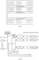
- Fig. 1 is a schematic view illustrating a structure of a depth camera provided by an embodiment of the present application.
- the depth camera includes: a processor, a plurality of light emitting elements, and at least two ToF (Time of flight) sensors.
- the composite irradiation range of the plurality of light emitting elements covers the composite field of view of the at least two ToF sensors, wherein,
- the depth camera provided in the embodiment of the present application includes at least two ToF sensors, the spatial arrangement of the ToF sensors allows them to face different field of view areas respectively, and various field of view areas can be combined to form a larger field of view area.
- the number and arrangement of the ToF sensors and light emitting elements can be determined according to actual requirements on the field of view, as long as the composite irradiation range of all the light emitting elements of the depth camera can cover the composite field of view of all the ToF sensors.
- the processor in the depth camera may obtain an external control signal through an input interface of the depth camera, the external control signal may be input by an operator to set and adjust corresponding parameters of the depth camera, for example, to set or adjust exposure time of the depth camera.
- the processor may generate, based on the external control signal, a modulation signal and a demodulation signal corresponding to the modulation signal.
- the processor transmits the modulation signal to each light emitting element, and transmits the demodulation signal to each ToF sensor, i.e., all the light emitting elements in the depth camera use the same modulation signal and all the ToF sensors in the depth camera use the same demodulation signal to synchronize the modulation and demodulation.
- the light emitting element After receiving the modulation signal transmitted by the processor, the light emitting element modulates its own light signal and transmits the modulated light signal. An object within the irradiation range of each light emitting element reflects back the modulated light signal of the light emitting element and the modulated light signal is received by a ToF sensor with the field of view range corresponding to the irradiation range.
- the ToF sensor after receiving the modulated light signal reflected back by an object within its field of view, demodulates the received modulated light signal with the demodulation signal to generate depth data.
- the depth data generated by each ToF sensor is depth value of each pixel obtained by the ToF sensor within its field of view.
- Each ToF sensor outputs the generated depth data to the processor.
- the processor After receiving depth data input by each ToF sensor, the processor performs data fusion processing on all the received depth data, and selects suitable original points for mapping the data within the composite field of view of the ToF sensors, in order to generate combined depth data and obtain a combined depth map based on the combined depth data.
- the processor outputs the obtained combined depth map through an output interface of the depth camera as output of the depth camera.
- the processor may also generate a control signal for each ToF sensor according to the received external control signal, and issue a corresponding parameter to the ToF sensor to perform corresponding control on the ToF sensor.
- the depth camera provided by the embodiment of the present application includes a processor, a plurality of light emitting elements, and at least two ToF sensors, which can meet the application requirements of a depth map of a large field of view.
- light emitting elements use the same modulation signal to modulate the light signals and then transmit the modulated light signals
- ToF sensors demodulate the received modulated light signals reflected back by objects with the same demodulation signal corresponding to the modulation signal to generate depth data.
- the problem of mutual interference due to asynchronization of modulation and demodulation can be avoided.
- the processor performs data fusion processing on all the received depth data to obtain a combined depth map.
- the at least two ToF sensors may be arranged in a sensor array that includes at least one row and at least one column;
- the spatial arrangement of the ToF sensors may be determined based on actual conditions.
- Several examples are provided in the following to illustrate the arrangement of the at least two ToF sensors contained in the depth camera.
- the plurality of ToF sensors in the depth camera When a plurality of ToF sensors in the depth camera are arranged in a sensor array that only includes one row, the plurality of ToF sensors will be arranged in the same line, and geometric centers of target surfaces of all the ToF sensors are located on this line, the distance between any two adjacent ToF sensors meets a preset first distance requirement, and the angle between target surfaces of any two adjacent ToF sensors meets a preset angle requirement, as shown in Fig. 2 .
- the angle between target surfaces of two adjacent ToF sensors in the above Example 1, may be 0, that is, the target surfaces of two adjacent ToF sensors are coplanar or parallel to each other, as shown in Fig. 3 .
- the specific arrangement of ToF sensors in each row may be the same as that in Example 1 above.
- the geometric center of the target surface of each ToF sensor in the column is located on the same line, the distance between any two adjacent ToF sensors in the column meets a preset second distance requirement, and target surfaces of any two adjacent ToF sensors in the column are coplanar or parallel to each other, as shown in Fig. 4 .
- the specific arrangement of ToF sensors in each row may be the same as that in Example 2 above, and the specific arrangement of ToF sensors in each column may be the same as that in Example 3 above, as shown in Fig. 5 .
- the preset first distance requirement, the preset second distance requirement, and the preset angle requirement can all be set and adjusted according to actual conditions, such as, according to the practical requirement of the field of view, which are not limited in the embodiments of the present application.
- the at least two ToF sensors are arranged on a preset sphere. Different ToF sensors are located at different locations on the preset sphere, as long as the practical requirement of the field of view can be satisfied.
- the ToF sensors may be mounted according to the arrangement of ToF sensors in the depth camera provided in the above embodiment of the present application by those skilled in the art. During the mounting of the ToF sensors, it is also necessary to mount light emitting elements according to the composite field of view of the ToF sensors, so that light emitted by the light emitting elements can cover the composite field of view of the ToF sensors.
- the specific arrangements of ToF sensors are not limited to those in the examples above. Those skilled in the art may derive other different examples according to the above-mentioned several examples, which will not be described in detail in the embodiments of the present application.
- the processor in the depth camera may include a control chip so that a demodulation signal can be shared by a plurality of ToF sensors and a modulation signal can be shared by a plurality of light emitting elements.
- the control chip generates a modulation signal for the light emitting elements according to the principle of ToF technology and controls light emitted by the light emitting elements with the modulation signal.
- the control chip generates a demodulation signal corresponding to the modulation signal according to the modulation signal and transmits the demodulation signal to all the ToF sensors to demodulate the modulated light signals.
- the processor may collect depth data output by a plurality of ToF sensors using one chip, which may be the control chip for generating the modulation and demodulation signals as set forth above, or another separate chip.
- the chip may perform data fusion processing on the depth data collected from a plurality of ToF sensors to obtain a combined depth map, which is the output of the depth camera in the embodiments of the present application.
- the processor may include at least one FPGA (Field Programmable Gate Array), and ToF controllers TFCs, each of which corresponds to a ToF sensor, wherein,
- TFC refers to a ToF controller, which is an ASIC chip configured to control a ToF system and process outputs of ToF sensors.
- the output of each ToF sensor contained in the depth camera will be analyzed by a corresponding TFC.
- the ToF sensor that output an analog signal needs to perform analog-digital conversion of the output and then send it to TFC.
- the demodulation signal for all the ToF sensors is generated by one of the TFCs so as to achieve demodulation synchronization, and the rest of the TFCs are only responsible for receiving depth data input by corresponding ToF sensors.
- each light emitting element is driven by an illumination circuit of the depth camera to modulate light signals to be emitted with the modulation signal from the above-mentioned TFC generating the demodulation signal.
- each light emitting element may be composed of a plurality of LEDs, and may also be composed of a plurality of laser emitters and light learning light elements.
- the depth camera uses at least one FPGA to collect the depth data output by each TFC and perform data fusion processing on all the depth data to obtain a combined depth map, which may be used as an output of the entire depth camera for external use.
- the FPGA may also receive external control signals and transmit the control signals to each TFC.
- DDR is a dual data rate synchronous dynamic random access memory, which is called: Dual Data Rate SDRAM
- Flash is a flash memory.
- the locations of various components are only for convenience of illustration and do not represent the position in the actual structure.
- depth data output by each ToF sensor is analyzed by one TFC.
- the function of the TFC may be implemented by the FPGA in order to save hardware overhead of the TFC.
- the collection, analysis, and processing etc. of depth data output by each ToF sensor which are implemented by TFCs in the embodiment shown in Fig. 6 , are all directly implemented by the FPGA. All of the modulation signal, demodulation signal and control signals are also generated by the FPGA.
- the FPGA in this embodiment may also be substituted by other processors satisfying the requirements of collection and computing resource capabilities.
- the depth camera may also include a color camera, the field of view of the color camera covers the composite field of view of the at least two ToF sensors:
- Color data can be collected with a color camera mounted in the depth camera.
- the processor may align the color data with the combined depth data, so as to obtain a color image fused with depth information, i.e., an RGB-D image, wherein, for each pixel, not only its own depth value but also its gray scale and color information are stored.
- a method for obtaining a combined depth map is also provided in embodiments of the present application, applicable to a processor of a depth camera.
- the depth camera includes the processor, a plurality of light emitting elements and at least two ToF sensors.
- the composite irradiation range of the at least one light emitting element covers the composite field of view of the at least two ToF sensors.
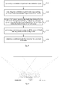
- the method includes the following steps:
- the technical solution provided in the embodiment of the present application is applicable to a processor in a depth camera.
- the depth camera includes at least two ToF sensors, the spatial arrangement of the ToF sensors allows them to face different field of view areas respectively, and various field of view areas can be combined to form a larger field of view area.
- the number and arrangement of the ToF sensors and light emitting elements can be determined according to actual requirements on the field of view, as long as the composite irradiation range of all the light emitting elements of the depth camera can cover the composite field of view of all the ToF sensors.
- the processor may generate a modulation signal and a demodulation signal corresponding to the modulation signal.
- the processor transmits the modulation signal to each light emitting element, and transmits the demodulation signal to each ToF sensor, that is, all the light emitting elements in the depth camera use the same modulation signal and all the ToF sensors in the depth camera use the same demodulation signal so that synchronization of modulation and demodulation can be achieved.
- the light emitting element After receiving the modulation signal transmitted by the processor, the light emitting element modulates its own light signal and transmits the modulated light signal. An object within the irradiation range of each light emitting element reflects back the modulated light signal of the light emitting element and the modulated light signal is received by a ToF sensor with a field of view range corresponding to the irradiation range.
- the ToF sensor after receiving the modulated light signal reflected back by an object within its field of view, demodulates the received modulated light signal with the demodulation signal to generate depth data.
- the depth data generated by each ToF sensor is depth value of each pixel obtained by the ToF sensor within its field of view.
- Each ToF sensor outputs the generated depth data to the processor.
- the processor After receiving depth data input by each ToF sensor, the processor performs data fusion processing on all the received depth data, and selects suitable original points for mapping the data within the composite field of view of the ToF sensors, in order to generate combined depth data and obtain a combined depth map based on the combined depth data.
- the processor outputs the obtained combined depth map through an output interface of the depth camera as output of the depth camera.
- a depth map of a large field of view By applying the technical solutions provided in the embodiments of the present application, application requirements of a depth map of a large field of view can be satisfied.
- light emitting elements use the same modulation signal to modulate light signals and then transmit the modulated light signals, and ToF sensors demodulate the received modulated light signals reflected back by objects with the same demodulation signal corresponding to the modulation signal to generate depth data.
- the problem of mutual interference due to asynchronization of modulation and demodulation can be avoided.
- the processor performs data fusion processing on all the received depth data to obtain a combined depth map.
- performing data fusion processing on all the received depth data to generate combined depth data in S140 may include:
- confidence degree is typically used to indicate the magnitude of the error between the depth value and the real value.
- there is a one-to-one correspondence between confidence degrees and depth values that is., each pixel in depth data output by a ToF sensor has a corresponding depth value, as well as a confidence degree.
- the ToF sensor has a confidence degree corresponding to the depth value of each original pixel. For each target pixel within the field of view overlapping area, the depth value obtained by a ToF sensor corresponding to the highest confidence degree among confidence degrees of a plurality of original pixels corresponding to the target pixel is determined as the depth value of the pixel.
- the field of view of the ToF sensor A and the ToF sensor B has an overlapping area O.
- the depth value obtained by the ToF sensor A and the depth value obtained by the ToF sensor B For each pixel in the overlapping area O, there are both the depth value obtained by the ToF sensor A and the depth value obtained by the ToF sensor B.
- the depth value obtained by the ToF sensor A is determined as the depth value of the pixel.
- Combined depth data can be generated based on the determined depth value for each pixel.
- step S140 i.e., performing data fusion processing on all the received depth data to generate combined depth data.
- a depth camera containing at least two ToF sensors is considered as a plurality of depth cameras, each of which contains a single ToF sensor.
- all the description of depth camera is directed to a depth camera of a single ToF sensor.
- the preconditions for implementing this calculation method are as follows:
- a virtual depth camera is located at the midpoint of the line connecting optical centers of two real depth cameras.
- the focal length and field of view of the virtual depth camera may be defined according to actual requirements.
- Depth data of the two real depth cameras are respectively mapped onto the virtual depth camera for fusion. During the fusion, data beyond the field of view of the virtual depth camera are discarded and data within the field of view overlapping area is selected according to confidence degrees, wherein, if there are points in the two real depth cameras mapped to the same point in the virtual depth camera, the point with a larger confidence degree is retained. As shown in Fig.
- ⁇ there is an angle ⁇ between the imaging plane of the real depth camera and the imaging plane of the virtual depth camera, and the value of ⁇ may be zero, or it may be a positive or negative value.
- the angle ⁇ between two real depth cameras can take different values, the specific values can be determined according to actual requirements.
- Correspondence between more than two real depth cameras and a virtual depth camera may be derived on the basis of Fig. 9 , the detail of which will not be repeated herein.
- Mapping relationship from the real depth cameras to the virtual depth camera is now derived in the following. During the derivation, the distortion of lens of cameras are not taken into account.
- Or is the optical center of a lens of a real depth camera
- Ov is the optical center of a lens of the virtual depth camera
- the line connecting Or and Ov, labeled as B, is parallel to the imaging plane of the virtual depth camera.
- Cartesian coordinate systems are respectively established at Or and Ov according to a front projection model for camera imaging, wherein, X-axes of the two coordinate systems are coplanar with an angle ⁇ there between, and Y-axes are parallel to each other.
- the focal length of the real depth camera is f1
- the focal length of the virtual depth camera is f2.
- the projection point of a point P in space in the coordinate system for the real depth camera is Pr, its coordinates are (x1, y1) and the corresponding depth value is d1;
- the projection point of the point P in space in the coordinate system for the virtual depth camera is Pv, its coordinates are (x2, y2) and the corresponding depth value is d2.
- the point P has the same y coordinate, denoted as yp, in the two coordinate systems.
- the projection of point P on the plane where the X-axes of the two coordinate systems are located is Po.
- the line connecting Po and Or is denoted as dr, and the line connecting Po and Ov is denoted as dv.
- the angle between dr and B is denoted as ⁇ , and the angle between dv and B is denoted as ⁇ .
- B, ⁇ , f1, f2 are constant during calculation.
- coefficients (k1, k2, k3, k4, ⁇ ) for each point (x1,y1) in the coordinate system for each real depth camera can be calculated based on parameters of each real depth camera and virtual depth camera and stored in a table, such that during subsequent mapping calculation, the coefficients can be obtained by looking up in the table and substituted for calculation. Consumption of computing resource for calculating the coefficients may thus be eliminated.
- the data fusion processing process for multiple depth data may be as follows: During the initialization of the real depth camera, the position and focal length of the virtual depth camera are firstly determined, and then the distance and tilt angle of each real depth camera with respect to the virtual depth camera are calculated based on the parameters of the virtual depth camera. Subsequently, on the basis of these determined parameters, mapping coefficients (k1, k2, k3, k4, ⁇ ) for each pixel of each real depth camera can be calculated according to the derivation process previously described and a look-up table can be generated.
- mapping function coefficient is obtained by looking up in the table to calculate the position and depth value of the mapping target point, and a combined depth map is obtained.
- a mapping target point will be discarded if the position of the point is beyond the field of view of the virtual depth camera. If there are multiple points that are mapped to the same target point at the same time, the depth value corresponding to the maximum confidence degree will be retained.
- target recognition, tracking and other algorithms can be performed on it.
- a person in an indoor environment, a person can be tracked and positioned using a combined depth map of a large field of view, or a combined depth map of a large field of view can be applied to a somatosensory game for recognition of a target motion in a game.
- performing data fusion processing on all the received depth data to generate combined depth data in S 140 may include the following steps:
- the field of view of the ToF sensor A and the ToF sensor B has an overlapping area O.
- the depth value T1 obtained by the ToF sensor A and the depth value T2 obtained by the ToF sensor B are both the depth value T1 obtained by the ToF sensor A and the depth value T2 obtained by the ToF sensor B. If T1>T2, the depth value T2 obtained by the ToF sensor B may be determined as the depth value of this pixel. It is also possible to take the average of T1 and T2 as the depth value of this pixel.
- Combined depth data can be obtained based on the determined depth value for each pixel.
- the depth camera may further include a color camera, the field of view of the color camera covers the composite field of view of the at least two ToF sensors.
- the method may include the following steps:
- Color data can be collected with a color camera mounted in the depth camera.
- the processor may align the color data with the combined depth data, so as to obtain a color image fused with depth information, i.e., an RGB-D image, wherein, for each pixel, not only its own depth value but also its gray scale and color information are stored.
Landscapes
- Engineering & Computer Science (AREA)
- Physics & Mathematics (AREA)
- General Physics & Mathematics (AREA)
- Electromagnetism (AREA)
- Remote Sensing (AREA)
- Radar, Positioning & Navigation (AREA)
- Computer Networks & Wireless Communication (AREA)
- Multimedia (AREA)
- Signal Processing (AREA)
- Computer Vision & Pattern Recognition (AREA)
- Theoretical Computer Science (AREA)
- Optics & Photonics (AREA)
- Measurement Of Optical Distance (AREA)
- Length Measuring Devices By Optical Means (AREA)
- Optical Radar Systems And Details Thereof (AREA)
Claims (10)
- Tiefenkamera, umfassend: einen Prozessor, eine Vielzahl von Licht emittierenden Elementen und wenigstens zwei ToF-Sensoren; einen Verbund-Bestrahlungsbereich der Vielzahl von Licht emittierenden Elementen, die ein Verbund-Sichtfeld der wenigstens zwei ToF-Sensoren abdecken, wobeider Prozessor ausgestaltet ist, um ein Modulationssignal und ein Demodulationssignal zu erzeugen und das Modulationssignal an jedes Licht emittierende Element auszugeben, das Demodulationssignal an jeden ToF-Sensor auszugeben und die von jedem ToF-Sensor eingegebenen Tiefendaten zu empfangen, die Datenfusions-Verarbeitung auf allen empfangenen Tiefendaten durchzuführen, um kombinierte Tiefendaten zu erzeugen und eine kombinierte Tiefenkarte basierend auf den kombinierten Tiefendaten zu erhalten;jedes Licht emittierende Element ausgestaltet ist, um ein von dem Prozessor eingegebenes Modulationssignal zu empfangen, sein eigenes Lichtsignal mit dem Modulationssignal zu modulieren und ein moduliertes Lichtsignal auf ein Objekt innerhalb seines eigenen Bestrahlungsbereichs zu übertragen;jeder ToF-Sensor ausgestaltet ist, um ein von dem Prozessor eingegebenes Demodulationssignal zu empfangen, ein moduliertes Lichtsignal zu empfangen, das von einem Objekt innerhalb seines eigenen Sichtfeldes reflektiert ist, das empfangene Lichtsignal mit dem Demodulationssignal zu demodulieren, um Tiefendaten zu erzeugen und die erzeugten Tiefendaten an den Prozessor auszugeben,dadurch gekennzeichnet, dass alle Licht emittierenden Elemente dasselbe Modulationssignal zum Modulieren von Lichtsignalen verwenden und alle ToF-Sensoren dasselbe Demodulationssignal verwenden, das dem Modulationssignal entspricht, um modulierte Lichtsignale zu demodulieren.
- Tiefenkamera gemäß Anspruch 1, wobei die wenigstens zwei ToF-Sensoren in einer Sensoranordnung angeordnet sind, die wenigstens eine Reihe oder wenigstens eine Spalte umfasst;für jede Reihe der Sensoranordnung ein geometrisches Zentrum einer Zielfläche jedes ToF-Sensors in der Reihe auf derselben Linie angeordnet ist, wobei eine Entfernung zwischen irgendeinem von zwei anliegenden ToF-Sensoren in der Reihe einer voreingestellten ersten Entfernungsanforderung genügt und ein Winkel zwischen Zielflächen von zwei anliegenden ToF-Sensoren in der Reihe einer voreingestellten Winkelanforderung genügt;für jede Spalte der Sensoranordnung ein geometrisches Zentrum einer Zielfläche jedes ToF-Sensors in der Spalte auf derselben Linie angeordnet ist, wobei eine Entfernung zwischen zwei anliegenden ToF-Sensoren in der Spalte einer voreingestellten zweiten Entfernungsanforderung genügt und Zielflächen von zwei anliegenden ToF-Sensoren in der Spalte koplanar oder parallel zueinander sind.
- Tiefenkamera gemäß Anspruch 2, wobei Zielflächen von zwei anliegenden ToF-Sensoren in jeder Reihe der Sensoranordnung koplanar oder parallel zueinander sind.
- Tiefenkamera gemäß Anspruch 1, wobei die wenigstens zwei ToF-Sensoren auf einem voreingestellten Bereich angeordnet sind und unterschiedliche ToF-Sensoren an unterschiedlichen Stellen auf dem voreingestellten Bereich angeordnet sind.
- Tiefenkamera gemäß Anspruch 1, wobei der Prozessor wenigstens ein Field Programmable Gate Array FPGA und ToF-Kontroller TFCs umfasst, von denen jedes einem ToF-Sensor entspricht, wobeidas FPGA ausgestaltet ist, um von jeden TFC eingegebene Tiefendaten zu empfangen, eine Datenfusions-Verarbeitung auf allen empfangenen Tiefendaten durchzuführen, um kombinierte Tiefendaten zu erzeugen und eine kombinierte Tiefenkarte basierend auf den kombinierten Tiefendaten zu erhalten;ein erster TFC der in dem Prozessor enthaltenen TFCs ausgestaltet ist, um ein Modulationssignal und ein Demodulationssignal zu erzeugen und das Modulationssignal an jedes Licht emittierende Element auszugeben und das Demodulationssignal an jeden ToF-Sensor auszugeben;jeder TFC der in dem Prozessor enthaltenen TFCs ausgestaltet ist, um Tiefendaten zu empfangen, die von einem dem TFC entsprechenden ToF-Sensor eingegeben sind, und die empfangenen Tiefendaten an das FPGA auszugeben.
- Tiefenkamera gemäß irgendeinem der Ansprüche 1-5, weiterhin umfassend: eine Farbkamera, das Sichtfeld der Farbkamera deckt das Verbund-Sichtfeld der wenigstens zwei ToF-Sensoren ab:Die Farbkamera ist ausgestaltet, um Farbdaten zu erfassen und die erfassten Farbdaten an den Prozessor auszugeben;Der Prozessor ist weiterhin ausgestaltet, um von der Farbkamera eingegebene Farbdaten zu empfangen und die empfangenen Farbdaten mit den kombinierten Tiefendaten auszurichten, um ein mit der Tiefeninformation fusioniertes Farbbild zu erhalten.
- Verfahren zum Erhalten einer kombinierten Tiefenkarte, die auf einen Prozessor einer Tiefenkamera anwendbar ist, wobei die Tiefenkamera den Prozessor, eine Vielzahl von Licht emittierenden Elementen und wenigstens zwei ToF-Sensoren, einen Verbund-Bestrahlungsbereich der Vielzahl von Licht emittierenden Elementen, die ein Verbund-Sichtfeld der wenigstens zwei ToF-Sensoren abdecken, umfasst, wobei das Verfahren umfasst:Erzeugen eines Modulationssignals und eines Demodulationssignals (S 110);Ausgeben des Modulationssignals an jedes Licht emittierende Element und Ausgeben des Demodulationssignals an jeden ToF-Sensor (S120);für jeden ToF-Sensor, empfangen von Tiefendaten, die von dem ToF-Sensor durch Demodulieren eines modulierten Lichtsignals, das von einem Objekt innerhalb des Sichtfeldes des ToF-Sensor (S130) reflektiert wird, mit dem Demodulationssignal erhalten wird; wobei das modulierte Lichtsignal durch ein Licht emittierendes Element mit einem Bestrahlungsbereich übertragen wird, der dem Sichtfeld des ToF-Sensors entspricht, nachdem das Licht emittierende Element sein eigenes Lichtsignal mit dem Modulationssignal moduliert;Durchführen einer Daten-Fusionsverarbeitung auf allen empfangenen Tiefendaten, um kombinierte Tiefendaten (S 140) zu erzeugen; undErhalten einer kombinierten Tiefenkarte basierend auf den kombinierten Tiefendaten (S150),dadurch gekennzeichnet, dass alle Licht emittierenden Elemente dasselbe Modulationssignal zum Modulieren von Lichtsignalen verwenden und alle ToF-Sensoren dasselbe Demodulationssignal verwenden, das dem Modulationssignal entspricht, um modulierte Lichtsignale zu demodulieren.
- Verfahren gemäß Anspruch 7, wobei das Durchführen einer Daten-Fusionsverarbeitung auf allen empfangenen Tiefendaten, um kombinierte Tiefendaten (S 140) zu erzeugen, umfasst:Bestimmen jeder überlappenden Region von Sichtfeldern der wenigstens zwei ToF-Sensoren;für jedes Pixel innerhalb jeder überlappenden Region von Sichtfeldern basierend auf einem Vertrauensgrad für das Pixel jedes der dem Pixel entsprechenden ToF-Sensoren Bestimmen eines Tiefenwertes, der von einem ToF-Sensor mit dem höchsten Vertrauensgrad als der Tiefenwert des Pixels erhalten wird; undErzeugen kombinierter Tiefendaten basierend auf dem bestimmten Tiefenwert jedes Pixels.
- Verfahren gemäß Anspruch 7, wobei das Durchführen einer Daten-Fusionsverarbeitung auf allen empfangenen Tiefendaten, um kombinierte Tiefendaten (S 140) zu erzeugen, umfasst:Bestimmen jeder überlappenden Region von Sichtfeldern der wenigstens zwei ToF-Sensoren;für jedes Pixel innerhalb jeder überlappenden Region des Sichtfeldes Bestimmen eines Tiefenwertes für das Pixel basierend auf einer Größenordnung eines Tiefenwertes für das Pixel, das von jedem ToF-Sensor erhalten wird, das dem Pixel entspricht; undErzeugen kombinierter Tiefendaten basierend auf dem bestimmten Tiefenwert jedes Pixels.
- Verfahren gemäß irgendeinem der Ansprüche 7-9, wobei die Tiefenkamera weiterhin eine Farbkamera umfasst, das Sichtfeld der Tiefenkamera das Verbund-Sichtfeld der wenigstens zwei ToF-Sensoren abdeckt, umfasst:Empfangen von von der Farbkamera eingegebenen Farbdaten; undAusrichten der empfangenen Farbdaten mit den kombinierten Tiefendaten zum Ausgeben eines mit der Tiefeninformation fusionierten Farbbildes.
Applications Claiming Priority (2)
| Application Number | Priority Date | Filing Date | Title |
|---|---|---|---|
| CN201510665910.6A CN106612387B (zh) | 2015-10-15 | 2015-10-15 | 一种组合深度图获得方法及深度相机 |
| PCT/CN2016/093546 WO2017063435A1 (zh) | 2015-10-15 | 2016-08-05 | 一种组合深度图获得方法及深度相机 |
Publications (3)
| Publication Number | Publication Date |
|---|---|
| EP3364643A1 EP3364643A1 (de) | 2018-08-22 |
| EP3364643A4 EP3364643A4 (de) | 2019-04-03 |
| EP3364643B1 true EP3364643B1 (de) | 2021-09-08 |
Family
ID=58517039
Family Applications (1)
| Application Number | Title | Priority Date | Filing Date |
|---|---|---|---|
| EP16854817.0A Active EP3364643B1 (de) | 2015-10-15 | 2016-08-05 | Verfahren zur gewinnung eines kombinierten tiefenbildes und tiefenkamera |
Country Status (4)
| Country | Link |
|---|---|
| US (1) | US10713804B2 (de) |
| EP (1) | EP3364643B1 (de) |
| CN (1) | CN106612387B (de) |
| WO (1) | WO2017063435A1 (de) |
Cited By (1)
| Publication number | Priority date | Publication date | Assignee | Title |
|---|---|---|---|---|
| TWI894668B (zh) * | 2022-11-01 | 2025-08-21 | 鈺立微電子股份有限公司 | 飛時測距系統以及飛時測距方法 |
Families Citing this family (42)
| Publication number | Priority date | Publication date | Assignee | Title |
|---|---|---|---|---|
| GB201511551D0 (en) | 2015-07-01 | 2015-08-12 | St Microelectronics Res & Dev | Photonics device |
| CN107063188A (zh) * | 2017-05-19 | 2017-08-18 | 深圳奥比中光科技有限公司 | 大视角3d视觉系统 |
| KR102476404B1 (ko) * | 2017-07-18 | 2022-12-12 | 엘지이노텍 주식회사 | ToF 모듈 및 그 ToF 모듈을 이용한 피사체 인식장치 |
| US10785400B2 (en) | 2017-10-09 | 2020-09-22 | Stmicroelectronics (Research & Development) Limited | Multiple fields of view time of flight sensor |
| CN108279421B (zh) * | 2018-01-28 | 2021-09-28 | 深圳新亮智能技术有限公司 | 带有高分辨率彩色图像的飞行时间相机 |
| CN110278679B (zh) * | 2018-03-13 | 2021-05-04 | 鸿海精密工业股份有限公司 | 感测模块及其电子装置 |
| CN110276338A (zh) * | 2018-03-13 | 2019-09-24 | 鸿海精密工业股份有限公司 | 感测模块及其电子装置 |
| CN108564614B (zh) * | 2018-04-03 | 2020-09-18 | Oppo广东移动通信有限公司 | 深度获取方法和装置、计算机可读存储介质和计算机设备 |
| CN110349196B (zh) * | 2018-04-03 | 2024-03-29 | 联发科技股份有限公司 | 深度融合的方法和装置 |
| CN110363051A (zh) * | 2018-04-10 | 2019-10-22 | 鸿海精密工业股份有限公司 | 感测模块及其电子装置 |
| US10999524B1 (en) | 2018-04-12 | 2021-05-04 | Amazon Technologies, Inc. | Temporal high dynamic range imaging using time-of-flight cameras |
| CN108965579A (zh) * | 2018-06-05 | 2018-12-07 | Oppo广东移动通信有限公司 | 基于tof摄像头实现测距的方法及其装置、终端和存储介质 |
| CN108897000B (zh) * | 2018-06-19 | 2022-02-08 | 北京旷视科技有限公司 | 一种串扰抑制方法、装置、电子设备和计算机可读介质 |
| US10674063B2 (en) * | 2018-06-20 | 2020-06-02 | Amazon Technologies, Inc. | Synchronizing time-of-flight cameras |
| US10708484B2 (en) | 2018-06-20 | 2020-07-07 | Amazon Technologies, Inc. | Detecting interference between time-of-flight cameras using modified image sensor arrays |
| CN108921888B (zh) * | 2018-07-03 | 2022-07-19 | 京东方科技集团股份有限公司 | 一种深度图像检测方法、系统及计算机可读存储介质 |
| CN108848320B (zh) * | 2018-07-06 | 2021-01-26 | 京东方科技集团股份有限公司 | 深度检测系统及其曝光时间调整方法 |
| US10681338B1 (en) | 2018-07-24 | 2020-06-09 | Amazon Technologies, Inc. | Detecting interference in depth images captured using overlapping depth cameras |
| CN109031331A (zh) * | 2018-08-07 | 2018-12-18 | 上海炬佑智能科技有限公司 | 飞行时间测距传感芯片及传感装置、电子设备 |
| CN109164456B (zh) * | 2018-09-21 | 2020-09-29 | 维沃移动通信有限公司 | 深度摄像头模组、移动终端及摄像头模组互扰处理方法 |
| US11055866B2 (en) | 2018-10-29 | 2021-07-06 | Samsung Electronics Co., Ltd | System and method for disparity estimation using cameras with different fields of view |
| CN109343079A (zh) * | 2018-10-30 | 2019-02-15 | 合肥泰禾光电科技股份有限公司 | 一种测距避障方法及避障装置 |
| CN109454669A (zh) * | 2018-11-14 | 2019-03-12 | 深圳蓝胖子机器人有限公司 | 机器人实时感知系统及具有其的感知机器人 |
| CN109544616B (zh) * | 2018-12-11 | 2021-02-26 | 维沃移动通信有限公司 | 一种深度信息确定方法和终端 |
| EP3671277A1 (de) * | 2018-12-21 | 2020-06-24 | Infineon Technologies AG | Vorrichtung und verfahren zur 3d-bildgebung |
| CN109541631B (zh) * | 2019-01-07 | 2024-09-10 | 杭州蓝芯科技有限公司 | 一种基于光飞行时间的大视场面阵探测雷达 |
| CN109963138A (zh) * | 2019-02-15 | 2019-07-02 | 深圳奥比中光科技有限公司 | 一种深度相机及图像获取方法 |
| CN114365482A (zh) | 2019-03-25 | 2022-04-15 | 华为技术有限公司 | 一种基于Dual Camera+TOF的大光圈虚化方法 |
| CN111741283A (zh) * | 2019-03-25 | 2020-10-02 | 华为技术有限公司 | 图像处理的装置和方法 |
| KR102068929B1 (ko) * | 2019-05-23 | 2020-01-21 | 박배억 | 3차원 카메라 시스템 |
| WO2020243901A1 (en) | 2019-06-04 | 2020-12-10 | Texas Instruments Incorporated | An optical time of flight sensor for navigation systems in robotic applications |
| DE102019215099B4 (de) * | 2019-10-01 | 2022-09-29 | Audi Ag | Verfahren zum Bereitstellen einer aktuellen lokalen Umgebungszustandskarte für ein Kraftfahrzeug sowie Kraftfahrzeug zum Durchführen eines derartigen Verfahrens |
| WO2021114036A1 (zh) * | 2019-12-09 | 2021-06-17 | 南昌欧菲生物识别技术有限公司 | Tof相机及电子设备 |
| KR102184210B1 (ko) * | 2019-12-26 | 2020-11-27 | 박배억 | 3차원 카메라 시스템 |
| CN111458693A (zh) * | 2020-02-01 | 2020-07-28 | 上海鲲游光电科技有限公司 | 直接测距tof分区探测方法及其系统和电子设备 |
| EP4189463A1 (de) * | 2020-12-18 | 2023-06-07 | Google LLC | Steuerbare kameraanordnung für kopfmontierte anzeigevorrichtungen |
| CN112950517B (zh) * | 2021-02-25 | 2023-11-03 | 浙江光珀智能科技有限公司 | 深度相机高动态范围深度图与灰度图的融合方法及装置 |
| CN117055541A (zh) * | 2022-05-06 | 2023-11-14 | 追觅创新科技(苏州)有限公司 | 自移动设备的控制方法、设备及存储介质 |
| CN114972468B (zh) * | 2022-05-26 | 2025-09-02 | 杭州海康机器人股份有限公司 | 一种深度图像获取方法、装置及电子设备 |
| CN117670967A (zh) * | 2022-08-26 | 2024-03-08 | 深圳市光鉴科技有限公司 | 一种快速深度重建方法、系统、设备及介质 |
| US12573066B2 (en) | 2022-11-07 | 2026-03-10 | Google Llc | Depth estimation using a single near-infrared camera and dot illuminator |
| CN116365374B (zh) * | 2023-03-23 | 2023-10-27 | 深圳市欧亚特电器设备有限公司 | 一种可远程控制的智能型配电柜及其控制方法 |
Family Cites Families (10)
| Publication number | Priority date | Publication date | Assignee | Title |
|---|---|---|---|---|
| US6580496B2 (en) | 2000-11-09 | 2003-06-17 | Canesta, Inc. | Systems for CMOS-compatible three-dimensional image sensing using quantum efficiency modulation |
| US8891067B2 (en) * | 2010-02-01 | 2014-11-18 | Microsoft Corporation | Multiple synchronized optical sources for time-of-flight range finding systems |
| CN101866056A (zh) * | 2010-05-28 | 2010-10-20 | 中国科学院合肥物质科学研究院 | 基于led阵列共透镜tof深度测量的三维成像方法和系统 |
| EP2405283B1 (de) * | 2010-07-06 | 2014-03-05 | Mechaless Systems GmbH | Optoelektronische Messanordnung mit einer Kompensationslichtquelle |
| JP5979500B2 (ja) * | 2011-04-07 | 2016-08-24 | パナソニックIpマネジメント株式会社 | 立体撮像装置 |
| JP5924978B2 (ja) * | 2012-02-28 | 2016-05-25 | キヤノン株式会社 | 画像処理装置および画像処理方法 |
| CN108345006B (zh) * | 2012-09-10 | 2022-04-08 | 广稹阿马斯公司 | 捕捉运动场景的设备、装置和系统 |
| AT513589B1 (de) | 2012-11-08 | 2015-11-15 | Bluetechnix Gmbh | Aufnahmeverfahren für zumindest zwei ToF-Kameras |
| KR102163728B1 (ko) * | 2013-12-05 | 2020-10-08 | 삼성전자주식회사 | 거리영상 측정용 카메라 및 이를 이용한 거리영상 측정방법 |
| EP4016981A3 (de) * | 2013-12-24 | 2022-09-21 | Sony Depthsensing Solutions | Time of flight kamera system |
-
2015
- 2015-10-15 CN CN201510665910.6A patent/CN106612387B/zh active Active
-
2016
- 2016-08-05 EP EP16854817.0A patent/EP3364643B1/de active Active
- 2016-08-05 US US15/767,607 patent/US10713804B2/en active Active
- 2016-08-05 WO PCT/CN2016/093546 patent/WO2017063435A1/zh not_active Ceased
Cited By (1)
| Publication number | Priority date | Publication date | Assignee | Title |
|---|---|---|---|---|
| TWI894668B (zh) * | 2022-11-01 | 2025-08-21 | 鈺立微電子股份有限公司 | 飛時測距系統以及飛時測距方法 |
Also Published As
| Publication number | Publication date |
|---|---|
| CN106612387B (zh) | 2019-05-21 |
| EP3364643A1 (de) | 2018-08-22 |
| US20180300891A1 (en) | 2018-10-18 |
| US10713804B2 (en) | 2020-07-14 |
| CN106612387A (zh) | 2017-05-03 |
| WO2017063435A1 (zh) | 2017-04-20 |
| EP3364643A4 (de) | 2019-04-03 |
Similar Documents
| Publication | Publication Date | Title |
|---|---|---|
| EP3364643B1 (de) | Verfahren zur gewinnung eines kombinierten tiefenbildes und tiefenkamera | |
| US9432593B2 (en) | Target object information acquisition method and electronic device | |
| JP6192853B2 (ja) | 超音波深度検出を使用するオプティカルフロー画像化システム及び方法 | |
| US9826217B2 (en) | System and method for adjusting a baseline of an imaging system with microlens array | |
| CN108377380B (zh) | 影像扫描系统及其方法 | |
| US20200192206A1 (en) | Structured light projector, three-dimensional camera module and terminal device | |
| CN105980928B (zh) | 使用超声波深度感测的rgb-d成像系统和方法 | |
| CN106548489A (zh) | 一种深度图像与彩色图像的配准方法、三维图像采集装置 | |
| JP2010538269A (ja) | 有形物の形状の3次元測定のためのシステム及び方法 | |
| CN113724391B (zh) | 三维模型构建方法、装置、电子设备和计算机可读介质 | |
| DE102017128369A1 (de) | Vorrichtung und verfahren zum lokalisieren eines ersten bauelements, lokalisierungsvorrichtung und verfahren zur lokalisierung | |
| WO2018028152A1 (zh) | 一种图像采集设备、虚拟现实设备 | |
| CN102466478B (zh) | 一种运动物体的距离测量系统及方法 | |
| CN115205375A (zh) | 检测目标的方法、跟踪目标的方法及装置 | |
| CN112255639A (zh) | 一种感兴趣区域深度感知传感器及深度感知传感模块 | |
| CN120411352A (zh) | 水下环境三维重建方法、装置、设备及存储介质 | |
| US20240095939A1 (en) | Information processing apparatus and information processing method | |
| WO2014033731A2 (en) | A system and method for depth estimation | |
| US20210398303A1 (en) | Three-dimensional modeling using hemispherical or spherical visible light-depth images | |
| CN108008403A (zh) | 红外激光测距装置及方法、无人机及避障方法 | |
| Ahrnbom et al. | Calibration and absolute pose estimation of trinocular linear camera array for smart city applications | |
| CN212163540U (zh) | 全向立体视觉的摄像机配置系统 | |
| KR102106890B1 (ko) | 소형통합제어장치 | |
| Vezeteu | Stereo-Camera–LiDAR Calibration for Autonomous Driving | |
| US20250155290A1 (en) | Systems and Methods for Performing Polarization Imaging |
Legal Events
| Date | Code | Title | Description |
|---|---|---|---|
| STAA | Information on the status of an ep patent application or granted ep patent |
Free format text: STATUS: THE INTERNATIONAL PUBLICATION HAS BEEN MADE |
|
| PUAI | Public reference made under article 153(3) epc to a published international application that has entered the european phase |
Free format text: ORIGINAL CODE: 0009012 |
|
| STAA | Information on the status of an ep patent application or granted ep patent |
Free format text: STATUS: REQUEST FOR EXAMINATION WAS MADE |
|
| 17P | Request for examination filed |
Effective date: 20180425 |
|
| AK | Designated contracting states |
Kind code of ref document: A1 Designated state(s): AL AT BE BG CH CY CZ DE DK EE ES FI FR GB GR HR HU IE IS IT LI LT LU LV MC MK MT NL NO PL PT RO RS SE SI SK SM TR |
|
| AX | Request for extension of the european patent |
Extension state: BA ME |
|
| DAV | Request for validation of the european patent (deleted) | ||
| DAX | Request for extension of the european patent (deleted) | ||
| A4 | Supplementary search report drawn up and despatched |
Effective date: 20190301 |
|
| RIC1 | Information provided on ipc code assigned before grant |
Ipc: G01S 17/93 20060101ALI20190225BHEP Ipc: H04N 5/225 20060101AFI20190225BHEP Ipc: G01S 17/89 20060101ALI20190225BHEP |
|
| STAA | Information on the status of an ep patent application or granted ep patent |
Free format text: STATUS: EXAMINATION IS IN PROGRESS |
|
| 17Q | First examination report despatched |
Effective date: 20200330 |
|
| REG | Reference to a national code |
Ref country code: DE Ref legal event code: R079 Ref document number: 602016063554 Country of ref document: DE Free format text: PREVIOUS MAIN CLASS: H04N0005225000 Ipc: G01S0017890000 |
|
| GRAP | Despatch of communication of intention to grant a patent |
Free format text: ORIGINAL CODE: EPIDOSNIGR1 |
|
| STAA | Information on the status of an ep patent application or granted ep patent |
Free format text: STATUS: GRANT OF PATENT IS INTENDED |
|
| RIC1 | Information provided on ipc code assigned before grant |
Ipc: H04N 5/225 20060101ALI20210324BHEP Ipc: G01S 17/894 20200101ALI20210324BHEP Ipc: G01S 17/87 20200101ALI20210324BHEP Ipc: G01S 17/93 20200101ALI20210324BHEP Ipc: G01S 17/89 20200101AFI20210324BHEP |
|
| INTG | Intention to grant announced |
Effective date: 20210415 |
|
| GRAS | Grant fee paid |
Free format text: ORIGINAL CODE: EPIDOSNIGR3 |
|
| GRAA | (expected) grant |
Free format text: ORIGINAL CODE: 0009210 |
|
| STAA | Information on the status of an ep patent application or granted ep patent |
Free format text: STATUS: THE PATENT HAS BEEN GRANTED |
|
| RAP3 | Party data changed (applicant data changed or rights of an application transferred) |
Owner name: HANGZHOU HIKVISION DIGITAL TECHNOLOGY CO., LTD. |
|
| RIN1 | Information on inventor provided before grant (corrected) |
Inventor name: PU, SHILIANG Inventor name: YU, HAI Inventor name: SHEN, LINJIE Inventor name: MAO, HUI Inventor name: WANG, JINGXIONG |
|
| AK | Designated contracting states |
Kind code of ref document: B1 Designated state(s): AL AT BE BG CH CY CZ DE DK EE ES FI FR GB GR HR HU IE IS IT LI LT LU LV MC MK MT NL NO PL PT RO RS SE SI SK SM TR |
|
| REG | Reference to a national code |
Ref country code: GB Ref legal event code: FG4D |
|
| REG | Reference to a national code |
Ref country code: AT Ref legal event code: REF Ref document number: 1429052 Country of ref document: AT Kind code of ref document: T Effective date: 20210915 Ref country code: CH Ref legal event code: EP |
|
| REG | Reference to a national code |
Ref country code: IE Ref legal event code: FG4D |
|
| REG | Reference to a national code |
Ref country code: DE Ref legal event code: R096 Ref document number: 602016063554 Country of ref document: DE |
|
| REG | Reference to a national code |
Ref country code: LT Ref legal event code: MG9D |
|
| REG | Reference to a national code |
Ref country code: NL Ref legal event code: MP Effective date: 20210908 |
|
| PG25 | Lapsed in a contracting state [announced via postgrant information from national office to epo] |
Ref country code: RS Free format text: LAPSE BECAUSE OF FAILURE TO SUBMIT A TRANSLATION OF THE DESCRIPTION OR TO PAY THE FEE WITHIN THE PRESCRIBED TIME-LIMIT Effective date: 20210908 Ref country code: SE Free format text: LAPSE BECAUSE OF FAILURE TO SUBMIT A TRANSLATION OF THE DESCRIPTION OR TO PAY THE FEE WITHIN THE PRESCRIBED TIME-LIMIT Effective date: 20210908 Ref country code: BG Free format text: LAPSE BECAUSE OF FAILURE TO SUBMIT A TRANSLATION OF THE DESCRIPTION OR TO PAY THE FEE WITHIN THE PRESCRIBED TIME-LIMIT Effective date: 20211208 Ref country code: LT Free format text: LAPSE BECAUSE OF FAILURE TO SUBMIT A TRANSLATION OF THE DESCRIPTION OR TO PAY THE FEE WITHIN THE PRESCRIBED TIME-LIMIT Effective date: 20210908 Ref country code: NO Free format text: LAPSE BECAUSE OF FAILURE TO SUBMIT A TRANSLATION OF THE DESCRIPTION OR TO PAY THE FEE WITHIN THE PRESCRIBED TIME-LIMIT Effective date: 20211208 Ref country code: HR Free format text: LAPSE BECAUSE OF FAILURE TO SUBMIT A TRANSLATION OF THE DESCRIPTION OR TO PAY THE FEE WITHIN THE PRESCRIBED TIME-LIMIT Effective date: 20210908 Ref country code: ES Free format text: LAPSE BECAUSE OF FAILURE TO SUBMIT A TRANSLATION OF THE DESCRIPTION OR TO PAY THE FEE WITHIN THE PRESCRIBED TIME-LIMIT Effective date: 20210908 Ref country code: FI Free format text: LAPSE BECAUSE OF FAILURE TO SUBMIT A TRANSLATION OF THE DESCRIPTION OR TO PAY THE FEE WITHIN THE PRESCRIBED TIME-LIMIT Effective date: 20210908 |
|
| REG | Reference to a national code |
Ref country code: AT Ref legal event code: MK05 Ref document number: 1429052 Country of ref document: AT Kind code of ref document: T Effective date: 20210908 |
|
| PG25 | Lapsed in a contracting state [announced via postgrant information from national office to epo] |
Ref country code: LV Free format text: LAPSE BECAUSE OF FAILURE TO SUBMIT A TRANSLATION OF THE DESCRIPTION OR TO PAY THE FEE WITHIN THE PRESCRIBED TIME-LIMIT Effective date: 20210908 Ref country code: GR Free format text: LAPSE BECAUSE OF FAILURE TO SUBMIT A TRANSLATION OF THE DESCRIPTION OR TO PAY THE FEE WITHIN THE PRESCRIBED TIME-LIMIT Effective date: 20211209 |
|
| PG25 | Lapsed in a contracting state [announced via postgrant information from national office to epo] |
Ref country code: AT Free format text: LAPSE BECAUSE OF FAILURE TO SUBMIT A TRANSLATION OF THE DESCRIPTION OR TO PAY THE FEE WITHIN THE PRESCRIBED TIME-LIMIT Effective date: 20210908 |
|
| PG25 | Lapsed in a contracting state [announced via postgrant information from national office to epo] |
Ref country code: IS Free format text: LAPSE BECAUSE OF FAILURE TO SUBMIT A TRANSLATION OF THE DESCRIPTION OR TO PAY THE FEE WITHIN THE PRESCRIBED TIME-LIMIT Effective date: 20220108 Ref country code: SM Free format text: LAPSE BECAUSE OF FAILURE TO SUBMIT A TRANSLATION OF THE DESCRIPTION OR TO PAY THE FEE WITHIN THE PRESCRIBED TIME-LIMIT Effective date: 20210908 Ref country code: SK Free format text: LAPSE BECAUSE OF FAILURE TO SUBMIT A TRANSLATION OF THE DESCRIPTION OR TO PAY THE FEE WITHIN THE PRESCRIBED TIME-LIMIT Effective date: 20210908 Ref country code: RO Free format text: LAPSE BECAUSE OF FAILURE TO SUBMIT A TRANSLATION OF THE DESCRIPTION OR TO PAY THE FEE WITHIN THE PRESCRIBED TIME-LIMIT Effective date: 20210908 Ref country code: PT Free format text: LAPSE BECAUSE OF FAILURE TO SUBMIT A TRANSLATION OF THE DESCRIPTION OR TO PAY THE FEE WITHIN THE PRESCRIBED TIME-LIMIT Effective date: 20220110 Ref country code: PL Free format text: LAPSE BECAUSE OF FAILURE TO SUBMIT A TRANSLATION OF THE DESCRIPTION OR TO PAY THE FEE WITHIN THE PRESCRIBED TIME-LIMIT Effective date: 20210908 Ref country code: NL Free format text: LAPSE BECAUSE OF FAILURE TO SUBMIT A TRANSLATION OF THE DESCRIPTION OR TO PAY THE FEE WITHIN THE PRESCRIBED TIME-LIMIT Effective date: 20210908 Ref country code: EE Free format text: LAPSE BECAUSE OF FAILURE TO SUBMIT A TRANSLATION OF THE DESCRIPTION OR TO PAY THE FEE WITHIN THE PRESCRIBED TIME-LIMIT Effective date: 20210908 Ref country code: CZ Free format text: LAPSE BECAUSE OF FAILURE TO SUBMIT A TRANSLATION OF THE DESCRIPTION OR TO PAY THE FEE WITHIN THE PRESCRIBED TIME-LIMIT Effective date: 20210908 Ref country code: AL Free format text: LAPSE BECAUSE OF FAILURE TO SUBMIT A TRANSLATION OF THE DESCRIPTION OR TO PAY THE FEE WITHIN THE PRESCRIBED TIME-LIMIT Effective date: 20210908 |
|
| REG | Reference to a national code |
Ref country code: DE Ref legal event code: R097 Ref document number: 602016063554 Country of ref document: DE |
|
| PLBE | No opposition filed within time limit |
Free format text: ORIGINAL CODE: 0009261 |
|
| STAA | Information on the status of an ep patent application or granted ep patent |
Free format text: STATUS: NO OPPOSITION FILED WITHIN TIME LIMIT |
|
| PG25 | Lapsed in a contracting state [announced via postgrant information from national office to epo] |
Ref country code: DK Free format text: LAPSE BECAUSE OF FAILURE TO SUBMIT A TRANSLATION OF THE DESCRIPTION OR TO PAY THE FEE WITHIN THE PRESCRIBED TIME-LIMIT Effective date: 20210908 |
|
| 26N | No opposition filed |
Effective date: 20220609 |
|
| PG25 | Lapsed in a contracting state [announced via postgrant information from national office to epo] |
Ref country code: SI Free format text: LAPSE BECAUSE OF FAILURE TO SUBMIT A TRANSLATION OF THE DESCRIPTION OR TO PAY THE FEE WITHIN THE PRESCRIBED TIME-LIMIT Effective date: 20210908 |
|
| PG25 | Lapsed in a contracting state [announced via postgrant information from national office to epo] |
Ref country code: IT Free format text: LAPSE BECAUSE OF FAILURE TO SUBMIT A TRANSLATION OF THE DESCRIPTION OR TO PAY THE FEE WITHIN THE PRESCRIBED TIME-LIMIT Effective date: 20210908 |
|
| PG25 | Lapsed in a contracting state [announced via postgrant information from national office to epo] |
Ref country code: MC Free format text: LAPSE BECAUSE OF FAILURE TO SUBMIT A TRANSLATION OF THE DESCRIPTION OR TO PAY THE FEE WITHIN THE PRESCRIBED TIME-LIMIT Effective date: 20210908 |
|
| REG | Reference to a national code |
Ref country code: CH Ref legal event code: PL |
|
| PG25 | Lapsed in a contracting state [announced via postgrant information from national office to epo] |
Ref country code: LU Free format text: LAPSE BECAUSE OF NON-PAYMENT OF DUE FEES Effective date: 20220805 Ref country code: LI Free format text: LAPSE BECAUSE OF NON-PAYMENT OF DUE FEES Effective date: 20220831 Ref country code: CH Free format text: LAPSE BECAUSE OF NON-PAYMENT OF DUE FEES Effective date: 20220831 |
|
| REG | Reference to a national code |
Ref country code: BE Ref legal event code: MM Effective date: 20220831 |
|
| P01 | Opt-out of the competence of the unified patent court (upc) registered |
Effective date: 20230424 |
|
| PG25 | Lapsed in a contracting state [announced via postgrant information from national office to epo] |
Ref country code: IE Free format text: LAPSE BECAUSE OF NON-PAYMENT OF DUE FEES Effective date: 20220805 |
|
| PG25 | Lapsed in a contracting state [announced via postgrant information from national office to epo] |
Ref country code: BE Free format text: LAPSE BECAUSE OF NON-PAYMENT OF DUE FEES Effective date: 20220831 |
|
| PG25 | Lapsed in a contracting state [announced via postgrant information from national office to epo] |
Ref country code: HU Free format text: LAPSE BECAUSE OF FAILURE TO SUBMIT A TRANSLATION OF THE DESCRIPTION OR TO PAY THE FEE WITHIN THE PRESCRIBED TIME-LIMIT; INVALID AB INITIO Effective date: 20160805 |
|
| PG25 | Lapsed in a contracting state [announced via postgrant information from national office to epo] |
Ref country code: CY Free format text: LAPSE BECAUSE OF FAILURE TO SUBMIT A TRANSLATION OF THE DESCRIPTION OR TO PAY THE FEE WITHIN THE PRESCRIBED TIME-LIMIT Effective date: 20210908 |
|
| PG25 | Lapsed in a contracting state [announced via postgrant information from national office to epo] |
Ref country code: MK Free format text: LAPSE BECAUSE OF FAILURE TO SUBMIT A TRANSLATION OF THE DESCRIPTION OR TO PAY THE FEE WITHIN THE PRESCRIBED TIME-LIMIT Effective date: 20210908 |
|
| PG25 | Lapsed in a contracting state [announced via postgrant information from national office to epo] |
Ref country code: MT Free format text: LAPSE BECAUSE OF FAILURE TO SUBMIT A TRANSLATION OF THE DESCRIPTION OR TO PAY THE FEE WITHIN THE PRESCRIBED TIME-LIMIT Effective date: 20210908 |
|
| PGFP | Annual fee paid to national office [announced via postgrant information from national office to epo] |
Ref country code: DE Payment date: 20250812 Year of fee payment: 10 |
|
| PGFP | Annual fee paid to national office [announced via postgrant information from national office to epo] |
Ref country code: GB Payment date: 20250826 Year of fee payment: 10 |
|
| PGFP | Annual fee paid to national office [announced via postgrant information from national office to epo] |
Ref country code: FR Payment date: 20250828 Year of fee payment: 10 |
|
| PG25 | Lapsed in a contracting state [announced via postgrant information from national office to epo] |
Ref country code: TR Free format text: LAPSE BECAUSE OF FAILURE TO SUBMIT A TRANSLATION OF THE DESCRIPTION OR TO PAY THE FEE WITHIN THE PRESCRIBED TIME-LIMIT Effective date: 20210908 |