EP3364647B1 - Bildverarbeitungsvorrichtung, bildverarbeitungsprogramm, bildverarbeitungsvorrichtung und bildverarbeitungsverfahren - Google Patents
Bildverarbeitungsvorrichtung, bildverarbeitungsprogramm, bildverarbeitungsvorrichtung und bildverarbeitungsverfahren Download PDFInfo
- Publication number
- EP3364647B1 EP3364647B1 EP18163870.1A EP18163870A EP3364647B1 EP 3364647 B1 EP3364647 B1 EP 3364647B1 EP 18163870 A EP18163870 A EP 18163870A EP 3364647 B1 EP3364647 B1 EP 3364647B1
- Authority
- EP
- European Patent Office
- Prior art keywords
- gradation
- image data
- processing
- conversion processing
- curve
- Prior art date
- Legal status (The legal status is an assumption and is not a legal conclusion. Google has not performed a legal analysis and makes no representation as to the accuracy of the status listed.)
- Active
Links
Images


Classifications
-
- H—ELECTRICITY
- H04—ELECTRIC COMMUNICATION TECHNIQUE
- H04N—PICTORIAL COMMUNICATION, e.g. TELEVISION
- H04N23/00—Cameras or camera modules comprising electronic image sensors; Control thereof
- H04N23/70—Circuitry for compensating brightness variation in the scene
- H04N23/71—Circuitry for evaluating the brightness variation
-
- H—ELECTRICITY
- H04—ELECTRIC COMMUNICATION TECHNIQUE
- H04N—PICTORIAL COMMUNICATION, e.g. TELEVISION
- H04N23/00—Cameras or camera modules comprising electronic image sensors; Control thereof
- H04N23/70—Circuitry for compensating brightness variation in the scene
- H04N23/76—Circuitry for compensating brightness variation in the scene by influencing the image signals
Definitions
- the present invention relates to an imaging apparatus.
- Patent Document 1 compresses a gradation by increasing a gain in the dark part gradation to improve the dark flattening of the dark part gradation.
- Patent Document 1 Japanese Patent No. 2663189 Further exemplary imaging apparatuses are known from EP 1 761 040 A2 , US 2002/047911 A1 , JP 2008 104010 A , and US 2005/280868 A1 .
- gradation conversion processing there is widely known the gradation conversion processing using a so-called S-shaped gradation curve for enhancing contrast.
- S-shaped gradation curve for enhancing contrast.
- the gradation conversion processing using this S-shaped gradation curve although capable of enhancing the contrast, sometimes degrades contrast in bright part gradation or flattens the dark part gradation darkly.
- the present invention has been made in view of the above-described problems and a proposition of the present invention is to perform image processing capable of improving the bright part gradation and the dark part gradation while maintaining the apparent contrast.
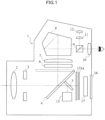
- FIG. 1 is a diagram showing a configuration of an electronic camera 1 in the first embodiment.
- the electronic camera 1 is equipped with the following respective parts, which are a photographic lens 2, an aperture diaphragm 3, a quick return mirror 4, a sub mirror 5, a diffusing screen 6, a condenser lens 7, a pentaprism 8, a beam splitter 9, an eyepiece lens 10, a imaging lens 11, a photometry sensor 12, a shutter 13, an imaging sensor 14, and a focus detecting part 1 5.
- the photometry sensor 12 is a photometry sensor having five divisions, for example.
- the imaging sensor 14 is a semiconductor device such as CCD (Charge Coupled Device) and CMOS (Complementary Metal Oxide Semiconductor), for example.
- the focus detecting part 15 performs focus detection by a phase difference method, for example, to detect a focusing state of the photographic lens 2. Further, the electronic camera 1 performs the focus detection by a contrast method according to brightness detected by the photometry sensor 12 to detect the focusing state of the photographic lens 2.
- the electronic camera 1 is further equipped with a monitor 16 such as a liquid crystal monitor displaying an image generated by imaging or the like, and a control unit 17 controlling each part.
- the control unit 17 internally includes a memory which is not shown in the drawing and records a program for controlling each part.
- the quick return mirror 4 is disposed at an angle of 45 degrees as shown in FIG. 1 . Then, a light flux having passed through the photographic lens 2 and the aperture diaphragm 3 is reflected by the quick return mirror 4 and guided to the eyepiece lens 10 via the diffusing screen 6, the condenser lens 7, the pentaprism 8 and the beam splitter 9. A user performs the confirmation of composition by viewing an object image via the eyepiece lens 10. Meanwhile, a light flux split in the upper direction by the beam splitter 9 is re-imaged on an imaging plane of the photometric sensor 12 via the imaging lens 11. Further, the light flux having passed through the quick return mirror 4 is guided to the focus detecting part 15 via the sub mirror 5.
- the quick return mirror 4 recedes to a position shown in a broken line and the shutter 13 is released, and then the light flux from the photographic lens 2 is guided to the imaging sensor 14.
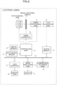
- FIG. 2 is a functional block diagram of the electronic camera 1 of the first embodiment.
- the electronic camera 1 in addition to the configuration of FIG. 1 , is equipped with the following respective parts, which are a timing generator 20, a signal processing part 21, an A/D converting part 22, a buffer memory 23, a bus 24, a card interface 25, a compression/extension part 26, and an image displaying part 27.
- the timing generator 20 supplies an output pulse to the imaging sensor 14.
- the image data generated by the imaging sensor 14 is temporarily stored in the buffer memory 23 via the signal processing part 21 (including a gain adjusting part corresponding to imaging sensitivity) and the A/D converting part 22.
- the buffer memory 23 is connected to the bus 24.
- This bus 24 is connected with the card interface 25, the controlling unit 17 explained in FIG. 1 , the compression/extension part 26, and the image displaying part 27.
- the card interface 25 is connected with a detachable memory card 28 and records the image data into the memory card 28.
- the controlling unit 17 is connected with a switch group 29 of the electronic camera 1 (including a release button and the like which are not shown in the drawing), the timing generator 20 and the photometry sensor 12.
- the image displaying part 27 displays an image and the like on the monitor 16 provided on the back plane of the electronic camera 1.
- the electronic camera 1 is equipped with a gradation non-compression mode without performing the correction of the dark part gradation in the image data and a gradation compression mode performing the correction of the dark part gradation.
- mode the photographing is to be carried out is preliminarily selected by the user via the switch group 29 or is automatically selected by the controlling unit 17.
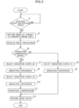
- Photographing operation of the electronic camera 1 configured as explained above will be explained by the use of a flowchart shown in FIG. 3 .
- Step S1 the controlling unit 17 determines whether the instruction of photographing start has been provided by a user via the switch group 29. Then, when the controlling unit 17 determines that the instruction of the photographing start has been provided, the controlling unit 17 goes to Step S2.
- Step S2 the controlling unit 17 controls each part, and causes the imaging sensor 14 to capture an object image and generate image data.
- the image data generated in the imaging sensor 14 is temporarily stored in the buffer memory 23 via the signal processing part 21 and the A/D converting part 22.
- Step S3 the controlling unit 17 reads out the image data from the buffer memory 23 and performs normal image processing.
- the normal image processing includes white balance adjustment, interpolation processing, color correction processing, and the like.
- the specific method of each kind of the processing is the same as that of a publicly known technique and explanation will be omitted.
- Step S4 the controlling unit 17 determines whether the gradation compression mode is set or not. Then, the controlling unit 17 goes to Step S7 to be described hereinafter when the gradation compression mode is determined to be set. On the other hand, when the controlling unit 17 determines that the gradation compression mode is set (gradation non-compression mode is set), the controlling unit 17 goes to Step S5.
- Step S5 the controlling unit 17 selects a gradation curve G1.
- the gradation curve is used in gradation conversion processing which is to be performed in following Step S6.
- the controlling unit 17 preliminarily records three kinds of gradation curve (G1 to G3) shown in FIG. 4 and FIG. 5 in an internal memory which is not shown in the drawing.
- the controlling unit 17 selects the gradation curve G1 shown in FIG. 4 .
- the gradation curve G1 is a gradation curve used in normal gradation processing the same as that used in a publicly known technique.
- Step S6 the controlling unit 17 performs the gradation conversion processing for the image data subjected to the image processing in Step S3, according to the gradation curve G1 selected in Step S5. Details of the gradation conversion processing are the same as those of a publicly known technique and thus, the explanation will be omitted. Then, the controlling unit 17 goes to Step S12.
- Step S7 the controlling unit 17 selects the gradation curve G2.
- the gradation curve G2 has a characteristic realizing a low output level for the same level input when compared to the above gradation curve G1, as shown in FIG. 4 .
- the gradation curve G2 has a characteristic realizing a low output level for an input level in a dark part of a gradation when compared to the above gradation curve G1. Accordingly, the gradation curve G2 has a more gradual slope than the gradation curve G1 in the dark part of the gradation when compared to the above gradation curve G1.
- the gradation curve G2 has a characteristic which enhances contrast in a bright part of the gradation more than the above gradation curve G1. Accordingly, the gradation curve G2 has a steeper slope than the gradation curve G1 in the bright part of the gradation when compared to the above gradation curve G1.
- Step S8 the controlling part 17 performs the gradation conversion processing for the image data subjected to the image processing in Step S3, according to the gradation curve G2 selected in Step S7. Details of the gradation conversion processing are the same as those of the publicly known technique and thus, the explanation will be omitted.
- Step S9 the controlling unit 17 selects the gradation curve G3 shown in FIG. 5 .
- the gradation curve G3 has a characteristic reducing the contrast in a middle part of the gradation when compared to a one-to-one input-output relationship (refer to a dotted line in FIG. 5 ) as shown in FIG. 5 .
- Step S10 the controlling unit 17 performs the second gradation conversion processing for the image data subjected to the first gradation conversion processing in Step S8, according to the gradation curve G3 selected in Step S9. Details of the gradation conversion processing are the same as those of the publicly known technique and explanation will be omitted. Note that, by performing the gradation conversion processing according to the above gradation curve G3, the gradation is caused to become softer in the middle part of the gradation.
- Step S11 the controlling unit 17 performs the gradation compression processing for the image data subjected to the second gradation conversion processing in Step S10.
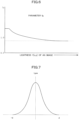
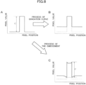
- FIG. 6 is a diagram showing a gradation compression parameter fg.
- the parameter fg has a gain according to lightness Y of an image as shown in FIG. 6 . Then, the parameter fg become larger as the smaller the lightness Y is smaller (as a periphery region including a pixel to be processed is darker). Adversely, the parameter fg comes closer to 1 as the lightness Y is larger (as the periphery region including the pixel to be processed is brighter).
- Y in Formula 1 represents a brightness value of a pixel of interest.
- kr, kg, kb, in Formula 1 are predetermined coefficients.
- Lpw in Formula 2 is a low pass filter around the pixel of interest and this low pass filter has a characteristic shown in FIG. 7 .
- ky in Formula 2 is a predetermined adjustment coefficient.
- fg in Formula 3 to Formula 5 corresponds to the above parameter fg.
- the adjustment coefficient ky is an adjustment coefficient for adjusting the contrast at a local region in an image (hereinafter, called "local contrast").
- local contrast an adjustment coefficient for adjusting the contrast at a local region in an image
- the change of ky causes a weight to change in the combining of the brightness value of the pixel of interest and a low pass value around the pixel of interest.
- the adjustment coefficient ky is equal to one, only the brightness value of the pixel of interest decides an improvement amount of the parameter fg according to Formula 3 to Formula 5.
- the adjustment coefficient ky is equal to zero, only the low pass value around the pixel of interest decides the improvement amount of the parameter fg according to Formula 3 to Formula 5.
- the local contrast tends to be reduced as the adjustment coefficient ky becomes larger, and the local contrast tends to be enhanced as the adjustment coefficient becomes smaller.
- the adjustment coefficient ky may be a fixed value or may be a variable value.
- the adjustment coefficient ky is assumed to be a fixed value of approximately 0.5, for example.
- FIG. 8 is an exemplary diagram showing the behavior of the brightness value in the periphery of a certain pixel of interest. As shown in FIG. 8 , when an original image A is subjected to processing of picking up a dark part by the gradation curve for an original image A, the contrast is reduced while dark flattening of the dark part gradation of an image B after the processing can be improved.
- Step S12 the controlling unit 17 records the image data subjected to the gradation compression processing in Step S11 or the image data subjected to the gradation conversion processing in Step S6 into the memory card 28 via the card interface 25, and completes the series of processing.
- the image data may be subjected to image compression processing (JPEG compression processing or the like) as needed via the compression/extension part 26 before recorded into the memory card 28.
- the first embodiment has the selectable first photographing mode without performing the correction of the dark gradation of the mage data and the selectable second photographing mode performing the correction of the dark gradation, and performs the gradation conversion processing according to the first input-output characteristic when the first photographing mode has been selected and performs the gradation conversion processing according to the second input-output characteristic which has a characteristic realizing a lower output level than the first input-output characteristic for the same level input and which also has a characteristic changing the contrast, when the second photographing mode has been selected.
- the first embodiment performs the correction to improve the lightness of the dark gradation in the image data subjected to the gradation conversion processing according to the second input-output characteristic by the gradation conversion processing part. Accordingly, it is possible to perform the gradation conversion processing and the correction of the dark part gradation which are capable of improving the bright part gradation and the dark part gradation while maintaining the apparent contrast in a region of interest. Further, the first embodiment can alleviate a phenomenon that a hue is changed by the gradation conversion processing using the conventional S-shaped gradation curve.
- the characteristic changing the contrast has a characteristic reducing the contrast in the middle part of the gradation. Accordingly, it is possible to suppress the result of the gradation conversion processing to a dark side and to maintain the brightness of the whole image at the same level before and after the gradation compression processing.
- the first embodiment obtains the adjustment degree of the local contrast representing the contrast in a local region of an image according to the characteristic changing the contrast in the second output characteristic and decides the lightness improvement amount according to the obtained adjustment degree. Accordingly, even if the gradation is caused to be softer by the gradation conversion processing, the dark part gradation can be corrected such that the apparent contrast is maintained at the same level in a region of interest.
- the gradation conversion processing may be configured to be performed only once by using a single gradation curve which has the characteristic realizing a lower output level than G1 for the same level input and also has the characteristic changing the contrast. That is, as shown in a flowchart of FIG. 9 , the controlling unit 17 performs the same processing in Step S21 to Step S26 as that in Step S1 to Step S6 in the flowchart of FIG. 3 .
- Step S27 the controlling unit 17 selects a gradation curve G4.
- the gradation curve G4 is a gradation curve having both the characteristic of the gradation curve G2 and the characteristic of the gradation curve G3 explained by the use of the flowchart of FIG. 3 , as shown in FIG. 10 .
- Step S28 the controlling unit 17 performs the gradation conversion processing for the image data subjected to the image processing in Step S23, according to the gradation curve G4 selected in Step S27.
- Step S29 and Step S30 the controlling unit 17 performs the same processing as that in Step S11 and Step S12 of the flowchart of FIG. 3 .
- the controlling unit 17 performs the same processing as that in Step S11 and Step S12 of the flowchart of FIG. 3 .
- the gradation curve G3 which is a gradation curve to be used for the gradation conversion processing in the gradation compression mode, and the local contrast adjustment coefficient ky are fixed
- the gradation curve G3 and the adjustment coefficient ky may be configured to be changed in conjunction with each other.
- the local contrast is reduced as the adjustment coefficient ky becomes larger, and the local contrast is enhanced as the adjustment coefficient ky becomes smaller.
- the gradation curve G3 may be set so as to strengthen the contrast in the middle part of the gradation as the adjustment coefficient ky becomes larger and the gradation curve G3 may be set so as to weaken the contrast in the middle part of the gradation as the adjustment coefficient ky becomes smaller.
- FIG. 11 shows an example of the gradation curve G3 when the adjustment coefficient ky is changed.
- the gradation curve G3 and the adjustment coefficient ky may be configured to be changed depending on a photographing mode (e.g., "portrait mode", "landscape mode” or the like), and may be configured to be changed according to a contrast strength of an image, or may be configured to be changed depending on an image adjustment mode. Further, the gradation curve G3 and the adjustment coefficient ky may be configured to be changed according to an image determination result by scene analysis or face recognition. By changing appropriately the gradation curve G3 and the adjustment coefficient ky in this manner, it is possible to perform the gradation conversion processing and the correction of the dark part gradation which are optimized for an image.
- a photographing mode e.g., "portrait mode", "landscape mode” or the like
- the gradation curve G3 and the adjustment coefficient ky may be configured to be changed according to an image determination result by scene analysis or face recognition.
- any gradation curve may be selected for the use from preliminarily recorded curves, or the controlling unit 17 may be configured to adjust the gradation curve optionally for the use.
- the first embodiment may be configured to change the gradation curve used for the gradation conversion processing according to an influence of exposure correction. For example, when the exposure correction can realize that the brightness of the whole image is maintained to some extent, the change amount of the gradation curve used in the gradation compression mode may be determined to be smaller.
- the image processing apparatus explained in the first embodiment may be realized in a software manner by a computer and an image processing program.
- a part of or the whole of the processing in Step S4 and succeeding Steps explained in the flowchart of FIG. 3 may be configured to be realized by the computer.
- a part of or the whole of the processing in Step S24 and succeeding Steps explained in the flowchart of FIG. 9 may be configured to be realized by the computer.
- information on whether the mode is the gradation compression mode or not may be supplied to the computer together with the image data. Such information can be supplied by the utilization of the EFIX information of the image data.
- a configuration of the electronic camera in the second embodiment is the same as that of the electronic camera 1 in the first embodiment. Accordingly, explanation hereinafter will be made by the use of the same symbol as that of the first embodiment. Note that the electronic camera 1 of the second embodiment does not perform the gradation compression processing explained in the first embodiment, and is not provided with the gradation non-compression mode and the gradation compression mode.
- the photographing operation of the electronic camera 1 of the second embodiment will be explained by the use of a flowchart shown in FIG. 12 .
- Step S31 the controlling unit 17 determines whether the instruction of photographing start has been provided or not by a user via the switch group 29. Then, the controlling unit 17 goes to Step S32 when the instruction of the photographing start is determined to have been provided.
- Step S32 the controlling unit 17 controls each part, causes the imaging sensor 14 to capture an object image, and generates image data.
- the image data generated by the imaging sensor 14 is temporarily stored in the buffer memory 23 via the signal processing part 21 and the A/D converting part 22.
- Step S33 the controlling unit 17 reads out the image data from the buffer memory 23 and performs the normal image processing.
- the normal image processing includes white balance adjustment, interpolation processing, color correction processing, and the like.
- the specific method of each kind of the processing is the same as that of the publicly known technique and thus, the explanation will be omitted.
- Step S34 the controlling unit 17 selects a gradation curve G5.
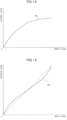
- the gradation curve G5 is used in the gradation conversion processing to be performed in Step S35 described hereinafter, and is a gradation curve in which the publicly known S-shaped characteristic is imparted to a gradation curve corresponding to an output device such as a CRT.
- the controlling unit 17 preliminarily records two kinds of gradation curve (G5 and G6) shown in FIG. 13 and FIG. 14 , respectively, in the internal memory which is not shown in the drawing.
- Step S35 the controlling unit 17 performs the gradation conversion processing for the image data subjected to the image processing in Step S33, according to the gradation curve selected in Step S34. Details of the gradation conversion processing are the same as those of the publicly known technique and thus, the explanation will be omitted.
- Step S36 the controlling unit 17 select the gradation curve G6.
- the gradation curve G6 has a characteristic weakening the contrast in the middle part of the gradation as shown in FIG. 14 , compared to a one-to-one input-output relationship (refer to a dotted line in FIG. 14 ).
- Step S37 the controlling unit 17 performs the second gradation conversion processing for the image data subjected to the first gradation conversion processing in Step S35, according to the gradation curve G6 selected in Step S36.
- Details of the gradation conversion processing are the same as those of the publicly known technique and thus, the explanation will be omitted. Note that the gradation is caused to become softer in the middle part of the gradation by the gradation conversion processing according to the above gradation curve G6.
- Step S38 the controlling unit 17 performs local contrast enhancement processing for the image data subjected to the second gradation conversion processing in Step S37.
- the local contrast is the contrast in a local region of an image.
- Y in Formula 6 represents a brightness value of a pixel of interest.
- kr, kg, and kb are predetermined coefficients.
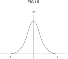
- Lpw in Formula 7 is a low pass filter around the pixel of interest, and this low pass filter has a characteristic shown in FIG. 15 .
- This low pass filter is a wide filter having a half bandwidth (d in FIG. 15 ) wider than one hundredth of a short side of an image. Accordingly, Ylp in Formula 7 corresponds to a low pass value obtained by subjecting the brightness value Y to the low pass processing.
- gain in Formula 8 is a gain in the enhancement calculation and Kdif in Formula 8 is a predetermined adjustment coefficient.
- the adjustment coefficient Kdif is a coefficient for adjusting the local contrast.
- the change of the adjustment coefficient Kdif causes a weight to change in the combining of the brightness value of the pixel of interest and the low pass value around the pixel of interest.
- the adjustment coefficient Kdif is equal to zero, the local contrast is not enhanced as apparent from Formula 8.
- the enhancement degree of the local contrast tends to become larger as the adjustment coefficient Kdif becomes larger.
- the adjustment coefficient Kdif may be a fixed value or variable value.
- the adjustment coefficient Kdif is assumed to be a fixed value of approximately 0.1, for example.
- Step S39 the controlling unit 17 records the image data subjected to the local contrast enhancement processing in Step S38 into the memory card 28 via the card interface 25, and completes the series of processing.
- the image data may be subjected to the image compression processing (JPEG compression processing or the like) as needed via the compression/extension part 26 before being recorded into the memory card 28.
- JPEG compression processing JPEG compression processing or the like
- the second embodiment performs the gradation conversion processing for the image data to be processed, according to the predetermined input-output characteristic, and performs the correction enhancing the local contrast for the image data subjected to the gradation conversion processing, according to the predetermined enhancement degree corresponding to the input characteristic. Accordingly, it is possible to improve the bright part gradation and the dark part gradation while maintaining the contrast. Further, the second embodiment can alleviate the phenomenon that respective hues in the bright part gradation, the middle part gradation and the dark part gradation are changed by the gradation conversion processing using the conventional S-shaped gradation curve.
- the second embodiment performs the correction which enhances the local contrast by using the low pass filter having a half bandwidth illustrated in FIG. 5 (d in FIG. 15 ) being one hundredth or more of a short side of an image, and thereby can perform the correction based on a medium frequency component.
- This correction is different from a correction based on a high frequency component such as edge enhancement normally performed for each pixel and can improve the bright part gradation and the dark pat gradation while maintaining the contrast by correcting the local contrast.
- the third embodiment is a variation example of the second embodiment and thus, only a different point from the second embodiment will be explained.
- a configuration of an electronic camera of the third embodiment is the same as that of the electronic camera 1 in the second embodiment. Accordingly, explanation hereinafter will be made by the use of the same symbol as that of the second embodiment.
- the controlling unit 17 may set the gradation curve G6 so that the contrast becomes weaker in the middle part of the gradation as the adjustment coefficient Kdif becomes larger.
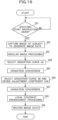
- a flowchart in FIG. 16 shows the photographing operation of an electronic camera 1 in the third embodiment.
- Step S51 to Step S55 the controlling unit 17 performs the same processing as that in Step S31 to Step S35 of the flowchart in FIG. 12 .
- Step S56 the controlling unit 17 selects the gradation curve G6 and decides the adjustment coefficient Kdif.
- the controlling unit 17 may be configured to perform the selection of the gradation curve G6 and the decision of the adjustment coefficient Kdif, depending on the photographing mode (e.g., "portrait mode", “landscape mode”, or the like), may be configured to perform these according to the contrast strength of an image, or may be configured to perform these, depending on the image adjustment mode. Further, the controlling unit 17 may be configured to perform the selection of the gradation curve G6 and the decision of the adjustment coefficient Kdif, according to an image determination result by scene analysis or face recognition. By performing appropriately the selection of the gradation curve G6 and the decision of the adjustment coefficient Kdif in this manner, it is possible to perform the gradation conversion processing and the enhancement processing of the local contrast, which are optimized for an image.
- the photographing mode e.g., "portrait mode", "landscape mode”, or the like
- the controlling unit 17 may perform the selection of the gradation curve G6 and the decision of the adjustment coefficient Kdif, according to user operation via the switch group 29.
- the controlling unit 17 causes the image displaying part 27 to display a designation screen designating a characteristic at the time of the image processing as shown in FIG. 17 .
- a user designates the characteristic at the time of the image processing by sliding a slide bar via the switch group 29. While an example shown in FIG. 17 makes use of a word "hard” or "natural", this is an example and any word may be used if the word represents the characteristic at the time of the image processing corresponding to the above gradation curve G6 and adjustment coefficient Kdif.
- the controlling unit 17 decides the input-output characteristic to be used for the gradation conversion processing and the enhancement degree in performing the correction to enhance the local contrast representing the contrast in the local region of an image, in association with each other according to the characteristic of the image processing designated by the user.
- the example of FIG. 17 decides the value of the adjustment coefficient Kdif so as to become larger as the characteristic designated by the user is closer to "natural, and decides the adjustment coefficient Kdif so as to become smaller as the characteristic designated by the user is closer to "hard”.
- the controlling unit 17 may be configured to provide a preview screen as illustrated in FIG. 17 and allow the user to confirm the result of the image processing according to the designated characteristic.
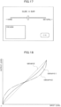
- FIG. 18 shows an example of a relationship between the gradation curve G6 and the adjustment coefficient Kdif.
- the controlling unit 17 may preliminarily record plural gradation curves as shown in FIG. 18 and select and use any of the gradation curves, or may be configured to adjust the gradation curve appropriately for the use.
- Step S57 the controlling unit 17 performs the second gradation conversion processing for the image data subjected to the first gradation conversion in Step S55, according to the gradation curve G6 selected in Step S56, in the same way as in Step 37 of the flowchart in FIG. 12 .
- Step S58 the controlling unit 17 performs the local contrast enhancement processing for the image data subjected to the second gradation conversion processing in Step S57, according to the adjustment coefficient Kdif decided in Step S56, in the same way as in the Step S38 of the flowchart in FIG. 12 .
- Step S59 the controlling unit 17 records the image data subjected to the local contrast enhancement processing in Step S58 into the memory card 28 via the card interface 25 in the same way as in Step S39 of the flowchart in FIG. 12 and completes the series of processing.
- the image data may be subjected to the image compression processing (JPEG compression processing or the like) via the compression/extension part 26 as needed before recorded into the memory card 28.
- the third embodiment decides the input-output characteristic to be used for the gradation conversion processing and the enhancement degree in performing the correction enhancing the local contrast which represents the contrast in the local region of an image, in association with each other. Accordingly, in addition to the effect of the second embodiment, it is possible to decide most appropriate factors in a balanced manner for improving the bright part gradation and the dark part gradation while maintaining the apparent contrast. Such an effect can be obtained because the human visual perception senses the contrast locally.
- the fourth embodiment is a variation example of the second embodiment and only a different point from the second embodiment will be explained.
- a configuration of an electronic camera of the fourth embodiment is the same as that of the electronic camera 1 in the second example. Accordingly, explanation hereinafter will be made by the use of the same symbol as that in the second example.
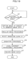
- a flowchart in FIG. 19 shows the photographing operation of the electronic camera 1 of the fourth example.
- Step S71 to Step S73 the controlling unit 17 performs the same processing as that in Step S31 to Step S33 of the flowchart in FIG. 12 .
- Step S74 the controlling unit 17 selects a gradation curve G7.
- the gradation curve G7 is a gradation curve having both the characteristic of the gradation curve G5 and the characteristic of the gradation curve G6 which have been explained by the use of the flowchart in FIG. 12 , as shown in FIG. 20 .
- Step S75 the controlling unit 17 performs the gradation conversion processing for the image data subjected to the image processing in Step S73, according to the gradation curve G7 selected in Step S74. That is, the controlling unit 17 performs the first gradation conversion processing only once by using a single gradation curve in which a characteristic weakening the contrast (corresponding to G6) is added to the normal characteristic (corresponding to G5).
- Step S76 and Step S77 the controlling unit 17 performs the same processing as that in Step S38 and Step S39 in the flowchart of FIG. 12 .
- the controlling unit 17 performs the same effect as that of the second example.
- the image processing apparatus explained in the above second example to fourth example may be realized in a software manner by a computer and an image processing program.
- a part of or the whole of the processing in Step S34 and succeeding Steps explained in the flowchart of FIG. 12 may be configured to be realized by the computer.
- a part of or the whole of the processing of Step S54 and succeeding Steps explained in the flowchart of FIG. 16 may be configured to be realized by the computer.
- a part of or the whole of the processing of Step S74 and succeeding Steps explained in the flowchart of FIG. 19 may be configured to be realized by the computer.
- the present invention can also be applied similarly to the case where the image to be processed is an image which has been subjected to the gradation conversion processing using the gradation curve G5 explained in the above second example to fourth example.
- a part of or the whole of the processing of Step S36 and succeeding Steps explained in the flowchart of FIG. 12 may be configured to be realized by the computer.
- a part of or the whole of the processing of Step S56 and succeeding Steps explained in the flowchart of FIG. 16 may be configured to be realized by the computer.
- the present invention is not limited to this example.
- the present invention can be applied similarly to a compact type electronic camera, a movie camera photographing a moving image, and the like.
Landscapes
- Engineering & Computer Science (AREA)
- Multimedia (AREA)
- Signal Processing (AREA)
- Image Processing (AREA)
- Facsimile Image Signal Circuits (AREA)
- Picture Signal Circuits (AREA)
- Studio Devices (AREA)
Claims (6)
- Bildgebungsvorrichtung (1), welche aufweist:einen Bildgebungssensor (14), welcher ein Bild eines Objekts aufnimmt und welcher Bilddaten erzeugt;ein Schaltelement (29), um einen Nutzer zu veranlassen, einen eines ersten Modus, welcher keine Korrektur der Dunkelteilgradation der vom Bildgebungssensor (14) erzeugten Bilddaten des Objekts durchführt, und eines zweiten Modus, welcher eine Korrektur der Dunkelteilgradation der Bilddaten durchführt, auszuwählen;eine Steuereinheit (17),(a) welche einen Schritt a, welcher eine erste Gradationsumwandlungsverarbeitung unter Verwendung einer ersten Gradationskurve (G1) aufweist, welche eine erste Eingabe-Ausgabe-Charakteristik hat, an den Bilddaten durchführt, wenn der erste Modus von dem Nutzer unter Verwendung des Schaltelements (29) ausgewählt ist,(b) welche einen Schritt b, welcher eine zweite Gradationsumwandlungsverarbeitung unter Verwendung einer zweiten Gradationskurve (G2, G3; G4) aufweist, welche eine zweite Eingabe-Ausgabe-Charakteristik hat, die sich von der ersten Eingabe-Ausgabe-Charakteristik unterscheidet, an den Bilddaten durchführt, wenn der zweite Modus von dem Nutzer unter Verwendung des Schaltelements (29) ausgewählt ist,(c) welche einen Schritt c, welcher eine dritte Gradationsumwandlungsverarbeitung aufweist, nachdem der zweite Gradationsumwandlungsvorgang durchgeführt ist, wobei die dritte Gradationsumwandlungsverarbeitung eine dritte Eingabe-Ausgabe-Charakteristik hat, die sich von der ersten und der zweiten Eingabe-Ausgabe-Charakteristik unterscheidet, an den Bilddaten durchführt, für welche der zweite Gradationsumwandlungsvorgang durchgeführt ist, wobei die zweite Eingabe-Ausgabe-Charakteristik eine Charakteristik aufweist, die für einen gleichen Eingabepegel in der Dunkelteilgradation einen Ausgabepegel erzielt, der niedriger ist als die erste Eingabe-Ausgabe-Charakteristik, und wobei die dritte Eingabe-Ausgabe-Charakteristik eine Charakteristik zum Kontrast-Reduzieren in einem Mittelteil der Gradation hat;welche eine Tiefpassfiltern-Verarbeitung an den Bilddaten (Y), an denen die erste Gradationsumwandlungsverarbeitung durchgeführt ist, nicht durchführt und welche eine Tiefpassfiltern-Verarbeitung an den Bilddaten (Y) durchführt, an denen die zweite Gradationsumwandlungsverarbeitung und die dritte Gradationsumwandlungsverarbeitung durchgeführt sind, und welche gefilterte Bilddaten (Y2) erzeugt; undwelche eine Gradationskompressionsverarbeitung, um eine Luminanz in der Dunkelteilgradation zu erhöhen, an den Bilddaten nicht durchführt, an denen die erste Gradationsumwandlungsverarbeitung durchgeführt ist, und welche eine Gradationskompressionsverarbeitung basierend auf einem Gradationskompressionsparameter (fg), der aus den gefilterten Bilddaten (Y2), an denen die Tiefpassfiltern-Verarbeitung durchgeführt wurde, mittels der Steuereinheit (17) berechnet ist, um eine Luminanz in der Dunkelteilgradation zu erhöhen, an den Bilddaten durchführt, an denen die zweite Gradationsumwandlungsverarbeitung und die dritte Gradationsumwandlungsverarbeitung durchgeführt sind.
- Bildgebungsvorrichtung (1) gemäß Anspruch 1, wobei
die zweite Gradationskurve (G2, G3; G4) eine graduellere Steigung als die erste Gradationskurve (G1) in der Dunkelteilgradation hat und eine steilere Steigung als die erste Gradationskurve (G1) in einer Hellteilgradation hat. - Bildgebungsvorrichtung (1) gemäß Anspruch 1 oder 2, wobei
die zweite Gradationskurve (G2, G3; G4) eine Charakteristik hat, welche einen Kontrast stärker reduziert als die erste Gradationskurve (G1) in einer
Mittelteilgradation zwischen der Dunkelteilgradation und der Hellteilgradation. - Bildgebungsvorrichtung (1) gemäß Anspruch 3, wobei
eine Steigung der zweiten Gradationskurve (G2, G3; G4) in Abhängigkeit von einem eingestellten Fotografieren-Modus geändert ist. - Bildgebungsvorrichtung (1) gemäß irgendeinem der Ansprüche 1 bis 4, wobei
die Steuereinheit (17) eine Weißabgleicheinstellungsverarbeitung vor dem Durchführen der ersten Gradationsumwandlungsverarbeitung an den Bilddaten durchführt, wenn der erste Modus mittels des Bedienelements ausgewählt ist, und die Weißabgleicheinstellungsverarbeitung vor dem Durchführen der zweiten Gradationsumwandlungsverarbeitung an den Bilddaten durchführt, wenn der zweite Modus mittels des Bedienelements ausgewählt ist. - Bildgebungsvorrichtung (1) gemäß irgendeinem der Ansprüche 1 bis 5, wobei
die Steuereinheit (17) eine Interpolationsverarbeitung vor dem Durchführen der ersten Gradationsumwandlungsverarbeitung an den Bilddaten durchführt, wenn der erste Modus mittels des Bedienelements ausgewählt ist, und die Interpolationsverarbeitung vor dem Durchführen der zweiten Gradationsumwandlungsverarbeitung an den Bilddaten durchführt, wenn der zweite Modus mittels des Bedienelements ausgewählt ist.
Applications Claiming Priority (4)
| Application Number | Priority Date | Filing Date | Title |
|---|---|---|---|
| JP2008186091A JP4941424B2 (ja) | 2008-07-17 | 2008-07-17 | 撮像装置および画像処理プログラム |
| JP2008194851A JP4883057B2 (ja) | 2008-07-29 | 2008-07-29 | 画像処理プログラム、画像処理装置、および画像処理方法 |
| EP09797655A EP2299695A4 (de) | 2008-07-17 | 2009-06-16 | Bildgeberanordnung, bildverarbeitungsprogamm, bildverarbeitungsanordnung und bildverarbeitungsverfahren |
| PCT/JP2009/002736 WO2010007726A1 (ja) | 2008-07-17 | 2009-06-16 | 撮像装置、画像処理プログラム、画像処理装置、および画像処理方法 |
Related Parent Applications (1)
| Application Number | Title | Priority Date | Filing Date |
|---|---|---|---|
| EP09797655A Division EP2299695A4 (de) | 2008-07-17 | 2009-06-16 | Bildgeberanordnung, bildverarbeitungsprogamm, bildverarbeitungsanordnung und bildverarbeitungsverfahren |
Publications (2)
| Publication Number | Publication Date |
|---|---|
| EP3364647A1 EP3364647A1 (de) | 2018-08-22 |
| EP3364647B1 true EP3364647B1 (de) | 2023-10-11 |
Family
ID=41550138
Family Applications (2)
| Application Number | Title | Priority Date | Filing Date |
|---|---|---|---|
| EP09797655A Ceased EP2299695A4 (de) | 2008-07-17 | 2009-06-16 | Bildgeberanordnung, bildverarbeitungsprogamm, bildverarbeitungsanordnung und bildverarbeitungsverfahren |
| EP18163870.1A Active EP3364647B1 (de) | 2008-07-17 | 2009-06-16 | Bildverarbeitungsvorrichtung, bildverarbeitungsprogramm, bildverarbeitungsvorrichtung und bildverarbeitungsverfahren |
Family Applications Before (1)
| Application Number | Title | Priority Date | Filing Date |
|---|---|---|---|
| EP09797655A Ceased EP2299695A4 (de) | 2008-07-17 | 2009-06-16 | Bildgeberanordnung, bildverarbeitungsprogamm, bildverarbeitungsanordnung und bildverarbeitungsverfahren |
Country Status (4)
| Country | Link |
|---|---|
| US (1) | US8570407B2 (de) |
| EP (2) | EP2299695A4 (de) |
| CN (1) | CN102090054B (de) |
| WO (1) | WO2010007726A1 (de) |
Families Citing this family (5)
| Publication number | Priority date | Publication date | Assignee | Title |
|---|---|---|---|---|
| JP2011228807A (ja) * | 2010-04-15 | 2011-11-10 | Nikon Corp | 画像処理プログラム、画像処理装置、および画像処理方法 |
| JP2012019392A (ja) * | 2010-07-08 | 2012-01-26 | Nikon Corp | 画像処理装置、電子カメラおよび画像処理プログラム |
| CN111312133B (zh) * | 2015-11-10 | 2024-01-09 | 佳能株式会社 | 显示控制装置及其控制方法 |
| CN106339994B (zh) * | 2016-08-29 | 2019-05-21 | 合肥康胜达智能科技有限公司 | 一种图像增强方法 |
| JP7618603B2 (ja) | 2022-01-28 | 2025-01-21 | キヤノン株式会社 | カメラシステム、移動体、カメラシステムの制御方法、及びコンピュータプログラム |
Citations (3)
| Publication number | Priority date | Publication date | Assignee | Title |
|---|---|---|---|---|
| US20020047911A1 (en) * | 2000-03-23 | 2002-04-25 | Takashi Tsuchiya | Image processing circuit and method for processing image |
| US20050280868A1 (en) * | 2004-06-02 | 2005-12-22 | Konica Minolta Holdings, Inc. | Image sensing apparatus, image sensing system, and operating program product for image sensing system |
| JP2008104010A (ja) * | 2006-10-19 | 2008-05-01 | Sony Corp | 画像処理装置、撮像装置、画像処理方法およびプログラム |
Family Cites Families (17)
| Publication number | Priority date | Publication date | Assignee | Title |
|---|---|---|---|---|
| JP2663189B2 (ja) | 1990-01-29 | 1997-10-15 | 富士写真フイルム株式会社 | 画像のダイナミックレンジ圧縮処理方法 |
| US6343159B1 (en) * | 1998-12-23 | 2002-01-29 | Xerox Corporation | Method and apparatus for modeling and reconstruction of halftoned images |
| US7006668B2 (en) * | 1999-12-28 | 2006-02-28 | Canon Kabushiki Kaisha | Image processing method and image processing apparatus |
| US7251056B2 (en) * | 2001-06-11 | 2007-07-31 | Ricoh Company, Ltd. | Image processing apparatus, image processing method and information recording medium |
| JP4214457B2 (ja) * | 2003-01-09 | 2009-01-28 | ソニー株式会社 | 画像処理装置および方法、記録媒体、並びにプログラム |
| JP2005164765A (ja) * | 2003-11-28 | 2005-06-23 | Toshiba Corp | 画像形成装置と画像形成方法 |
| JP2005215543A (ja) * | 2004-01-30 | 2005-08-11 | Fuji Photo Film Co Ltd | デジタルカメラ |
| JP4058420B2 (ja) * | 2004-02-19 | 2008-03-12 | キヤノン株式会社 | 映像信号補正方法及び映像信号補正装置 |
| US7508550B2 (en) * | 2004-06-17 | 2009-03-24 | Fujifilm Corporation | Image correcting apparatus and method, and image correcting program, and look-up table creating apparatus and method, and look-up table creating program |
| US7949201B2 (en) * | 2004-09-01 | 2011-05-24 | Nec Corporation | Image correction processing system and image correction processing method |
| JP4831067B2 (ja) * | 2005-06-20 | 2011-12-07 | 株式会社ニコン | 画像処理装置、画像処理方法、画像処理プログラム製品、および撮像装置 |
| JP4240023B2 (ja) * | 2005-08-31 | 2009-03-18 | ソニー株式会社 | 撮像装置、撮像方法および撮像プログラム、ならびに、画像処理装置、画像処理方法および画像処理プログラム |
| JP4916378B2 (ja) * | 2007-05-15 | 2012-04-11 | 三洋電機株式会社 | 撮像装置、画像処理装置、画像ファイル及び階調補正方法 |
| JP5076650B2 (ja) * | 2007-06-01 | 2012-11-21 | 株式会社ニコン | 撮像装置および画像処理プログラム |
| JP4973372B2 (ja) * | 2007-08-06 | 2012-07-11 | 株式会社ニコン | 画像処理装置、撮像装置および画像処理プログラム |
| JP5076716B2 (ja) * | 2007-08-06 | 2012-11-21 | 株式会社ニコン | 撮像装置 |
| JP2009290661A (ja) * | 2008-05-30 | 2009-12-10 | Seiko Epson Corp | 画像処理装置、画像処理方法、画像処理プログラムおよび印刷装置 |
-
2009
- 2009-06-16 CN CN2009801273925A patent/CN102090054B/zh active Active
- 2009-06-16 WO PCT/JP2009/002736 patent/WO2010007726A1/ja not_active Ceased
- 2009-06-16 EP EP09797655A patent/EP2299695A4/de not_active Ceased
- 2009-06-16 EP EP18163870.1A patent/EP3364647B1/de active Active
- 2009-06-16 US US12/993,027 patent/US8570407B2/en active Active
Patent Citations (4)
| Publication number | Priority date | Publication date | Assignee | Title |
|---|---|---|---|---|
| US20020047911A1 (en) * | 2000-03-23 | 2002-04-25 | Takashi Tsuchiya | Image processing circuit and method for processing image |
| US20050280868A1 (en) * | 2004-06-02 | 2005-12-22 | Konica Minolta Holdings, Inc. | Image sensing apparatus, image sensing system, and operating program product for image sensing system |
| JP2008104010A (ja) * | 2006-10-19 | 2008-05-01 | Sony Corp | 画像処理装置、撮像装置、画像処理方法およびプログラム |
| US20080187235A1 (en) * | 2006-10-19 | 2008-08-07 | Sony Corporation | Image processing apparatus, imaging apparatus, imaging processing method, and computer program |
Also Published As
| Publication number | Publication date |
|---|---|
| US20110128404A1 (en) | 2011-06-02 |
| CN102090054A (zh) | 2011-06-08 |
| US8570407B2 (en) | 2013-10-29 |
| WO2010007726A1 (ja) | 2010-01-21 |
| CN102090054B (zh) | 2013-09-11 |
| EP3364647A1 (de) | 2018-08-22 |
| EP2299695A1 (de) | 2011-03-23 |
| EP2299695A4 (de) | 2012-08-29 |
Similar Documents
| Publication | Publication Date | Title |
|---|---|---|
| EP2134079B1 (de) | Bildverarbeitungsvorrichtung, Bildgebungsvorrichtung, Bildverarbeitungsverfahren und Programm | |
| EP2216987B1 (de) | Bilderfassungsvorrichtung und Steuerverfahren dafür | |
| US6973220B2 (en) | Image processing method, image processing apparatus and image processing program | |
| JP5321163B2 (ja) | 撮像装置及び撮像方法 | |
| US7876367B2 (en) | Imaging apparatus | |
| JP4424292B2 (ja) | 撮像装置、露出制御方法およびプログラム | |
| US7970271B2 (en) | Brightness correction apparatus for moving images, and method and program for controlling same | |
| US8989510B2 (en) | Contrast enhancement using gradation conversion processing | |
| EP1998552B1 (de) | Bildgebungsvorrichtung und bildverarbeitungsprogramm | |
| EP3364647B1 (de) | Bildverarbeitungsvorrichtung, bildverarbeitungsprogramm, bildverarbeitungsvorrichtung und bildverarbeitungsverfahren | |
| EP2161938B1 (de) | Bildgebungsvorrichtung, Bildgebungsverfahren und computerlesbares Aufzeichnungsmedium mit darauf gespeicherten Programmen zur Ausführung des Bildgebungsverfahrens | |
| JP2010068046A (ja) | 撮像装置 | |
| JP2012095223A (ja) | 撮像装置、撮像方法及びプログラム | |
| JP4941424B2 (ja) | 撮像装置および画像処理プログラム | |
| JP4883057B2 (ja) | 画像処理プログラム、画像処理装置、および画像処理方法 | |
| JP2002369074A (ja) | 光学機器の露出制御装置およびプログラム、並びに方法 | |
| JP5561389B2 (ja) | 画像処理プログラム、画像処理装置、電子カメラ、および画像処理方法 | |
| JP4857856B2 (ja) | 彩度調整機能を有する電子カメラ、および画像処理プログラム | |
| JP5217783B2 (ja) | 撮像装置 | |
| JP4356585B2 (ja) | デジタルカメラ | |
| JP2006324789A (ja) | 映像信号処理方法および映像信号処理装置 |
Legal Events
| Date | Code | Title | Description |
|---|---|---|---|
| PUAI | Public reference made under article 153(3) epc to a published international application that has entered the european phase |
Free format text: ORIGINAL CODE: 0009012 |
|
| STAA | Information on the status of an ep patent application or granted ep patent |
Free format text: STATUS: THE APPLICATION HAS BEEN PUBLISHED |
|
| AC | Divisional application: reference to earlier application |
Ref document number: 2299695 Country of ref document: EP Kind code of ref document: P |
|
| AK | Designated contracting states |
Kind code of ref document: A1 Designated state(s): AT BE BG CH CY CZ DE DK EE ES FI FR GB GR HR HU IE IS IT LI LT LU LV MC MK MT NL NO PL PT RO SE SI SK TR |
|
| STAA | Information on the status of an ep patent application or granted ep patent |
Free format text: STATUS: REQUEST FOR EXAMINATION WAS MADE |
|
| 17P | Request for examination filed |
Effective date: 20190221 |
|
| RBV | Designated contracting states (corrected) |
Designated state(s): AT BE BG CH CY CZ DE DK EE ES FI FR GB GR HR HU IE IS IT LI LT LU LV MC MK MT NL NO PL PT RO SE SI SK TR |
|
| STAA | Information on the status of an ep patent application or granted ep patent |
Free format text: STATUS: EXAMINATION IS IN PROGRESS |
|
| 17Q | First examination report despatched |
Effective date: 20201019 |
|
| REG | Reference to a national code |
Ipc: H04N0023710000 Ref country code: DE Ref legal event code: R079 Ref document number: 602009065059 Country of ref document: DE Free format text: PREVIOUS MAIN CLASS: H04N0005243000 Ipc: H04N0023710000 |
|
| GRAP | Despatch of communication of intention to grant a patent |
Free format text: ORIGINAL CODE: EPIDOSNIGR1 |
|
| STAA | Information on the status of an ep patent application or granted ep patent |
Free format text: STATUS: GRANT OF PATENT IS INTENDED |
|
| RIC1 | Information provided on ipc code assigned before grant |
Ipc: H04N 23/76 20230101ALI20230424BHEP Ipc: H04N 23/71 20230101AFI20230424BHEP |
|
| INTG | Intention to grant announced |
Effective date: 20230517 |
|
| P01 | Opt-out of the competence of the unified patent court (upc) registered |
Effective date: 20230517 |
|
| GRAS | Grant fee paid |
Free format text: ORIGINAL CODE: EPIDOSNIGR3 |
|
| GRAA | (expected) grant |
Free format text: ORIGINAL CODE: 0009210 |
|
| STAA | Information on the status of an ep patent application or granted ep patent |
Free format text: STATUS: THE PATENT HAS BEEN GRANTED |
|
| AC | Divisional application: reference to earlier application |
Ref document number: 2299695 Country of ref document: EP Kind code of ref document: P |
|
| AK | Designated contracting states |
Kind code of ref document: B1 Designated state(s): AT BE BG CH CY CZ DE DK EE ES FI FR GB GR HR HU IE IS IT LI LT LU LV MC MK MT NL NO PL PT RO SE SI SK TR |
|
| REG | Reference to a national code |
Ref country code: GB Ref legal event code: FG4D |
|
| REG | Reference to a national code |
Ref country code: CH Ref legal event code: EP |
|
| REG | Reference to a national code |
Ref country code: DE Ref legal event code: R096 Ref document number: 602009065059 Country of ref document: DE |
|
| REG | Reference to a national code |
Ref country code: IE Ref legal event code: FG4D |
|
| REG | Reference to a national code |
Ref country code: LT Ref legal event code: MG9D |
|
| REG | Reference to a national code |
Ref country code: NL Ref legal event code: MP Effective date: 20231011 |
|
| REG | Reference to a national code |
Ref country code: AT Ref legal event code: MK05 Ref document number: 1621415 Country of ref document: AT Kind code of ref document: T Effective date: 20231011 |
|
| PG25 | Lapsed in a contracting state [announced via postgrant information from national office to epo] |
Ref country code: NL Free format text: LAPSE BECAUSE OF FAILURE TO SUBMIT A TRANSLATION OF THE DESCRIPTION OR TO PAY THE FEE WITHIN THE PRESCRIBED TIME-LIMIT Effective date: 20231011 |
|
| PG25 | Lapsed in a contracting state [announced via postgrant information from national office to epo] |
Ref country code: GR Free format text: LAPSE BECAUSE OF FAILURE TO SUBMIT A TRANSLATION OF THE DESCRIPTION OR TO PAY THE FEE WITHIN THE PRESCRIBED TIME-LIMIT Effective date: 20240112 |
|
| PG25 | Lapsed in a contracting state [announced via postgrant information from national office to epo] |
Ref country code: IS Free format text: LAPSE BECAUSE OF FAILURE TO SUBMIT A TRANSLATION OF THE DESCRIPTION OR TO PAY THE FEE WITHIN THE PRESCRIBED TIME-LIMIT Effective date: 20240211 |
|
| PG25 | Lapsed in a contracting state [announced via postgrant information from national office to epo] |
Ref country code: LT Free format text: LAPSE BECAUSE OF FAILURE TO SUBMIT A TRANSLATION OF THE DESCRIPTION OR TO PAY THE FEE WITHIN THE PRESCRIBED TIME-LIMIT Effective date: 20231011 |
|
| PG25 | Lapsed in a contracting state [announced via postgrant information from national office to epo] |
Ref country code: AT Free format text: LAPSE BECAUSE OF FAILURE TO SUBMIT A TRANSLATION OF THE DESCRIPTION OR TO PAY THE FEE WITHIN THE PRESCRIBED TIME-LIMIT Effective date: 20231011 |
|
| PG25 | Lapsed in a contracting state [announced via postgrant information from national office to epo] |
Ref country code: ES Free format text: LAPSE BECAUSE OF FAILURE TO SUBMIT A TRANSLATION OF THE DESCRIPTION OR TO PAY THE FEE WITHIN THE PRESCRIBED TIME-LIMIT Effective date: 20231011 |
|
| PG25 | Lapsed in a contracting state [announced via postgrant information from national office to epo] |
Ref country code: LT Free format text: LAPSE BECAUSE OF FAILURE TO SUBMIT A TRANSLATION OF THE DESCRIPTION OR TO PAY THE FEE WITHIN THE PRESCRIBED TIME-LIMIT Effective date: 20231011 Ref country code: IS Free format text: LAPSE BECAUSE OF FAILURE TO SUBMIT A TRANSLATION OF THE DESCRIPTION OR TO PAY THE FEE WITHIN THE PRESCRIBED TIME-LIMIT Effective date: 20240211 Ref country code: GR Free format text: LAPSE BECAUSE OF FAILURE TO SUBMIT A TRANSLATION OF THE DESCRIPTION OR TO PAY THE FEE WITHIN THE PRESCRIBED TIME-LIMIT Effective date: 20240112 Ref country code: ES Free format text: LAPSE BECAUSE OF FAILURE TO SUBMIT A TRANSLATION OF THE DESCRIPTION OR TO PAY THE FEE WITHIN THE PRESCRIBED TIME-LIMIT Effective date: 20231011 Ref country code: BG Free format text: LAPSE BECAUSE OF FAILURE TO SUBMIT A TRANSLATION OF THE DESCRIPTION OR TO PAY THE FEE WITHIN THE PRESCRIBED TIME-LIMIT Effective date: 20240111 Ref country code: AT Free format text: LAPSE BECAUSE OF FAILURE TO SUBMIT A TRANSLATION OF THE DESCRIPTION OR TO PAY THE FEE WITHIN THE PRESCRIBED TIME-LIMIT Effective date: 20231011 Ref country code: PT Free format text: LAPSE BECAUSE OF FAILURE TO SUBMIT A TRANSLATION OF THE DESCRIPTION OR TO PAY THE FEE WITHIN THE PRESCRIBED TIME-LIMIT Effective date: 20240212 |
|
| PG25 | Lapsed in a contracting state [announced via postgrant information from national office to epo] |
Ref country code: SE Free format text: LAPSE BECAUSE OF FAILURE TO SUBMIT A TRANSLATION OF THE DESCRIPTION OR TO PAY THE FEE WITHIN THE PRESCRIBED TIME-LIMIT Effective date: 20231011 Ref country code: PL Free format text: LAPSE BECAUSE OF FAILURE TO SUBMIT A TRANSLATION OF THE DESCRIPTION OR TO PAY THE FEE WITHIN THE PRESCRIBED TIME-LIMIT Effective date: 20231011 Ref country code: NO Free format text: LAPSE BECAUSE OF FAILURE TO SUBMIT A TRANSLATION OF THE DESCRIPTION OR TO PAY THE FEE WITHIN THE PRESCRIBED TIME-LIMIT Effective date: 20240111 Ref country code: LV Free format text: LAPSE BECAUSE OF FAILURE TO SUBMIT A TRANSLATION OF THE DESCRIPTION OR TO PAY THE FEE WITHIN THE PRESCRIBED TIME-LIMIT Effective date: 20231011 Ref country code: HR Free format text: LAPSE BECAUSE OF FAILURE TO SUBMIT A TRANSLATION OF THE DESCRIPTION OR TO PAY THE FEE WITHIN THE PRESCRIBED TIME-LIMIT Effective date: 20231011 |
|
| PG25 | Lapsed in a contracting state [announced via postgrant information from national office to epo] |
Ref country code: DK Free format text: LAPSE BECAUSE OF FAILURE TO SUBMIT A TRANSLATION OF THE DESCRIPTION OR TO PAY THE FEE WITHIN THE PRESCRIBED TIME-LIMIT Effective date: 20231011 |
|
| REG | Reference to a national code |
Ref country code: DE Ref legal event code: R097 Ref document number: 602009065059 Country of ref document: DE |
|
| PG25 | Lapsed in a contracting state [announced via postgrant information from national office to epo] |
Ref country code: CZ Free format text: LAPSE BECAUSE OF FAILURE TO SUBMIT A TRANSLATION OF THE DESCRIPTION OR TO PAY THE FEE WITHIN THE PRESCRIBED TIME-LIMIT Effective date: 20231011 |
|
| PG25 | Lapsed in a contracting state [announced via postgrant information from national office to epo] |
Ref country code: SK Free format text: LAPSE BECAUSE OF FAILURE TO SUBMIT A TRANSLATION OF THE DESCRIPTION OR TO PAY THE FEE WITHIN THE PRESCRIBED TIME-LIMIT Effective date: 20231011 |
|
| PG25 | Lapsed in a contracting state [announced via postgrant information from national office to epo] |
Ref country code: SK Free format text: LAPSE BECAUSE OF FAILURE TO SUBMIT A TRANSLATION OF THE DESCRIPTION OR TO PAY THE FEE WITHIN THE PRESCRIBED TIME-LIMIT Effective date: 20231011 Ref country code: RO Free format text: LAPSE BECAUSE OF FAILURE TO SUBMIT A TRANSLATION OF THE DESCRIPTION OR TO PAY THE FEE WITHIN THE PRESCRIBED TIME-LIMIT Effective date: 20231011 Ref country code: IT Free format text: LAPSE BECAUSE OF FAILURE TO SUBMIT A TRANSLATION OF THE DESCRIPTION OR TO PAY THE FEE WITHIN THE PRESCRIBED TIME-LIMIT Effective date: 20231011 Ref country code: EE Free format text: LAPSE BECAUSE OF FAILURE TO SUBMIT A TRANSLATION OF THE DESCRIPTION OR TO PAY THE FEE WITHIN THE PRESCRIBED TIME-LIMIT Effective date: 20231011 Ref country code: DK Free format text: LAPSE BECAUSE OF FAILURE TO SUBMIT A TRANSLATION OF THE DESCRIPTION OR TO PAY THE FEE WITHIN THE PRESCRIBED TIME-LIMIT Effective date: 20231011 Ref country code: CZ Free format text: LAPSE BECAUSE OF FAILURE TO SUBMIT A TRANSLATION OF THE DESCRIPTION OR TO PAY THE FEE WITHIN THE PRESCRIBED TIME-LIMIT Effective date: 20231011 |
|
| PLBE | No opposition filed within time limit |
Free format text: ORIGINAL CODE: 0009261 |
|
| STAA | Information on the status of an ep patent application or granted ep patent |
Free format text: STATUS: NO OPPOSITION FILED WITHIN TIME LIMIT |
|
| 26N | No opposition filed |
Effective date: 20240712 |
|
| PG25 | Lapsed in a contracting state [announced via postgrant information from national office to epo] |
Ref country code: SI Free format text: LAPSE BECAUSE OF FAILURE TO SUBMIT A TRANSLATION OF THE DESCRIPTION OR TO PAY THE FEE WITHIN THE PRESCRIBED TIME-LIMIT Effective date: 20231011 |
|
| PG25 | Lapsed in a contracting state [announced via postgrant information from national office to epo] |
Ref country code: SI Free format text: LAPSE BECAUSE OF FAILURE TO SUBMIT A TRANSLATION OF THE DESCRIPTION OR TO PAY THE FEE WITHIN THE PRESCRIBED TIME-LIMIT Effective date: 20231011 |
|
| PG25 | Lapsed in a contracting state [announced via postgrant information from national office to epo] |
Ref country code: MC Free format text: LAPSE BECAUSE OF FAILURE TO SUBMIT A TRANSLATION OF THE DESCRIPTION OR TO PAY THE FEE WITHIN THE PRESCRIBED TIME-LIMIT Effective date: 20231011 |
|
| REG | Reference to a national code |
Ref country code: CH Ref legal event code: PL |
|
| PG25 | Lapsed in a contracting state [announced via postgrant information from national office to epo] |
Ref country code: LU Free format text: LAPSE BECAUSE OF NON-PAYMENT OF DUE FEES Effective date: 20240616 |
|
| PG25 | Lapsed in a contracting state [announced via postgrant information from national office to epo] |
Ref country code: IE Free format text: LAPSE BECAUSE OF NON-PAYMENT OF DUE FEES Effective date: 20240616 |
|
| PG25 | Lapsed in a contracting state [announced via postgrant information from national office to epo] |
Ref country code: CH Free format text: LAPSE BECAUSE OF NON-PAYMENT OF DUE FEES Effective date: 20240630 Ref country code: BE Free format text: LAPSE BECAUSE OF NON-PAYMENT OF DUE FEES Effective date: 20240630 |
|
| REG | Reference to a national code |
Ref country code: BE Ref legal event code: MM Effective date: 20240630 |
|
| PGFP | Annual fee paid to national office [announced via postgrant information from national office to epo] |
Ref country code: DE Payment date: 20250429 Year of fee payment: 17 |
|
| PGFP | Annual fee paid to national office [announced via postgrant information from national office to epo] |
Ref country code: GB Payment date: 20250501 Year of fee payment: 17 |
|
| PGFP | Annual fee paid to national office [announced via postgrant information from national office to epo] |
Ref country code: FR Payment date: 20250508 Year of fee payment: 17 |
|
| PG25 | Lapsed in a contracting state [announced via postgrant information from national office to epo] |
Ref country code: FI Free format text: LAPSE BECAUSE OF FAILURE TO SUBMIT A TRANSLATION OF THE DESCRIPTION OR TO PAY THE FEE WITHIN THE PRESCRIBED TIME-LIMIT Effective date: 20231011 |
|
| PG25 | Lapsed in a contracting state [announced via postgrant information from national office to epo] |
Ref country code: CY Free format text: LAPSE BECAUSE OF FAILURE TO SUBMIT A TRANSLATION OF THE DESCRIPTION OR TO PAY THE FEE WITHIN THE PRESCRIBED TIME-LIMIT; INVALID AB INITIO Effective date: 20090616 |
|
| PG25 | Lapsed in a contracting state [announced via postgrant information from national office to epo] |
Ref country code: HU Free format text: LAPSE BECAUSE OF FAILURE TO SUBMIT A TRANSLATION OF THE DESCRIPTION OR TO PAY THE FEE WITHIN THE PRESCRIBED TIME-LIMIT; INVALID AB INITIO Effective date: 20090616 |