EP3364658A1 - Verfahren und vorrichtung zur codierung und decodierung eines videosignals - Google Patents
Verfahren und vorrichtung zur codierung und decodierung eines videosignals Download PDFInfo
- Publication number
- EP3364658A1 EP3364658A1 EP16855809.6A EP16855809A EP3364658A1 EP 3364658 A1 EP3364658 A1 EP 3364658A1 EP 16855809 A EP16855809 A EP 16855809A EP 3364658 A1 EP3364658 A1 EP 3364658A1
- Authority
- EP
- European Patent Office
- Prior art keywords
- prediction
- cnt
- square
- block
- coding
- Prior art date
- Legal status (The legal status is an assumption and is not a legal conclusion. Google has not performed a legal analysis and makes no representation as to the accuracy of the status listed.)
- Withdrawn
Links
- 238000000034 method Methods 0.000 title claims abstract description 130
- 238000005192 partition Methods 0.000 claims abstract description 112
- 230000005540 biological transmission Effects 0.000 claims description 7
- 238000003709 image segmentation Methods 0.000 claims description 4
- 230000011664 signaling Effects 0.000 claims description 2
- 230000008569 process Effects 0.000 description 26
- 230000006870 function Effects 0.000 description 21
- 238000013139 quantization Methods 0.000 description 18
- 238000010586 diagram Methods 0.000 description 17
- 238000001914 filtration Methods 0.000 description 12
- 238000007906 compression Methods 0.000 description 8
- 230000006835 compression Effects 0.000 description 7
- 238000005457 optimization Methods 0.000 description 7
- 238000000638 solvent extraction Methods 0.000 description 7
- 238000004891 communication Methods 0.000 description 4
- 230000000694 effects Effects 0.000 description 4
- 239000000523 sample Substances 0.000 description 4
- 230000000903 blocking effect Effects 0.000 description 3
- 230000006866 deterioration Effects 0.000 description 3
- 238000012886 linear function Methods 0.000 description 3
- 239000013074 reference sample Substances 0.000 description 3
- 241000023320 Luma <angiosperm> Species 0.000 description 2
- 230000002708 enhancing effect Effects 0.000 description 2
- OSWPMRLSEDHDFF-UHFFFAOYSA-N methyl salicylate Chemical compound COC(=O)C1=CC=CC=C1O OSWPMRLSEDHDFF-UHFFFAOYSA-N 0.000 description 2
- 230000002123 temporal effect Effects 0.000 description 2
- 238000004458 analytical method Methods 0.000 description 1
- 230000015556 catabolic process Effects 0.000 description 1
- 230000008859 change Effects 0.000 description 1
- 238000010276 construction Methods 0.000 description 1
- 238000013500 data storage Methods 0.000 description 1
- 238000000354 decomposition reaction Methods 0.000 description 1
- 238000006731 degradation reaction Methods 0.000 description 1
- 238000005516 engineering process Methods 0.000 description 1
- 230000001747 exhibiting effect Effects 0.000 description 1
- 239000011159 matrix material Substances 0.000 description 1
- 230000005055 memory storage Effects 0.000 description 1
- 238000010295 mobile communication Methods 0.000 description 1
- 230000003287 optical effect Effects 0.000 description 1
- 230000009466 transformation Effects 0.000 description 1
Images






Classifications
-
- H—ELECTRICITY
- H04—ELECTRIC COMMUNICATION TECHNIQUE
- H04N—PICTORIAL COMMUNICATION, e.g. TELEVISION
- H04N19/00—Methods or arrangements for coding, decoding, compressing or decompressing digital video signals
- H04N19/10—Methods or arrangements for coding, decoding, compressing or decompressing digital video signals using adaptive coding
- H04N19/102—Methods or arrangements for coding, decoding, compressing or decompressing digital video signals using adaptive coding characterised by the element, parameter or selection affected or controlled by the adaptive coding
- H04N19/119—Adaptive subdivision aspects, e.g. subdivision of a picture into rectangular or non-rectangular coding blocks
-
- H—ELECTRICITY
- H04—ELECTRIC COMMUNICATION TECHNIQUE
- H04N—PICTORIAL COMMUNICATION, e.g. TELEVISION
- H04N19/00—Methods or arrangements for coding, decoding, compressing or decompressing digital video signals
- H04N19/10—Methods or arrangements for coding, decoding, compressing or decompressing digital video signals using adaptive coding
- H04N19/134—Methods or arrangements for coding, decoding, compressing or decompressing digital video signals using adaptive coding characterised by the element, parameter or criterion affecting or controlling the adaptive coding
- H04N19/146—Data rate or code amount at the encoder output
- H04N19/147—Data rate or code amount at the encoder output according to rate distortion criteria
-
- H—ELECTRICITY
- H04—ELECTRIC COMMUNICATION TECHNIQUE
- H04N—PICTORIAL COMMUNICATION, e.g. TELEVISION
- H04N19/00—Methods or arrangements for coding, decoding, compressing or decompressing digital video signals
- H04N19/10—Methods or arrangements for coding, decoding, compressing or decompressing digital video signals using adaptive coding
- H04N19/134—Methods or arrangements for coding, decoding, compressing or decompressing digital video signals using adaptive coding characterised by the element, parameter or criterion affecting or controlling the adaptive coding
- H04N19/157—Assigned coding mode, i.e. the coding mode being predefined or preselected to be further used for selection of another element or parameter
-
- H—ELECTRICITY
- H04—ELECTRIC COMMUNICATION TECHNIQUE
- H04N—PICTORIAL COMMUNICATION, e.g. TELEVISION
- H04N19/00—Methods or arrangements for coding, decoding, compressing or decompressing digital video signals
- H04N19/10—Methods or arrangements for coding, decoding, compressing or decompressing digital video signals using adaptive coding
- H04N19/134—Methods or arrangements for coding, decoding, compressing or decompressing digital video signals using adaptive coding characterised by the element, parameter or criterion affecting or controlling the adaptive coding
- H04N19/157—Assigned coding mode, i.e. the coding mode being predefined or preselected to be further used for selection of another element or parameter
- H04N19/159—Prediction type, e.g. intra-frame, inter-frame or bidirectional frame prediction
-
- H—ELECTRICITY
- H04—ELECTRIC COMMUNICATION TECHNIQUE
- H04N—PICTORIAL COMMUNICATION, e.g. TELEVISION
- H04N19/00—Methods or arrangements for coding, decoding, compressing or decompressing digital video signals
- H04N19/10—Methods or arrangements for coding, decoding, compressing or decompressing digital video signals using adaptive coding
- H04N19/169—Methods or arrangements for coding, decoding, compressing or decompressing digital video signals using adaptive coding characterised by the coding unit, i.e. the structural portion or semantic portion of the video signal being the object or the subject of the adaptive coding
- H04N19/17—Methods or arrangements for coding, decoding, compressing or decompressing digital video signals using adaptive coding characterised by the coding unit, i.e. the structural portion or semantic portion of the video signal being the object or the subject of the adaptive coding the unit being an image region, e.g. an object
- H04N19/172—Methods or arrangements for coding, decoding, compressing or decompressing digital video signals using adaptive coding characterised by the coding unit, i.e. the structural portion or semantic portion of the video signal being the object or the subject of the adaptive coding the unit being an image region, e.g. an object the region being a picture, frame or field
-
- H—ELECTRICITY
- H04—ELECTRIC COMMUNICATION TECHNIQUE
- H04N—PICTORIAL COMMUNICATION, e.g. TELEVISION
- H04N19/00—Methods or arrangements for coding, decoding, compressing or decompressing digital video signals
- H04N19/10—Methods or arrangements for coding, decoding, compressing or decompressing digital video signals using adaptive coding
- H04N19/169—Methods or arrangements for coding, decoding, compressing or decompressing digital video signals using adaptive coding characterised by the coding unit, i.e. the structural portion or semantic portion of the video signal being the object or the subject of the adaptive coding
- H04N19/17—Methods or arrangements for coding, decoding, compressing or decompressing digital video signals using adaptive coding characterised by the coding unit, i.e. the structural portion or semantic portion of the video signal being the object or the subject of the adaptive coding the unit being an image region, e.g. an object
- H04N19/176—Methods or arrangements for coding, decoding, compressing or decompressing digital video signals using adaptive coding characterised by the coding unit, i.e. the structural portion or semantic portion of the video signal being the object or the subject of the adaptive coding the unit being an image region, e.g. an object the region being a block, e.g. a macroblock
-
- H—ELECTRICITY
- H04—ELECTRIC COMMUNICATION TECHNIQUE
- H04N—PICTORIAL COMMUNICATION, e.g. TELEVISION
- H04N19/00—Methods or arrangements for coding, decoding, compressing or decompressing digital video signals
- H04N19/60—Methods or arrangements for coding, decoding, compressing or decompressing digital video signals using transform coding
- H04N19/61—Methods or arrangements for coding, decoding, compressing or decompressing digital video signals using transform coding in combination with predictive coding
-
- H—ELECTRICITY
- H04—ELECTRIC COMMUNICATION TECHNIQUE
- H04N—PICTORIAL COMMUNICATION, e.g. TELEVISION
- H04N19/00—Methods or arrangements for coding, decoding, compressing or decompressing digital video signals
- H04N19/90—Methods or arrangements for coding, decoding, compressing or decompressing digital video signals using coding techniques not provided for in groups H04N19/10-H04N19/85, e.g. fractals
-
- H—ELECTRICITY
- H04—ELECTRIC COMMUNICATION TECHNIQUE
- H04N—PICTORIAL COMMUNICATION, e.g. TELEVISION
- H04N19/00—Methods or arrangements for coding, decoding, compressing or decompressing digital video signals
- H04N19/90—Methods or arrangements for coding, decoding, compressing or decompressing digital video signals using coding techniques not provided for in groups H04N19/10-H04N19/85, e.g. fractals
- H04N19/96—Tree coding, e.g. quad-tree coding
Definitions
- the present invention relates to a method for encoding and decoding a video signal and an apparatus therefore and, more particularly, to a method for processing a video signal based on a Non-Square Conditionally Non-linear Transform (NSCNT) coding technique and an apparatus therefor.
- NSCNT Non-Square Conditionally Non-linear Transform
- Compression coding means a set of signal processing techniques for sending digitalized information through a communication line or storing digitalized information in a form suitable for a storage medium.
- Media such as videos, images, and voice may be the subject of compression coding.
- video compression a technique for performing compression coding on videos.
- Next generation video contents will have a characteristic of a high spatial resolution, a high frame rate, and high dimensionality of scene representation.
- memory storage, memory access rate, and processing power technologies will remarkably increase.
- prediction coding cannot utilize any statistical dependency when it comes to obtaining a prediction error sample, and transformation coding needs to depend on only the first available data to acquire a prediction value of a sample. For this reason, a prediction signal is hard to have a high quality and this problem needs to be overcome efficiently.
- the present invention provides a method for performing prediction using the most recently reconstructed data.
- the present invention provides a method for processing a target unit using a Conditionally Non-linear Transform (CNT) coding technique.
- CNT Conditionally Non-linear Transform
- the present invention provides a method for processing a target unit using a Non-Square Conditionally Noon-linear Transform (NSCNT) coding technique.
- NSCNT Non-Square Conditionally Noon-linear Transform
- the present invention provides a method for applying advantages of each coding techniques based on combination of new prediction/transform coding.
- the present invention provides a method for processing additional information in a CNT coding technique.
- the present invention provides a method for defining or transmitting CNT flag information.
- the present invention provides a method for applying Conditionally Non-linear Transform (CNT) coding on a non-square block.
- CNT Conditionally Non-linear Transform
- the present invention provides a method for applying a CNT prediction mode on a non-square block when one square block is partitioned into two or more non-square blocks.
- the present invention provides a method for applying a prediction mode of a different coding technique on a plurality of non-square blocks in a square block.
- the present invention provides a method for fixing a different non-square block partition for each prediction mode so as to apply corresponding non-square CNT or separately transmit rectangular block partition information.
- the present invention provides a method for performing CNT prediction on a non-square block by vertically partitioning a block for horizontal directional prediction and horizontally partitioning a block for vertical directional prediction.
- the present invention provides a method for applying CNT coding on a non-square Transform Unit (TU).
- TU non-square Transform Unit
- the present invention provides a method for partitioning blocks, to which Non-Square Conditional Non-linear Transform (NSCNT) is applied, according to size of a target block.
- NSCNT Non-Square Conditional Non-linear Transform
- the present invention provides a CNT coding method that considers correlation between pixels in a transform domain.
- the present invention provides a method for processing a video signal using a CNT coding technique.
- the present invention provides a method for obtaining an optimized transform coefficient by considering all previously reconstructed signals when performing a prediction process.
- the present invention partition a corresponding block in a non-square shape and apply non-square CNT to each partitioned block, thereby remarkably reducing an amount of compressed data of the image.
- CNT Conditionally Non-linear Transform
- the present invention may efficiently code a CNT flag, indicating whether a CNT is applied, when applying a CNT to a still image or a video, thereby reducing a CNT flag transmission amount and accordingly enhancing compression efficiency.
- the present invention may utilize a CNT coding technique that considers correlation between pixels in a transform domain, thereby enhancing compression efficiency.
- the present invention may combine prediction coding and transform coding, thereby achieving advantages of each of the coding techniques. That is, by using all previously reconstructed signals, it is possible to perform more sophisticated and enhanced prediction and utilize statistical dependency of a prediction error sample.
- coding is performed by simultaneously applying prediction and transform with respect to a single dimension, thereby efficiently coding a high quality image including a non-smooth non-stationary signal.
- the present invention provides a method for encoding a video signal, including: performing block partition on a target unit of the video signal, wherein the block partition is performed based on at least one of a square partition or a non-square partition; determining an optimal block partition based on a Rate Distortion (RD) cost when the target unit is partitioned into a plurality of non-square blocks; and performing Conditionally Non-linear Transform (CNT) prediction coding on a non-square block partitioned based on the optimal block partition, wherein the CNT prediction coding comprises performing prediction using all previously decoded pixel values.
- RD Rate Distortion
- a same prediction mode may be applied to the plurality of non-square blocks.
- different prediction modes may be applied to at least two of the plurality of non-square blocks.
- the optimal block partition may be determined based on a prediction direction or a prediction mode.
- the optimal block partition when the prediction direction or the prediction mode represents a horizontal direction, the optimal block partition may be determined to be a vertical directional block partition, and, when the prediction direction or the prediction mode represents a vertical direction, the optimal block partition may be determined to a horizontal directional block partition.
- the method may further include signaling a CNT flag which indicates whether a CNT prediction coding is performed on the non-square block.
- the non-square CNT flag may be signaled in at least one level of a Sequence Parameter Set (SPS), a Picture Parameter Set (PPS), a picture, a Coding Tree Unit (CTU), a Coding Unit (CU), a Prediction Unit (PU), or a block.
- SPS Sequence Parameter Set
- PPS Picture Parameter Set
- CTU Coding Tree Unit
- CU Coding Unit
- PU Prediction Unit
- the present invention provides a method for decoding a video signal, including: parsing a non-square Conditionally Non-linear Transform (CNT) flag for a target unit from a video signal, wherein the non-square CNT flag indicates whether a CNT prediction coding is performed on a non-square block; and performing a CNT prediction coding on the target unit based on the non-square CNT flag, wherein the target unit is composed of a plurality of non-square blocks, wherein the CNT prediction coding comprises performing prediction using all previously decoded pixel values according to CNT prediction modes.
- CNT Conditionally Non-linear Transform
- the method may further include parsing CNT configuration information, which is necessary to perform CNT coding, from the video signal, wherein the CNT configuration information comprises at least one of block partition informationin which non-square CNT is applied, a CNT flag indicating whether CNT is applied, transmission unit information for transmitting a CNT flag, or a CNT prediction mode set indicating a CNT prediction mode.
- the present invention provides an apparatus for encoding a video signal, including: an image segmentation unit configured to perform a block partition on a target unit of the video signal, and, when the target unit is partitioned into a plurality of non-square blocks, determine an optimal block partition based on Rate Distortion (RD) cost; and a prediction unit configured to perform Conditionally Non-linear Transform (CNT) prediction coding on a non-square block partitioned based on the optimal block partition, wherein the block partition is performed based on at least one of a square partition or a non-square partition, and wherein the CNT prediction coding comprises performing prediction using all previously decoded pixel values.
- an image segmentation unit configured to perform a block partition on a target unit of the video signal, and, when the target unit is partitioned into a plurality of non-square blocks, determine an optimal block partition based on Rate Distortion (RD) cost
- RD Rate Distortion
- a prediction unit configured to perform Conditionally Non-linear Transform (C
- the present invention provides an apparatus for decoding a video signal, including: a parsing unit configured to parse a non-linear Conditionally Non-linear Transform (CNT) flag for a target unit, which is composed of a plurality of non-square blocks, from the video signal; and a prediction unit configured to perform CNT prediction coding on the target unit based on the non-square CNT flag, wherein the non-square CNT flag indicates whether a CNT prediction coding is performed on a non-square block, and wherein the CNT prediction coding comprises performing a prediction using all previously decoded pixel values according to CNT prediction modes.
- CNT Conditionally Non-linear Transform
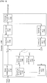
- FIG. 1 shows a schematic block diagram of an encoder for encoding a video signal, in accordance with one embodiment of the present invention.
- an encoder 100 may include an image segmentation unit 110, a transform unit 120, a quantization unit 130, an inverse quantization unit 140, an inverse transform unit 150, a filtering unit 160, a DPB (Decoded Picture Buffer) 170, an inter-prediction unit 180, an intra-prediction unit 185 and an entropy-encoding unit 190.
- an image segmentation unit 110 may include an image segmentation unit 110, a transform unit 120, a quantization unit 130, an inverse quantization unit 140, an inverse transform unit 150, a filtering unit 160, a DPB (Decoded Picture Buffer) 170, an inter-prediction unit 180, an intra-prediction unit 185 and an entropy-encoding unit 190.
- DPB Decoded Picture Buffer
- the image segmentation unit 110 may divide an input image (or, a picture, a frame) input to the encoder 100 into one or more process units.
- the process unit may be a coding tree unit (CTU), a coding unit (CU), a prediction unit (PU), or a transform unit (TU).
- CTU coding tree unit
- CU coding unit
- PU prediction unit
- TU transform unit
- the process unit may be a square block or a non-square block.
- coding unit is employed as a unit used in a process of encoding or decoding a video signal, however, the present invention is not limited thereto, another process unit may be appropriately selected based on contents of the present disclosure.
- the encoder 100 may generate a residual signal by subtracting a prediction signal output from the inter-prediction unit 180 or intra prediction unit 185 from the input image signal.
- the generated residual signal may be transmitted to the transform unit 120.
- the transform unit 120 may apply a transform technique to the residual signal to produce a transform coefficient.
- the transform process may be applied to a pixel block having the same size of a square, or to a block of a variable size other than a square.
- the quantization unit 130 may quantize the transform coefficient and transmits the quantized coefficient to the entropy-encoding unit 190.
- the entropy-encoding unit 190 may entropy-code the quantized signal and then output the entropy-coded signal as bitstreams.
- the quantized signal output from the quantization unit 130 may be used to generate a prediction signal.
- the quantized signal may be subjected to an inverse quantization and an inverse transform via the inverse quantization unit 140 and the inverse transform unit 150 in the loop respectively to reconstruct a residual signal.
- the reconstructed residual signal may be added to the prediction signal output from the inter-prediction unit 180 or intra-prediction unit 185 to generate a reconstructed signal.
- adjacent blocks may be quantized by different quantization parameters, so that deterioration of the block boundary may occur.
- This phenomenon is called blocking artifacts. This is one of important factors for evaluating image quality.
- a filtering process may be performed to reduce such deterioration. Using the filtering process, the blocking deterioration may be eliminated, and, at the same time, an error of a current picture may be reduced, thereby improving the image quality.
- the filtering unit 160 may apply filtering to the reconstructed signal and then outputs the filtered reconstructed signal to a reproducing device or the decoded picture buffer 170.
- the filtered signal transmitted to the decoded picture buffer 170 may be used as a reference picture in the inter-prediction unit 180. In this way, using the filtered picture as the reference picture in the inter-picture prediction mode, not only the picture quality but also the coding efficiency may be improved.
- the decoded picture buffer 170 may store the filtered picture for use as the reference picture in the inter-prediction unit 180.
- the inter-prediction unit 180 may perform temporal prediction and/or spatial prediction with reference to the reconstructed picture to remove temporal redundancy and/or spatial redundancy.
- the reference picture used for the prediction may be a transformed signal obtained via the quantization and inverse quantization on a block basis in the previous encoding/decoding. Thus, this may result in blocking artifacts or ringing artifacts.
- the inter-prediction unit 180 may interpolate signals between pixels on a subpixel basis using a low-pass filter.
- the subpixel may mean a virtual pixel generated by applying an interpolation filter.
- An integer pixel means an actual pixel existing in the reconstructed picture.
- the interpolation method may include linear interpolation, bi-linear interpolation and Wiener filter, etc.
- the interpolation filter may be applied to the reconstructed picture to improve the accuracy of the prediction.
- the inter-prediction unit 180 may apply the interpolation filter to integer pixels to generate interpolated pixels.
- the inter-prediction unit 180 may perform prediction using an interpolated block composed of the interpolated pixels as a prediction block.
- the intra-prediction unit 185 may predict a current block by referring to samples in the vicinity of a block to be encoded currently.
- the intra-prediction unit 185 may perform a following procedure to perform intra prediction. First, the intra-prediction unit 185 may prepare reference samples needed to generate a prediction signal. Then, the intra-prediction unit 185 may generate the prediction signal using the prepared reference samples. Thereafter, the intra-prediction unit 185 may encode a prediction mode. At this time, reference samples may be prepared through reference sample padding and/or reference sample filtering. Since the reference samples have undergone the prediction and reconstruction process, a quantization error may exist. Therefore, in order to reduce such errors, a reference sample filtering process may be performed for each prediction mode used for intra-prediction.
- the intra predictor 185 may be classified mainly into prediction mode coding and residual signal coding.
- a prediction mode of a neighboring block may be used as a prediction value for a prediction mode of the current block.
- the more accurate the prediction mode of neighboring blocks the more accurate the prediction for a prediction mode of the current block may be.
- the prediction signal generated via the inter-prediction unit 180 or the intra-prediction unit 185 may be used to generate the reconstructed signal or used to generate the residual signal.
- the inter prediction unit 180 or the intra prediction unit 185 may generate a prediction signal using all previously reconstructed signals based on a CNT coding technique to which the present invention is applied.
- FIG. 2 shows a schematic block diagram of a decoder for decoding a video signal, in accordance with one embodiment of the present invention.
- a decoder 200 may include a parsing unit(not shown), an entropy-decoding unit 210, an inverse quantization unit 220, an inverse transform unit 230, a filtering unit 240, a decoded picture buffer (DPB) 250, an inter-prediction unit 260, an intra-prediction unit 265, and a reconstruction unit(not shown).
- a reconstructed video signal output from the decoder 200 may be reproduced using a reproducing device.
- the decoder 200 may receive a video signal output from the encoder 100 of FIG. 1 , and parse syntax elements from the video signal through a parsing unit (not shown).
- the parsed signal may be entropy decoded through the entropy decoding unit 210 or may be transmitted to another function unit.
- the inverse quantization unit 220 may obtain a transform coefficient from the entropy-decoded signal using quantization step size information.
- the inverse transform unit 230 may inverse-transform the transform coefficient to obtain a residual signal.
- a reconstructed signal may be generated by adding the obtained residual signal to the prediction signal output from the inter-prediction unit 260 or the intra-prediction unit 265.
- the filtering unit 240 may apply filtering to the reconstructed signal and may output the filtered reconstructed signal to the reproducing device or the decoded picture buffer unit 250.
- the filtered signal transmitted to the decoded picture buffer unit 250 may be used as a reference picture in the inter-prediction unit 260.
- filtering unit 160 the inter-prediction unit 180 and the intra-prediction unit 185 of the encoder 100 may be equally applied to the filtering unit 240, the inter-prediction unit 260 and the intra-prediction unit 265 of the decoder 200 respectively.
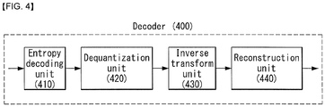
- FIGS. 3 and 4 are schematic block diagrams of an encoder and a decoder to which Conditionally Non-linear Transform (CNT) coding technique is applied according to an embodiment of the present invention.
- CNT Conditionally Non-linear Transform
- N prediction data is extracted from the N original data at once, and transform coding is then applied to the obtained N residual data or a prediction error.
- the prediction process and the transform process are sequentially performed.
- the present invention proposes a method of obtaining a transform coefficient using a previously reconstructed signal and a context signal.
- the encoder 300 of FIG. 3 includes an optimization unit 310, a quantization unit 320, and an entropy encoding unit 330.
- the decoder 400 of FIG. 4 includes an entropy decoding unit 410, a dequantization unit 420, an inverse transform unit 430, and a reconstruction unit 440.
- the optimization unit 310 obtains an optimized transform coefficient.
- the optimization unit 310 may use the following embodiments in order to obtain the optimized transform coefficient.
- a reconstruction function for reconstructing a signal may be defined as the following equation 1.
- x ⁇ R c , y
- Equation 1 x ⁇ denotes a reconstructed signal, c denotes a decoded transform coefficient, and y denotes a context signal.
- R(c,y) denotes a nonlinear reconstruction function using c and y in order to generate a reconstructed signal.
- a prediction signal may be defined as a relation between previously reconstructed values and a transform coefficient. That is, the encoder and the decoder to which the present invention is applied may generate an optimized prediction signal by taking into consideration all of previously reconstructed signals when performing a prediction process. Furthermore, a non-linear prediction function may be applied as a prediction function for generating a prediction signal.
- each of decoded transform coefficients affects the entire reconstruction process and enables control of a prediction error included in a prediction error vector.
- e indicates a prediction error signal
- c indicates a decoded transform coefficient
- T indicates a transform matrix
- the reconstructed signal may be defined as the following equation 3.
- x ⁇ 1 R 1 e 1
- y x ⁇ 2 R 2 e 2
- y , x ⁇ 1 ⁇ x ⁇ n R n e n , y , x ⁇ 1 , x ⁇ 2 ... , x ⁇ n ⁇ 1
- x ⁇ n indicates an n-th reconstructed signal
- en indicates an n-th prediction error signal
- y indicates a context signal
- Rn indicates a non-linear reconstruction function using en and y in order to generate a reconstructed signal.
- the non-linear reconstruction function Rn may be defined as the following equation 4.
- Pn indicates a non-linear prediction function including the variables in order to generate a prediction signal.
- the encoder 300 and the decoder 400 to which the present invention is applied may include the storage of candidate functions for selecting the non-linear prediction function.
- the optimization unit 310 may select an optimized non-linear prediction function in order to generate an optimized transform coefficient.
- the optimized non-linear prediction function may be selected from the candidate functions stored in the storage.
- the optimization unit 310 may generate an optimized transform coefficient by selecting the optimized non-linear prediction function as described above.
- the entropy encoding unit 330 may perform entropy encoding on the quantized transform coefficient and output a compressed bitstream.
- the decoder 400 of FIG. 4 may receive the compressed bitstream from the encoder of FIG. 3 , may perform entropy decoding through the entropy decoding unit 410, and may perform dequantization through the dequantization unit 420.
- a signal output by the dequantization unit 420 may mean an optimized transform coefficient.
- FIG. 5 is an embodiment to which the present invention may be applied and is a schematic flowchart illustrating a CNT(Conditionally Non-linear Transform) coding method.
- the CNT prediction mode indicates a mode in which prediction is performed based on a CNT coding technique, and, the CNT prediction mode may be, for example, set based on an intra prediction mode.
- the CNT prediction mode is a CNT directional mode, prediction may be performed in a corresponding prediction direction using previously decoded pixel values.
- the CNT prediction mode may be defined by the horizontal direction or the vertical direction.
- the encoder may determine an optimal block partition and accordingly be aware of whether or not NSCNT is applied (S830).
- the encoder may perform CNT coding on non-square blocks (S840).
- the present invention is not limited thereto, and the optimal block partition may be determined to be in a mixed form of a square block and a non-square block.
- non-CNT coding may be applied to the square block
- CNT coding may be applied to the non-square block.
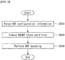
- a decoder may parse CNT configuration information from a bitstream (S910).
- the CNT configuration information represents configuration information necessary to perform CNT coding.
- the CNT configuration information may include at least one of a non-square CNT flag indicating whether non-square CNT is applied, block partition informationin which non-square CNT is applied, a CNT flag indicating whether a CNT is applied, transmission unit information for transmitting a CNT flag, or a CNT prediction mode set indicating a CNT prediction mode.
- a 16x16 block is able to be partitioned into two or four non-square blocks in a horizontal direction, a partition index indicating one of the two partition types may be needed, and the decoder may receive the partition index as additional information and use the partition index to induce a block partition.
- the decoder may perform CNT decoding on a non-square CNT block partition (S930).
- FIG. 10 is a diagram illustrating a method for performing prediction by applying the same prediction mode to non-square blocks according to an embodiment of the present invention.
- the present invention provides a method for additionally transmitting non-square block partition information.
- a different prediction mode may be applied to each non-square block.
- FIG. 11(a) shows the case where one square block is split into two non-square blocks in a vertical direction, and non-square CNT prediction may be performed on a left (first) non-square block according to a prediction mode M1, and non-square CNT prediction may be applied to a right (second) non-square block according to a prediction mode M2.
- a CNT flag indicating whether a CNT is applied to each PU may be transmitted.
- CNT prediction and intra prediction may be applied in combination to the PUs.
- FIG. 12 is a diagram illustrating a method for partitioning one square block into two or more non-square blocks according to an embodiment of the present invention.
- FIG. 12(a) shows a square block
- FIG. 12(b) shows the case where one square block is partitioned into two non-square blocks in a vertical direction
- FIG. 12(c) shows the case where one square block is partitioned into four non-square blocks in the vertical direction
- FIG. 12(d) shows the case where one square block is partitioned into two non-square blocks in a horizontal direction
- FIG. 12 € shows the case where one square block is partitioned into four non-square blocks in the horizontal direction.
- the present invention may use a fixed block partition for a specific mode.
- a specific mode for example, in the case of a vertical mode or a horizontal mode, any one of the block partitions shown in FIG. 12 may be fixed and applied.
- the block partitions shown in FIG. 12 are merely examples, and a square block may be split into a more number of non-square blocks, may be split asymmetrically, and may be split into an odd number of non-square blocks.
- a block partition having statistically good performance may be determined for each prediction mode, and such a block partition may be used in a fixed manner.
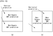
- FIG. 13 is a diagram illustrating a method for partitioning one square block into two or more non-square blocks in a prediction direction according to an embodiment of the present invention.
- the present invention may apply a different block partition according to a prediction direction or a prediction mode.
- FIG. 13(a) shows block partition being performed in the horizontal direction when prediction is performed in the vertical direction
- FIG. 13(b) shows block partition being performed in the vertical direction when prediction is performed in the horizontal direction.
- the present invention provides a method for performing CNT prediction on a non-square block by splitting a block in the horizontal direction in the case of horizontal directional prediction and in the vertical direction in the case of vertical directional prediction.
- the intra prediction modes (or CNT prediction modes) 2 to 17 are horizontal directional prediction so vertical directional block partition may be applied thereto
- the intra prediction modes (or CNT prediction modes) 19 to 34 are vertical directional prediction so a horizontal directional block partition may be applied thereto.
- the present invention may apply CNT coding to a non-square TU.
- the present invention may differently split blocks, to which non-square CNT is applied, according to a size of a target block.
- it may be set such that a 8x8 block is split into two non-square blocks, as shown in FIG. 12(b) and (d) and a 16x16 block is split into four non-square blocks, as shown in FIG. 12(c) and (e) .
- block partition information exhibiting performance optimized for each block may be transmitted additionally.
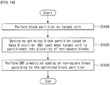
- FIG. 14 is a flowchart illustrating a method for performing CNT prediction coding on non-square blocks according to an embodiment of the present invention.
- An encoder may perform a block partition on a target unit of a video signal (S1410).
- the block partition may be performed based on a square partition or non-square partition.
- the encoder may determine an optimal block partition based on RD cost (S1420).
- the encoder may perform CNT prediction coding on a non-square block partitioned based on the optimal block partition (S1430).
- the CNT prediction coding represents performing prediction using all previously decoded pixel values.
- the same prediction mode may be applied to the plurality of non-square blocks.
- different prediction modes may be applied to at least two of the plurality of non-square blocks.
- the non-square CNT flag may be signaled through at least one of a Sequence Parameter Set (SPS), a Picture Parameter Set (PPS), a picture, a CTU, a CU, a PU, or a block.
- SPS Sequence Parameter Set
- PPS Picture Parameter Set
- a picture a CTU, a CU, a PU, or a block.
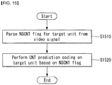
- a decoder may parse a non-CNT flag for a target unit from a video signal (S1510).
- the non-square CNT flag indicates whether CNT prediction coding is performed on a non-square block.
- the decoder may perform CNT prediction coding on the target unit based on the non-square CNT flag (S1520).
- the target unit is composed of a plurality of non-square blocks.
- the same prediction mode may be applied to the plurality of non-square blocks.
- different prediction modes may be applied to at least two of the plurality of non-square blocks.
- the decoder and the encoder to which the present invention is applied may be included in a multimedia broadcasting transmission/reception apparatus, a mobile communication terminal, a home cinema video apparatus, a digital cinema video apparatus, a surveillance camera, a video chatting apparatus, a real-time communication apparatus, such as video communication, a mobile streaming apparatus, a storage medium, a camcorder, a VoD service providing apparatus, an Internet streaming service providing apparatus, a three-dimensional (3D) video apparatus, a teleconference video apparatus, and a medical video apparatus and may be used to code video signals and data signals.
- a multimedia broadcasting transmission/reception apparatus a mobile communication terminal, a home cinema video apparatus, a digital cinema video apparatus, a surveillance camera, a video chatting apparatus, a real-time communication apparatus, such as video communication, a mobile streaming apparatus, a storage medium, a camcorder, a VoD service providing apparatus, an Internet streaming service providing apparatus, a three-dimensional (3D) video apparatus, a teleconference video apparatus, and
- the decoding/encoding method to which the present invention is applied may be produced in the form of a program that is to be executed by a computer and may be stored in a computer-readable recording medium.
- Multimedia data having a data structure according to the present invention may also be stored in computer-readable recording media.
- the computer-readable recording media include all types of storage devices in which data readable by a computer system is stored.
- the computer-readable recording media may include a BD, a USB, ROM, RAM, CD-ROM, a magnetic tape, a floppy disk, and an optical data storage device, for example.
- the computer-readable recording media includes media implemented in the form of carrier waves, e.g., transmission through the Internet.
- a bit stream generated by the encoding method may be stored in a computer-readable recording medium or may be transmitted over wired/wireless communication networks.
Landscapes
- Engineering & Computer Science (AREA)
- Multimedia (AREA)
- Signal Processing (AREA)
- Compression Or Coding Systems Of Tv Signals (AREA)
Applications Claiming Priority (2)
| Application Number | Priority Date | Filing Date | Title |
|---|---|---|---|
| US201562241760P | 2015-10-15 | 2015-10-15 | |
| PCT/KR2016/011652 WO2017065592A1 (ko) | 2015-10-15 | 2016-10-17 | 비디오 신호의 인코딩, 디코딩 방법 및 그 장치 |
Publications (2)
| Publication Number | Publication Date |
|---|---|
| EP3364658A1 true EP3364658A1 (de) | 2018-08-22 |
| EP3364658A4 EP3364658A4 (de) | 2019-07-03 |
Family
ID=58517532
Family Applications (1)
| Application Number | Title | Priority Date | Filing Date |
|---|---|---|---|
| EP16855809.6A Withdrawn EP3364658A4 (de) | 2015-10-15 | 2016-10-17 | Verfahren und vorrichtung zur codierung und decodierung eines videosignals |
Country Status (5)
| Country | Link |
|---|---|
| US (1) | US10638132B2 (de) |
| EP (1) | EP3364658A4 (de) |
| KR (1) | KR20180061235A (de) |
| CN (1) | CN108353194B (de) |
| WO (1) | WO2017065592A1 (de) |
Families Citing this family (10)
| Publication number | Priority date | Publication date | Assignee | Title |
|---|---|---|---|---|
| EP2873401B1 (de) | 2013-11-15 | 2017-03-01 | Hill-Rom S.A.S. | System und Verfahren zur automatischen Anpassung der Höhe einer Patientenliege |
| WO2017196127A1 (ko) * | 2016-05-12 | 2017-11-16 | 엘지전자 주식회사 | 임의 파티션 변환에 기초하여 비디오 신호를 처리하는 방법 |
| WO2018117892A1 (en) * | 2016-12-23 | 2018-06-28 | Huawei Technologies Co., Ltd. | An intra-prediction apparatus for extending a set of predetermined directional intra-prediction modes |
| JP2019041165A (ja) | 2017-08-23 | 2019-03-14 | 富士通株式会社 | 画像符号化装置、画像復号装置、画像処理方法、及び画像処理プログラム |
| KR102517389B1 (ko) * | 2019-02-05 | 2023-04-03 | 베이징 다지아 인터넷 인포메이션 테크놀로지 컴퍼니 리미티드 | 인트라 서브-파티션 코드 모드를 이용한 비디오 코딩 |
| CN113812159B (zh) * | 2019-05-14 | 2024-06-21 | 北京字节跳动网络技术有限公司 | 视频编解码中的缩放方法 |
| CN117499625A (zh) * | 2019-09-01 | 2024-02-02 | 北京字节跳动网络技术有限公司 | 视频编解码中预测权重的对准 |
| KR20220110301A (ko) * | 2019-12-17 | 2022-08-05 | 알리바바 그룹 홀딩 리미티드 | 화상 경계에서 블록 파티셔닝을 위한 방법들 및 장치들 |
| CN112165617B (zh) * | 2020-10-17 | 2022-09-06 | 浙江大华技术股份有限公司 | 一种视频编码方法、装置、电子设备和存储介质 |
| US12563226B2 (en) | 2021-02-24 | 2026-02-24 | Lg Electronics Inc. | Intra prediction method and device based on intra prediction mode derivation |
Family Cites Families (10)
| Publication number | Priority date | Publication date | Assignee | Title |
|---|---|---|---|---|
| US7841980B2 (en) * | 2006-05-11 | 2010-11-30 | Olympus Medical Systems Corp. | Treatment system, trocar, treatment method and calibration method |
| EP2538673A4 (de) * | 2010-01-22 | 2015-12-23 | Samsung Electronics Co Ltd | Vorrichtung und verfahren für bereichsbasierte kodierung und dekodierung |
| US20110293004A1 (en) * | 2010-05-26 | 2011-12-01 | Jicheng An | Method for processing motion partitions in tree-based motion compensation and related binarization processing circuit thereof |
| KR101824241B1 (ko) * | 2011-01-11 | 2018-03-14 | 에스케이 텔레콤주식회사 | 인트라 부가정보 부호화/복호화 장치 및 방법 |
| US8494290B2 (en) * | 2011-05-05 | 2013-07-23 | Mitsubishi Electric Research Laboratories, Inc. | Method for coding pictures using hierarchical transform units |
| US9787982B2 (en) * | 2011-09-12 | 2017-10-10 | Qualcomm Incorporated | Non-square transform units and prediction units in video coding |
| US9247254B2 (en) * | 2011-10-27 | 2016-01-26 | Qualcomm Incorporated | Non-square transforms in intra-prediction video coding |
| US9131210B2 (en) * | 2012-03-16 | 2015-09-08 | Texas Instruments Incorporated | Low-complexity two-dimensional (2D) separable transform design with transpose buffer management |
| JP2016536859A (ja) * | 2013-10-07 | 2016-11-24 | エルジー エレクトロニクス インコーポレイティド | メディア信号のエンコード及びデコード方法並びにそれを用いる装置 |
| KR101580966B1 (ko) * | 2014-01-27 | 2015-12-31 | 건국대학교 산학협력단 | Hevc 인트라 코딩을 위한 코딩 단위 크기 결정 시스템 |
-
2016
- 2016-10-17 KR KR1020187010415A patent/KR20180061235A/ko not_active Ceased
- 2016-10-17 WO PCT/KR2016/011652 patent/WO2017065592A1/ko not_active Ceased
- 2016-10-17 CN CN201680066643.3A patent/CN108353194B/zh active Active
- 2016-10-17 EP EP16855809.6A patent/EP3364658A4/de not_active Withdrawn
- 2016-10-17 US US15/767,962 patent/US10638132B2/en active Active
Also Published As
| Publication number | Publication date |
|---|---|
| KR20180061235A (ko) | 2018-06-07 |
| WO2017065592A1 (ko) | 2017-04-20 |
| US20180302620A1 (en) | 2018-10-18 |
| US10638132B2 (en) | 2020-04-28 |
| CN108353194A (zh) | 2018-07-31 |
| EP3364658A4 (de) | 2019-07-03 |
| CN108353194B (zh) | 2022-07-05 |
Similar Documents
| Publication | Publication Date | Title |
|---|---|---|
| US10630977B2 (en) | Method and apparatus for encoding/decoding a video signal | |
| US12598301B2 (en) | BDPCM-based image coding method and device therefor | |
| US10638132B2 (en) | Method for encoding and decoding video signal, and apparatus therefor | |
| US10880546B2 (en) | Method and apparatus for deriving intra prediction mode for chroma component | |
| KR20180064414A (ko) | 비디오 신호의 인코딩, 디코딩 방법 및 장치 | |
| US20230254490A1 (en) | Method and apparatus for cabac-based entropy coding | |
| US11503315B2 (en) | Method and apparatus for encoding and decoding video signal using intra prediction filtering | |
| US20230239477A1 (en) | Method and apparatus for decoding image by using transform according to block size in image coding system | |
| US20180027236A1 (en) | Method and device for encoding/decoding video signal by using adaptive scan order | |
| KR20220088501A (ko) | 적응적 루프 필터를 적용하는 비디오 또는 영상 코딩 | |
| US20180048890A1 (en) | Method and device for encoding and decoding video signal by using improved prediction filter | |
| US10382792B2 (en) | Method and apparatus for encoding and decoding video signal by means of transform-domain prediction | |
| US10893274B2 (en) | Method for processing video signal on basis of arbitrary partition transform | |
| US20200154103A1 (en) | Image processing method on basis of intra prediction mode and apparatus therefor | |
| US10523945B2 (en) | Method for encoding and decoding video signal | |
| US10785499B2 (en) | Method and apparatus for processing video signal on basis of combination of pixel recursive coding and transform coding | |
| US10432975B2 (en) | Method for encoding/decoding image and device for same | |
| EP4090031A1 (de) | Transformationsbasiertes bildcodierungsverfahren und vorrichtung dafür | |
| US10999591B2 (en) | Method and apparatus for processing video signal through target area modification | |
| KR20220088796A (ko) | 영상 정보를 시그널링하는 방법 및 장치 | |
| US20250294150A1 (en) | Method and apparatus for cabac-based entropy coding | |
| EP4648417A1 (de) | Bildcodierungs-/-decodierungsverfahren auf der basis von intraprädiktion, verfahren zur übertragung eines bitstroms und aufzeichnungsmedium mit darauf gespeichertem bitstrom |
Legal Events
| Date | Code | Title | Description |
|---|---|---|---|
| STAA | Information on the status of an ep patent application or granted ep patent |
Free format text: STATUS: THE INTERNATIONAL PUBLICATION HAS BEEN MADE |
|
| PUAI | Public reference made under article 153(3) epc to a published international application that has entered the european phase |
Free format text: ORIGINAL CODE: 0009012 |
|
| STAA | Information on the status of an ep patent application or granted ep patent |
Free format text: STATUS: REQUEST FOR EXAMINATION WAS MADE |
|
| 17P | Request for examination filed |
Effective date: 20180504 |
|
| AK | Designated contracting states |
Kind code of ref document: A1 Designated state(s): AL AT BE BG CH CY CZ DE DK EE ES FI FR GB GR HR HU IE IS IT LI LT LU LV MC MK MT NL NO PL PT RO RS SE SI SK SM TR |
|
| AX | Request for extension of the european patent |
Extension state: BA ME |
|
| DAV | Request for validation of the european patent (deleted) | ||
| DAX | Request for extension of the european patent (deleted) | ||
| A4 | Supplementary search report drawn up and despatched |
Effective date: 20190531 |
|
| RIC1 | Information provided on ipc code assigned before grant |
Ipc: H04N 19/147 20140101ALI20190524BHEP Ipc: H04N 19/157 20140101ALI20190524BHEP Ipc: H04N 19/90 20140101AFI20190524BHEP Ipc: H04N 19/61 20140101ALI20190524BHEP Ipc: H04N 19/119 20140101ALI20190524BHEP Ipc: H04N 19/176 20140101ALI20190524BHEP |
|
| STAA | Information on the status of an ep patent application or granted ep patent |
Free format text: STATUS: EXAMINATION IS IN PROGRESS |
|
| 17Q | First examination report despatched |
Effective date: 20210210 |
|
| STAA | Information on the status of an ep patent application or granted ep patent |
Free format text: STATUS: THE APPLICATION IS DEEMED TO BE WITHDRAWN |
|
| 18D | Application deemed to be withdrawn |
Effective date: 20210622 |