EP3364713B1 - Tête radio distante universelle - Google Patents
Tête radio distante universelle Download PDFInfo
- Publication number
- EP3364713B1 EP3364713B1 EP18166380.8A EP18166380A EP3364713B1 EP 3364713 B1 EP3364713 B1 EP 3364713B1 EP 18166380 A EP18166380 A EP 18166380A EP 3364713 B1 EP3364713 B1 EP 3364713B1
- Authority
- EP
- European Patent Office
- Prior art keywords
- broadband
- channelized
- uplink
- radio frequency
- broadband signal
- Prior art date
- Legal status (The legal status is an assumption and is not a legal conclusion. Google has not performed a legal analysis and makes no representation as to the accuracy of the status listed.)
- Active
Links
Images









Classifications
-
- H—ELECTRICITY
- H04—ELECTRIC COMMUNICATION TECHNIQUE
- H04W—WIRELESS COMMUNICATION NETWORKS
- H04W88/00—Devices specially adapted for wireless communication networks, e.g. terminals, base stations or access point devices
- H04W88/08—Access point devices
- H04W88/085—Access point devices with remote components
-
- H—ELECTRICITY
- H04—ELECTRIC COMMUNICATION TECHNIQUE
- H04B—TRANSMISSION
- H04B7/00—Radio transmission systems, i.e. using radiation field
- H04B7/02—Diversity systems; Multi-antenna system, i.e. transmission or reception using multiple antennas
- H04B7/04—Diversity systems; Multi-antenna system, i.e. transmission or reception using multiple antennas using two or more spaced independent antennas
- H04B7/0413—MIMO systems
-
- H—ELECTRICITY
- H04—ELECTRIC COMMUNICATION TECHNIQUE
- H04H—BROADCAST COMMUNICATION
- H04H20/00—Arrangements for broadcast or for distribution combined with broadcast
- H04H20/65—Arrangements characterised by transmission systems for broadcast
- H04H20/76—Wired systems
- H04H20/77—Wired systems using carrier waves
- H04H20/78—CATV [Community Antenna Television] systems
- H04H20/79—CATV [Community Antenna Television] systems using downlink of the CATV systems, e.g. audio broadcast via CATV network
-
- H—ELECTRICITY
- H04—ELECTRIC COMMUNICATION TECHNIQUE
- H04J—MULTIPLEX COMMUNICATION
- H04J3/00—Time-division multiplex systems
-
- H—ELECTRICITY
- H04—ELECTRIC COMMUNICATION TECHNIQUE
- H04N—PICTORIAL COMMUNICATION, e.g. TELEVISION
- H04N21/00—Selective content distribution, e.g. interactive television or video on demand [VOD]
- H04N21/20—Servers specifically adapted for the distribution of content, e.g. VOD servers; Operations thereof
- H04N21/23—Processing of content or additional data; Elementary server operations; Server middleware
- H04N21/238—Interfacing the downstream path of the transmission network, e.g. adapting the transmission rate of a video stream to network bandwidth; Processing of multiplex streams
- H04N21/2385—Channel allocation; Bandwidth allocation
-
- H—ELECTRICITY
- H04—ELECTRIC COMMUNICATION TECHNIQUE
- H04W—WIRELESS COMMUNICATION NETWORKS
- H04W72/00—Local resource management
- H04W72/04—Wireless resource allocation
- H04W72/044—Wireless resource allocation based on the type of the allocated resource
- H04W72/0453—Resources in frequency domain, e.g. a carrier in FDMA
Definitions
- Distributed base stations systems may include base station baseband signal processing functionality and base station control functionality and remote radio heads.
- Remote radio heads may include radio frequency (RF) transceivers and power amplifiers.
- RF radio frequency
- digital baseband data is transported between the baseband processing unit located in the host unit and the remotely located radio frequency (RF) transceivers located at the remote units.
- the baseband processing unit communicates with the remote radio head using channelized Common Public Radio Interface (CPRI) signals and/or Open Base Station Architecture Initiative (OBSAI) signals.
- CPRI Common Public Radio Interface
- OBSAI Open Base Station Architecture Initiative
- US 2010/278530 A1 relates to a distributed antenna system for communicating with a plurality of base stations.
- the distributed antenna system includes a system controller and a master unit communicating with at least one of the plurality of base stations.
- a remote unit communicates over a high data rate media with the master unit and/or a downstream remote unit.
- the distributed antenna system includes a controller and a digital time/space crosspoint switch controlled by the controller.
- a digitizing transceiver is in communication with the digital time/space crosspoint switch.
- the crosspoint switch is configured to transmit and receive digital data through the digitizing transceiver.
- EP0985324A2 relates to the reuse of a control channel in a distributed cellular communication system.
- At least one physical channel, the so-called physical control channel, in the radio communication system is used for transferring logical control channels.
- the physical uplink control channel can be reused with respect to logical control channels comprising an access request.
- the physical downlink control channel can be reused with respect to logical control channels comprising a message that access is granted to a mobile station or a message that someone requests contact with a mobile station.
- the physical uplink control channel and/or the physical downlink control channel is reused. This means that more connections per time unit may be established in the radio communication system.
- US 2012/057572 A1 relates to a common communication infrastructure distributes data from radio-based and Internet-based sources in a distributed antenna system (DAS) and a local area network (LAN).
- a radio equipment (RE) of the DAS interfaces to a LAN segment.
- a gateway maps radio signal data from a radio equipment controller (REC) and data packets from a switch to mixed-data frames using a radio data interface protocol for transmission in the DAS.
- the signal data and data packets are retrieved from the mixed-data frames and provided to the air interface and LAN segment, respectively.
- the radio signal data from the air interface and the data packets from the LAN segment are mapped to mixed-data frames and transmitted to the gateway.
- the gateway retrieves the signal samples and data packets from the mixed-data frames for transfer to the REC and switch, respectively.
- the embodiments described below describe a distributed base station radio system including at least one channelized broadband conversion unit communicatively coupled to at least one universal remote radio head.
- the channelized broadband conversion unit is communicatively coupled to a channelized radio frequency source, usually at a base station.
- the channelized broadband conversion unit is at least one of a Common Public Radio Interface (CPRI) base station interface, an Open Base Station Architecture Initiative (OBSAI) base station interface, and an Open Radio Interface (ORI) base station interface.
- the channelized broadband conversion source includes a representation of an individual channel at baseband.
- the channelized broadband conversion unit converts the representation of the individual channel at baseband into a broadband signal capable of representing a number of individual channels together in a single broadband signal.
- a broadband signal includes individual channels positioned within a set of spectrum that reflects each channels location within the RF spectrum. When aggregated, the individual channels within the broadband signals do not overlap each other. This broadband signal has a single center frequency while the individual channelized signals each have their own center frequency.
- This broadband signal is then distributed through a distributed base station radio switching network to at least one universal remote radio head.
- the universal remote radio head is multi-standard and capable of receiving the broadband signal and converting it to radio frequency (RF) and transmitting it using at least one antenna.
- RF radio frequency
- the universal remote radio head is not specific to a number of channels or an air protocol and does not necessarily require any hardware change when channels are added or removed, or a new modulation type or air protocol is used.
- a plurality of channelized broadband conversion units convert a plurality of channelized radio frequency signals received from a plurality of channelized radio frequency sources and representing individual channels into a single broadband signal that is transported through the distributed base station radio switching network to at least one universal remote radio head that converts the single broadband signal into radio frequency (RF) signals and transmits them using at least one antenna.
- the at least one universal remote radio head includes a single digital/analog converter and a single RF converter that can up-convert the entire broadband signal into RF spectrum having various channels.
- channelized signals are specific to a particular channel.
- the channelized signals are baseband data, such as channelized in-phase (I) and quadrature (Q) data.
- the channelized signals are not positioned relative to one another and require additional baseband conversion before RF conversion and transmission can be performed.
- systems that communicate the channelized signals to remote radio heads will require additional processing at the remote radio head to convert the channelized signals before RF conversion and transmission. Accordingly, the remote radio heads are more complex and less flexible than the universal remote radio heads described below.
- broadband signals are not specific to a particular channel and may include a number of different channels.
- the broadband signals represent either digitized or analog spectrum and are one step closer to RF signals than the channelized signals.
- the broadband signal is at an intermediate frequency that maps to a large portion of RF spectrum including a number of channels.
- the broadband signals can simply be up-converted from the intermediate frequency to radio frequency and transmitted at a universal remote radio head as described below.
- the universal remote radio heads do not need the capability of processing channelized signals before RF conversion and transmission. Accordingly, universal remote radio heads are less complex. In addition, it doesn't matter what channels are sent to the universal remote radio heads.
- the universal remote radio head communicates with subscriber units using a first set of channels at first frequencies and a second set of channels at second frequencies.
- the universal remote radio head communicates using different modulation and/or radio access technologies simultaneously.
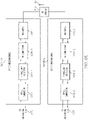
- Figure 1A-1B are block diagrams of exemplary embodiments of distributed base station radio systems 100. Each of Figures 1A-1B illustrates a different embodiment of a distributed base station radio system 100, labeled 100A-100B respectively.
- FIG. 1A is a block diagram of an exemplary embodiment of a distributed base station radio system 100, distributed base station radio system 100A.
- Distributed base station radio system 100A includes at least one channelized broadband conversion unit 102 (including channelized broadband conversion unit 102-1 and any number of optional channelized broadband conversion units 102 through optional channelized broadband conversion unit 102-A), at least one universal remote radio head 104 (including universal remote radio head 104-1 and any number of optional universal remote radio heads 104 through optional universal remote radio head 104-B), a distributed base station radio switching network 106, and optional other signal source interfaces 108 (including any number of optional other signal source interfaces 108 such as optional other signal source interface 108-1 through optional other signal source interface 108-C).
- channelized broadband conversion unit 102 including channelized broadband conversion unit 102-1 and any number of optional channelized broadband conversion units 102 through optional channelized broadband conversion unit 102-A
- at least one universal remote radio head 104 including universal remote radio head 104-1 and any number of optional universal remote radio heads 104 through optional universal remote
- Each channelized broadband conversion unit 102 is communicatively coupled to a channelized radio frequency source 110 that is configured to provide a channelized signal representing a single channel to be transported through the distributed base station radio system 100A to the channelized broadband conversion unit 102-1.
- each channelized broadband conversion unit 102 is configured to receive a channelized signal representing a single channel from a corresponding channelized radio frequency source 110.
- channelized broadband conversion unit 102-1 is communicatively coupled to channelized radio frequency source 110-1 and optional channelized broadband conversion unit 102-A is communicatively coupled to optional channelized radio frequency source 110-A.
- Each channelized broadband conversion unit 102 is also communicatively coupled to the distributed base station radio switching network 106 across a communication link 112.
- channelized broadband conversion unit 102-1 is communicatively coupled to the distributed base station radio switching network 106 across communication link 112-1 and optional channelized broadband conversion unit 102-A is communicatively coupled to the distributed base station radio switching network 106 across communication link 112-A.
- each channelized broadband conversion unit 102 is configured to convert a channelized signal from a corresponding channelized radio frequency source 110 into a downlink broadband signal and further configured to communicate the downlink broadband signal to the distributed base station radio switching network 106 (either directly or through other components of the distributed base station radio system 100A) across a respective communication link 112.
- Each downlink broadband signal contains an individual channel that is positioned within a set of spectrum that reflects its location within the RF spectrum.
- the channel in each downlink broadband signal is at a different RF frequency than the other channels to which it is being aggregated.
- the individual channels do not overlap each other and all channels can be upconverted together to radio frequency spectrum simultaneously.
- each channelized broadband conversion unit 102 is configured to receive uplink broadband signals across a respective communication link 112 from distributed base station radio switching network 106.
- Each channelized broadband conversion unit 102 is further configured to convert the received uplink broadband signal to a channelized signal for the corresponding channelized radio frequency source 110 and is further configured to communicate the channelized signal to the corresponding channelized radio frequency source 110.
- the uplink broadband signal is an aggregate of the uplink broadband signals from at least one universal remote radio head 104.
- the uplink broadband signal may be an aggregate of the uplink broadband signals from any number of universal remote radio heads 104.
- the communication links 112 are optical fibers and the communication across the communication links 112 is optical. In these embodiments, an electrical to optical conversion occurs at the channelized broadband conversion units 102.
- the communication links 112 are conductive cables (such as coaxial cable, twisted pair, etc.) and the communication across the communication links 112 is electrical.
- the communication across the communication links 112 is analog communication.
- the communication across the communication links 112 is digital communication. In exemplary embodiments, any mixture of optical, electrical, analog, and digital communication occurs across the communication links 112.
- a channelized broadband conversion unit 102 may include functionality to convert between digital and analog signals.
- Distributed base station radio switching network 106 communicatively couples the at least one channelized broadband conversion unit 102 and the optional other signal source interfaces 108 with the at least one universal remote radio head 104.
- Distributed base station radio switching network 106 may include one or more distributed base station radio switches or other components that functionally distributes downlink broadband signals from the at least one channelized broadband conversion unit 102 to the at least one universal remote radio head 104.
- the distributed base station radio switching network 106 aggregates downlink broadband signals from a plurality of channelized broadband conversion units 102 into a single aggregate downlink broadband signal that is routed to at least one universal remote radio head 104.
- Distributed base station radio switching network 106 also functionally distributes uplink broadband signals from the at least one universal remote radio head 104 to the at least one channelized broadband conversion unit 102.
- the distributed base station radio switching network 106 aggregates uplink broadband signals from a plurality of universal remote radio heads 104 into a single aggregate uplink broadband signal that is routed to at least one channelized broadband conversion unit 102.
- the communication links 122 between the other signal source interfaces 108 and the distributed base station radio switching network 106 are optical fibers and the communication across the communication links 122 are optical. In these embodiments, an electrical to optical conversion occurs at the other signal source interfaces 108.
- the communication links 122 are conductive cables (such as coaxial cable, twisted pair, etc.) and the communication across the communication links 122 is electrical.
- the communication across the communication links 122 is analog communication.
- the communication across the communication links 122 is digital communication. In exemplary embodiments, any mixture of optical, electrical, analog, and digital communication occurs across the communication links 122.
- an other signal source interface 108 may include functionality to convert between digital and analog signals.
- Each universal remote radio head 104 is communicatively coupled to the distributed base station radio switching network 106 across a communication link 114.
- universal remote radio head 104-1 is communicatively coupled to the distributed base station radio switching network 106 across communication link 114-1
- optional universal remote radio head 104-B is communicatively coupled to the distributed base station radio switching network 106 across communication link 114-B.
- Each universal remote radio head 104 includes components configured for converting between at least one downlink broadband signal and at least one radio frequency band signal and at least one radio frequency antenna 116 configured to transmit and receive signals in the at least one radio frequency band to/from at least one subscriber unit 118.
- the downlink broadband signal is an aggregate of multiple downlink broadband signals each with a channel positioned within a set of spectrum that reflects its location within the RF spectrum.
- the individual channels can be converted to the at least one radio frequency band signals simultaneously.
- each universal remote radio head 104 is configured to convert the at least one downlink broadband signal into a downlink radio frequency (RF) signal in a radio frequency band. In exemplary embodiments, this may include digital to analog converters and oscillators. Each universal remote radio head 104 is further configured to transmit the downlink radio frequency signal in the radio frequency band to at least one subscriber unit 118 using at least one radio frequency antenna 116. In a specific exemplary embodiment, universal remote radio head 104-1 is configured to convert the at least one downlink broadband signal received from the distributed base station radio switching network 106 into a downlink radio frequency signal in a radio frequency band.
- RF radio frequency
- Universal remote radio head 104-1 is further configured to transmit the downlink radio frequency signal in a radio frequency band using a radio frequency band antenna 116-1 to at least one subscriber unit 118-1.
- universal remote radio head 104-1 is configured to convert the at least one downlink broadband signal received from the distributed base station radio switching network 106 into a plurality of downlink radio frequency signals in a plurality of radio frequency bands.
- universal remote radio head 104-1 is further configured to transmit the plurality of downlink radio frequency signals in the plurality of radio frequency bands using the radio frequency band antenna 116-1 and optional other radio frequency band antennas 116 through optional other radio frequency band antenna 116-D.
- the universal remote radio head 104-1 is configured to transmit one downlink radio frequency signal to one subscriber unit 118-1 using an antenna 116-1 and another radio frequency signal to one subscriber unit 118-E using another antenna 116-D.
- other combinations of radio frequency antennas 116 and other components are used to communicate other combinations of radio frequency signals in other various radio frequency bands to various subscriber units 118, such as but not limited to using multiple antenna to communicate with a single subscriber unit 118.
- each universal remote radio head 104 is configured to receive uplink radio frequency signals from at least one subscriber unit 118 using at least one radio frequency antenna 116. Each universal remote radio head 104 is further configured to convert the radio frequency signals to at least one uplink broadband signal. Each universal remote radio head 104 is further configured to aggregate the at least one uplink broadband signal into an aggregate uplink broadband signal and further configured to communicate the aggregate uplink broadband signal across at least one communication link 114 to the distributed base station radio switching network. In exemplary embodiments, universal remote radio heads 104 multiplex uplink signals in different bands onto the same interface for communication to the next upstream element.
- each uplink broadband signal contains a channel that is positioned within a set of spectrum that reflects its location within the RF spectrum.
- the individual channels themselves from the aggregated uplink broadband signals do not overlap each other when multiple uplink broadband signals are aggregated together.
- the communication links 114 are optical fibers and the communication across the communication links 114 is optical. In these embodiments, an electrical to optical conversion occurs at the universal remote radio heads 104.
- the communication links 114 are conductive cables (such as coaxial cable, twisted pair, etc.) and the communication across the communication links 114 is electrical.
- the communication across the communication links 114 is analog communication.
- the communication across the communication links 114 is digital communication. In exemplary embodiments, any mixture of optical, electrical, analog, and digital communication occurs across the communication links 114.
- a universal remote radio head 104 may include functionality to convert between digital and analog signals.
- FIG. 1B is a block diagram of an exemplary embodiment of a distributed base station radio system 100, distributed base station radio system 100B.
- Distributed base station radio system 100B includes at least one channelized broadband conversion unit 102 (including channelized broadband conversion unit 102-1 and any number of optional channelized broadband conversion units 102 through optional channelized broadband conversion unit 102-A), at least one universal remote radio head 104 (including universal remote radio head 104-1 and any number of optional universal remote radio heads 104 through optional universal remote radio head 104-B), a distributed base station radio switch 124, and optional other signal source interfaces 108 (including any number of optional other signal source interfaces 108 such as optional other signal source interface 108-1 through optional other signal source interface 108-C).
- channelized broadband conversion unit 102 including channelized broadband conversion unit 102-1 and any number of optional channelized broadband conversion units 102 through optional channelized broadband conversion unit 102-A
- at least one universal remote radio head 104 including universal remote radio head 104-1 and any number of optional universal remote radio heads 104 through optional universal remote radio
- Distributed base station radio system 100B includes similar components to distributed base station radio system 100A described above and operates according to similar principles and methods as distributed base station radio system 100A described above. The difference between distributed base station radio system 100B and distributed base station radio system 100A is that the distributed base station radio switching network 106 is replaced with a single distributed base station radio switch 124.
- Distributed base station radio switch 124 communicatively couples the at least one channelized broadband conversion unit 102 and the optional other signal source interfaces 108 with the at least one universal remote radio head 104.
- Distributed base station radio switch 124 functionally distributes downlink broadband signals from the at least one channelized broadband conversion unit 102 to the at least one universal remote radio head 104.
- the distributed base station radio switch 124 aggregates downlink broadband signals from a plurality of channelized broadband conversion units 102 into a single aggregate downlink broadband signal that is routed to at least one universal remote radio head 104.
- Distributed base station radio switch 124 also functionally distributes uplink broadband signals from the at least one universal remote radio head 104 to the at least one channelized broadband conversion unit 102 and any optional channelized broadband conversion units 102 and/or optional other signal source interfaces 108.
- the distributed base station radio switch 124 aggregates uplink broadband signals from a plurality of universal remote radio heads 104 into a single aggregate uplink broadband signal that is routed to at least one channelized broadband conversion unit 102.
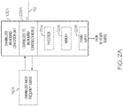
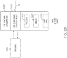
- Figures 2A-2C are block diagrams of exemplary embodiments of channelized broadband conversion units 102 used in distributed base station radio systems, such as the exemplary distributed base station radio system 100 described above. Each of Figures 2A-2C illustrates a different embodiment of a type of base station network interface 102, labeled 102A-102C respectively.
- FIG. 2A is a block diagram of an exemplary embodiment of a channelized broadband conversion unit 102, channelized broadband conversion unit 102A.
- Channelized broadband conversion unit 102A includes channelized to broadband conversion module 202A, an optional processor 204, optional memory 206, and an optional power supply 208.
- channelized to broadband conversion module 202A is communicatively coupled to at least one channelized radio frequency source 110.
- Channelized to broadband conversion module 202A is also communicatively coupled to at least one communication link 112.
- the communication link 112 is an optical communication link across a fiber optic cable, though it can also be other types of wired or wireless links in other embodiments.
- the channelized to broadband conversion module 202 is implemented using optional processor 204 and optional memory 206.
- the optional power supply 208 provides power to the various elements of the channelized broadband conversion unit 102A.
- channelized to broadband conversion module 202A is configured to receive a channelized downlink signal from the channelized radio frequency source 110A.
- the channelized to broadband conversion module 202A is further configured to convert the channelized downlink signal to a downlink broadband signal.
- the channelized to broadband conversion module 202 (or another additional component) further converts the downlink broadband signal from electrical signals to optical signals for output on an optical communication link 112.
- the downlink broadband signal is transported using a conductive communication medium, such as coaxial cable or twisted pair, and the optical conversion is not necessary.
- the channelized to broadband conversion module 202 (or another additional component) further converts between digital and analog signals as required.
- channelized to broadband conversion module 202A is configured to receive an uplink broadband signal from communication link 112.
- the channelized to broadband conversion module 202A (or another additional component) is configured to convert the uplink broadband signal between received optical signals and electrical signals.
- the uplink broadband signal is transported using a conductive communication medium, such as coaxial cable or twisted pair, and the optical conversion is not necessary.
- the channelized to broadband conversion module 202 (or another additional component) further converts between digital and analog signals as required.
- the channelized to broadband conversion module 202A is further configured to convert the uplink broadband signal to at least one uplink channelized signal.
- Channelized to broadband conversion module 202A is further configured to communicate the uplink channelized signals to the channelized radio frequency source 110A.
- FIG. 2B is a block diagram of an exemplary embodiment of a channelized broadband conversion unit 102, Common Public Radio Interface (CPRI) broadband conversion unit 102B.
- CPRI broadband conversion unit 102B includes Common Public Radio Interface (CPRI) to broadband conversion module 202B, an optional processor 204, optional memory 206, and an optional power supply 208.
- CPRI broadband conversion unit 102B includes similar components to channelized broadband conversion unit 102A and operates according to similar principles and methods as channelized broadband conversion unit 102A.
- the difference between CPRI broadband conversion unit 102B and the channelized broadband conversion unit 102A is that the CPRI broadband conversion unit 102B is CPRI specific and includes the CPRI to broadband conversion module 202B that is communicatively coupled to at least one Common Public Radio Interface (CPRI) source 110B.
- CPRI Common Public Radio Interface
- CPRI broadband conversion unit 102B converts between CPRI channelized signals and broadband signals.
- CPRI broadband conversion unit 102B converts downlink CPRI channelized signals into a downlink broadband signal.
- CPRI broadband conversion unit 102B converts an uplink broadband signal into uplink CPRI channelized signals.
- FIG. 2C is a block diagram of an exemplary embodiment of a channelized broadband conversion unit 102, Open Base Station Architecture Initiative (OBSAI) broadband conversion unit 102C.
- OBSAI broadband conversion unit 102C includes Open Base Station Architecture Initiative (OBSAI) to broadband conversion module 202C, an optional processor 204, optional memory 206, and an optional power supply 208.
- OBSAI broadband conversion unit 102C includes similar components to channelized broadband conversion unit 102A and operates according to similar principles and methods as channelized broadband conversion unit 102A.
- OBSAI broadband conversion unit 102C is OBSAI specific and includes the OBSAI to broadband conversion module 202C that is communicatively coupled to at least one Open Base Station Architecture Initiative (OBSAI) source 110C.
- OBSAI broadband conversion unit 102C converts between OBSAI channelized signals and broadband signals.
- OBSAI broadband conversion unit 102C converts downlink OBSAI channelized signals into a downlink broadband signal.
- OBSAI broadband conversion unit 102C converts an uplink broadband signal into uplink OBSAI channelized signals.
- FIG. 3 is a block diagram of an exemplary embodiment of other signal source interface 108 used in distributed base station radio systems, such as the exemplary distributed base station radio system 100.
- Other signal source interface 108 includes a signal source to broadband signal conversion module 302, an optional processor 304, optional memory 306, and an optional power supply 308.
- signal source to broadband conversion module 302 is communicatively coupled to at least one other signal source 120.
- Signal source to broadband conversion module 302 is also communicatively coupled to at least one communication link 122.
- the communication link 122 is an optical communication link across a fiber optic cable, though it can also be other types of wired or wireless links in other embodiments.
- the signal source to broadband conversion module 302 is implemented using optional processor 304 and optional memory 306.
- the optional power supply 308 provides power to the various elements of the other signal source interface 302.
- signal source to broadband conversion module 302 is configured to receive a downlink signal from the other signal source 120.
- the signal source to broadband signal conversion module 302 is further configured to convert the downlink signal to a downlink broadband signal.
- the signal source to broadband signal conversion module 302 (or another additional component) is further configured to convert the downlink broadband signal from electrical signals to optical signals for output on an optical communication link 122.
- the downlink broadband signal is transported using a conductive communication medium, such as coaxial cable or twisted pair, and the optical conversion is not necessary.
- the signal source to broadband signal conversion module 302 (or another additional component) further converts between digital and analog signals as required.
- signal source to broadband signal conversion module 302 is configured to receive an uplink broadband signal from communication link 122.
- the signal source to broadband signal conversion module 302 (or another additional component) is configured to convert the uplink broadband signal between received optical signals and electrical signals.
- the uplink broadband signal is transported using a conductive communication medium, such as coaxial cable or twisted pair, and the optical conversion is not necessary.
- the signal source to broadband signal conversion module 302 (or another additional component) further converts between digital and analog signals as required.
- the signal source to broadband signal conversion module 302 is further configured to convert the uplink broadband signal to at least one uplink signal.
- Signal source to broadband signal conversion module 302 is further configured to communicate the uplink signals to the other signal source 120.
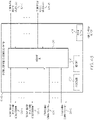
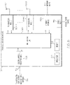
- Figures 4A-4C are block diagrams of exemplary embodiments of distributed base station radio switch 124 used in distributed base station radio systems, such as the exemplary distributed base station radio system 100 described above. Each of Figures 4A-4C illustrates a different embodiment of distributed base station radio system 100, labeled distributed base station radio switch 124A-124C respectively.
- Each electro-optical conversion module 404 is communicatively coupled to a channelized broadband conversion unit 102 across a communication link 112. In the forward path, each electro-optical conversion module 404 is configured to receive a downlink broadband signal from at least one channelized broadband conversion unit 102 across a communication link 112. Specifically, electro-optical conversion module 404-1 is configured to receive a downlink broadband signal from the channelized broadband conversion unit 102-1 across communication link 112-1 and optional electro-optical conversion module 404-A is configured to receive a downlink broadband signal from the optional channelized broadband conversion unit 102-A across optional communication link 112-A. Each electro-optical conversion module 404 is configured to convert the downlink broadband signal from optical to electrical signals, which are then passed onto the routing unit 402.
- each electro-optical conversion module 404 is configured to receive an uplink broadband signal in an electrical format from the routing unit 402 and to convert the uplink broadband signal to an optical format for communication across a communication link 112 to a channelized broadband conversion unit 102.
- the electro-optical conversion module 404 (or another additional component) further converts between digital and analog signals as required.
- Each optional electro-optical conversion module 408 is communicatively coupled to an optional other signal source interface 108 across a communication link 122. In the forward path, each electro-optical conversion module 408 is configured to receive a downlink broadband signal from at least one other signal source interface 108 across a communication link 122. Specifically, optional electro-optical conversion module 408-1 is configured to receive a downlink broadband signal from the optional other signal source interface 108-1 across optional communication link 122-1 and optional electro-optical conversion module 408-C is configured to receive a downlink broadband signal from the optional other signal source interface 108-C across optional communication link 122-C. Each electro-optical conversion module 408 is configured to convert the downlink broadband signal from optical to electrical signals, which are then passed onto the routing unit 402.
- each electro-optical conversion module 408 is configured to receive an uplink broadband signal in an electrical format from the routing unit 402 and to convert the uplink broadband signal to an optical format for communication across a communication link 112 to an other signal source interface 108.
- the electro-optical conversion module 408 (or another additional component) further converts between digital and analog signals as required.
- this routing includes aggregation of a plurality of downlink broadband signals from a plurality of electro-optical conversion modules 404 and/or electro-optical conversion modules 408 into a single downlink broadband signal that is passed to at least one electro-optical conversion module 406.
- the same or different downlink aggregate broadband signals are routed to a plurality of electro-optical conversion modules 406.
- the first and second subsets are identical.
- downlink broadband signals from greater number of subsets of channelized broadband conversion units 102 and other signal source interfaces 108 are aggregated and transferred to the universal remote radio head 104.
- this routing includes separation of a single aggregate downlink broadband signal from a single electro-optical conversion module 404 into a plurality of downlink broadband signals that are passed to a plurality of electro-optical conversion modules 406.
- the same or different downlink broadband signals are routed to a plurality of electro-optical conversion modules 406.
- the routing unit 402 is configured to separate and route downlink broadband signals destined for a first subset of universal remote radio heads 104 from a first downlink aggregate broadband signal received from a single channelized broadband conversion unit 102 (such as channelized broadband conversion unit 102-1) and is further configured to separate and route downlink broadband signals destined for a second subset of universal remote radio heads 104 from a second downlink aggregate broadband signal received from a second channelized broadband conversion unit 102 (such as channelized broadband conversion unit 102-A).
- the first and second subsets partially overlap.
- the first and second subsets are identical.
- downlink broadband signals are destined to greater number of subsets of universal remote radio heads 104.
- the routing unit 402 receives at least one uplink broadband signal from at least one electro-optical conversion module 406 (such as electro-optical conversion module 406-1) from a universal remote radio head 104 and routes the at least one uplink broadband signal to at least one electro-optical conversion module 404 (such as electro-optical conversion module 404-1) for eventual communication to a channelized broadband conversion unit 102.
- this routing includes aggregation of a plurality of uplink broadband signals from a plurality of electro-optical conversion modules 406 into a single uplink broadband signal that is passed to at least one electro-optical conversion module 404.
- the same or different uplink aggregate broadband signals are routed to a plurality of electro-optical conversion modules 404 and/or optional electro-optical conversion modules 408.
- the routing unit 402 is configured to aggregate and route uplink broadband signals from a first subset of universal remote radio heads 104 into a first uplink aggregate broadband signal that is transferred to at least a first channelized broadband conversion unit 102-1 via electro-optical conversion module 404-1 and communication link 112-1 and is further configured to aggregate and route uplink broadband signals from a second subset of universal remote radio heads 104 into a second uplink aggregate broadband signal that is transferred to at least a second channelized broadband conversion unit 102-A via second electro-optical conversion module 404-A and communication link 112-A.
- the first and second subsets partially overlap. In other exemplary embodiments, the first and second subsets are identical. In other exemplary embodiments, uplink broadband signals are aggregated and/or routed from a greater number of subsets of universal remote radio heads 104.
- this routing includes separation of a single aggregate uplink broadband signal from a single universal remote radio head 104 into a plurality of uplink broadband signals that are passed to a plurality of electro-optical conversion modules 404 and/or electro-optical conversion modules 208-1.
- the same or different uplink broadband signals are routed to a plurality of electro-optical conversion modules 404.
- the routing unit 402 is configured to separate and route uplink broadband signals destined for a first set of channelized broadband conversion units 102 from a first aggregate uplink broadband signal received from a single universal remote radio head 104 (such as universal remote radio head 104-1) and is further configured to separate and route uplink broadband signals destined for a second subset of channelized broadband conversion units 102 from a second aggregate uplink broadband signal received from a second universal remote radio head 104 (such as universal remote radio head 104-B).
- the first and second subsets partially overlap.
- the first and second subsets are identical.
- uplink broadband signals are destined to greater number of subsets of channelized broadband conversion units 102 and/or other signal source interfaces 108.
- this routing includes aggregation of a plurality of uplink broadband signals from a plurality of universal remote radio heads 104 via a plurality of electro-optical conversion modules 406 into a single aggregate uplink broadband signal that is passed to at least one channelized broadband conversion unit 102 through at least one electro-optical conversion module 404.
- the same or different uplink aggregate broadband signals are routed to a plurality of electro-optical conversion modules 406.
- the electrical and optical signals communicated between the channelized broadband conversion units 102, other signal source interfaces 108, universal remote radio heads 104, the distributed base station radio switch 124A, and within the distributed base station radio switch 124A can be any combination of digital and analog signals. In exemplary embodiments, these electrical signals are digital signals. In other exemplary embodiments, these electrical signals are analog signals. In other exemplary embodiments, these electrical signals include a combination of digital and analog signals. In exemplary implementations, the communication between one or more channelized broadband conversion units 102 and the distributed base station radio switch 124A is digital and the communication between the distributed base station radio switch 124A and one or more universal remote radio heads 104 is analog.
- the communication between one or more channelized broadband conversion units 102 and the distributed base station radio switch 124A is analog and the communication between the distributed base station radio switch 124A and one or more universal remote radio heads 104 is digital.
- the communication between a first subset of the channelized broadband conversion units 102 and/or other signal source interfaces 108 and the distributed base station radio switch 124A is digital and the communication between a second subset of the channelized broadband conversion units 102 and/or other signal source interfaces 108 and the distributed base station radio switch 124A is analog.
- the communication between the distributed base station radio switch 124A and a first set of universal remote radio heads 104 is digital while the communication between the distributed base station radio switch 124A and a second set of universal remote radio heads 104 is analog.
- the routing unit 402 includes functionality to convert between digital and analog signals as appropriate.
- FIG. 4B is a block diagram of an exemplary distributed base station radio switch 124B including a routing unit 402.
- the routing unit 402 is implemented using optional processor 410 and memory 412.
- Exemplary distributed base station radio switch 124B includes similar components to distributed base station radio switch 124A and operates according to similar principles and methods as distributed base station radio switch 124A described above.
- the difference between distributed base station radio switch 124B and distributed base station radio switch 124A is that distributed base station radio switch 124B does not include any electro-optical conversion modules because the signals between the channelized broadband conversion units 102, the other signal source interfaces 108, and the universal remote radio heads 104 are communicated as electrical signals and not optical signals and do not need to be converted to and from optical signals.
- these electrical and optical signals can be any combination of digital and analog signals.
- Figure 4C is a block diagram of an exemplary distributed base station radio switch 124C including a routing unit 402 and at least one electro-optical conversion module 406 (including electro-optical conversion module 406-1 and any amount of optional electro-optical conversion modules 406 through electro-optical conversion module 406-B).
- the routing unit 402 and/or some portion of the functionality of at least one electro-optical conversion module 406 is implemented using optional processor 410 and memory 412.
- Exemplary distributed base station radio switch 124C includes similar components to distributed base station radio switch 124A and operates according to similar principles and methods as distributed base station radio switch 124A described above.
- distributed base station radio switch 124C does not include electro-optical conversion modules 404 between the channelized broadband conversion units 102 and the routing unit 402 or the other signal source interfaces 108 and the routing unit 402 because the signals between routing unit 402, the channelized broadband conversion units 102, and the other signal source interfaces 108 are communicated as electrical signals and are not optical signals and do not need to be converted to and from optical signals.
- these electrical and optical signals can be any combination of digital and analog signals.
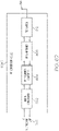
- FIG. 5 is a block diagram of an exemplary embodiment of a universal remote radio head 104 used in a distributed base station radio system 100.
- the universal remote radio head 104 includes a multiplexing unit 502, at least one radio frequency (RF) conversion module 504-1 (including RF conversion module 504-1 and any amount of optional RF conversion modules 504 through optional conversion module 504-C), optional electro-optical conversion module 506, optional Ethernet interface 508, optional processor 510, optional memory 512, and optional power supply 514.
- multiplexing unit 502, at least one RF conversion module 504, optional electro-optical conversion module 506, and/or optional Ethernet interface 508 are implemented at least in part by optional processor 510 and memory 512 of universal remote radio head 104.
- the optional power supply 514 powers the various components of universal remote radio head 105.
- the optional electro-optical conversion module 506 is communicatively coupled to the universal remote radio head switching network 106 across a communication link 114.
- the optional electro-optical conversion module 506 is configured to receive a downlink broadband signal from the distributed base station radio switching network 106 and/or the distributed base station radio switch 124 across a communication link 114.
- the optional electro-optical conversion module 506 is configured to convert the downlink broadband signal from optical to electrical format, which is then passed onto the multiplexing unit 502.
- the optional electro-optical conversion module 506 is configured to receive an uplink broadband signal from the multiplexing unit 502.
- the optional electro-optical conversion module 506 is further configured to convert the uplink broadband signal from electrical to optical format, which is then passed onto the distributed base station radio switching network 106 and/or the distributed base station radio switch 124 across the communication link 114.
- more than one electro-optical conversion module 506 is coupled across more than one communication link 114 to the same distributed base station radio switch 124, an intermediary device, and/or another distributed base station radio switch 124.
- the signals communicated between the universal remote radio head 104 and the distributed base station radio switching network 106 and/or the distributed base station radio switch 124 are electrical signals and do not require any conversion between optical and electrical.
- the electro-optical conversion module 506 (or another additional component) further converts between digital and analog signals as required.
- the multiplexing unit 502 is communicatively coupled between the electro-optical conversion module 506 and/or the distributed base station radio switching network 106 and the at least one RF conversion module 504 and the optional Ethernet interface 508.
- the multiplexing unit 502 is configured to receive a downlink broadband signal from the distributed base station radio switching network 106 and/or a distributed base station radio switch 124 directly or via the optional electro-optical conversion module 506.
- the multiplexing unit 502 simulcasts the broadband signal to each RF conversion module 504.
- the multiplexing unit 502 splits apart individual downlink broadband signals from a downlink aggregate broadband signal and passes them to a plurality of RF conversion modules 504.
- one of the downlink broadband signals communicated to one of the RF conversion modules 504 pertains to a first mobile access band and/or technology while another downlink broadband signal communicated to another one of the RF conversion modules 504 pertains to a second mobile access band and/or technology.
- the multiplexing unit 502 splits off a signal and communicates it to the Ethernet interface 508.
- other types of data are carried in the downlink broadband signals.
- the multiplexing unit 502 is configured to receive upstream signals from various radio frequency (RF) conversion modules 504 and is further configured to multiplex a plurality of upstream signals into a single uplink broadband signal.
- the multiplexing unit 502 is configured to aggregate a plurality of upstream signals from various radio frequency (RF) conversion modules 504 into a single uplink broadband signal.
- the multiplexing unit 502 is further configured to communicate the uplink broadband signal to distributed base station radio switching network 106 and/or the distributed base station radio switch 124 directly or via the optional electro-optical conversion module 506.
- Each RF conversion module 504 is communicatively coupled to the multiplexing unit 502 and is coupled to and/or includes at least one antenna 116. Each RF conversion module 504 is configured to convert between at least one downlink broadband signal and radio frequency signals in at least one radio frequency band. Each RF conversion module is configured to communicate radio frequency signals in the at least one radio frequency band across an air medium with at least one subscriber using at least one antenna 116.
- each RF conversion module 504 is configured to convert at least one downlink signal into a downlink radio frequency (RF) signal in a radio frequency band. In exemplary embodiments, this may include digital to analog converters and oscillators. Each RF conversion module 504 is further configured to transmit the downlink radio frequency signals in the radio frequency band to at least one subscriber unit 118 using at least one antenna 116. In a specific embodiment, radio frequency conversion module 504-1 is configured to convert at least one downlink broadband signal into a downlink radio frequency signal in a radio frequency band. Each RF conversion module 504 is further configured to transmit the downlink radio frequency signal in a radio frequency band using a radio frequency antenna 116-1 to at least one wireless subscriber unit.
- RF radio frequency
- radio frequency conversion module 504-1 is configured to convert a first downlink signal into a first downlink radio frequency signal in a first radio frequency band and to transmit the first downlink radio frequency signal in the first radio frequency band to at least one wireless subscriber using the antenna 116-1.
- radio frequency conversion module 504-2 is configured to convert a second downlink broadband signal into a second downlink radio frequency signal in a second radio frequency band and to transmit the second downlink radio frequency signal in the second radio frequency band to at least one wireless subscriber unit 118 using the antenna 116-2.
- one radio frequency conversion module 504-1 and antenna 116-1 pair transports to a first set of wireless subscriber units 118 in a first band and another radio frequency conversion module 504-C and antenna 116-C pair transports to a second set of wireless subscriber units 118 in a second band.
- Other combinations of radio frequency conversion module 504 and antenna 116 pairs are used to communicate other combinations of radio frequency signals in other various radio frequency bands to various subscriber units 118, such as but not limited to MIMO or carrier aggregation where signals from multiple antennas go to a single subscriber unit 118.
- each RF conversion module 504 is configured to receive uplink radio frequency signals from at least one subscriber unit 118 using at least one radio frequency antenna 116. Each radio frequency conversion module 504 is further configured to convert the radio frequency signals to at least one uplink broadband signal. Each radio frequency conversion module 504 is further configured to communicate the uplink broadband signal to the broadband signal multiplexing unit 502.
- FIGS 6A-6E are block diagrams of exemplary embodiments of radio frequency (RF) conversion modules of remote antenna units 106 used in distributed antenna systems, such as exemplary distributed antenna system 100 described above.
- RF radio frequency
- Figure 6A is a block diagram of an exemplary RF conversion module 504A including an optional signal stream conditioner 602, an RF frequency converter 604, an optional RF conditioner 606, and an RF duplexer 608 coupled to a single antenna 116.
- the optional signal conditioner 602 is communicatively coupled to a multiplexing unit 502 and the radio frequency (RF) converter 604.
- the optional signal conditioner 602 conditions the downlink broadband signal (for example, through amplification, attenuation, and filtering) received from the remote multiplexing unit 502 and passes the downlink signal to the RF converter 604.
- the optional signal conditioner 602 conditions the uplink broadband signal (for example, through amplification, attenuation, and filtering) received from the RF converter 604 and passes the uplink broadband signal to the remote multiplexing unit 502.
- the RF converter 604 is communicatively coupled to either the multiplexing unit 502 or the optional signal conditioner 602 on one side and to either RF duplexer 608 or the optional RF conditioner 606 on the other side.
- the RF converter 604 converts a downlink broadband signal to downlink radio frequency (RF) signals and passes the downlink RF signals onto either the RF duplexer 608 or the optional RF conditioner 606.
- the RF converter 604 converts uplink radio frequency (RF) signals received from either the RF duplexer 608 or the optional RF conditioner 606 to an uplink broadband signal and passes the uplink broadband signal to either the multiplexing unit 502 or the optional signal conditioner 602.
- the optional RF conditioner 606 is communicatively coupled between the RF converter 604 and the RF duplexer 608.
- the RF conditioner 606 performs gain adjustment and filtering on the downstream and upstream RF signals.
- the RF duplexer 608 is communicatively coupled to either the RF frequency converter 604 or the optional RF conditioner 606 on one side and the antenna 116 on the other side.
- the RF duplexer 608 duplexes the downlink RF signals with the uplink RF signals for transmission/reception using the antenna 116.
- FIG. 6B is a block diagram of an exemplary RF conversion module 504B including an optional signal conditioner 602, an RF frequency converter 604, an optional RF conditioner 606 coupled to a downlink antenna 116A and an uplink antenna 116B.
- RF conversion module 504B includes similar components to RF conversion module 504A and operates according to similar principles and methods as RF conversion module 504A described above. The difference between RF conversion module 504B and RF conversion module 504A is that RF conversion module 504B does not include RF duplexer 608 and instead includes separate downlink antenna 116A used to transmit RF signals to at least one subscriber unit 118 and uplink antenna 116B used to receive RF signals from at least one subscriber unit 118.
- FIG. 6C is a block diagram of an exemplary RF conversion module 504C-1 and exemplary RF conversion module 504C-2 that share a single antenna 116 through an RF diplexer 610.
- the RF conversion module 504C-1 includes an optional signal conditioner 602-1 an RF frequency converter 604-1, an optional RF conditioner 606-1, and an RF duplexer 608-1 communicatively coupled to RF diplexer 610 that is communicatively coupled to antenna 116.
- the RF conversion module 504C-2 includes an optional signal conditioner 602-2, an RF frequency converter 604-2, an optional RF conditioner 606-2, and an RF duplexer 608-2 communicatively coupled to RF diplexer 610 that is communicatively coupled to antenna 116.
- Each of RF conversion module 504C-1 and 504C-2 operate according to similar principles and methods as RF conversion module 504A described above.
- the difference between RF conversion modules 504C-1 and 504C-2 and RF conversion module 504A is that RF conversion modules 504C-1 and 504C-2 are both coupled to a single antenna 116 through RF diplexer 610.
- the RF diplexer 610 diplexes the duplexed downlink and uplink signals for both RF conversion module 504C-1 and 504C-2 for transmission/reception using the single antenna 116.
- FIG. 6D is a block diagram of an exemplary RF conversion module 504D including an optional signal conditioner 602, an RF frequency converter 604, an optional RF conditioner 606, and a time division duplexing (TDD) switch 612 coupled to an antenna 116.
- RF conversion module 504D includes similar components to RF conversion module 504A and operates according to similar principles and methods as RF conversion module 504A described above. The difference between RF conversion module 504D and RF conversion module 504A is that RF conversion module 504D does not include RF duplexer 608 and instead includes the TDD switch 612 that allows the RF conversion module 504D to switch between transmit and receive modes at different times based on a TDD signal that can be supplied from other components in the system.
- TDD time division duplexing
- FIG. 6E is a block diagram of an exemplary RF conversion module 504E-1 and exemplary RF conversion module 504E-2 that share a single antenna 116 through an RF diplexer 610.
- the RF conversion module 504E-1 includes an optional signal conditioner 602-1, an RF frequency converter 604-1, an optional RF conditioner 606-1, and a TDD switch 612-1 communicatively coupled to RF diplexer 610 that is communicatively coupled to antenna 116.
- the RF conversion module 504E-2 includes an optional signal conditioner 602-2, an RF frequency converter 604-2, an optional RF conditioner 606-2, and a TDD switch 612-2 communicatively coupled to RF diplexer 610 that is communicatively coupled to antenna 116.
- Each of RF conversion module 504E-1 and 504E-2 operate according to similar principles and methods as RF conversion modules 504C-1 and 504C-2 described above.
- the difference between RF conversion modules 504E-1 and 504E-2 and RF conversion modules 504C-1 and 504C-2 is that RF conversion modules 504E-1 and 504E-2 do not include RF duplexers 608-1 and 608-2 and instead include TDD switches 612-1 and 612-2 that allow the RF conversion modules 504E-1 and 504E-2 to switch between transmit and receive modes based on TDD signals that can be supplied from other components in the system.
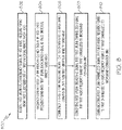
- Figure 7 is a flow diagram illustrating a method 700 of operating a distributed base station radio system, according to the claimed invention.
- Method 700 begins at block 702 with receiving a first downlink channelized signal for a first radio frequency band from a first channelized radio frequency source at a first channelized to broadband conversion unit.
- the channelized radio frequency source is a base band unit of a wireless access base station.
- the first channelized radio frequency source is at least one of a Common Public Radio Interface (CPRI) base station interface and an Open Base Station Architecture Initiative (OBSAI) base station interface.
- CPRI Common Public Radio Interface
- OBSAI Open Base Station Architecture Initiative
- the first downlink channelized data is formatted according to at least one of a Common Public Radio Interface (CPRI) standard and an Open Base Station Architecture Initiative (OBSAI) standard.
- CPRI Common Public Radio Interface
- OBSAI Open Base Station Architecture Initiative
- Method 700 proceeds to block 704 with converting the first downlink channelized signal into a first downlink broadband signal at the first channelized to broadband conversion unit.
- Method 700 proceeds to block 706 with communicating the first downlink broadband signal to a first universal remote radio head from the first channelized to broadband conversion unit 706.
- Method 700 proceeds to block 708 with frequency converting the first downlink broadband signal into a first downlink radio frequency signal at the first universal remote radio head.
- Method 700 proceeds to block 710 with transmitting a first downlink radio frequency signal in the first radio frequency band to a first subscriber unit at the first universal remote radio head.
- Method 700 further includes receiving second downlink channelized data for a second radio frequency band from a second channelized radio frequency source at a second channelized to broadband conversion unit.
- Method 700 further includes receiving the first downlink broadband signal from the first channelized to broadband conversion unit at a switch; receiving the second downlink broadband signal from the second channelized to broadband conversion unit at the switch; aggregating the first downlink broadband signal with the second downlink broadband signal into an aggregate downlink broadband signal; and communicating the aggregate downlink broadband signal from the switch to the first universal remote radio head.
- Method 700 further includes extracting the first downlink broadband signal from the aggregate downlink broadband signal at the first universal remote radio head.
- Method 700 further includes receiving second downlink channelized data for a second radio frequency band from a second channelized radio frequency source at a second channelized to broadband conversion unit; converting the second downlink channelized data into a second downlink broadband signal; communicating the second downlink broadband signal to the first universal remote radio head from the second channelized to broadband conversion unit; frequency converting the second downlink broadband signal into second downlink radio frequency signals in the second radio frequency band at the first universal remote radio head; and transmitting the second downlink radio frequency signals in the second radio frequency band to at least one subscriber unit at the first universal remote radio head.
- frequency converting the first downlink broadband signal into first downlink radio frequency signals in the first radio frequency band occurs at a first frequency converter of the first universal remote radio head; frequency converting the second downlink broadband signal into second downlink radio frequency signals in the second radio frequency band occurs at a second frequency converter of the first universal remote radio head; transmitting the first downlink radio frequency signals in the first radio frequency band to a first subscriber unit at the first universal remote radio head occurs at a first power amplifier, radio frequency transceiver, and antenna set of the first universal remote radio head; and transmitting the second downlink radio frequency signals in the second radio frequency band to at least one subscriber unit at the first universal remote radio head occurs at a second power amplifier, radio frequency transceiver, and antenna set of the first universal remote radio head.
- frequency converting the first downlink broadband signal into first downlink radio frequency signals in the first radio frequency band occurs at a first frequency converter of the first universal remote radio head; frequency converting the second downlink broadband signal into second downlink radio frequency signals in the second radio frequency band occurs at a second frequency converter of the first universal remote radio head; and transmitting both the first downlink radio frequency signals in the first radio frequency band and the second downlink radio frequency signals in the second radio frequency band occurs at a single power amplifier, radio frequency transceiver, and antenna set.
- frequency converting both the first downlink broadband signal into the first downlink radio frequency signals in the first radio frequency band and the second downlink broadband signals into the second downlink radio frequency signals in the second radio frequency band occurs at a single radio frequency converter; and transmitting both the first downlink radio frequency signals in the first radio frequency band and the second downlink radio frequency signals in the second radio frequency band occurs at a single power amplifier, radio frequency transceiver, and antenna set.
- Method 700 further includes receiving second downlink channelized data for a second radio frequency band from a second channelized radio frequency source at a second channelized to broadband conversion unit; converting the second downlink channelized data into a second downlink broadband signal; communicating the second downlink broadband signal to a second universal remote radio head from the second channelized to broadband conversion unit; frequency converting the second downlink broadband signal into second downlink radio frequency signals in the second radio frequency band at the second universal remote radio head; and transmitting the second downlink radio frequency signals in the second radio frequency band to at least one subscriber unit at the second universal remote radio head.
- Figure 8 is a flow diagram illustrating a method 800 of operating a distributed base station radio system, according to the claimed invention.
- Method 800 begins at block 802 with receiving a first uplink radio frequency signal in a first radio frequency band from a first subscriber unit at a first universal remote radio head.
- Method 800 proceeds to block 804 with frequency converting the first uplink radio frequency signal in the first radio frequency band into a first uplink broadband signal at a first universal remote radio head 804.
- Exemplary method 800 proceeds to block 806 with communicating the first uplink broadband signal to a first channelized to broadband conversion unit from the first universal remote radio head.
- Method 800 proceeds to block 808 with converting the first uplink broadband signal into a first uplink channelized signal for the first radio frequency band at the first channelized to broadband conversion unit 808.
- Method 800 proceeds to block 810 with communicating the first uplink channelized signal for the first radio frequency band to the first channelized radio frequency source at the first channelized to broadband conversion unit.
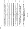
- FIG. 9 is a flow diagram illustrating an exemplary embodiment of a method 900 of operating a universal remote radio head.
- Exemplary method 900 begins at block 902 with receiving a downlink broadband signal having data for a radio frequency band from a remote channelized to broadband conversion module at the universal remote radio head.
- Exemplary method 900 proceeds to block 904 with frequency converting the downlink broadband signal into a downlink radio frequency signal in the radio frequency band at the universal remote radio head.
- Exemplary method 900 proceeds to block 906 with transmitting the downlink radio frequency signal in the radio frequency band to a subscriber unit at the universal remote radio head.
- Exemplary method 900 proceeds to block 908 with receiving an uplink radio frequency signal in the radio frequency band from the subscriber unit at the universal remote radio head.
- Exemplary method 900 proceeds to block 910 with frequency converting the uplink radio frequency signal in the radio frequency band into an uplink broadband signal at the universal remote radio head.
- Exemplary method 900 proceeds to block 912 with communicating the uplink broadband signal to the remote channelized to broadband conversion module at the universal remote radio head.
- FIG. 10 is a flow diagram illustrating an exemplary embodiment of a method 1000 of operating a channelized to broadband conversion unit.
- Exemplary method 1000 begins at block 1002 with receiving a downlink channelized signal for a radio frequency band from a channelized radio frequency source at a channelized to broadband conversion unit.
- the channelized radio frequency source is a base band unit of a wireless access base station.
- the first channelized radio frequency source is at least one of a Common Public Radio Interface (CPRI) base station interface, an Open Base Station Architecture Initiative (OBSAI) base station interface, and an Open Radio Interface (ORI) base station interface.
- CPRI Common Public Radio Interface
- OBSAI Open Base Station Architecture Initiative
- ORI Open Radio Interface
- the first downlink channelized data is formatted according to at least one of a Common Public Radio Interface (CPRI) standard, an Open Base Station Architecture Initiative (OBSAI) standard, and a Open Radio Interface (ORI) standard.
- CPRI Common Public Radio Interface
- OBSAI Open Base Station Architecture Initiative
- ORI Open Radio Interface
- Exemplary method 1000 proceeds to block 1004 with converting the downlink channelized signal into a downlink broadband signal at the channelized to broadband conversion unit.
- Exemplary method 1000 proceeds to block 1006 with communicating the downlink broadband signal to a universal remote radio head at the channelized to broadband conversion unit.
- Exemplary method 1000 proceeds to block 1008 with receiving an uplink broadband signal from the universal remote radio head at the channelized to broadband conversion unit.
- Exemplary method 1000 proceeds to block 1010 with converting the uplink broadband signal into an uplink channelized signal for the radio frequency band at the channelized to broadband conversion unit.
- Exemplary method 1000 proceeds to block 1012 with communicating the uplink channelized signal to the channelized radio frequency source at the channelized to broadband conversion unit.
- Embodiments of processors described herein include or function with software programs, firmware or other computer readable instructions for carrying out various methods, process tasks, calculations, and control functions, used in the components of the systems described above.
- the computer readable medium can be implemented as any available media that can be accessed by a general purpose or special purpose computer or processor, or any programmable logic device.
- Suitable processor-readable media may include storage or memory media such as magnetic or optical media.
- storage or memory media may include conventional hard disks, Compact Disk - Read Only Memory (CD-ROM), volatile or non-volatile media such as Random Access Memory (RAM) (including, but not limited to, Synchronous Dynamic Random Access Memory (SDRAM), Double Data Rate (DDR) RAM, RAMBUS Dynamic RAM (RDRAM), Static RAM (SRAM), etc.), Read Only Memory (ROM), Electrically Erasable Programmable ROM (EEPROM), and flash memory, etc.
- RAM Random Access Memory
- SDRAM Synchronous Dynamic Random Access Memory
- DDR Double Data Rate
- RDRAM RAMBUS Dynamic RAM
- SRAM Static RAM
- ROM Read Only Memory
- EEPROM Electrically Erasable Programmable ROM
- flash memory etc.
- Suitable processor-readable media may also include transmission media such as electrical, electromagnetic, or digital signals, conveyed via a communication medium such as a network and/or a wireless link.
Landscapes
- Engineering & Computer Science (AREA)
- Signal Processing (AREA)
- Computer Networks & Wireless Communication (AREA)
- Multimedia (AREA)
- Mobile Radio Communication Systems (AREA)
Claims (15)
- Système radio de station de base (100) réparti, comprenant :une première unité de conversion canaux vers large bande (102), configurée pour recevoir (702) des premières données multiplexées numériques de liaison descendante spécifiques à un premier canal représentant une première bande radioélectrique d'une première source radioélectrique découpée en canaux (110) ;dans lequel la première unité de conversion canaux vers large bande (102) est configurée en outre pour convertir en fréquence (704) les premières données multiplexées numériques de liaison descendante, en un premier signal à large bande de liaison descendante ;une seconde unité de conversion canaux vers large bande (102), configurée pour recevoir des secondes données multiplexées numériques de liaison descendante spécifiques à un second canal représentant une seconde bande radioélectrique d'une seconde source radioélectrique découpée en canaux (110) ;dans lequel la seconde unité de conversion canaux vers large bande (102) est configurée en outre pour convertir en fréquence (704) les secondes données multiplexées numériques de liaison descendante, en un second signal à large bande de liaison descendante ;un commutateur (124) couplé en communication entre la première unité de conversion canaux vers large bande (102) et la seconde unité de conversion canaux vers large bande (102), configuré pour recevoir le premier signal à large bande de liaison descendante et le second signal à large bande de liaison descendante, et pour combiner le premier signal à large bande de liaison descendante et le second signal à large bande de liaison descendante, en un signal à large bande de liaison descendante global, le signal à large bande de liaison descendante global présentant une pluralité de canaux dans des emplacements qui ne se chevauchent pas, qui représentent l'emplacement de chacun de la pluralité de canaux dans une partie du spectre radioélectrique ;une première tête radio distante universelle (104) couplée en communication au commutateur (124) ;dans lequel la première unité de conversion canaux vers large bande (102), est configurée en outre pour communiquer (706) le signal à large bande de liaison descendante global, à la première tête radio distante universelle (104) ;dans lequel la première tête radio distante universelle (104) est configurée pour recevoir le signal à large bande de liaison descendante global ;dans lequel la première tête radio distante universelle (104) est configurée en outre pour extraire le premier signal à large bande de liaison descendante, du signal à large bande de liaison descendante global ;dans lequel la première tête radio distante universelle (104) est configurée en outre pour convertir en fréquence (708) le premier signal à large bande de liaison descendante, en premiers signaux radioélectriques analogiques de liaison descendante dans la première bande radioélectrique ; etdans lequel la première tête radio distante universelle (104) est configurée en outre pour transmettre (710) les premiers signaux radioélectriques analogiques de liaison descendante dans la première bande radioélectrique, à une première unité d'abonné (118).
- Système radio de station de base (100) réparti, comprenant :une première tête radio distante universelle (104) configurée pour recevoir (800) des premiers signaux radioélectriques analogiques de liaison montante dans une première bande radioélectrique, en provenance d'une première unité d'abonné (118), et des seconds signaux radioélectriques analogiques de liaison montante dans une seconde bande radioélectrique, en provenance d'une seconde unité d'abonné (118) ;dans lequel la première tête radio distante universelle (104) est configurée en outre pour convertir en fréquence (804) les premiers signaux radioélectriques analogiques de liaison montante dans la première bande radioélectrique, en un premier signal à large bande de liaison montante, pour convertir en fréquence les seconds signaux radioélectriques analogiques de liaison montante dans la seconde bande radioélectrique, en un second signal à large bande de liaison montante, et pour combiner le premier signal à large bande de liaison montante avec le second signal à large bande de liaison montante, en un signal à large bande de liaison montante global, le signal à large bande de liaison montante global présentant une pluralité de canaux dans des emplacements qui ne se chevauchent pas, qui représentent l'emplacement de chacun de la pluralité de canaux dans une partie du spectre radioélectrique ;une première unité de conversion large bande vers canaux (102) couplée en communication à la première tête radio distante universelle (104) ;dans lequel la première tête radio distante universelle (104), est configurée en outre pour communiquer (806) le signal à large bande de liaison montante global, à la première unité de conversion large bande vers canaux (102) ;dans lequel la première unité de conversion large bande vers canaux (102) est configurée en outre pour recevoir le signal à large bande de liaison montante global ;dans lequel la première unité de conversion large bande vers canaux (102) est configurée en outre pour extraire le premier signal à large bande de liaison montante, du signal à large bande de liaison montante global ;dans lequel la première unité de conversion large bande vers canaux (102) est configurée en outre pour convertir en fréquence (808) le premier signal à large bande de liaison montante, en premières données multiplexées numériques de liaison montante spécifiques à un premier canal représentant la première bande radioélectrique ; etdans lequel la première unité de conversion large bande vers canaux (102) est configurée en outre pour communiquer (810) les premières données multiplexées numériques de liaison montante de la première bande radioélectrique, à une première interface radioélectrique découpée en canaux (110).
- Système radio de station de base (100) réparti selon la revendication 2,dans lequel la première tête radio distante universelle (104) est couplée en outre en communication à une seconde unité de conversion large bande vers canaux (102) ;dans lequel la première tête radio distante universelle (104), est configurée en outre pour communiquer (806) le signal à large bande de liaison montante global, à la seconde unité de conversion large bande vers canaux (102) ;dans lequel la seconde unité de conversion large bande vers canaux (102), est configurée en outre pour recevoir le signal à large bande de liaison montante global, en provenance de la première tête radio distante universelle (104) ;dans lequel la seconde unité de conversion large bande vers canaux (102) est configurée en outre pour extraire le second signal à large bande de liaison montante, du signal à large bande de liaison montante global ;dans lequel la seconde unité de conversion large bande vers canaux (102) est configurée en outre pour convertir en fréquence (808) le second signal à large bande de liaison montante de la seconde bande radioélectrique, en secondes données multiplexées numériques de liaison montante ; etdans lequel la seconde unité de conversion large bande vers canaux (102) est configurée en outre pour communiquer (810) les secondes données multiplexées numériques de liaison montante de la seconde bande radioélectrique, à une deuxième interface radioélectrique découpée en canaux (110).
- Système radio de station de base (100) réparti selon la revendication 3,
dans lequel la première tête radio distante universelle (104) est configurée pour combiner le premier signal à large bande de liaison montante avec le second signal à large bande de liaison montante, en un signal à large bande de liaison montante global, grâce à l'une au moins d'une opération d'addition et de multiplexage. - Système radio de station de base (100) réparti selon la revendication 3,dans lequel la première tête radio distante universelle (104) comprend un seul ensemble émetteur - récepteur radioélectrique et antenne (116), configuré pour recevoir la première bande radioélectrique et la seconde bande radioélectrique ; etdans lequel la première tête radio distante universelle (104) comprend un seul convertisseur radioélectrique (604) configuré pour convertir en fréquence les premiers signaux radioélectriques analogiques de liaison montante dans la première bande radioélectrique, en un premier signal à large bande de liaison montante, et les seconds signaux radioélectriques analogiques de liaison montante dans la seconde bande radioélectrique, en un second signal à large bande de liaison montante.
- Système radio de station de base (100) réparti, comprenant :une première tête radio distante universelle (104) configurée pour recevoir (800) des premiers signaux radioélectriques analogiques de liaison montante dans une première bande radioélectrique, en provenance d'une première unité d'abonné (118) ;dans lequel la première tête radio distante universelle (104) est configurée en outre pour convertir en fréquence (804) les premiers signaux radioélectriques analogiques de liaison montante dans la première bande radioélectrique, en un premier signal à large bande de liaison montante ;une seconde tête radio distante universelle (104) configurée pour recevoir des seconds signaux radioélectriques analogiques de liaison montante dans une seconde bande radioélectrique, en provenance d'une seconde unité d'abonné (118) ;dans lequel la seconde tête radio distante universelle (104) est configurée en outre pour convertir en fréquence les seconds signaux radioélectriques analogiques de liaison montante dans la seconde bande radioélectrique, en un second signal à large bande de liaison montante ;un commutateur (124) couplé en communication entre la première tête radio distante universelle (104) et la seconde tête radio distante universelle (104), configuré pour recevoir le premier signal à large bande de liaison montante et le second signal à large bande de liaison montante, et pour combiner le premier signal à large bande de liaison montante et le second signal à large bande de liaison montante, en un signal à large bande de liaison montante global, le signal à large bande de liaison montante global présentant une pluralité de canaux dans des emplacements qui ne se chevauchent pas, qui représentent l'emplacement de chacun de la pluralité de canaux dans une partie du spectre radioélectrique ;une première unité de conversion large bande vers canaux (102) couplée en communication au commutateur (124) ;dans lequel la première tête radio distante universelle (104), est configurée en outre pour communiquer (806) le signal à large bande de liaison montante global, à la première unité de conversion large bande vers canaux (102) ;dans lequel la première unité de conversion large bande vers canaux (102) est configurée en outre pour recevoir le signal à large bande de liaison montante global ;dans lequel la première unité de conversion large bande vers canaux (102) est configurée en outre pour extraire le premier signal à large bande de liaison montante, du signal à large bande de liaison montante global ;dans lequel la première unité de conversion large bande vers canaux (102) est configurée en outre pour convertir en fréquence (808) le premier signal à large bande de liaison montante, en premières données multiplexées numériques de liaison montante spécifiques à un premier canal représentant la première bande radioélectrique ; etdans lequel la première unité de conversion large bande vers canaux (102) est configurée en outre pour communiquer (810) les premières données multiplexées numériques de liaison montante de la première bande radioélectrique, à une première interface radioélectrique découpée en canaux.
- Système radio de station de base (100) réparti selon la revendication 6,dans lequel le commutateur (124) est couplé en outre en communication à une seconde unité de conversion large bande vers canaux (102) ;dans lequel le commutateur (124), est configuré en outre pour communiquer (806) le signal à large bande de liaison montante global, à la seconde unité de conversion large bande vers canaux (102) ;dans lequel la seconde unité de conversion large bande vers canaux (102) est configurée en outre pour recevoir le signal à large bande de liaison montante global en provenance du commutateur (124) ;dans lequel la seconde unité de conversion large bande vers canaux (102) est configurée en outre pour extraire le second signal à large bande de liaison montante, du signal à large bande de liaison montante global ;dans lequel la seconde unité de conversion large bande vers canaux (102) est configurée en outre pour convertir en fréquence (808) le second signal à large bande de liaison montante de la seconde bande radioélectrique, en secondes données multiplexées numériques de liaison montante ; etdans lequel la seconde unité de conversion large bande vers canaux (102) est configurée en outre pour communiquer (810) les secondes données multiplexées numériques de liaison montante de la seconde bande radioélectrique, à une deuxième interface radioélectrique découpée en canaux (110).
- Première unité de conversion canaux vers large bande (102) comprenant :une première interface configurée pour recevoir (702) des premières données multiplexées numériques de liaison descendante spécifiques à un premier canal représentant une première bande radioélectrique, en provenance d'une première source radioélectrique découpée en canaux (110), couplée à la première unité de conversion canaux vers large bande (102) ;une deuxième interface configurée pour recevoir des secondes données multiplexées numériques de liaison descendante spécifiques à un second canal représentant une seconde bande radioélectrique, en provenance d'une seconde source radioélectrique découpée en canaux (110), couplée à la première unité de conversion canaux vers large bande (102) ;un convertisseur de fréquence (604) configuré pour convertir (704) les premières données multiplexées numériques de liaison descendante, en un premier signal à large bande de liaison descendante, et les secondes données multiplexées numériques de liaison descendante, en un second signal à large bande de liaison descendante ;un duplexeur (608) couplé en communication au convertisseur de fréquence (604), configuré pour recevoir le premier signal à large bande de liaison descendante et le second signal à large bande de liaison descendante, et pour combiner le premier signal à large bande de liaison descendante et le second signal à large bande de liaison descendante, en un signal à large bande de liaison descendante global, le signal à large bande de liaison descendante global présentant une pluralité de canaux dans des emplacements qui ne se chevauchent pas, qui représentent l'emplacement de chacun de la pluralité de canaux dans une partie du spectre radioélectrique ; etune troisième interface configurée pour communiquer (706) le premier signal à large bande de liaison descendante à une première tête radio distante universelle (104).
- Unité de conversion large bande vers canaux (102) comprenant :une première interface configurée pour recevoir (806) un signal à large bande de liaison montante global, le signal à large bande de liaison montante global présentant une pluralité de canaux dans des emplacements qui ne se chevauchent pas, qui représentent l'emplacement de chacun de la pluralité de canaux dans une partie du spectre radioélectrique ;dans lequel l'unité de conversion large bande vers canaux (102) est configurée pour extraire un premier signal à large bande de liaison montante, du signal à large bande de liaison montante global ;un convertisseur de fréquence (604) configuré pour convertir en fréquence (808) le premier signal à large bande de liaison montante, en premières données multiplexées numériques de liaison montante spécifiques à un premier canal représentant une première bande radioélectrique ; etune deuxième interface configurée pour communiquer (810) les premières données multiplexées numériques de liaison montante de la première bande radioélectrique, à une première interface radioélectrique découpée en canaux (110), couplée à l'unité de conversion large bande vers canaux (102).
- Système radio de station de base (100) réparti selon la revendication 1 ou 2, ou première unité de conversion canaux vers large bande (102) selon la revendication 8 ou 9,dans lequel la première source radioélectrique découpée en canaux (110), ou la première interface radioélectrique découpée en canaux (110), est l'une au moins d'une interface de station de base de radio publique commune, CPRI, d'une interface de station de base d'initiative d'architecture de station de base ouverte, OBSAI, et d'une interface d'interface de radio ouverte, ORI ; etdans lequel les premières données multiplexées numériques de liaison descendante, ou les premières données multiplexées numériques de liaison montante, sont formatées selon l'une au moins d'une norme d'interface radio publique commune, CPRI, d'une norme d'initiative d'architecture de station de base ouverte, OBSAI, et d'une norme d'interface de radio ouverte, ORI.
- Système radio de station de base (100) réparti selon la revendication 1 ou 2, ou première unité de conversion canaux vers large bande (102) selon la revendication 8, ou unité de conversion large bande vers canaux (102) selon la revendication 9,
dans lequel la première source radioélectrique découpée en canaux (110), ou la première interface radioélectrique découpée en canaux (110), est une unité en bande de base d'une station de base à accès sans fil. - Première tête radio distante universelle (104) comprenant :une interface configurée pour recevoir (706) un signal à large bande de liaison descendante global, le signal à large bande de liaison descendante global présentant une pluralité de canaux dans des emplacements qui ne se chevauchent pas, qui représentent l'emplacement de chacun de la pluralité de canaux dans une partie du spectre radioélectrique ;dans lequel la première tête radio distante universelle (104) est configurée pour extraire un premier signal à large bande de liaison descendante, du signal à large bande de liaison descendante global ;un convertisseur de fréquence (604) configuré pour convertir en fréquence (708) le premier signal à large bande de liaison descendante, en premiers signaux radioélectriques analogiques de liaison descendante dans une première bande de fréquence ; etune paire émetteur - récepteur radioélectrique et antenne (116), configurée pour transmettre (710) les premiers signaux radioélectriques analogiques de liaison descendante dans la première bande de fréquence, à une première unité d'abonné (118).
- Première tête radio distante universelle (104) comprenant :une paire émetteur - récepteur radioélectrique et antenne (116), configurée pour recevoir (802) un premier signal radioélectrique analogique de liaison montante dans une première bande radioélectrique, en provenance d'une première unité d'abonné (118), et un second signal radioélectrique analogique de liaison montante dans une seconde bande radioélectrique, en provenance d'une seconde unité d'abonné (118) ;un convertisseur de fréquence (604) configuré pour convertir en fréquence (804) le premier signal radioélectrique analogique de liaison montante dans la première bande radioélectrique, en un premier signal à large bande de liaison montante, pour convertir en fréquence le second signal radioélectrique analogique de liaison montante dans la seconde bande radioélectrique, en un second signal à large bande de liaison montante, et pour combiner le premier signal à large bande de liaison montante avec le second signal à large bande de liaison montante, en un signal à large bande de liaison montante global, le signal à large bande de liaison montante global présentant une pluralité de canaux dans des emplacements qui ne se chevauchent pas, qui représentent l'emplacement de chacun de la pluralité de canaux dans une partie du spectre radioélectrique ; etune première interface configurée pour communiquer (806) le premier signal à large bande de liaison montante, à une première unité de conversion canaux vers large bande distante (102).
- Système radio de station de base (100) réparti selon la revendication 1 ou 2 ou 6, ou première unité de conversion canaux vers large bande (102) selon la revendication 8, ou unité de conversion large bande vers canaux (102) selon la revendication 9, ou première tête radio distante universelle (104) selon la revendication 12 ou 13,
dans lequel l'un au moins du premier signal à large bande de liaison descendante, du premier signal à large bande de liaison montante, du second signal à large bande de liaison descendante, du second signal à large bande de liaison montante, du signal à large bande de liaison montante global, et de l'autre signal à large bande de liaison montante, est un signal numérique. - Système radio de station de base (100) réparti selon la revendication 1 ou 2 ou 6, ou première unité de conversion canaux vers large bande (102) selon la revendication 8, ou unité de conversion large bande vers canaux (102) selon la revendication 9, ou première tête radio distante universelle (104) selon la revendication 12 ou 13,
dans lequel l'un au moins du premier signal à large bande de liaison descendante, du premier signal à large bande de liaison montante, du second signal à large bande de liaison descendante, du second signal à large bande de liaison montante, du signal à large bande de liaison montante global, et de l'autre signal à large bande de liaison montante, est un signal analogique.
Priority Applications (1)
| Application Number | Priority Date | Filing Date | Title |
|---|---|---|---|
| EP22186582.7A EP4099797A1 (fr) | 2013-02-22 | 2014-02-21 | Tête radio distante universelle |
Applications Claiming Priority (3)
| Application Number | Priority Date | Filing Date | Title |
|---|---|---|---|
| US201361768038P | 2013-02-22 | 2013-02-22 | |
| EP14754119.7A EP2959651B1 (fr) | 2013-02-22 | 2014-02-21 | Tête radio distante universelle |
| PCT/US2014/017648 WO2014130797A1 (fr) | 2013-02-22 | 2014-02-21 | Tête radio distante universelle |
Related Parent Applications (1)
| Application Number | Title | Priority Date | Filing Date |
|---|---|---|---|
| EP14754119.7A Division EP2959651B1 (fr) | 2013-02-22 | 2014-02-21 | Tête radio distante universelle |
Related Child Applications (1)
| Application Number | Title | Priority Date | Filing Date |
|---|---|---|---|
| EP22186582.7A Division EP4099797A1 (fr) | 2013-02-22 | 2014-02-21 | Tête radio distante universelle |
Publications (2)
| Publication Number | Publication Date |
|---|---|
| EP3364713A1 EP3364713A1 (fr) | 2018-08-22 |
| EP3364713B1 true EP3364713B1 (fr) | 2022-08-03 |
Family
ID=51388050
Family Applications (3)
| Application Number | Title | Priority Date | Filing Date |
|---|---|---|---|
| EP18166380.8A Active EP3364713B1 (fr) | 2013-02-22 | 2014-02-21 | Tête radio distante universelle |
| EP14754119.7A Active EP2959651B1 (fr) | 2013-02-22 | 2014-02-21 | Tête radio distante universelle |
| EP22186582.7A Pending EP4099797A1 (fr) | 2013-02-22 | 2014-02-21 | Tête radio distante universelle |
Family Applications After (2)
| Application Number | Title | Priority Date | Filing Date |
|---|---|---|---|
| EP14754119.7A Active EP2959651B1 (fr) | 2013-02-22 | 2014-02-21 | Tête radio distante universelle |
| EP22186582.7A Pending EP4099797A1 (fr) | 2013-02-22 | 2014-02-21 | Tête radio distante universelle |
Country Status (6)
| Country | Link |
|---|---|
| US (4) | US9178636B2 (fr) |
| EP (3) | EP3364713B1 (fr) |
| KR (1) | KR102228617B1 (fr) |
| CN (2) | CN105191241B (fr) |
| CA (1) | CA2901666A1 (fr) |
| WO (1) | WO2014130797A1 (fr) |
Families Citing this family (27)
| Publication number | Priority date | Publication date | Assignee | Title |
|---|---|---|---|---|
| US9525488B2 (en) | 2010-05-02 | 2016-12-20 | Corning Optical Communications LLC | Digital data services and/or power distribution in optical fiber-based distributed communications systems providing digital data and radio frequency (RF) communications services, and related components and methods |
| EP2606707A1 (fr) | 2010-08-16 | 2013-06-26 | Corning Cable Systems LLC | Grappes d'antennes distantes, et systèmes, composants et procédés associés adaptés pour prendre en charge une propagation de signaux de données numériques entre des unités d'antennes distantes |
| US9252874B2 (en) | 2010-10-13 | 2016-02-02 | Ccs Technology, Inc | Power management for remote antenna units in distributed antenna systems |
| CN203504582U (zh) | 2011-02-21 | 2014-03-26 | 康宁光缆系统有限责任公司 | 一种分布式天线系统及用于在其中分配电力的电源装置 |
| BR112014010895B1 (pt) | 2011-11-07 | 2022-06-14 | Dali Systems Co., Ltd | Sistema e método para gerenciar uso de recurso em um sistema de antena distribuída |
| US9178636B2 (en) | 2013-02-22 | 2015-11-03 | Adc Telecommunications, Inc. | Universal remote radio head |
| JP2017505085A (ja) * | 2013-12-23 | 2017-02-09 | ダリ システムズ カンパニー リミテッド | 分散型アンテナシステムのデジタルマルチプレクサ |
| US20170250927A1 (en) | 2013-12-23 | 2017-08-31 | Dali Systems Co. Ltd. | Virtual radio access network using software-defined network of remotes and digital multiplexing switches |
| US9686379B2 (en) | 2014-06-11 | 2017-06-20 | Commscope Technologies Llc | Bitrate efficient transport through distributed antenna systems |
| US10659163B2 (en) | 2014-09-25 | 2020-05-19 | Corning Optical Communications LLC | Supporting analog remote antenna units (RAUs) in digital distributed antenna systems (DASs) using analog RAU digital adaptors |
| US10383172B2 (en) * | 2014-09-30 | 2019-08-13 | Nokia Of America Corporation | Method and apparatus for a single unit small, low-power base station supporting both metro cell outdoor (MCO) and metro radio outdoor (MRO) operations |
| WO2016071902A1 (fr) | 2014-11-03 | 2016-05-12 | Corning Optical Communications Wireless Ltd. | Antennes planes monopôles multibandes configurées pour faciliter une isolation radiofréquence (rf) améliorée dans un système d'antennes entrée multiple sortie multiple (mimo) |
| WO2016075696A1 (fr) | 2014-11-13 | 2016-05-19 | Corning Optical Communications Wireless Ltd. | Systèmes d'antennes distribuées (das) analogiques prenant en charge une distribution de signaux de communications numériques interfacés provenant d'une source de signaux numériques et de signaux de communications radiofréquences (rf) analogiques |
| WO2016098109A1 (fr) | 2014-12-18 | 2016-06-23 | Corning Optical Communications Wireless Ltd. | Modules d'interface numérique (dim) pour une distribution flexible de signaux de communication numériques et/ou analogiques dans des réseaux d'antennes distribuées (das) analogiques étendus |
| WO2016098111A1 (fr) | 2014-12-18 | 2016-06-23 | Corning Optical Communications Wireless Ltd. | Modules d'interface numérique-analogique (daim) pour une distribution flexible de signaux de communications numériques et/ou analogiques dans des systèmes étendus d'antennes distribuées analogiques (das) |
| EP3269118B8 (fr) | 2015-03-11 | 2021-03-17 | CommScope, Inc. of North Carolina | Réseau d'accès radio distribué comprenant une liaison de raccordement aux sites cellulaires adaptative |
| US9712343B2 (en) | 2015-06-19 | 2017-07-18 | Andrew Wireless Systems Gmbh | Scalable telecommunications system |
| US10608734B2 (en) | 2015-10-22 | 2020-03-31 | Phluido, Inc. | Virtualization and orchestration of a radio access network |
| WO2018017468A1 (fr) | 2016-07-18 | 2018-01-25 | Phluido, Inc. | Synchronisation d'unités radio dans des réseaux d'accès radio |
| WO2019100073A1 (fr) * | 2017-11-20 | 2019-05-23 | Commscope Technologies Llc | Interconnexion de composants modulaires pour former une unité distante à utiliser dans un système d'antennes distribuées |
| CN111406371B (zh) * | 2017-11-28 | 2023-09-01 | 瑞典爱立信有限公司 | 改进的无线电接入网络节点技术 |
| KR102322042B1 (ko) * | 2017-11-29 | 2021-11-08 | 한국전자통신연구원 | 비선형 노이즈에 의한 광 신호의 왜곡을 방지하는 호스트 장치 및 상기 호스트 장치를 포함하는 분산형 안테나 시스템 |
| US12016084B2 (en) | 2018-01-04 | 2024-06-18 | Commscope Technologies Llc | Management of a split physical layer in a radio area network |
| CN112913278B (zh) | 2018-10-25 | 2023-08-01 | 康普技术有限责任公司 | 用于集中式无线电接入网络的多载波无线电点 |
| US11372180B2 (en) * | 2020-01-31 | 2022-06-28 | Ciena Corporation | Modular networking hardware platform |
| WO2021219224A1 (fr) * | 2020-04-30 | 2021-11-04 | Telefonaktiebolaget Lm Ericsson (Publ) | Interface améliorée dans des radios connectées en série |
| KR20230031227A (ko) | 2020-06-30 | 2023-03-07 | 콤스코프 테크놀로지스, 엘엘씨 | 다수의 기능 분할, 다수의 무선 인터페이스 프로토콜, 다수의 세대의 무선 접속 기술 및 다수의 무선 주파수 대역을 지원하는 통합 원격 유닛을 갖는 개방형 무선 접속망 |
Citations (1)
| Publication number | Priority date | Publication date | Assignee | Title |
|---|---|---|---|---|
| EP0985324B1 (fr) * | 1997-06-13 | 2006-04-12 | Telefonaktiebolaget LM Ericsson (publ) | Reutilisation d'un canal de commande physique dans un systeme de radiocommunications cellulaire distribue |
Family Cites Families (150)
| Publication number | Priority date | Publication date | Assignee | Title |
|---|---|---|---|---|
| US1787854A (en) | 1926-10-28 | 1931-01-06 | Braun Otto | Carburetor |
| US1920858A (en) | 1928-02-16 | 1933-08-01 | Harter Hans | Process of converting gases rich in methane into more valuable products |
| US4183054A (en) | 1977-09-30 | 1980-01-08 | Harris Corporation | Digital, frequency-translated, plural-channel, vestigial sideband television communication system |
| US4451916A (en) | 1980-05-12 | 1984-05-29 | Harris Corporation | Repeatered, multi-channel fiber optic communication network having fault isolation system |
| NL8203600A (nl) | 1982-09-17 | 1984-04-16 | Philips Nv | Hoofdeinde en ontvanger voor een signaaldistributiesysteem. |
| US4691292A (en) | 1983-04-13 | 1987-09-01 | Rca Corporation | System for digital multiband filtering |
| DE3318774A1 (de) | 1983-05-24 | 1984-11-29 | ANT Nachrichtentechnik GmbH, 7150 Backnang | Verfahren zur uebertragung von digital codierten analogsignalen |
| US4628501A (en) | 1983-12-29 | 1986-12-09 | The United States Of America As Represented By The Secretary Of The Army | Optical communications systems |
| US5682256A (en) | 1988-11-11 | 1997-10-28 | British Telecommunications Public Limited Company | Communications system |
| US5193109A (en) | 1989-02-06 | 1993-03-09 | Pactel Corporation | Zoned microcell with sector scanning for cellular telephone system |
| CA2008900C (fr) | 1989-04-04 | 1998-01-20 | Ta-Shing Chu | Radio mobile microcellulaire a fibre optique |
| US4999831A (en) | 1989-10-19 | 1991-03-12 | United Telecommunications, Inc. | Synchronous quantized subcarrier multiplexer for digital transport of video, voice and data |
| GB9008162D0 (en) | 1990-04-10 | 1990-06-06 | British Telecomm | Signal distribution |
| EP0476569B1 (fr) | 1990-09-17 | 1996-12-18 | Nec Corporation | Système de communication mobile |
| GB2253770B (en) | 1991-01-15 | 1996-01-10 | Rogers Communications Inc | Radiotelephony system |
| US5809395A (en) | 1991-01-15 | 1998-09-15 | Rogers Cable Systems Limited | Remote antenna driver for a radio telephony system |
| US5802173A (en) | 1991-01-15 | 1998-09-01 | Rogers Cable Systems Limited | Radiotelephony system |
| US5243598A (en) | 1991-04-02 | 1993-09-07 | Pactel Corporation | Microcell system in digital cellular |
| US5321849A (en) | 1991-05-22 | 1994-06-14 | Southwestern Bell Technology Resources, Inc. | System for controlling signal level at both ends of a transmission link based on a detected valve |
| CA2067637C (fr) | 1991-07-29 | 1997-11-18 | John Lappington | Systeme de distribution de signaux de radiotelephonie via un reseau de television par cable |
| US5545397A (en) | 1991-10-23 | 1996-08-13 | Boron Biologicals, Inc. | Contrast agents and compositions for radiological imaging, and radiological imaging method utilizing same |
| US5461627A (en) | 1991-12-24 | 1995-10-24 | Rypinski; Chandos A. | Access protocol for a common channel wireless network |
| CA2058737C (fr) | 1992-01-03 | 1997-03-18 | Andrew S. Beasley | Systeme de repeteurs rf a amelioration dans l'utilisation simultanee des frequences pour telephones sans fil |
| CA2058736C (fr) | 1992-01-03 | 1995-02-14 | Andrew S. Beasley | Systeme de repeteurs rf repartis pour telephones sans fil |
| CA2069462A1 (fr) | 1992-01-09 | 1993-07-10 | Andrew S. Beasley | Repeteur rf a bruit reduit pour telephones sans fil |
| US5339184A (en) | 1992-06-15 | 1994-08-16 | Gte Laboratories Incorporated | Fiber optic antenna remoting for multi-sector cell sites |
| US5377255A (en) | 1992-07-14 | 1994-12-27 | Pcs Microcell International Inc. | RF repeaters for time division duplex cordless telephone systems |
| US5590173A (en) | 1992-08-05 | 1996-12-31 | Beasley; Andrew S. | Delay insensitive base station-to-handset interface for radio telephone systems |
| US5303287A (en) | 1992-08-13 | 1994-04-12 | Hughes Aircraft Company | Integrated personal/cellular communications system architecture |
| US5627879A (en) | 1992-09-17 | 1997-05-06 | Adc Telecommunications, Inc. | Cellular communications system with centralized base stations and distributed antenna units |
| US5404570A (en) | 1992-11-23 | 1995-04-04 | Telefonaktiebolaget L M Ericsson | Radio coverage in closed environments |
| US5390235A (en) | 1993-06-23 | 1995-02-14 | Pcs Microcell International, Inc. | Cordless telephone system and switching control method therefor |
| US5539730A (en) | 1994-01-11 | 1996-07-23 | Ericsson Ge Mobile Communications Inc. | TDMA/FDMA/CDMA hybrid radio access methods |
| CA2191721C (fr) | 1994-06-01 | 2003-05-20 | Ronald R. Carney | Station de base sans fil a large bande utilisant un bus a acces multiple a repartition dans le temps pour effectuer des connexions commutables avec des ressources modulateur/demodulateur |
| US5519691A (en) | 1994-06-03 | 1996-05-21 | At&T Corp. | Arrangement for and method of providing radio frequency access to a switching system |
| US5987014A (en) | 1994-07-14 | 1999-11-16 | Stanford Telecommunications, Inc. | Multipath resistant, orthogonal code-division multiple access system |
| CA2128842A1 (fr) | 1994-07-26 | 1996-01-27 | Andrew Beasley | Systeme de telephonie sans fil utilisant des lignes controlees par le central |
| US5634191A (en) | 1994-10-24 | 1997-05-27 | Pcs Microcell International, Inc. | Self-adjusting RF repeater arrangements for wireless telephone systems |
| CA2134365C (fr) | 1994-10-26 | 2000-10-03 | Andrew Beasley | Repeteur rf a deux etages a reglage automatique pour systemes de telephonie sans fil |
| KR0133338B1 (ko) | 1994-12-16 | 1998-04-21 | 양승택 | 위성중계기용 디지털 자동이득제어장치 |
| US5592480A (en) | 1995-03-13 | 1997-01-07 | Carney; Ronald R. | Wideband wireless basestation making use of time division multiple-access bus having selectable number of time slots and frame synchronization to support different modulation standards |
| US5822324A (en) | 1995-03-16 | 1998-10-13 | Bell Atlantic Network Services, Inc. | Simulcasting digital video programs for broadcast and interactive services |
| US5761619A (en) | 1995-03-23 | 1998-06-02 | Telefoanktiebolaget Lm Ericsson | Distributed telecommunications system |
| US5781541A (en) | 1995-05-03 | 1998-07-14 | Bell Atlantic Network Services, Inc. | CDMA system having time-distributed transmission paths for multipath reception |
| US5890055A (en) | 1995-07-28 | 1999-03-30 | Lucent Technologies Inc. | Method and system for connecting cells and microcells in a wireless communications network |
| CA2158386A1 (fr) | 1995-09-15 | 1997-03-16 | Andrew Beasley | Repeteurs rf pour systemes de telephonie mobile amrt |
| US5732076A (en) | 1995-10-26 | 1998-03-24 | Omnipoint Corporation | Coexisting communication systems |
| IT1281001B1 (it) | 1995-10-27 | 1998-02-11 | Cselt Centro Studi Lab Telecom | Procedimento e apparecchiatura per codificare, manipolare e decodificare segnali audio. |
| US6246675B1 (en) | 1995-11-14 | 2001-06-12 | Andrew Beasley | CDMA cordless telephone system and method of operation thereof |
| US5870392A (en) | 1995-12-28 | 1999-02-09 | Lucent Technologies Inc. | Microcell architecture |
| US6108113A (en) | 1995-12-29 | 2000-08-22 | Mci Communications Corporation | Method and system for transporting ancillary network data |
| CA2168681A1 (fr) | 1996-02-02 | 1997-08-03 | Andrew Beasley | Repeteurs rf pour telephones sans fil a multiplexage temporel n'utilisant pas de signaux de synchronisation |
| US6084889A (en) | 1996-02-14 | 2000-07-04 | Hitachi, Ltd. | ATM multiplexing apparatus, ATM demultiplexing apparatus, and communication network with the apparatus |
| US5970410A (en) | 1996-02-27 | 1999-10-19 | Airnet Communications Corp. | Cellular system plan using in band-translators to enable efficient deployment of high capacity base transceiver systems |
| CN1240192C (zh) | 1996-04-19 | 2006-02-01 | Lgc无线股份有限公司 | 在低带宽媒体上传输rf带宽内的rf信号的系统和方法 |
| US6157810A (en) | 1996-04-19 | 2000-12-05 | Lgc Wireless, Inc | Distribution of radio-frequency signals through low bandwidth infrastructures |
| US5907544A (en) | 1996-05-10 | 1999-05-25 | Rypinski; Chandos A. | Hub controller architecture and function for a multiple access-point wireless communication network |
| US5867485A (en) | 1996-06-14 | 1999-02-02 | Bellsouth Corporation | Low power microcellular wireless drop interactive network |
| US5914963A (en) | 1996-06-21 | 1999-06-22 | Compaq Computer Corporation | Clock skew reduction |
| US5805983A (en) | 1996-07-18 | 1998-09-08 | Ericsson Inc. | System and method for equalizing the delay time for transmission paths in a distributed antenna network |
| US5790529A (en) | 1996-08-01 | 1998-08-04 | Motorola, Inc. | Communications network node with switched channelizer architecture |
| US6205133B1 (en) | 1996-11-25 | 2001-03-20 | Ericsson Inc. | Flexible wideband architecture for use in radio communications systems |
| US5845199A (en) | 1996-12-05 | 1998-12-01 | Ericsson Inc. | Simulcasting system with diversity reception |
| GB2320653A (en) | 1996-12-23 | 1998-06-24 | Northern Telecom Ltd | Mobile Communications Network Using Alternative Protocols |
| US6034950A (en) | 1996-12-27 | 2000-03-07 | Motorola Inc. | System packet-based centralized base station controller |
| EP0876073A3 (fr) | 1997-05-01 | 2000-03-01 | AT&T Corp. | Téléphone à deux modes pour des réseaux sans fils et des réseaux cellulaires |
| AU8684098A (en) | 1997-07-31 | 1999-02-22 | Sapphire Communications, Inc. | Means and method for a synchronous network communications system |
| CA2215079A1 (fr) | 1997-09-09 | 1999-03-09 | Andrew S. Beasley | Systeme en boucle sans fil a acces ameliore |
| US6157659A (en) | 1997-12-19 | 2000-12-05 | Nortel Networks Corporation | Method of and apparatus for multiplexing and demultiplexing digital signal streams |
| EP1060570A1 (fr) | 1998-01-15 | 2000-12-20 | Interwave Communications Inc. | Station de base sans fil pour la desserte commune de terminaux multiples |
| US6591084B1 (en) | 1998-04-27 | 2003-07-08 | General Dynamics Decision Systems, Inc. | Satellite based data transfer and delivery system |
| US6667973B1 (en) | 1998-04-29 | 2003-12-23 | Zhone Technologies, Inc. | Flexible SONET access and transmission systems |
| US6768745B1 (en) | 1998-04-29 | 2004-07-27 | Zhone Technologies, Inc. | Flexible SONET access and transmission system |
| US6222660B1 (en) | 1998-06-09 | 2001-04-24 | Tektronix, Inc. | Adaptive power supply for avalanche photodiode |
| US6195385B1 (en) | 1998-06-30 | 2001-02-27 | Cisco Systems, Inc. | HTU-C clocking from a single source |
| US6226274B1 (en) | 1998-09-24 | 2001-05-01 | Omnipoint Corporation | Method and apparatus for multiple access communication |
| DE69831240T2 (de) | 1998-10-15 | 2006-06-01 | Lucent Technologies Inc. | Rekonfigurierbares faseroptisches Netzwerk für Drahtlose Übertragung |
| US6498936B1 (en) | 1999-01-22 | 2002-12-24 | Ericsson Inc. | Methods and systems for coding of broadcast messages |
| JP2002536908A (ja) | 1999-02-05 | 2002-10-29 | インターデイジタル テクノロジー コーポレーション | ケーブル損失自動補償手段を備える送受信局 |
| US6912230B1 (en) | 1999-02-05 | 2005-06-28 | Tecore | Multi-protocol wireless communication apparatus and method |
| EP1161820B1 (fr) | 1999-03-12 | 2006-04-19 | Aware, Inc. | Systeme et protocoles de modulation a porteuses multiples a debit adaptatif sans coupure |
| US6729929B1 (en) | 1999-03-17 | 2004-05-04 | Cisco Systems, Inc. | Method and apparatus for controlling wireless networks |
| JP2000333240A (ja) | 2000-03-24 | 2000-11-30 | Kokusai Electric Co Ltd | 移動体通信用光伝送システム |
| US6327299B1 (en) | 1999-08-31 | 2001-12-04 | Motorola, Inc. | Method and system for measuring and adjusting the quality of an orthogonal transmit diversity signal in a wireless communications system |
| US6917614B1 (en) | 1999-09-17 | 2005-07-12 | Arris International, Inc. | Multi-channel support for virtual private networks in a packet to ATM cell cable system |
| JP2001197012A (ja) | 1999-10-27 | 2001-07-19 | Toyo Commun Equip Co Ltd | 光伝送中継器及びこれを用いた中継システム |
| KR100316693B1 (ko) | 1999-12-22 | 2001-12-20 | 박종섭 | 이동통신 기지국의 rf블록 |
| US7302497B2 (en) | 2000-02-08 | 2007-11-27 | Telefonaktiebolaget Lm Ericsson (Publ) | Using internet protocol (IP) in radio access network |
| DE60139116D1 (de) | 2000-03-27 | 2009-08-13 | Opencell Corp | System zum Verteilen von Multiprotokoll-RF-Signalen |
| EP1269691B1 (fr) | 2000-03-29 | 2007-12-26 | OpenCell Corp. | Operations et architecture de maintenance pour systeme distribue multiprotocole |
| KR20020093947A (ko) | 2000-04-25 | 2002-12-16 | 콸콤 인코포레이티드 | 밀폐된 지역의 무선 주파수 커버리지 |
| US6704545B1 (en) | 2000-07-19 | 2004-03-09 | Adc Telecommunications, Inc. | Point-to-multipoint digital radio frequency transport |
| US6961388B2 (en) | 2001-02-01 | 2005-11-01 | Qualcomm, Incorporated | Coding scheme for a wireless communication system |
| US6771940B2 (en) | 2001-03-27 | 2004-08-03 | Northrop Grumman Corporation | Multi-channel peak power smoothing |
| US20020167954A1 (en) | 2001-05-11 | 2002-11-14 | P-Com, Inc. | Point-to-multipoint access network integrated with a backbone network |
| US6826163B2 (en) | 2001-06-08 | 2004-11-30 | Nextg Networks | Method and apparatus for multiplexing in a wireless communication infrastructure |
| US6826164B2 (en) | 2001-06-08 | 2004-11-30 | Nextg Networks | Method and apparatus for multiplexing in a wireless communication infrastructure |
| US7127175B2 (en) | 2001-06-08 | 2006-10-24 | Nextg Networks | Method and apparatus for multiplexing in a wireless communication infrastructure |
| US20020191565A1 (en) | 2001-06-08 | 2002-12-19 | Sanjay Mani | Methods and systems employing receive diversity in distributed cellular antenna applications |
| US6865390B2 (en) | 2001-06-25 | 2005-03-08 | Lucent Technologies Inc. | Cellular communications system featuring a central radio pool/traffic router |
| US6586863B2 (en) | 2001-06-28 | 2003-07-01 | Samsung Electro-Mechanics Co., Ltd. | Rosen type piezoelectric transformer with multiple output electrodes |
| JP4620295B2 (ja) | 2001-07-06 | 2011-01-26 | 株式会社日立国際電気 | 移動体通信用光伝送装置 |
| IT1403065B1 (it) * | 2010-12-01 | 2013-10-04 | Andrew Wireless Systems Gmbh | Distributed antenna system for mimo signals. |
| US7039399B2 (en) | 2002-03-11 | 2006-05-02 | Adc Telecommunications, Inc. | Distribution of wireless telephony and data signals in a substantially closed environment |
| US6831901B2 (en) | 2002-05-31 | 2004-12-14 | Opencell Corporation | System and method for retransmission of data |
| US7042394B2 (en) | 2002-08-14 | 2006-05-09 | Skipper Wireless Inc. | Method and system for determining direction of transmission using multi-facet antenna |
| US7221911B2 (en) | 2002-08-16 | 2007-05-22 | Wisair Ltd. | Multi-band ultra-wide band communication method and system |
| US20040037565A1 (en) | 2002-08-22 | 2004-02-26 | Robin Young | Transport of signals over an optical fiber using analog RF multiplexing |
| US20040053602A1 (en) | 2002-09-18 | 2004-03-18 | Wurzburg Francis L. | Low-cost interoperable wireless multi-application and messaging service |
| US20040198453A1 (en) | 2002-09-20 | 2004-10-07 | David Cutrer | Distributed wireless network employing utility poles and optical signal distribution |
| JP2004180220A (ja) | 2002-11-29 | 2004-06-24 | Hitachi Kokusai Electric Inc | 無線局システム |
| US8958789B2 (en) | 2002-12-03 | 2015-02-17 | Adc Telecommunications, Inc. | Distributed digital antenna system |
| US7103377B2 (en) | 2002-12-03 | 2006-09-05 | Adc Telecommunications, Inc. | Small signal threshold and proportional gain distributed digital communications |
| US7171244B2 (en) | 2002-12-03 | 2007-01-30 | Adc Telecommunications, Inc. | Communication system and method with gain control for signals from distributed antennas |
| US6785558B1 (en) | 2002-12-06 | 2004-08-31 | Lgc Wireless, Inc. | System and method for distributing wireless communication signals over metropolitan telecommunication networks |
| WO2004059934A1 (fr) | 2002-12-24 | 2004-07-15 | Pirelli & C. S.P.A. | Recepteur de station de base radio a filtrage numerique et frequence d'echantillonnage reduite |
| US7644177B2 (en) * | 2003-02-28 | 2010-01-05 | Cisco Technology, Inc. | Multicast-routing-protocol-independent realization of IP multicast forwarding |
| FI20030663A0 (fi) | 2003-05-02 | 2003-05-02 | Nokia Corp | Antennijärjestely ja tukiasema |
| US20060026017A1 (en) | 2003-10-28 | 2006-02-02 | Walker Richard C | National / international management and security system for responsible global resourcing through technical management to brige cultural and economic desparity |
| US8891519B2 (en) | 2004-04-05 | 2014-11-18 | Verizon Patent And Licensing Inc. | System and method for monitoring, controlling and provisioning a telecommunications access network |
| US20050250503A1 (en) | 2004-05-05 | 2005-11-10 | Cutrer David M | Wireless networks frequency reuse distance reduction |
| US7289972B2 (en) | 2004-06-25 | 2007-10-30 | Virginia Tech Intellectual Properties, Inc. | Cognitive radio engine based on genetic algorithms in a network |
| US7313415B2 (en) | 2004-11-01 | 2007-12-25 | Nextg Networks, Inc. | Communications system and method |
| US7205864B2 (en) | 2004-11-02 | 2007-04-17 | Nextg Networks, Inc. | Distributed matrix switch |
| CA2588781A1 (fr) | 2004-11-19 | 2006-05-26 | The Trustees Of The Stevens Institute Of Technology | Terminal a utilisateurs multiples avec capacite de connectabilite simultanee a de multiples canaux de communication |
| US7787854B2 (en) | 2005-02-01 | 2010-08-31 | Adc Telecommunications, Inc. | Scalable distributed radio network |
| US7489641B2 (en) * | 2005-04-25 | 2009-02-10 | Acterna | Data connection quality analysis apparatus and methods |
| US20070008939A1 (en) | 2005-06-10 | 2007-01-11 | Adc Telecommunications, Inc. | Providing wireless coverage into substantially closed environments |
| US8737454B2 (en) * | 2007-01-25 | 2014-05-27 | Adc Telecommunications, Inc. | Modular wireless communications platform |
| US8175649B2 (en) | 2008-06-20 | 2012-05-08 | Corning Mobileaccess Ltd | Method and system for real time control of an active antenna over a distributed antenna system |
| US8195224B2 (en) | 2008-05-13 | 2012-06-05 | Corning Mobileaccess Ltd | Multiple data services over a distributed antenna system |
| US8385373B2 (en) | 2008-06-24 | 2013-02-26 | Adc Telecommunications, Inc. | Method and apparatus for frame detection in a communications system |
| US8208414B2 (en) | 2008-06-24 | 2012-06-26 | Lgc Wireless, Inc. | System and method for configurable time-division duplex interface |
| US8213401B2 (en) * | 2009-01-13 | 2012-07-03 | Adc Telecommunications, Inc. | Systems and methods for IP communication over a distributed antenna system transport |
| CN101841748B (zh) | 2009-03-17 | 2013-06-12 | 中国移动通信集团公司 | 信号传输系统以及相关装置 |
| US8346091B2 (en) * | 2009-04-29 | 2013-01-01 | Andrew Llc | Distributed antenna system for wireless network systems |
| CN101998616B (zh) * | 2009-08-31 | 2014-05-14 | 国际商业机器公司 | 无线通信系统基站及其数据传输的同步方法 |
| DE102009052936B8 (de) * | 2009-11-12 | 2012-05-10 | Andrew Wireless Systems Gmbh | Master-Einheit, Remote-Einheit sowie Multiband-Übertragungssystem |
| KR101700956B1 (ko) * | 2010-01-29 | 2017-01-31 | 삼성전자주식회사 | 통신 시스템에서 단말의 위치를 식별하는 방법 및 장치 |
| US8576703B2 (en) * | 2010-03-19 | 2013-11-05 | Brocade Communications Systems, Inc. | Synchronization of multicast information using bicasting |
| KR101105193B1 (ko) * | 2010-04-15 | 2012-01-13 | 주식회사 이너트론 | 무선주파수 전력감시 모듈을 집적한 송수신 전단부를 포함하는 리모트 라디오 헤드 및 그의 무선주파수 전력감시 방법 |
| US8472579B2 (en) | 2010-07-28 | 2013-06-25 | Adc Telecommunications, Inc. | Distributed digital reference clock |
| KR20120018006A (ko) * | 2010-08-20 | 2012-02-29 | (주)씨맥스와이어리스 | 광대역 디지털 i/q 신호 전송 및 제어 방법 |
| US8649388B2 (en) * | 2010-09-02 | 2014-02-11 | Integrated Device Technology, Inc. | Transmission of multiprotocol data in a distributed antenna system |
| US8902769B1 (en) * | 2010-09-24 | 2014-12-02 | Quantenna Communications, Inc. | Method and apparatus for oversubscription control in a Wi-Fi home network |
| US9059778B2 (en) * | 2011-01-07 | 2015-06-16 | Integrated Device Technology Inc. | Frequency domain compression in a base transceiver system |
| KR101971584B1 (ko) * | 2011-06-29 | 2019-04-23 | 콤스코프 커넥티비티 엘엘씨 | 진화된 분산 안테나 시스템 |
| US8964641B2 (en) * | 2012-06-10 | 2015-02-24 | Cisco Technology, Inc. | System and method for transporting digital baseband streams in a network environment |
| CN202696592U (zh) * | 2012-07-30 | 2013-01-23 | 京信通信系统(广州)有限公司 | 一种收发信机装置、阵列天线装置及室内和室外覆盖系统 |
| US9178636B2 (en) | 2013-02-22 | 2015-11-03 | Adc Telecommunications, Inc. | Universal remote radio head |
-
2014
- 2014-02-21 US US14/187,135 patent/US9178636B2/en not_active Expired - Fee Related
- 2014-02-21 EP EP18166380.8A patent/EP3364713B1/fr active Active
- 2014-02-21 EP EP14754119.7A patent/EP2959651B1/fr active Active
- 2014-02-21 CN CN201480022950.2A patent/CN105191241B/zh not_active Expired - Fee Related
- 2014-02-21 EP EP22186582.7A patent/EP4099797A1/fr active Pending
- 2014-02-21 CN CN201810793558.8A patent/CN108811189B/zh not_active Expired - Fee Related
- 2014-02-21 KR KR1020157024503A patent/KR102228617B1/ko not_active Expired - Fee Related
- 2014-02-21 CA CA2901666A patent/CA2901666A1/fr not_active Abandoned
- 2014-02-21 WO PCT/US2014/017648 patent/WO2014130797A1/fr not_active Ceased
-
2015
- 2015-09-11 US US14/851,391 patent/US9504039B2/en active Active
-
2016
- 2016-11-21 US US15/357,617 patent/US10128918B2/en active Active
-
2018
- 2018-11-12 US US16/188,256 patent/US10567044B2/en active Active
Patent Citations (1)
| Publication number | Priority date | Publication date | Assignee | Title |
|---|---|---|---|---|
| EP0985324B1 (fr) * | 1997-06-13 | 2006-04-12 | Telefonaktiebolaget LM Ericsson (publ) | Reutilisation d'un canal de commande physique dans un systeme de radiocommunications cellulaire distribue |
Also Published As
| Publication number | Publication date |
|---|---|
| EP3364713A1 (fr) | 2018-08-22 |
| CN108811189A (zh) | 2018-11-13 |
| US9504039B2 (en) | 2016-11-22 |
| WO2014130797A1 (fr) | 2014-08-28 |
| US20160007356A1 (en) | 2016-01-07 |
| US10128918B2 (en) | 2018-11-13 |
| CN108811189B (zh) | 2021-12-10 |
| US9178636B2 (en) | 2015-11-03 |
| US10567044B2 (en) | 2020-02-18 |
| US20190081662A1 (en) | 2019-03-14 |
| KR102228617B1 (ko) | 2021-03-15 |
| US20140241224A1 (en) | 2014-08-28 |
| CA2901666A1 (fr) | 2014-08-28 |
| US20170126289A1 (en) | 2017-05-04 |
| CN105191241A (zh) | 2015-12-23 |
| EP2959651A4 (fr) | 2016-12-14 |
| EP4099797A1 (fr) | 2022-12-07 |
| KR20150123832A (ko) | 2015-11-04 |
| EP2959651B1 (fr) | 2018-04-11 |
| CN105191241B (zh) | 2018-08-10 |
| EP2959651A1 (fr) | 2015-12-30 |
Similar Documents
| Publication | Publication Date | Title |
|---|---|---|
| US10567044B2 (en) | Universal remote radio head | |
| US11689250B2 (en) | Systems and methods for noise floor optimization in distributed antenna system with direct digital interface to base station | |
| EP3055981B1 (fr) | Systèmes et procédés pour intégrer des signaux asynchrones dans un système d'antennes distribuées ayant une interface numérique directe à une station de base | |
| EP3484060B1 (fr) | Référence maître pour interface de réseau provenant de station de base à partir d'un système d'antenne distribué | |
| US9246559B2 (en) | Distributed antenna system for MIMO signals | |
| US11736961B2 (en) | Multi-band remote unit in a wireless communications system (WCS) | |
| US10367572B2 (en) | Repeater system and method | |
| CN105813100A (zh) | 移频合分路模块、同频分裂扩容方法及运营商共享资源方法 | |
| US20180103377A1 (en) | Unequal transmitter and receiver distribution in distributed antenna systems |
Legal Events
| Date | Code | Title | Description |
|---|---|---|---|
| PUAI | Public reference made under article 153(3) epc to a published international application that has entered the european phase |
Free format text: ORIGINAL CODE: 0009012 |
|
| STAA | Information on the status of an ep patent application or granted ep patent |
Free format text: STATUS: THE APPLICATION HAS BEEN PUBLISHED |
|
| AC | Divisional application: reference to earlier application |
Ref document number: 2959651 Country of ref document: EP Kind code of ref document: P |
|
| AK | Designated contracting states |
Kind code of ref document: A1 Designated state(s): AL AT BE BG CH CY CZ DE DK EE ES FI FR GB GR HR HU IE IS IT LI LT LU LV MC MK MT NL NO PL PT RO RS SE SI SK SM TR |
|
| STAA | Information on the status of an ep patent application or granted ep patent |
Free format text: STATUS: REQUEST FOR EXAMINATION WAS MADE |
|
| 17P | Request for examination filed |
Effective date: 20190220 |
|
| RBV | Designated contracting states (corrected) |
Designated state(s): AL AT BE BG CH CY CZ DE DK EE ES FI FR GB GR HR HU IE IS IT LI LT LU LV MC MK MT NL NO PL PT RO RS SE SI SK SM TR |
|
| STAA | Information on the status of an ep patent application or granted ep patent |
Free format text: STATUS: EXAMINATION IS IN PROGRESS |
|
| 17Q | First examination report despatched |
Effective date: 20200207 |
|
| RAP1 | Party data changed (applicant data changed or rights of an application transferred) |
Owner name: COMMSCOPE TECHNOLOGIES LLC |
|
| GRAP | Despatch of communication of intention to grant a patent |
Free format text: ORIGINAL CODE: EPIDOSNIGR1 |
|
| STAA | Information on the status of an ep patent application or granted ep patent |
Free format text: STATUS: GRANT OF PATENT IS INTENDED |
|
| INTG | Intention to grant announced |
Effective date: 20220214 |
|
| RIN1 | Information on inventor provided before grant (corrected) |
Inventor name: FORLAND, JODY Inventor name: UYEHARA, LANCE K. Inventor name: ZAVADSKY, DEAN Inventor name: WALA, PHILIP M. Inventor name: FISCHER, LARRY G. |
|
| GRAS | Grant fee paid |
Free format text: ORIGINAL CODE: EPIDOSNIGR3 |
|
| GRAA | (expected) grant |
Free format text: ORIGINAL CODE: 0009210 |
|
| STAA | Information on the status of an ep patent application or granted ep patent |
Free format text: STATUS: THE PATENT HAS BEEN GRANTED |
|
| AC | Divisional application: reference to earlier application |
Ref document number: 2959651 Country of ref document: EP Kind code of ref document: P |
|
| AK | Designated contracting states |
Kind code of ref document: B1 Designated state(s): AL AT BE BG CH CY CZ DE DK EE ES FI FR GB GR HR HU IE IS IT LI LT LU LV MC MK MT NL NO PL PT RO RS SE SI SK SM TR |
|
| REG | Reference to a national code |
Ref country code: AT Ref legal event code: REF Ref document number: 1509788 Country of ref document: AT Kind code of ref document: T Effective date: 20220815 Ref country code: CH Ref legal event code: EP |
|
| REG | Reference to a national code |
Ref country code: DE Ref legal event code: R096 Ref document number: 602014084529 Country of ref document: DE |
|
| REG | Reference to a national code |
Ref country code: IE Ref legal event code: FG4D |
|
| REG | Reference to a national code |
Ref country code: LT Ref legal event code: MG9D |
|
| REG | Reference to a national code |
Ref country code: NL Ref legal event code: MP Effective date: 20220803 |
|
| PG25 | Lapsed in a contracting state [announced via postgrant information from national office to epo] |
Ref country code: SE Free format text: LAPSE BECAUSE OF FAILURE TO SUBMIT A TRANSLATION OF THE DESCRIPTION OR TO PAY THE FEE WITHIN THE PRESCRIBED TIME-LIMIT Effective date: 20220803 Ref country code: RS Free format text: LAPSE BECAUSE OF FAILURE TO SUBMIT A TRANSLATION OF THE DESCRIPTION OR TO PAY THE FEE WITHIN THE PRESCRIBED TIME-LIMIT Effective date: 20220803 Ref country code: PT Free format text: LAPSE BECAUSE OF FAILURE TO SUBMIT A TRANSLATION OF THE DESCRIPTION OR TO PAY THE FEE WITHIN THE PRESCRIBED TIME-LIMIT Effective date: 20221205 Ref country code: NO Free format text: LAPSE BECAUSE OF FAILURE TO SUBMIT A TRANSLATION OF THE DESCRIPTION OR TO PAY THE FEE WITHIN THE PRESCRIBED TIME-LIMIT Effective date: 20221103 Ref country code: NL Free format text: LAPSE BECAUSE OF FAILURE TO SUBMIT A TRANSLATION OF THE DESCRIPTION OR TO PAY THE FEE WITHIN THE PRESCRIBED TIME-LIMIT Effective date: 20220803 Ref country code: LV Free format text: LAPSE BECAUSE OF FAILURE TO SUBMIT A TRANSLATION OF THE DESCRIPTION OR TO PAY THE FEE WITHIN THE PRESCRIBED TIME-LIMIT Effective date: 20220803 Ref country code: LT Free format text: LAPSE BECAUSE OF FAILURE TO SUBMIT A TRANSLATION OF THE DESCRIPTION OR TO PAY THE FEE WITHIN THE PRESCRIBED TIME-LIMIT Effective date: 20220803 Ref country code: FI Free format text: LAPSE BECAUSE OF FAILURE TO SUBMIT A TRANSLATION OF THE DESCRIPTION OR TO PAY THE FEE WITHIN THE PRESCRIBED TIME-LIMIT Effective date: 20220803 Ref country code: ES Free format text: LAPSE BECAUSE OF FAILURE TO SUBMIT A TRANSLATION OF THE DESCRIPTION OR TO PAY THE FEE WITHIN THE PRESCRIBED TIME-LIMIT Effective date: 20220803 |
|
| REG | Reference to a national code |
Ref country code: AT Ref legal event code: MK05 Ref document number: 1509788 Country of ref document: AT Kind code of ref document: T Effective date: 20220803 |
|
| PG25 | Lapsed in a contracting state [announced via postgrant information from national office to epo] |
Ref country code: PL Free format text: LAPSE BECAUSE OF FAILURE TO SUBMIT A TRANSLATION OF THE DESCRIPTION OR TO PAY THE FEE WITHIN THE PRESCRIBED TIME-LIMIT Effective date: 20220803 Ref country code: IS Free format text: LAPSE BECAUSE OF FAILURE TO SUBMIT A TRANSLATION OF THE DESCRIPTION OR TO PAY THE FEE WITHIN THE PRESCRIBED TIME-LIMIT Effective date: 20221203 Ref country code: HR Free format text: LAPSE BECAUSE OF FAILURE TO SUBMIT A TRANSLATION OF THE DESCRIPTION OR TO PAY THE FEE WITHIN THE PRESCRIBED TIME-LIMIT Effective date: 20220803 Ref country code: GR Free format text: LAPSE BECAUSE OF FAILURE TO SUBMIT A TRANSLATION OF THE DESCRIPTION OR TO PAY THE FEE WITHIN THE PRESCRIBED TIME-LIMIT Effective date: 20221104 |
|
| PG25 | Lapsed in a contracting state [announced via postgrant information from national office to epo] |
Ref country code: SM Free format text: LAPSE BECAUSE OF FAILURE TO SUBMIT A TRANSLATION OF THE DESCRIPTION OR TO PAY THE FEE WITHIN THE PRESCRIBED TIME-LIMIT Effective date: 20220803 Ref country code: RO Free format text: LAPSE BECAUSE OF FAILURE TO SUBMIT A TRANSLATION OF THE DESCRIPTION OR TO PAY THE FEE WITHIN THE PRESCRIBED TIME-LIMIT Effective date: 20220803 Ref country code: DK Free format text: LAPSE BECAUSE OF FAILURE TO SUBMIT A TRANSLATION OF THE DESCRIPTION OR TO PAY THE FEE WITHIN THE PRESCRIBED TIME-LIMIT Effective date: 20220803 Ref country code: CZ Free format text: LAPSE BECAUSE OF FAILURE TO SUBMIT A TRANSLATION OF THE DESCRIPTION OR TO PAY THE FEE WITHIN THE PRESCRIBED TIME-LIMIT Effective date: 20220803 Ref country code: AT Free format text: LAPSE BECAUSE OF FAILURE TO SUBMIT A TRANSLATION OF THE DESCRIPTION OR TO PAY THE FEE WITHIN THE PRESCRIBED TIME-LIMIT Effective date: 20220803 |
|
| REG | Reference to a national code |
Ref country code: DE Ref legal event code: R097 Ref document number: 602014084529 Country of ref document: DE |
|
| PG25 | Lapsed in a contracting state [announced via postgrant information from national office to epo] |
Ref country code: SK Free format text: LAPSE BECAUSE OF FAILURE TO SUBMIT A TRANSLATION OF THE DESCRIPTION OR TO PAY THE FEE WITHIN THE PRESCRIBED TIME-LIMIT Effective date: 20220803 Ref country code: EE Free format text: LAPSE BECAUSE OF FAILURE TO SUBMIT A TRANSLATION OF THE DESCRIPTION OR TO PAY THE FEE WITHIN THE PRESCRIBED TIME-LIMIT Effective date: 20220803 |
|
| PLBE | No opposition filed within time limit |
Free format text: ORIGINAL CODE: 0009261 |
|
| STAA | Information on the status of an ep patent application or granted ep patent |
Free format text: STATUS: NO OPPOSITION FILED WITHIN TIME LIMIT |
|
| PG25 | Lapsed in a contracting state [announced via postgrant information from national office to epo] |
Ref country code: AL Free format text: LAPSE BECAUSE OF FAILURE TO SUBMIT A TRANSLATION OF THE DESCRIPTION OR TO PAY THE FEE WITHIN THE PRESCRIBED TIME-LIMIT Effective date: 20220803 |
|
| 26N | No opposition filed |
Effective date: 20230504 |
|
| P01 | Opt-out of the competence of the unified patent court (upc) registered |
Effective date: 20230530 |
|
| PG25 | Lapsed in a contracting state [announced via postgrant information from national office to epo] |
Ref country code: SI Free format text: LAPSE BECAUSE OF FAILURE TO SUBMIT A TRANSLATION OF THE DESCRIPTION OR TO PAY THE FEE WITHIN THE PRESCRIBED TIME-LIMIT Effective date: 20220803 |
|
| PG25 | Lapsed in a contracting state [announced via postgrant information from national office to epo] |
Ref country code: MC Free format text: LAPSE BECAUSE OF FAILURE TO SUBMIT A TRANSLATION OF THE DESCRIPTION OR TO PAY THE FEE WITHIN THE PRESCRIBED TIME-LIMIT Effective date: 20220803 |
|
| REG | Reference to a national code |
Ref country code: CH Ref legal event code: PL |
|
| REG | Reference to a national code |
Ref country code: BE Ref legal event code: MM Effective date: 20230228 |
|
| PG25 | Lapsed in a contracting state [announced via postgrant information from national office to epo] |
Ref country code: LU Free format text: LAPSE BECAUSE OF NON-PAYMENT OF DUE FEES Effective date: 20230221 Ref country code: LI Free format text: LAPSE BECAUSE OF NON-PAYMENT OF DUE FEES Effective date: 20230228 Ref country code: CH Free format text: LAPSE BECAUSE OF NON-PAYMENT OF DUE FEES Effective date: 20230228 |
|
| REG | Reference to a national code |
Ref country code: IE Ref legal event code: MM4A |
|
| PG25 | Lapsed in a contracting state [announced via postgrant information from national office to epo] |
Ref country code: IE Free format text: LAPSE BECAUSE OF NON-PAYMENT OF DUE FEES Effective date: 20230221 |
|
| PG25 | Lapsed in a contracting state [announced via postgrant information from national office to epo] |
Ref country code: BE Free format text: LAPSE BECAUSE OF NON-PAYMENT OF DUE FEES Effective date: 20230228 |
|
| REG | Reference to a national code |
Ref country code: GB Ref legal event code: 732E Free format text: REGISTERED BETWEEN 20240815 AND 20240821 |
|
| REG | Reference to a national code |
Ref country code: DE Ref legal event code: R081 Ref document number: 602014084529 Country of ref document: DE Owner name: OUTDOOR WIRELESS NETWORKS LLC (A COMPANY ORGAN, US Free format text: FORMER OWNER: COMMSCOPE TECHNOLOGIES LLC, HICKORY, NC, US |
|
| PG25 | Lapsed in a contracting state [announced via postgrant information from national office to epo] |
Ref country code: BG Free format text: LAPSE BECAUSE OF FAILURE TO SUBMIT A TRANSLATION OF THE DESCRIPTION OR TO PAY THE FEE WITHIN THE PRESCRIBED TIME-LIMIT Effective date: 20220803 |
|
| PG25 | Lapsed in a contracting state [announced via postgrant information from national office to epo] |
Ref country code: BG Free format text: LAPSE BECAUSE OF FAILURE TO SUBMIT A TRANSLATION OF THE DESCRIPTION OR TO PAY THE FEE WITHIN THE PRESCRIBED TIME-LIMIT Effective date: 20220803 |
|
| PG25 | Lapsed in a contracting state [announced via postgrant information from national office to epo] |
Ref country code: CY Free format text: LAPSE BECAUSE OF FAILURE TO SUBMIT A TRANSLATION OF THE DESCRIPTION OR TO PAY THE FEE WITHIN THE PRESCRIBED TIME-LIMIT; INVALID AB INITIO Effective date: 20140221 |
|
| PG25 | Lapsed in a contracting state [announced via postgrant information from national office to epo] |
Ref country code: HU Free format text: LAPSE BECAUSE OF FAILURE TO SUBMIT A TRANSLATION OF THE DESCRIPTION OR TO PAY THE FEE WITHIN THE PRESCRIBED TIME-LIMIT; INVALID AB INITIO Effective date: 20140221 |
|
| PG25 | Lapsed in a contracting state [announced via postgrant information from national office to epo] |
Ref country code: TR Free format text: LAPSE BECAUSE OF FAILURE TO SUBMIT A TRANSLATION OF THE DESCRIPTION OR TO PAY THE FEE WITHIN THE PRESCRIBED TIME-LIMIT Effective date: 20220803 |
|
| PGFP | Annual fee paid to national office [announced via postgrant information from national office to epo] |
Ref country code: GB Payment date: 20260227 Year of fee payment: 13 |
|
| PGFP | Annual fee paid to national office [announced via postgrant information from national office to epo] |
Ref country code: DE Payment date: 20260227 Year of fee payment: 13 |
|
| PGFP | Annual fee paid to national office [announced via postgrant information from national office to epo] |
Ref country code: IT Payment date: 20260219 Year of fee payment: 13 |
|
| PGFP | Annual fee paid to national office [announced via postgrant information from national office to epo] |
Ref country code: FR Payment date: 20260225 Year of fee payment: 13 |