EP3364893B1 - Chirugisches instrument mit bivalentem endeffektor und seitengeladener klammerarmvorrichtung - Google Patents
Chirugisches instrument mit bivalentem endeffektor und seitengeladener klammerarmvorrichtung Download PDFInfo
- Publication number
- EP3364893B1 EP3364893B1 EP16784766.4A EP16784766A EP3364893B1 EP 3364893 B1 EP3364893 B1 EP 3364893B1 EP 16784766 A EP16784766 A EP 16784766A EP 3364893 B1 EP3364893 B1 EP 3364893B1
- Authority
- EP
- European Patent Office
- Prior art keywords
- electrode
- blade
- clamp arm
- assembly
- clamp
- Prior art date
- Legal status (The legal status is an assumption and is not a legal conclusion. Google has not performed a legal analysis and makes no representation as to the accuracy of the status listed.)
- Active
Links
Images


























Classifications
-
- A—HUMAN NECESSITIES
- A61—MEDICAL OR VETERINARY SCIENCE; HYGIENE
- A61B—DIAGNOSIS; SURGERY; IDENTIFICATION
- A61B90/00—Instruments, implements or accessories specially adapted for surgery or diagnosis and not covered by any of the groups A61B1/00 - A61B50/00, e.g. for luxation treatment or for protecting wound edges
- A61B90/04—Protection of tissue around surgical sites against effects of non-mechanical surgery, e.g. laser surgery
-
- A—HUMAN NECESSITIES
- A61—MEDICAL OR VETERINARY SCIENCE; HYGIENE
- A61B—DIAGNOSIS; SURGERY; IDENTIFICATION
- A61B17/00—Surgical instruments, devices or methods
- A61B17/28—Surgical forceps
- A61B17/2804—Surgical forceps with two or more pivotal connections
-
- A—HUMAN NECESSITIES
- A61—MEDICAL OR VETERINARY SCIENCE; HYGIENE
- A61B—DIAGNOSIS; SURGERY; IDENTIFICATION
- A61B17/00—Surgical instruments, devices or methods
- A61B17/28—Surgical forceps
- A61B17/2812—Surgical forceps with a single pivotal connection
-
- A—HUMAN NECESSITIES
- A61—MEDICAL OR VETERINARY SCIENCE; HYGIENE
- A61B—DIAGNOSIS; SURGERY; IDENTIFICATION
- A61B17/00—Surgical instruments, devices or methods
- A61B17/28—Surgical forceps
- A61B17/2812—Surgical forceps with a single pivotal connection
- A61B17/2816—Pivots
-
- A—HUMAN NECESSITIES
- A61—MEDICAL OR VETERINARY SCIENCE; HYGIENE
- A61B—DIAGNOSIS; SURGERY; IDENTIFICATION
- A61B17/00—Surgical instruments, devices or methods
- A61B17/28—Surgical forceps
- A61B17/2812—Surgical forceps with a single pivotal connection
- A61B17/2833—Locking means
-
- A—HUMAN NECESSITIES
- A61—MEDICAL OR VETERINARY SCIENCE; HYGIENE
- A61B—DIAGNOSIS; SURGERY; IDENTIFICATION
- A61B17/00—Surgical instruments, devices or methods
- A61B17/28—Surgical forceps
- A61B17/2812—Surgical forceps with a single pivotal connection
- A61B17/2841—Handles
-
- A—HUMAN NECESSITIES
- A61—MEDICAL OR VETERINARY SCIENCE; HYGIENE
- A61B—DIAGNOSIS; SURGERY; IDENTIFICATION
- A61B17/00—Surgical instruments, devices or methods
- A61B17/28—Surgical forceps
- A61B17/285—Surgical forceps combined with cutting implements
-
- A—HUMAN NECESSITIES
- A61—MEDICAL OR VETERINARY SCIENCE; HYGIENE
- A61B—DIAGNOSIS; SURGERY; IDENTIFICATION
- A61B17/00—Surgical instruments, devices or methods
- A61B17/28—Surgical forceps
- A61B17/29—Forceps for use in minimally invasive surgery
-
- A—HUMAN NECESSITIES
- A61—MEDICAL OR VETERINARY SCIENCE; HYGIENE
- A61B—DIAGNOSIS; SURGERY; IDENTIFICATION
- A61B17/00—Surgical instruments, devices or methods
- A61B17/28—Surgical forceps
- A61B17/29—Forceps for use in minimally invasive surgery
- A61B17/295—Forceps for use in minimally invasive surgery combined with cutting implements
-
- A—HUMAN NECESSITIES
- A61—MEDICAL OR VETERINARY SCIENCE; HYGIENE
- A61B—DIAGNOSIS; SURGERY; IDENTIFICATION
- A61B17/00—Surgical instruments, devices or methods
- A61B17/32—Surgical cutting instruments
- A61B17/320068—Surgical cutting instruments using mechanical vibrations, e.g. ultrasonic
- A61B17/320092—Surgical cutting instruments using mechanical vibrations, e.g. ultrasonic with additional movable means for clamping or cutting tissue, e.g. with a pivoting jaw
-
- A—HUMAN NECESSITIES
- A61—MEDICAL OR VETERINARY SCIENCE; HYGIENE
- A61B—DIAGNOSIS; SURGERY; IDENTIFICATION
- A61B18/00—Surgical instruments, devices or methods for transferring non-mechanical forms of energy to or from the body
- A61B18/04—Surgical instruments, devices or methods for transferring non-mechanical forms of energy to or from the body by heating
- A61B18/12—Surgical instruments, devices or methods for transferring non-mechanical forms of energy to or from the body by heating by passing a current through the tissue to be heated, e.g. high-frequency current
- A61B18/14—Probes or electrodes therefor
-
- A—HUMAN NECESSITIES
- A61—MEDICAL OR VETERINARY SCIENCE; HYGIENE
- A61B—DIAGNOSIS; SURGERY; IDENTIFICATION
- A61B18/00—Surgical instruments, devices or methods for transferring non-mechanical forms of energy to or from the body
- A61B18/04—Surgical instruments, devices or methods for transferring non-mechanical forms of energy to or from the body by heating
- A61B18/12—Surgical instruments, devices or methods for transferring non-mechanical forms of energy to or from the body by heating by passing a current through the tissue to be heated, e.g. high-frequency current
- A61B18/14—Probes or electrodes therefor
- A61B18/1442—Probes having pivoting end effectors, e.g. forceps
-
- A—HUMAN NECESSITIES
- A61—MEDICAL OR VETERINARY SCIENCE; HYGIENE
- A61B—DIAGNOSIS; SURGERY; IDENTIFICATION
- A61B18/00—Surgical instruments, devices or methods for transferring non-mechanical forms of energy to or from the body
- A61B18/04—Surgical instruments, devices or methods for transferring non-mechanical forms of energy to or from the body by heating
- A61B18/12—Surgical instruments, devices or methods for transferring non-mechanical forms of energy to or from the body by heating by passing a current through the tissue to be heated, e.g. high-frequency current
- A61B18/14—Probes or electrodes therefor
- A61B18/1442—Probes having pivoting end effectors, e.g. forceps
- A61B18/1445—Probes having pivoting end effectors, e.g. forceps at the distal end of a shaft, e.g. forceps or scissors at the end of a rigid rod
-
- A—HUMAN NECESSITIES
- A61—MEDICAL OR VETERINARY SCIENCE; HYGIENE
- A61B—DIAGNOSIS; SURGERY; IDENTIFICATION
- A61B90/00—Instruments, implements or accessories specially adapted for surgery or diagnosis and not covered by any of the groups A61B1/00 - A61B50/00, e.g. for luxation treatment or for protecting wound edges
- A61B90/03—Automatic limiting or abutting means, e.g. for safety
-
- A—HUMAN NECESSITIES
- A61—MEDICAL OR VETERINARY SCIENCE; HYGIENE
- A61B—DIAGNOSIS; SURGERY; IDENTIFICATION
- A61B17/00—Surgical instruments, devices or methods
- A61B2017/00017—Electrical control of surgical instruments
- A61B2017/00022—Sensing or detecting at the treatment site
-
- A—HUMAN NECESSITIES
- A61—MEDICAL OR VETERINARY SCIENCE; HYGIENE
- A61B—DIAGNOSIS; SURGERY; IDENTIFICATION
- A61B17/00—Surgical instruments, devices or methods
- A61B2017/00017—Electrical control of surgical instruments
- A61B2017/00022—Sensing or detecting at the treatment site
- A61B2017/00026—Conductivity or impedance, e.g. of tissue
-
- A—HUMAN NECESSITIES
- A61—MEDICAL OR VETERINARY SCIENCE; HYGIENE
- A61B—DIAGNOSIS; SURGERY; IDENTIFICATION
- A61B17/00—Surgical instruments, devices or methods
- A61B2017/00017—Electrical control of surgical instruments
- A61B2017/00115—Electrical control of surgical instruments with audible or visual output
- A61B2017/00119—Electrical control of surgical instruments with audible or visual output alarm; indicating an abnormal situation
-
- A—HUMAN NECESSITIES
- A61—MEDICAL OR VETERINARY SCIENCE; HYGIENE
- A61B—DIAGNOSIS; SURGERY; IDENTIFICATION
- A61B17/00—Surgical instruments, devices or methods
- A61B2017/00017—Electrical control of surgical instruments
- A61B2017/00115—Electrical control of surgical instruments with audible or visual output
- A61B2017/00119—Electrical control of surgical instruments with audible or visual output alarm; indicating an abnormal situation
- A61B2017/00123—Electrical control of surgical instruments with audible or visual output alarm; indicating an abnormal situation and automatic shutdown
-
- A—HUMAN NECESSITIES
- A61—MEDICAL OR VETERINARY SCIENCE; HYGIENE
- A61B—DIAGNOSIS; SURGERY; IDENTIFICATION
- A61B17/00—Surgical instruments, devices or methods
- A61B2017/00017—Electrical control of surgical instruments
- A61B2017/00115—Electrical control of surgical instruments with audible or visual output
- A61B2017/00128—Electrical control of surgical instruments with audible or visual output related to intensity or progress of surgical action
-
- A—HUMAN NECESSITIES
- A61—MEDICAL OR VETERINARY SCIENCE; HYGIENE
- A61B—DIAGNOSIS; SURGERY; IDENTIFICATION
- A61B17/00—Surgical instruments, devices or methods
- A61B2017/0046—Surgical instruments, devices or methods with a releasable handle; with handle and operating part separable
-
- A—HUMAN NECESSITIES
- A61—MEDICAL OR VETERINARY SCIENCE; HYGIENE
- A61B—DIAGNOSIS; SURGERY; IDENTIFICATION
- A61B17/00—Surgical instruments, devices or methods
- A61B2017/0046—Surgical instruments, devices or methods with a releasable handle; with handle and operating part separable
- A61B2017/00464—Surgical instruments, devices or methods with a releasable handle; with handle and operating part separable for use with different instruments
-
- A—HUMAN NECESSITIES
- A61—MEDICAL OR VETERINARY SCIENCE; HYGIENE
- A61B—DIAGNOSIS; SURGERY; IDENTIFICATION
- A61B17/00—Surgical instruments, devices or methods
- A61B2017/00477—Coupling
-
- A—HUMAN NECESSITIES
- A61—MEDICAL OR VETERINARY SCIENCE; HYGIENE
- A61B—DIAGNOSIS; SURGERY; IDENTIFICATION
- A61B17/00—Surgical instruments, devices or methods
- A61B2017/00743—Type of operation; Specification of treatment sites
- A61B2017/00778—Operations on blood vessels
-
- A—HUMAN NECESSITIES
- A61—MEDICAL OR VETERINARY SCIENCE; HYGIENE
- A61B—DIAGNOSIS; SURGERY; IDENTIFICATION
- A61B17/00—Surgical instruments, devices or methods
- A61B2017/00743—Type of operation; Specification of treatment sites
- A61B2017/00818—Treatment of the gastro-intestinal system
-
- A—HUMAN NECESSITIES
- A61—MEDICAL OR VETERINARY SCIENCE; HYGIENE
- A61B—DIAGNOSIS; SURGERY; IDENTIFICATION
- A61B17/00—Surgical instruments, devices or methods
- A61B17/28—Surgical forceps
- A61B17/2812—Surgical forceps with a single pivotal connection
- A61B17/282—Jaws
- A61B2017/2825—Inserts of different material in jaws
-
- A—HUMAN NECESSITIES
- A61—MEDICAL OR VETERINARY SCIENCE; HYGIENE
- A61B—DIAGNOSIS; SURGERY; IDENTIFICATION
- A61B17/00—Surgical instruments, devices or methods
- A61B17/28—Surgical forceps
- A61B17/2812—Surgical forceps with a single pivotal connection
- A61B17/282—Jaws
- A61B2017/2829—Jaws with a removable cover
-
- A—HUMAN NECESSITIES
- A61—MEDICAL OR VETERINARY SCIENCE; HYGIENE
- A61B—DIAGNOSIS; SURGERY; IDENTIFICATION
- A61B17/00—Surgical instruments, devices or methods
- A61B17/28—Surgical forceps
- A61B17/29—Forceps for use in minimally invasive surgery
- A61B2017/2926—Details of heads or jaws
- A61B2017/2931—Details of heads or jaws with releasable head
-
- A—HUMAN NECESSITIES
- A61—MEDICAL OR VETERINARY SCIENCE; HYGIENE
- A61B—DIAGNOSIS; SURGERY; IDENTIFICATION
- A61B17/00—Surgical instruments, devices or methods
- A61B17/28—Surgical forceps
- A61B17/29—Forceps for use in minimally invasive surgery
- A61B2017/2926—Details of heads or jaws
- A61B2017/2932—Transmission of forces to jaw members
- A61B2017/2933—Transmission of forces to jaw members camming or guiding means
-
- A—HUMAN NECESSITIES
- A61—MEDICAL OR VETERINARY SCIENCE; HYGIENE
- A61B—DIAGNOSIS; SURGERY; IDENTIFICATION
- A61B17/00—Surgical instruments, devices or methods
- A61B17/28—Surgical forceps
- A61B17/29—Forceps for use in minimally invasive surgery
- A61B2017/2926—Details of heads or jaws
- A61B2017/2932—Transmission of forces to jaw members
- A61B2017/2939—Details of linkages or pivot points
-
- A—HUMAN NECESSITIES
- A61—MEDICAL OR VETERINARY SCIENCE; HYGIENE
- A61B—DIAGNOSIS; SURGERY; IDENTIFICATION
- A61B17/00—Surgical instruments, devices or methods
- A61B17/28—Surgical forceps
- A61B17/29—Forceps for use in minimally invasive surgery
- A61B2017/2926—Details of heads or jaws
- A61B2017/2932—Transmission of forces to jaw members
- A61B2017/2944—Translation of jaw members
-
- A—HUMAN NECESSITIES
- A61—MEDICAL OR VETERINARY SCIENCE; HYGIENE
- A61B—DIAGNOSIS; SURGERY; IDENTIFICATION
- A61B17/00—Surgical instruments, devices or methods
- A61B17/28—Surgical forceps
- A61B17/29—Forceps for use in minimally invasive surgery
- A61B2017/2946—Locking means
-
- A—HUMAN NECESSITIES
- A61—MEDICAL OR VETERINARY SCIENCE; HYGIENE
- A61B—DIAGNOSIS; SURGERY; IDENTIFICATION
- A61B17/00—Surgical instruments, devices or methods
- A61B17/28—Surgical forceps
- A61B17/29—Forceps for use in minimally invasive surgery
- A61B2017/2947—Pivots
-
- A—HUMAN NECESSITIES
- A61—MEDICAL OR VETERINARY SCIENCE; HYGIENE
- A61B—DIAGNOSIS; SURGERY; IDENTIFICATION
- A61B17/00—Surgical instruments, devices or methods
- A61B17/32—Surgical cutting instruments
- A61B17/320068—Surgical cutting instruments using mechanical vibrations, e.g. ultrasonic
- A61B17/320092—Surgical cutting instruments using mechanical vibrations, e.g. ultrasonic with additional movable means for clamping or cutting tissue, e.g. with a pivoting jaw
- A61B2017/320093—Surgical cutting instruments using mechanical vibrations, e.g. ultrasonic with additional movable means for clamping or cutting tissue, e.g. with a pivoting jaw additional movable means performing cutting operation
-
- A—HUMAN NECESSITIES
- A61—MEDICAL OR VETERINARY SCIENCE; HYGIENE
- A61B—DIAGNOSIS; SURGERY; IDENTIFICATION
- A61B17/00—Surgical instruments, devices or methods
- A61B17/32—Surgical cutting instruments
- A61B17/320068—Surgical cutting instruments using mechanical vibrations, e.g. ultrasonic
- A61B17/320092—Surgical cutting instruments using mechanical vibrations, e.g. ultrasonic with additional movable means for clamping or cutting tissue, e.g. with a pivoting jaw
- A61B2017/320094—Surgical cutting instruments using mechanical vibrations, e.g. ultrasonic with additional movable means for clamping or cutting tissue, e.g. with a pivoting jaw additional movable means performing clamping operation
-
- A—HUMAN NECESSITIES
- A61—MEDICAL OR VETERINARY SCIENCE; HYGIENE
- A61B—DIAGNOSIS; SURGERY; IDENTIFICATION
- A61B17/00—Surgical instruments, devices or methods
- A61B17/32—Surgical cutting instruments
- A61B17/320068—Surgical cutting instruments using mechanical vibrations, e.g. ultrasonic
- A61B17/320092—Surgical cutting instruments using mechanical vibrations, e.g. ultrasonic with additional movable means for clamping or cutting tissue, e.g. with a pivoting jaw
- A61B2017/320095—Surgical cutting instruments using mechanical vibrations, e.g. ultrasonic with additional movable means for clamping or cutting tissue, e.g. with a pivoting jaw with sealing or cauterizing means
-
- A—HUMAN NECESSITIES
- A61—MEDICAL OR VETERINARY SCIENCE; HYGIENE
- A61B—DIAGNOSIS; SURGERY; IDENTIFICATION
- A61B18/00—Surgical instruments, devices or methods for transferring non-mechanical forms of energy to or from the body
- A61B2018/00053—Mechanical features of the instrument of device
- A61B2018/00172—Connectors and adapters therefor
- A61B2018/00178—Electrical connectors
-
- A—HUMAN NECESSITIES
- A61—MEDICAL OR VETERINARY SCIENCE; HYGIENE
- A61B—DIAGNOSIS; SURGERY; IDENTIFICATION
- A61B18/00—Surgical instruments, devices or methods for transferring non-mechanical forms of energy to or from the body
- A61B2018/00053—Mechanical features of the instrument of device
- A61B2018/00184—Moving parts
- A61B2018/0019—Moving parts vibrating
-
- A—HUMAN NECESSITIES
- A61—MEDICAL OR VETERINARY SCIENCE; HYGIENE
- A61B—DIAGNOSIS; SURGERY; IDENTIFICATION
- A61B18/00—Surgical instruments, devices or methods for transferring non-mechanical forms of energy to or from the body
- A61B2018/00053—Mechanical features of the instrument of device
- A61B2018/00297—Means for providing haptic feedback
-
- A—HUMAN NECESSITIES
- A61—MEDICAL OR VETERINARY SCIENCE; HYGIENE
- A61B—DIAGNOSIS; SURGERY; IDENTIFICATION
- A61B18/00—Surgical instruments, devices or methods for transferring non-mechanical forms of energy to or from the body
- A61B2018/00053—Mechanical features of the instrument of device
- A61B2018/00297—Means for providing haptic feedback
- A61B2018/00309—Means for providing haptic feedback passive, e.g. palpable click when activating a button
-
- A—HUMAN NECESSITIES
- A61—MEDICAL OR VETERINARY SCIENCE; HYGIENE
- A61B—DIAGNOSIS; SURGERY; IDENTIFICATION
- A61B18/00—Surgical instruments, devices or methods for transferring non-mechanical forms of energy to or from the body
- A61B2018/00315—Surgical instruments, devices or methods for transferring non-mechanical forms of energy to or from the body for treatment of particular body parts
- A61B2018/00345—Vascular system
-
- A—HUMAN NECESSITIES
- A61—MEDICAL OR VETERINARY SCIENCE; HYGIENE
- A61B—DIAGNOSIS; SURGERY; IDENTIFICATION
- A61B18/00—Surgical instruments, devices or methods for transferring non-mechanical forms of energy to or from the body
- A61B2018/00315—Surgical instruments, devices or methods for transferring non-mechanical forms of energy to or from the body for treatment of particular body parts
- A61B2018/00529—Liver
-
- A—HUMAN NECESSITIES
- A61—MEDICAL OR VETERINARY SCIENCE; HYGIENE
- A61B—DIAGNOSIS; SURGERY; IDENTIFICATION
- A61B18/00—Surgical instruments, devices or methods for transferring non-mechanical forms of energy to or from the body
- A61B2018/00571—Surgical instruments, devices or methods for transferring non-mechanical forms of energy to or from the body for achieving a particular surgical effect
- A61B2018/00589—Coagulation
-
- A—HUMAN NECESSITIES
- A61—MEDICAL OR VETERINARY SCIENCE; HYGIENE
- A61B—DIAGNOSIS; SURGERY; IDENTIFICATION
- A61B18/00—Surgical instruments, devices or methods for transferring non-mechanical forms of energy to or from the body
- A61B2018/00571—Surgical instruments, devices or methods for transferring non-mechanical forms of energy to or from the body for achieving a particular surgical effect
- A61B2018/00601—Cutting
-
- A—HUMAN NECESSITIES
- A61—MEDICAL OR VETERINARY SCIENCE; HYGIENE
- A61B—DIAGNOSIS; SURGERY; IDENTIFICATION
- A61B18/00—Surgical instruments, devices or methods for transferring non-mechanical forms of energy to or from the body
- A61B2018/00571—Surgical instruments, devices or methods for transferring non-mechanical forms of energy to or from the body for achieving a particular surgical effect
- A61B2018/0063—Sealing
-
- A—HUMAN NECESSITIES
- A61—MEDICAL OR VETERINARY SCIENCE; HYGIENE
- A61B—DIAGNOSIS; SURGERY; IDENTIFICATION
- A61B18/00—Surgical instruments, devices or methods for transferring non-mechanical forms of energy to or from the body
- A61B2018/00636—Sensing and controlling the application of energy
- A61B2018/00696—Controlled or regulated parameters
- A61B2018/00702—Power or energy
-
- A—HUMAN NECESSITIES
- A61—MEDICAL OR VETERINARY SCIENCE; HYGIENE
- A61B—DIAGNOSIS; SURGERY; IDENTIFICATION
- A61B18/00—Surgical instruments, devices or methods for transferring non-mechanical forms of energy to or from the body
- A61B2018/00636—Sensing and controlling the application of energy
- A61B2018/00696—Controlled or regulated parameters
- A61B2018/00702—Power or energy
- A61B2018/00708—Power or energy switching the power on or off
-
- A—HUMAN NECESSITIES
- A61—MEDICAL OR VETERINARY SCIENCE; HYGIENE
- A61B—DIAGNOSIS; SURGERY; IDENTIFICATION
- A61B18/00—Surgical instruments, devices or methods for transferring non-mechanical forms of energy to or from the body
- A61B2018/00636—Sensing and controlling the application of energy
- A61B2018/00696—Controlled or regulated parameters
- A61B2018/00767—Voltage
-
- A—HUMAN NECESSITIES
- A61—MEDICAL OR VETERINARY SCIENCE; HYGIENE
- A61B—DIAGNOSIS; SURGERY; IDENTIFICATION
- A61B18/00—Surgical instruments, devices or methods for transferring non-mechanical forms of energy to or from the body
- A61B2018/00636—Sensing and controlling the application of energy
- A61B2018/00773—Sensed parameters
- A61B2018/00875—Resistance or impedance
-
- A—HUMAN NECESSITIES
- A61—MEDICAL OR VETERINARY SCIENCE; HYGIENE
- A61B—DIAGNOSIS; SURGERY; IDENTIFICATION
- A61B18/00—Surgical instruments, devices or methods for transferring non-mechanical forms of energy to or from the body
- A61B2018/00636—Sensing and controlling the application of energy
- A61B2018/00773—Sensed parameters
- A61B2018/00892—Voltage
-
- A—HUMAN NECESSITIES
- A61—MEDICAL OR VETERINARY SCIENCE; HYGIENE
- A61B—DIAGNOSIS; SURGERY; IDENTIFICATION
- A61B18/00—Surgical instruments, devices or methods for transferring non-mechanical forms of energy to or from the body
- A61B2018/00636—Sensing and controlling the application of energy
- A61B2018/00898—Alarms or notifications created in response to an abnormal condition
-
- A—HUMAN NECESSITIES
- A61—MEDICAL OR VETERINARY SCIENCE; HYGIENE
- A61B—DIAGNOSIS; SURGERY; IDENTIFICATION
- A61B18/00—Surgical instruments, devices or methods for transferring non-mechanical forms of energy to or from the body
- A61B2018/0091—Handpieces of the surgical instrument or device
- A61B2018/00916—Handpieces of the surgical instrument or device with means for switching or controlling the main function of the instrument or device
-
- A—HUMAN NECESSITIES
- A61—MEDICAL OR VETERINARY SCIENCE; HYGIENE
- A61B—DIAGNOSIS; SURGERY; IDENTIFICATION
- A61B18/00—Surgical instruments, devices or methods for transferring non-mechanical forms of energy to or from the body
- A61B2018/0091—Handpieces of the surgical instrument or device
- A61B2018/00916—Handpieces of the surgical instrument or device with means for switching or controlling the main function of the instrument or device
- A61B2018/00922—Handpieces of the surgical instrument or device with means for switching or controlling the main function of the instrument or device by switching or controlling the treatment energy directly within the hand-piece
-
- A—HUMAN NECESSITIES
- A61—MEDICAL OR VETERINARY SCIENCE; HYGIENE
- A61B—DIAGNOSIS; SURGERY; IDENTIFICATION
- A61B18/00—Surgical instruments, devices or methods for transferring non-mechanical forms of energy to or from the body
- A61B2018/0091—Handpieces of the surgical instrument or device
- A61B2018/00916—Handpieces of the surgical instrument or device with means for switching or controlling the main function of the instrument or device
- A61B2018/00928—Handpieces of the surgical instrument or device with means for switching or controlling the main function of the instrument or device by sending a signal to an external energy source
-
- A—HUMAN NECESSITIES
- A61—MEDICAL OR VETERINARY SCIENCE; HYGIENE
- A61B—DIAGNOSIS; SURGERY; IDENTIFICATION
- A61B18/00—Surgical instruments, devices or methods for transferring non-mechanical forms of energy to or from the body
- A61B2018/0091—Handpieces of the surgical instrument or device
- A61B2018/00916—Handpieces of the surgical instrument or device with means for switching or controlling the main function of the instrument or device
- A61B2018/0094—Types of switches or controllers
-
- A—HUMAN NECESSITIES
- A61—MEDICAL OR VETERINARY SCIENCE; HYGIENE
- A61B—DIAGNOSIS; SURGERY; IDENTIFICATION
- A61B18/00—Surgical instruments, devices or methods for transferring non-mechanical forms of energy to or from the body
- A61B2018/0091—Handpieces of the surgical instrument or device
- A61B2018/00916—Handpieces of the surgical instrument or device with means for switching or controlling the main function of the instrument or device
- A61B2018/00958—Handpieces of the surgical instrument or device with means for switching or controlling the main function of the instrument or device for switching between different working modes of the main function
-
- A—HUMAN NECESSITIES
- A61—MEDICAL OR VETERINARY SCIENCE; HYGIENE
- A61B—DIAGNOSIS; SURGERY; IDENTIFICATION
- A61B18/00—Surgical instruments, devices or methods for transferring non-mechanical forms of energy to or from the body
- A61B2018/00988—Means for storing information, e.g. calibration constants, or for preventing excessive use, e.g. usage, service life counter
-
- A—HUMAN NECESSITIES
- A61—MEDICAL OR VETERINARY SCIENCE; HYGIENE
- A61B—DIAGNOSIS; SURGERY; IDENTIFICATION
- A61B18/00—Surgical instruments, devices or methods for transferring non-mechanical forms of energy to or from the body
- A61B2018/00994—Surgical instruments, devices or methods for transferring non-mechanical forms of energy to or from the body combining two or more different kinds of non-mechanical energy or combining one or more non-mechanical energies with ultrasound
-
- A—HUMAN NECESSITIES
- A61—MEDICAL OR VETERINARY SCIENCE; HYGIENE
- A61B—DIAGNOSIS; SURGERY; IDENTIFICATION
- A61B18/00—Surgical instruments, devices or methods for transferring non-mechanical forms of energy to or from the body
- A61B18/04—Surgical instruments, devices or methods for transferring non-mechanical forms of energy to or from the body by heating
- A61B18/12—Surgical instruments, devices or methods for transferring non-mechanical forms of energy to or from the body by heating by passing a current through the tissue to be heated, e.g. high-frequency current
- A61B18/14—Probes or electrodes therefor
- A61B2018/1405—Electrodes having a specific shape
-
- A—HUMAN NECESSITIES
- A61—MEDICAL OR VETERINARY SCIENCE; HYGIENE
- A61B—DIAGNOSIS; SURGERY; IDENTIFICATION
- A61B18/00—Surgical instruments, devices or methods for transferring non-mechanical forms of energy to or from the body
- A61B18/04—Surgical instruments, devices or methods for transferring non-mechanical forms of energy to or from the body by heating
- A61B18/12—Surgical instruments, devices or methods for transferring non-mechanical forms of energy to or from the body by heating by passing a current through the tissue to be heated, e.g. high-frequency current
- A61B18/14—Probes or electrodes therefor
- A61B18/1442—Probes having pivoting end effectors, e.g. forceps
- A61B2018/1452—Probes having pivoting end effectors, e.g. forceps including means for cutting
- A61B2018/1455—Probes having pivoting end effectors, e.g. forceps including means for cutting having a moving blade for cutting tissue grasped by the jaws
-
- A—HUMAN NECESSITIES
- A61—MEDICAL OR VETERINARY SCIENCE; HYGIENE
- A61B—DIAGNOSIS; SURGERY; IDENTIFICATION
- A61B18/00—Surgical instruments, devices or methods for transferring non-mechanical forms of energy to or from the body
- A61B18/04—Surgical instruments, devices or methods for transferring non-mechanical forms of energy to or from the body by heating
- A61B18/12—Surgical instruments, devices or methods for transferring non-mechanical forms of energy to or from the body by heating by passing a current through the tissue to be heated, e.g. high-frequency current
- A61B18/14—Probes or electrodes therefor
- A61B18/1442—Probes having pivoting end effectors, e.g. forceps
- A61B2018/146—Scissors
-
- A—HUMAN NECESSITIES
- A61—MEDICAL OR VETERINARY SCIENCE; HYGIENE
- A61B—DIAGNOSIS; SURGERY; IDENTIFICATION
- A61B18/00—Surgical instruments, devices or methods for transferring non-mechanical forms of energy to or from the body
- A61B18/04—Surgical instruments, devices or methods for transferring non-mechanical forms of energy to or from the body by heating
- A61B18/12—Surgical instruments, devices or methods for transferring non-mechanical forms of energy to or from the body by heating by passing a current through the tissue to be heated, e.g. high-frequency current
- A61B18/14—Probes or electrodes therefor
- A61B2018/1467—Probes or electrodes therefor using more than two electrodes on a single probe
-
- A—HUMAN NECESSITIES
- A61—MEDICAL OR VETERINARY SCIENCE; HYGIENE
- A61B—DIAGNOSIS; SURGERY; IDENTIFICATION
- A61B90/00—Instruments, implements or accessories specially adapted for surgery or diagnosis and not covered by any of the groups A61B1/00 - A61B50/00, e.g. for luxation treatment or for protecting wound edges
- A61B90/03—Automatic limiting or abutting means, e.g. for safety
- A61B2090/033—Abutting means, stops, e.g. abutting on tissue or skin
- A61B2090/034—Abutting means, stops, e.g. abutting on tissue or skin abutting on parts of the device itself
- A61B2090/035—Abutting means, stops, e.g. abutting on tissue or skin abutting on parts of the device itself preventing further rotation
-
- A—HUMAN NECESSITIES
- A61—MEDICAL OR VETERINARY SCIENCE; HYGIENE
- A61B—DIAGNOSIS; SURGERY; IDENTIFICATION
- A61B90/00—Instruments, implements or accessories specially adapted for surgery or diagnosis and not covered by any of the groups A61B1/00 - A61B50/00, e.g. for luxation treatment or for protecting wound edges
- A61B90/03—Automatic limiting or abutting means, e.g. for safety
- A61B2090/033—Abutting means, stops, e.g. abutting on tissue or skin
- A61B2090/036—Abutting means, stops, e.g. abutting on tissue or skin abutting on tissue or skin
-
- A—HUMAN NECESSITIES
- A61—MEDICAL OR VETERINARY SCIENCE; HYGIENE
- A61B—DIAGNOSIS; SURGERY; IDENTIFICATION
- A61B90/00—Instruments, implements or accessories specially adapted for surgery or diagnosis and not covered by any of the groups A61B1/00 - A61B50/00, e.g. for luxation treatment or for protecting wound edges
- A61B90/04—Protection of tissue around surgical sites against effects of non-mechanical surgery, e.g. laser surgery
- A61B2090/0409—Specification of type of protection measures
- A61B2090/0427—Prevention of contact
-
- A—HUMAN NECESSITIES
- A61—MEDICAL OR VETERINARY SCIENCE; HYGIENE
- A61B—DIAGNOSIS; SURGERY; IDENTIFICATION
- A61B90/00—Instruments, implements or accessories specially adapted for surgery or diagnosis and not covered by any of the groups A61B1/00 - A61B50/00, e.g. for luxation treatment or for protecting wound edges
- A61B90/04—Protection of tissue around surgical sites against effects of non-mechanical surgery, e.g. laser surgery
- A61B2090/0409—Specification of type of protection measures
- A61B2090/0436—Shielding
-
- A—HUMAN NECESSITIES
- A61—MEDICAL OR VETERINARY SCIENCE; HYGIENE
- A61B—DIAGNOSIS; SURGERY; IDENTIFICATION
- A61B90/00—Instruments, implements or accessories specially adapted for surgery or diagnosis and not covered by any of the groups A61B1/00 - A61B50/00, e.g. for luxation treatment or for protecting wound edges
- A61B90/04—Protection of tissue around surgical sites against effects of non-mechanical surgery, e.g. laser surgery
- A61B2090/0472—Protection of tissue around surgical sites against effects of non-mechanical surgery, e.g. laser surgery against ultrasound energy
-
- A—HUMAN NECESSITIES
- A61—MEDICAL OR VETERINARY SCIENCE; HYGIENE
- A61B—DIAGNOSIS; SURGERY; IDENTIFICATION
- A61B90/00—Instruments, implements or accessories specially adapted for surgery or diagnosis and not covered by any of the groups A61B1/00 - A61B50/00, e.g. for luxation treatment or for protecting wound edges
- A61B90/04—Protection of tissue around surgical sites against effects of non-mechanical surgery, e.g. laser surgery
- A61B2090/0481—Protection of tissue around surgical sites against effects of non-mechanical surgery, e.g. laser surgery against EM radiation, e.g. microwave
-
- A—HUMAN NECESSITIES
- A61—MEDICAL OR VETERINARY SCIENCE; HYGIENE
- A61B—DIAGNOSIS; SURGERY; IDENTIFICATION
- A61B90/00—Instruments, implements or accessories specially adapted for surgery or diagnosis and not covered by any of the groups A61B1/00 - A61B50/00, e.g. for luxation treatment or for protecting wound edges
- A61B90/06—Measuring instruments not otherwise provided for
- A61B2090/064—Measuring instruments not otherwise provided for for measuring force, pressure or mechanical tension
-
- A—HUMAN NECESSITIES
- A61—MEDICAL OR VETERINARY SCIENCE; HYGIENE
- A61B—DIAGNOSIS; SURGERY; IDENTIFICATION
- A61B90/00—Instruments, implements or accessories specially adapted for surgery or diagnosis and not covered by any of the groups A61B1/00 - A61B50/00, e.g. for luxation treatment or for protecting wound edges
- A61B90/08—Accessories or related features not otherwise provided for
- A61B2090/0803—Counting the number of times an instrument is used
-
- A—HUMAN NECESSITIES
- A61—MEDICAL OR VETERINARY SCIENCE; HYGIENE
- A61B—DIAGNOSIS; SURGERY; IDENTIFICATION
- A61B90/00—Instruments, implements or accessories specially adapted for surgery or diagnosis and not covered by any of the groups A61B1/00 - A61B50/00, e.g. for luxation treatment or for protecting wound edges
- A61B90/08—Accessories or related features not otherwise provided for
- A61B2090/0807—Indication means
- A61B2090/0808—Indication means for indicating correct assembly of components, e.g. of the surgical apparatus
-
- A—HUMAN NECESSITIES
- A61—MEDICAL OR VETERINARY SCIENCE; HYGIENE
- A61B—DIAGNOSIS; SURGERY; IDENTIFICATION
- A61B90/00—Instruments, implements or accessories specially adapted for surgery or diagnosis and not covered by any of the groups A61B1/00 - A61B50/00, e.g. for luxation treatment or for protecting wound edges
- A61B90/08—Accessories or related features not otherwise provided for
- A61B2090/0807—Indication means
- A61B2090/0811—Indication means for the position of a particular part of an instrument with respect to the rest of the instrument, e.g. position of the anvil of a stapling instrument
-
- A—HUMAN NECESSITIES
- A61—MEDICAL OR VETERINARY SCIENCE; HYGIENE
- A61B—DIAGNOSIS; SURGERY; IDENTIFICATION
- A61B90/00—Instruments, implements or accessories specially adapted for surgery or diagnosis and not covered by any of the groups A61B1/00 - A61B50/00, e.g. for luxation treatment or for protecting wound edges
- A61B90/08—Accessories or related features not otherwise provided for
- A61B2090/0807—Indication means
- A61B2090/0811—Indication means for the position of a particular part of an instrument with respect to the rest of the instrument, e.g. position of the anvil of a stapling instrument
- A61B2090/0812—Indication means for the position of a particular part of an instrument with respect to the rest of the instrument, e.g. position of the anvil of a stapling instrument indicating loosening or shifting of parts of an instrument, signaling maladjustment of parts
-
- A—HUMAN NECESSITIES
- A61—MEDICAL OR VETERINARY SCIENCE; HYGIENE
- A61B—DIAGNOSIS; SURGERY; IDENTIFICATION
- A61B90/00—Instruments, implements or accessories specially adapted for surgery or diagnosis and not covered by any of the groups A61B1/00 - A61B50/00, e.g. for luxation treatment or for protecting wound edges
- A61B90/08—Accessories or related features not otherwise provided for
- A61B2090/0813—Accessories designed for easy sterilising, i.e. re-usable
-
- A—HUMAN NECESSITIES
- A61—MEDICAL OR VETERINARY SCIENCE; HYGIENE
- A61B—DIAGNOSIS; SURGERY; IDENTIFICATION
- A61B90/00—Instruments, implements or accessories specially adapted for surgery or diagnosis and not covered by any of the groups A61B1/00 - A61B50/00, e.g. for luxation treatment or for protecting wound edges
- A61B90/08—Accessories or related features not otherwise provided for
- A61B2090/0814—Preventing re-use
Definitions
- a variety of surgical instruments include an end effector having a blade element that vibrates at ultrasonic frequencies to cut and/or seal tissue (e.g., by denaturing proteins in tissue cells). These instruments include piezoelectric elements that convert electrical power into ultrasonic vibrations, which are communicated along an acoustic waveguide to the blade element. The precision of cutting and coagulation may be controlled by the surgeon's technique and adjusting the power level, blade edge, tissue traction and blade pressure.
- ultrasonic surgical instruments examples include the HARMONIC ACE ® Ultrasonic Shears, the HARMONIC WAVE ® Ultrasonic Shears, the HARMONIC FOCUS ® Ultrasonic Shears, and the HARMONIC SYNERGY ® Ultrasonic Blades, all by Ethicon Endo-Surgery, Inc. of Cincinnati, Ohio. Further examples of such devices and related concepts are disclosed in U.S. Pat No. 5,322,055, entitled “Clamp Coagulator/Cutting System for Ultrasonic Surgical Instruments," issued June 21, 1994 , U.S. Pat. No. 5,873,873, entitled “Ultrasonic Clamp Coagulator Apparatus Having Improved Clamp Mechanism,” issued February 23, 1999 ,
- ultrasonic surgical instruments may include a cordless transducer such as that disclosed in U.S. Pub. No. 2012/0112687, entitled “Recharge System for Medical Devices,” published May 10, 2012 , U.S. Pub. No. 2012/0116265, entitled “Surgical Instrument with Charging Devices,” published May 10, 2012 , and/or U.S. Pat. App. No. 61/410,603, filed November 5, 2010 , entitled “Energy-Based Surgical Instrument”.
- ultrasonic surgical instruments may include an articulating shaft section.
- Examples of such ultrasonic surgical instruments are disclosed in U.S. Pub. No. 2014/0005701, entitled “Surgical Instruments with Articulating Shafts,” published January 2, 2014 , and U.S. Pub. No. 2014/0114334, entitled “Flexible Harmonic Waveguides/Blades for Surgical Instruments,” published April 24, 2014 .
- WO 2015/107916 , WO 02/080798 , WO 2009/149799 and US 6 139 561 disclose further prior art.
- proximal and distal are defined herein relative to a human or robotic operator of the surgical instrument.
- proximal refers the position of an element closer to the human or robotic operator of the surgical instrument and further away from the surgical end effector of the surgical instrument.
- distal refers to the position of an element closer to the surgical end effector of the surgical instrument and further away from the human or robotic operator of the surgical instrument
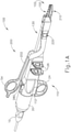
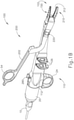
- FIGS. 1A-3 illustrate exemplary ultrasonic surgical instrument (100). At least part of instrument (100) may be constructed and operable in accordance with at least some of the teachings of U.S. Pat. No. 5,322,055 ; U.S. Pat No. 5,873,873 ; U.S. Pat. No. 5,980,510 ; U.S. Pat. No. 6,325,811 ; U.S. Pat. No. 6,773,444 ; U.S. Pat. No. 6,783,524 ; U.S. Pub. No. 2006/0079874 ; U.S. Pub. No. 2007/0191713 ; U.S. Pub. No. 2007/0282333 ; U.S. Pub. No.
- instrument (100) is operable to cut tissue and seal or weld tissue (e.g., a blood vessel, etc.) substantially simultaneously. It should also be understood that instrument (100) may have various structural and functional similarities with the HARMONIC ACE ® Ultrasonic Shears, the HARMONIC WAVE ® Ultrasonic Shears, the HARMONIC FOCUS ® Ultrasonic Shears, and/or the HARMONIC SYNERGY ® Ultrasonic Blades. Furthermore, instrument (100) may have various structural and functional similarities with the devices taught in any of the other references that are cited herein.
- Instrument (100) of the present example comprises a plug (10), a proximal casing (20), handle assembly (110), a shaft assembly (130), a blade assembly (150), a clamp arm assembly (200), and an end effector (102).
- clamp arm assembly (200) may be selectively attached to handle assembly (110) and detached from handle assembly (110).
- the ability to selectively attach and detach clamp arm assembly (200) from handle assembly (110) may provide additional benefits of reusability for either handle assembly (110) or clamp arm assembly (200).
- Handle assembly (110) comprises a body (112) including a finger grip ring (24), a button (280) on top of body (112), and a pair of buttons (126) distal to finger grip ring (24).
- Instrument (100) also includes a clamp arm assembly (200) that is pivotable toward and away from body (122).
- Clamp arm assembly (200) includes a body (202) with a thumb grip ring (54). Thumb grip ring (54) and finger grip ring (24) together provide a scissor grip type of configuration. It should be understood, however, that various other suitable configurations may be used, including but not limited to a pistol grip configuration.
- Shaft assembly (130) comprises an outer sheath (132) extending distally from body (112).
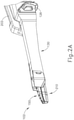
- end effector (102) comprises an ultrasonic blade (152) and a clamp pad assembly (210). End effector (102) is operable to transition between a closed position, as shown in FIG. 2A , and an open position, as show in FIG. 2B .
- Ultrasonic blade (152) extends distally from outer sheath (132). As will be described in greater detail below, ultrasonic blade (142) is a part of blade assembly (150).
- Clamp pad assembly (210) is an integral feature of clamp arm assembly (200).
- Clamp pad assembly (210) includes a clamp pad (212) facing ultrasonic blade (152).
- Clamp pad assembly (210) is pivotally coupled with outer sheath (132) via a coupling assembly (220).
- Clamp pad assembly (210) is positioned distal to coupling assembly (220); while body (202) and thumb grip ring (154) are positioned proximal to coupling assembly (220).
- clamp pad assembly (210) is pivotable toward and away from ultrasonic blade (152) based on pivoting of thumb grip ring (54) toward and away from body (112) of handle assembly (110).
- a resilient member may comprise a leaf spring, a torsion spring, and/or any other suitable kind of resilient member.
- an ultrasonic transducer assembly (30) is housed within proximal casing (20) and body (112) of handle assembly (110).
- Transducer assembly (30) is coupled with a generator (5) via a plug (10).
- Transducer assembly (30) receives electrical power from generator (5) and converts that power into ultrasonic vibrations through piezoelectric principles.
- Generator (5) may include a power source and control module that is configured to provide a power profile to transducer assembly (30) that is particularly suited for the generation of ultrasonic vibrations through transducer assembly (30).
- Generator (5) may also be configured to provide a power profile that enables end effector (102) to apply RF electrosurgical energy to tissue.
- generator (5) may comprise a GEN 300 sold by Ethicon Endo-Surgery, Inc. of Cincinnati, Ohio.
- generator (not shown) may be constructed in accordance with at least some of the teachings of U.S. Pub. No. 2011/0087212, entitled “Surgical Generator for Ultrasonic and Electrosurgical Devices," published April 14, 2011 .
- handle assembly 110
- handle assembly (110) may even include a battery or other on-board power source such that plug (10) is omitted.
- Still other suitable forms that generator (5) may take, as well as various features and operabilities that generator (5) may provide, will be apparent to those of ordinary skill in the art in view of the teachings herein.
- Ultrasonic vibrations that are generated by transducer assembly (30) are communicated along an acoustic waveguide (154).
- Waveguide (154) is mechanically and acoustically coupled with transducer assembly (30).
- Waveguide (154) extends through shaft assembly (130) to reach ultrasonic blade (152).
- Waveguide (154) is secured within shaft assembly (130) via locator pins (134, 136), which will be described in greater detail below.
- Pins (134, 136) are located at a position along the length of waveguide (154) corresponding to a node associated with resonant ultrasonic vibrations communicated through waveguide (154).
- ultrasonic blade (152) when ultrasonic blade (152) is in an activated state (i.e., vibrating ultrasonically), ultrasonic blade (152) is operable to effectively cut through and seal tissue, particularly when the tissue is being clamped between clamp pad (212) and ultrasonic blade (142).
- waveguide (154) may be configured to amplify mechanical vibrations transmitted through waveguide (154).
- waveguide (154) may include features operable to control the gain of the longitudinal vibrations along waveguide (154) and/or features to tune waveguide (154) to the resonant frequency of the system.
- the distal end of ultrasonic blade (152) is located at a position corresponding to an anti-node associated with resonant ultrasonic vibrations communicated through waveguide (154), in order to tune the acoustic assembly to a preferred resonant frequency f o when the acoustic assembly is not loaded by tissue.
- the distal end of ultrasonic blade (152) is configured to move longitudinally in the range of, for example, approximately 10 to 500 microns peak-to-peak, and in some instances in the range of about 20 to about 200 microns at a predetermined vibratory frequency f o of, for example, 55.5 kHz.
- transducer assembly (30) of the present example When transducer assembly (30) of the present example is activated, these mechanical oscillations are transmitted through the waveguide to reach ultrasonic blade (152), thereby providing oscillation of ultrasonic blade (152) at the resonant ultrasonic frequency.
- ultrasonic blade (152) when tissue is secured between ultrasonic blade (152) and clamp pad (212), the ultrasonic oscillation of ultrasonic blade (152) may simultaneously sever the tissue and denature the proteins in adjacent tissue cells, thereby providing a coagulative effect with relatively little thermal spread.
- an electrical current may also be provided through ultrasonic blade (152) and/or clamp pad (212) to also seal the tissue.
- instrument (100) is also configured to provide radiofrequency (RF) energy to a surgical site via end effector (102).
- RF radiofrequency
- an operator may rely mainly on the use of ultrasonic energy from blade (152) to sever tissue that is captured between ultrasonic blade (152) and clamp pad (212).
- the operator may further rely on the use of RF energy from end effector (102) to seal the severed tissue.
- the ultrasonic energy from blade (152) may seal tissue to some degree, such that the RF energy from end effector (102) may supplement the sealing that would already be provided from the ultrasonic energy.
- buttons (126) may activate buttons (126) to selectively activate transducer assembly (30) to thereby activate ultrasonic blade (152).
- two buttons (126) are provided.
- one button (126) is provided for activating ultrasonic blade (152) at a first power profile (e.g., a first frequency and/or first amplitude) and another button (126) is provided for activating ultrasonic blade (152) at a second power profile (e.g., a second frequency and/or second amplitude).
- one button (126) is provided for activating ultrasonic blade (152) with ultrasonic energy
- the other button (126) is provided for activating end effector (102) with RF energy.
- any other suitable number of buttons and/or otherwise selectable power levels and/or power modalities may be provided.
- a foot pedal may be provided to selectively activate transducer assembly (30).
- Buttons (126) of the present example are positioned such that an operator may readily fully operate instrument (100) with a single hand. For instance, the operator may position their thumb in thumb grip ring (54), position their ring finger in finger grip ring (124), position their middle finger about body (112), and manipulate buttons (126) using their index finger. Of course, any other suitable techniques may be used to grip and operate instrument (100); and buttons (126) may be located at any other suitable positions.
- instrument (100) may be configured in numerous other ways as will be apparent to those of ordinary skill in the art in view of the teachings herein.
- at least part of instrument (100) may be constructed and/or operable in accordance with at least some of the teachings of any of the following: U.S. Pat. No. 5,322,055 ; U.S. Pat. No. 5,873,873 ; U.S. Pat. No. 5,980,510 ; U.S. Pat. No. 6,325,811 ; U.S. Pat. No. 6,783,524 ; U.S. Pub. No. 2006/0079874 ; U.S. Pub.
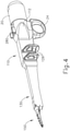
- FIG. 4 shows proximal casing (20), handle assembly (110), shaft assembly (130), and blade assembly (150) with clamp arm assembly (200) detached.
- a clamp arm assembly (200) may selectively detach from the rest of instrument (100) so that certain aspects of instrument (100) may be reusable while other features of instrument (100) are disposed of. In such case, the reusable aspects of instrument (100) will have to be cleaned and sterilized. Providing easy access to areas of instrument (100) that need to be cleaned and sterilized may ensure a thorough cleaning for the next surgical procedure.
- FIG. 5 shows a more detailed view of blade assembly (150).
- Blade assembly (150) includes ultrasonic blade (152), acoustic waveguide (154), and heat shield (170).
- heat shield (170) is capable of pivoting from an unlocked position to a locked position.
- a tube (138) projects distally from the distal end of outer sheath (132).
- Ultrasonic blade (152) is unitarily connected to acoustic waveguide (154).
- Acoustic waveguide (154) includes a proximal end (158), a distal end (156), a proximal seal (160), and a distal seal (162).
- acoustic waveguide (154) communicates ultrasonic vibrations from transducer assembly (30) to ultrasonic blade (152).
- Acoustic waveguide (154) is housed within shaft assembly (130), more specifically within tube (138) of shaft assembly (130).
- Proximal seal (160) and distal seal (162) are each located at a respective position along the length of waveguide (154) corresponding to a respective node associated with resonant ultrasonic vibrations communicated through waveguide (154).
- Proximal seal (160) and distal seal (162) are sized to abut against the interior of tube (138). Because proximal seal (160) and distal seal (162) are positioned along the length of waveguide (154) corresponding to nodes associated with resonant ultrasonic vibrations, contact between tube (138) and seals (160, 162) may not affect ultrasonic vibrations communication through waveguide (154). Interaction between distal seal (162) and tube (138) may prevent fluids from traveling proximally within tube (138) in relation to distal seal (162).
- distal seal (162) includes an upper locking feature (164) and a lower locking feature (166), which are sized to receive locator pins (134, 136).
- locking features (164, 166) are both defined by a single annular recess that extends about the circumferential perimeter of distal seal (162).
- locking features (164, 166) are formed as discrete scallops or recesses in distal seal (162).
- outer sheath (132) includes upper and lower pin holes (140, 142) that are also sized to receive locator pins (134, 136).
- Distal seal (162) is located along waveguide (154) such that upper and lower locking features (164, 166) longitudinally align with upper and lower pin holes (140, 142) respectively, when waveguide (154) is fully seated in handle assembly (110).
- tube (138) includes slots (148) that are located within outer sheath (132). Slots (148) are positioned to align with upper and lower pin holes (140, 142) of outer sheath (132). Slots (148) are also sized and located along the length of tube (130) in order to receive locator pins (134, 136).
- locator pins (134, 136) may be inserted into upper and lower pin holes (140, 142), thereby entering slots (148) of tube (138) and making contact with upper locating feature (164) and lower locating feature (166), respectively.
- Contact between upper locating feature (164) and locator pin (134), as well as contact between lower locating feature (166) and locator pin (136) impart a frictional braking force on acoustic waveguide (154). This frictional braking force simultaneously prevents acoustic waveguide (154) from rotating about its own longitudinal axis and sliding longitudinally relative to outer sheath (132).
- locator pins (134, 136) and locating features (164, 166) may help acoustic waveguide (154) remain fixed relative to outer sheath (132).
- Locating features (164, 166) and locator pins (134, 136) may also help reduce tolerance stack between ultrasonic blade (152) and clamp arm assembly (200) due to the location of locating features (164, 166) being positioned close to the distal tip of ultrasonic blade (152).
- FIGS. 5 and 8A-9 show heat shield (170) of the present example.
- heat shield (170) is capable of pivoting between an unlocked position ( FIG. 8A ) and a locked position ( FIG. 8B ).
- Heat shield (170) includes a pair of spring locks (172), a pair of coupling holes (174), an elongate body (175) that is sized to cover a portion of ultrasonic blade (152), a plurality of apertures (176) located along elongate body (175), and a distal bumper (178).
- Heat shield (170) may be metal sampled.
- Head shield (170) may also be coated with a non-stick, non-conductive coating, such as silicone, polytetrafluoroethylene (PTFE), and/or any other suitable material as will be apparent to those of ordinary skill in the art in view of the teachings herein. Because blade assembly (150) may be used multiple times, heat shield (170) may be durable in order to survive multiple uses, handling, and cleaning. By way of example only, heat shield (170) may be constructed in accordance with at least some of the teachings of U.S. Pub. No. 2015/0148833, entitled "Shielding Features for Ultrasonic Blade of a Surgical Instrument," published May 28, 2015 .
- Coupling holes (174) are spaced to align on the outside of upper pin hole (140). Coupling holes (174) are also sized to receive locator pin (134). When coupling holes (174) are aligned with pin hole (140), locator pin (134) may travel through coupling holes (174) and upper pin hole (140), thereby rotatably coupling heat shield (170) to outer sheath (132). Therefore, when assembled, heat shield (170) may rotate about the axis defined by locator pin (134), as shown in the series depicted in FIGS. 8A-8B .
- elongate body (175) When heat shield (170) is in an unlocked position, as shown in FIG. 8A , elongate body (175) may be substantially perpendicular with the longitudinal axis defined by outer sheath (132). While heat shield (170) is in the unlocked position, access is provided for cleaning portions of ultrasonic blade (152) and waveguide (154) that would otherwise be covered by heat shield (170). Additionally, tube (138) also defines an access hole (144) to provide further access to cleaning waveguide (154). When heat shield (170) is in a locked position as shown in FIG. 8B , heat shield (170) may prevent ultrasonic blade (152) from inadvertently touching non targeted tissue. Apertures (176) may allow for undesired fluid and tissue to escape the confines of heat shield (170) and ultrasonic blade (152), as to not disturb the vibration of activated ultrasonic blade (152).
- heat shield (170) includes a pair of spring locks (172).
- Spring locks (172) are sized to engage tube (138) when heat shield (170) pivots toward the locked position as shown in FIG. 8B .
- Spring locks (174) are resilient, and capable of flexing to conform to the profile of tube (138) while heat shield (170) pivots toward ultrasonic blade (152).
- Spring locks (172) are also dimensioned to enter locking slots (146) while heat shield (170) is in the locked position.
- the resilient nature of spring locks (172) allows spring locks (172) to return to their natural position once they no longer engage the profile of tube (138) by entering locking slots (146).
- heat shield (170) may be substantially fixed relative to the rest of blade assembly (150) when heat shield (170) is in a locked position. Due to the resilient nature of spring locks (172), an operator may rotate heat shield (170) away from ultrasonic blade (152) with enough force to deflect spring locks (172) out of locking slots (146), thereby decoupling spring locks (172) from tube (138). Spring locks (172) will flex outwardly to conform to the profile of tube (138) until heat shield (170) is further pivoted to a fully unlocked position.
- heat shield (170) also includes distal bumper (178).
- distal bumper (178) is formed of an electrically insulative material.
- distal bumper (178) may comprise polytetrafluoroethylene (PTFE) and/or any other suitable material(s) as will be apparent to those of ordinary skill in the art in view of the teachings herein.
- Distal bumper (178) may be pressed into place on the distal end of heat shield (170) or attached to the distal end of heat shield (170) using any other suitable features or techniques.
- ultrasonic blade (152) When ultrasonic blade (152) is in use, ultrasonic blade (152) may deflect laterally away from the longitudinal axis in response to forces provided by contact with tissue. Such deflection may urge blade (152) into contact with heat shield (170). If heat shield (170) is made of a metallic substance and instrument (100) is configured to provide RF energy to a surgical location, as described below, a short in the circuit providing RF energy to the surgical location may occur. Distal bumper (178) may thus provide a safe contact surface for ultrasonic blade (152) to contact such that if blade (152) does deflect against the metallic material in heat shield (170) and instead just contacts distal bumper (178), a short circuit of delivered RF energy may be prevented.
- heat shield (170) is made of a metallic substance and instrument (100) is configured to provide RF energy to a surgical location, as described below, a short in the circuit providing RF energy to the surgical location may occur.
- Distal bumper (178) may thus provide a safe contact surface for ultrasonic blade (152)
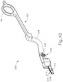
- FIGS. 10 and 11 show clamp arm assembly (200) in greater detail.
- clamp arm assembly (200) comprises a body (202), a clamp pad assembly (210), a coupling assembly (220), and a data communication assembly (240).
- Body (202) generally extends from grip (54) to provide a lever that is attachable to handle assembly (110) to support actuate end effector (102).
- Body (202) generally comprises a structural core (204) with a plastic or rubber overmolded exterior portion (206).
- structural core (204) comprises a generally electrically conducting material that is suitable to transfer RF energy through structural core (204). Core (204) thus provides a path for electrical continuity in addition to providing structural support.
- structural core (204) is configured to provide structural rigidity to clamp arm assembly (200), while exhibiting at least some elastic properties.
- exterior portion (206) electrically insulates structural core (204), thereby confining RF electrical energy within certain predetermined energy paths.
- structural core (204) includes two bracket openings (205), a single coupling opening (208), and a single data communication channel (209).
- bracket openings (205) permit at least a portion of coupling assembly (220) to pass through structural core (204) such that coupling assembly (220) is securable to structural core (204).
- coupling opening (208) is configured to permit at least a portion of handle assembly (110) to extend through structural core (204) to engage at least a portion of coupling assembly (220).
- data communication channel (209) permits at least a portion of data communication assembly (240) to pass through structural core (204) to be in communication with at least a portion of handle assembly (110).
- exterior portion (206) includes a removable cover (207) that is selectably detachable from exterior portion (206).
- Cover (207) is configured to cover and un-cover at least a portion of structural core (204) to provide operator access to coupling assembly (220) and data communication assembly (240). In some examples such access may be desirable for assembly purposes.
- Cover (207) of the present example is generally securable to exterior portion (206) by a press fit.
- cover (207) includes snaps, detents, tabs, and/or other features that may be used to secure cover (207) to exterior portion (206).
- any other suitable attachment feature may be used as will be apparent to those of ordinary skill in the art in view of the teachings herein.
- FIG. 12 shows clamp pad assembly (210) in greater detail.
- clamp pad assembly (210) comprises a clamp pad (212) and an electrode (218).
- Clamp pad (212) comprises a single generally homogenous insulating material such as polytetrafluoroethylene (PTFE), rubber, and/or other similar insulating materials.
- Clamp pad (212) comprises a gripping portion (213) and a locating portion (216).
- Gripping portion (213) is configured to grip tissue and hold such tissue in position as the tissue is being clamped between clamp pad assembly (210) and ultrasonic blade (152).
- gripping portion (213) includes a repeating pattern of ribs or teeth to enhance the grippability of gripping portion (213).
- gripping portion (213) is equipped with numerous other features to enhance grippability such as knurling, irregular surface patterns, or any other generally rough surface. In still other examples, gripping portion (213) is equipped with a merely flat surface without any particular feature to enhance grippability.
- Gripping portion (213) terminates inwardly of the outer lateral edges of clamp pad (212). This defines a shoulder (214) in clamp pad (212). As will be described in greater detail below, shoulder (214) is generally configured to maintain clamp pad (212) within body (202) via electrode (218).
- Locating portion (216) is defined in clamp pad (212) at the proximal end of clamp pad (212). Locating portion (216) extends upwardly above gripping portion (213) with an indented upper surface (217). As will be described in greater detail below, locating portion (216) is generally configured to maintain relative positioning between clamp pad (212) and blade (152) during clamping, by receiving blade (152) within upper surface (217). Accordingly, it should be understood that upper surface (217) generally corresponds to the curvature of blade (152) such that upper surface is configured to receive blade (152).
- Electrode (218) comprises a single relatively thin strip of relatively rigid electrically conducting material.
- electrode (218) comprises an electrically conductive metal such as copper, gold, steel, aluminum, silver, etc.
- electrode (218) comprises an electrically conductive non-metallic material such as conducting polymers, silicides, graphite, etc.
- the thickness of electrode (218) is generally thinner than gripping portion (213) of clamp pad (212), such that gripping portion (213) protrudes above the upper surface of electrode (218).
- electrode (218) is still generally thick enough to maintain a suitable amount of structural rigidity, as will be described in greater detail below.
- electrode (218) generally corresponds to the shape of clamp pad (212).
- electrode (218) generally defines a shape similar to an outline of clamp pad (212).
- Electrode (218) further defines an opening (219) therein. Opening (219) is configured to receive gripping portion (213) of clamp pad (212) therethrough such that electrode (218) is configured to engage with shoulder (214) of clamp pad (212).
- clamp pad (212) When clamp pad assembly (210) is assembled, clamp pad (212) is first inserted into a clamp pad receiving channel (208) defined in the distal end of body (202). Electrode (218) is then inserted over clamp pad (212), with electrode (218) seating on shoulder (214) of clamp pad (212), and with gripping portion (213) of clamp pad (212) protruding through opening (219). Electrode (218) is then resistance welded or otherwise secured to body (202). In the present example, electrode (218) is resistance welded in place to structural core (204) of body (202) at the proximal and distal ends of electrode (218). In other examples, electrode (218) is resistance welded at any other suitable location in addition to, or in lieu of, welding at the distal and proximal ends of electrode (218).
- electrode (218) is secured to body (202) by any other suitable means such as other welding processes and/or adhesive bonding, etc. It should be understood that once electrode (218) is secured to body (202), electrode (218) also couples clamp pad (212) to body (202) by engagement between electrode (218) and shoulder (214) of clamp pad (212). Accordingly, the thickness of electrode (218) is generally thick enough to provide enough rigidity to couple clamp pad (212) to body (202).
- Electrode (218) is configured to cooperate with blade (152) to provide bipolar RF electrosurgical energy to tissue that is captured between clamp pad assembly (210) and blade (152).
- electrode (218) is activated with RF energy and blade (152) provides a return path for the RF energy.
- blade (152) is capable of serving two distinct roles in the present example - one role of applying ultrasonic energy to tissue that is in contact with blade (152) and another role of cooperating with electrode (218) to provide bipolar RF energy to tissue that is captured between clamp pad assembly (210) and blade (152).
- the ultrasonic energy and RF energy are applied simultaneously.
- the ultrasonic energy and RF energy are applied in an automatically alternating fashion.
- the ultrasonic energy and RF energy are applied in a simple series (e.g., ultrasonic energy first, followed by RF energy). In some other versions, the ultrasonic energy and RF energy are selectively applied independently (e.g., with one button (126) activating ultrasonic energy and the other button activating RF energy).
- a simple series e.g., ultrasonic energy first, followed by RF energy
- the ultrasonic energy and RF energy are selectively applied independently (e.g., with one button (126) activating ultrasonic energy and the other button activating RF energy).
- electrode (218) is generally thinner than gripping portion (213) of clamp pad (212), gripping portion (213) generally protrudes upwardly from electrode (218) to prevent blade (152) from directly contacting electrode (218) when end effector (102) is in a closed configuration.
- electrode (218) is generally not configured to physically contact blade (152).
- electrical continuity for RF energy is generally achieved by passing electrical current through a patient's tissue as it is cut and/or sealed using instrument (100), and in some versions this electrical current flows between electrode (218) and blade (152).
- FIGS. 13-16 show coupling assembly (220) in greater detail.
- coupling assembly (220) comprises a coupling plate (222) and a retaining bracket (230).
- Coupling plate (222) is generally configured to receive at least a portion of handle assembly (110) to selectively couple clamp arm assembly (200) to handle assembly (110).
- the term "couple” referred to herein encompasses fixedly securing clamp arm assembly (200) to handle assembly (110) relative to at least one axis.
- clamp arm assembly (200) is couplable to handle assembly (110) such that lateral movement of clamp arm assembly (200) is restricted relative to handle assembly (110).
- coupling assembly (220) is configured to permit at least some longitudinal movement and rotational movement of clamp arm assembly (200) relative to handle assembly (110).
- Coupling plate (222) of the present example comprises a generally rectangular base (224) with a plurality of inwardly extending coupling arms (228).
- coupling plate (222) is shown as a generally unitary part, it should be understood that in other examples, coupling plate (222) comprises an assembly of a plurality of discrete parts. Regardless of whether coupling plate (222) comprises a single unitary part or a plurality of discrete parts, it should be understood that coupling plate (222) is generally comprised of a conductive metallic or conductive non-metallic material. As will be described in greater detail below, coupling plate (222) is generally configured to transfer electrical RF energy from at least a portion of handle assembly (110) to structural core (204) of body (202).
- Base (224) of coupling plate (222) defines a pair of bracket openings (225) and a single arm opening (226).
- bracket openings (225) are generally configured to receive at least a portion of retaining bracket (230) such that retaining bracket (230) and coupling plate (222) are securable to structural core (204) of body (202).
- arm opening (226) is sized to receive coupling arms (228) such that at least a portion of handle assembly (110) may extend through base (224) to engage coupling arms (228).
- Coupling arms (228) of the present example comprises two coupling arms (228), although in other examples any suitable number of coupling arms (228) is used.
- Each coupling arm (228) extends inwardly into arm opening (226) of base (224) from opposite sites of base (224). However, each arm (228) stops short of extending all the way to the adjacent arm, thereby leaving at least a portion of arm opening (226) open. As will be described in greater detail below, this portion of arm opening (226) is configured to permit at least a portion of handle assembly (110) to extend through base (224) and past arms (228) such that at least a portion of handle assembly (110) engages arms (228).
- Each coupling arm (228) is laterally offset from base (224).
- this structure is formed by stamping a bend in base (224) and each coupling arm (228) to position each arm (228) laterally away from base (224).
- this feature of arms (228) is configured to suitably align handle assembly (110) when at least a portion of handle assembly (110) engages arms (228).
- each coupling arm (228) of the present example is configured to be resilient As will also be described in greater detail below, this resilient feature of arms (228) provides spring like characteristics to arms (228) to further promote alignment between handle assembly (110) and clamp arm assembly (200) along a transverse plane.
- Retaining bracket (230) comprises a base portion (232) and a pair of retaining studs (238).
- Base portion (232) comprises a plate having a generally triangular shape, although any other suitable shape may be used in other examples.
- Base portion (232) further includes a plurality of data communication openings (233), and a single coupling opening (234).
- Base portion (232) of the present example defines three discrete data communication openings (233), although in other examples any other suitable number of data communication openings (233) may be defined in base portion (232).
- data communication openings (233) are configured to permit at least a portion of data communication assembly (240) to extend through retaining bracket (230) to communicate with handle assembly (110).
- Coupling opening (234) is centrally disposed within base portion (232). As will be described in greater detail below, coupling opening (234) is sized to permit at least a portion of handle assembly (110) to pass through base portion (232) to engage coupling plate (222). As will also be described in greater detail below, coupling opening (234) is further configured to align with a corresponding opening (208) in structural core (204) of body (202) to further permit at least a portion of handle assembly (110) to pass thorough base portion (232) to engage coupling plate (222).
- Base portion (232) further includes a plurality of alignment features (235, 236).
- Each alignment feature (235, 236) comprises a laterally extending cylindrical protrusion.
- Alignment features (235, 236) are generally configured to locate base portion (232) relative to clamp arm assembly (200).
- alignment features (235, 236) comprise a pair of data communication alignment features (235) that locate data communication assembly (240) relative to base portion (232).
- alignment features (235, 236) further comprise a single base alignment feature (236) that locates base portion (232) relative to structural core (204) of body (202).
- each alignment feature (235, 236) is configured to engage a corresponding bore or opening (not shown) of data communication assembly (240) and structural core (204), respectively.
- Retaining studs (238) comprise a generally cylindrical shape and extend laterally from base portion (232). Each retaining stud (238) comprises a retaining feature (239) disposed on the lateral end of each retaining stud (238). Each retaining feature (239) is formed as a head that is generally cylindrical in shape and includes a diameter that is greater than the diameter of each retaining stud (238). As will be understood, retaining features (239) are generally configured to secure retaining bracket (230) to clamp arm assembly (200) and further secure base portion (232) to clamp arm assembly (200).
- retaining studs (238) extend through bracket openings (205) of structural core (204) and through bracket openings (225) of coupling plate (222).
- exterior portion (206) of body (202) is also overmolded into bracket openings (205) of structural core (204) to surround retaining studs (238), although such a configuration is merely optional.
- Coupling plate (222) is fixedly secured to retaining bracket (230) and correspondingly to structural core (204) by retaining studs (238).
- retaining studs (238) extend through bracket openings (205) of structural core (204) and through bracket openings (225) of coupling plate (222).
- exterior portion (206) of body (202) is overmolded into a shape corresponding to the geometry of retaining studs (238). The positioning of coupling plate (222) is then maintained relative to body (202) and retaining bracket (230) by a compression fit between exterior portion (206) of body (202) and retaining studs (238). While FIG.
- FIG. 15 shows one merely exemplary configuration for securing coupling plate (222) and retaining bracket (230) to structural core (204), it should be understood that in other example numerous alternative configurations are used. For instance, in some examples retaining studs (238) extend through bracket openings (205, 225) without exterior portion (206) and connect directly to coupling plate (222) via screws, washers, bolts and/or other attachment features. Of course other suitable configurations for securing coupling plate (222) and retaining bracket (230) to structural core (204) will be apparent to those of ordinary skill in the art in view of the teachings herein.
- coupling plate (222) is in direct physical contact with structural core (204) of body (202). Because both structural core (204) and coupling plate (222) are both electrical conductors, it should be understood that coupling plate (222) is in electrical communication with structural core (204). As will be described in greater detail below, this permits electrical RF energy to be communicated from at least a portion of handle assembly (110) to electrode (218) via coupling plate (222) and structural core (204).
- FIGS. 13-14 show data communication assembly (240) in more detail.
- data communication assembly (240) comprises a plurality of electrical connectors (242), a printed circuit board (246), and an electrical circuit (248).
- Data communication assembly (240) of the present example comprises three electrical connectors (242), although in other examples any suitable number may be used.
- Each electrical connector (242) of the present example is generally configured as a pogo pin-style connector.
- each electrical connector (242) comprises a barrel (243) and a ball (244) protruding from each barrel (243).
- connectors (242) may take any other suitable form.
- Barrel (243) is attached to printed circuit board (246) to provide electrical communication between electrical connector (242) and printed circuit board (246).
- each barrel (243) also includes one or more resilient features such as a spring located within each barrel (243).
- Each ball (244) protrudes from each barrel (243) and is held in position by the one or more resilient features.
- Each ball (244) is configured to act as an electrical contact to communicate electrical current through barrel (243) to printed circuit board (246).
- each ball (244) is configured to travel through a predetermined range of motion to permit some movement of ball (244) while still maintaining electrical continuity with a corresponding electrical contact.
- each electrical connector (242) is generally configured to pass through structural core (204) of body (202) to provide data communication between handle assembly (110) and clamp arm assembly (200).
- Electrical circuit (248) communicates electrical current from electrical connectors (242) to electrical circuit (248).
- electrical circuit (248) is in electrical communication with electrical connectors (242) via printed circuit board (246) to send and/or receive data.
- electrical circuit (248) includes at least a non-volatile memory chip, as well as other operational components such as integrated circuits.
- electrical circuit (248) is generally configured to provide various types of data regarding clamp arm assembly (200) to generator (5) via handle assembly (110).
- each ball (244) of each electrical connector (242) is resiliently biased to protrude laterally at least partially through body (202) from a side opposite of coupling plate (222).
- the particular amount of protrusion of balls (244) in the present example is approximately equivalent to the predetermined range of motion of each ball (244), although the amount of protrusion is varied in other examples.
- balls (244) generally protrude from body (202) to provide electrical continuity between data communication assembly (240) and handle assembly (110).
- FIG. 16 shows another view of balls (244) protruding through body (202).
- the exterior of body (202) is equipped with a seal (249) covering retaining bracket (230).
- Seal (249) of the present example is overmolded onto body (202), although in other examples numerous other means of attachment are used to secure seal (249) to body (202).
- Seal (249) is configured to provide a fluid seal between the exterior of clamp arm assembly (200) and data communication assembly (240). This prevents various fluids encountered during a surgical procedure that may harm components of data communication assembly (240) (e.g., electrical circuit (248)) from otherwise entering data commutation assembly (240).
- FIGS. 17-18 show a coupling assembly (250) of handle assembly (110) that is generally configured to selectively couple with clamp arm assembly (200).
- coupling assembly (250) includes an attachment member (252) and a plurality of electrical contacts (266).
- Attachment member (252) comprises a base (253), and an attachment portion (254).
- Base (253) is generally cylindrical in shape and extends laterally from the interior of handle assembly (110). At the lateral-most end of base (253) the outer diameter of base (253) narrows to define a generally circular channel (256) between base and attachment portion (254).
- Attachment portion (254) of the present example is of unitary construction with base (253) such that base (253) and attachment portion (254) are formed of a single component.
- attachment portion (254) is a discrete component that is secured or otherwise fastened to base (253).
- Attachment portion (254) is disposed laterally of base (253), adjacent to channel (256).
- Attachment portion (254) is generally disc-shaped with two flat portions (258) on opposing sides of attachment portion (254). As will be described in greater detail below, flat portions (258) are generally configured to selectively engage coupling plate (222) of clamp arm assembly (200).
- attachment portion (254) further includes a first translation feature (260) and a second translation feature (262).
- Translation features (260, 262) extend transversely along the exterior of attachment portion (254).
- a corresponding first translation feature (261) and second translation feature (263) are similarly associated with base (253) such that base (253) also includes translation features (261, 263) that extend transversely along the exterior of base (253).
- translation features (260, 261, 262, 263) are configured to translate clamp arm assembly (200) relative to handle assembly (110) as clamp arm assembly (200) is pivoted relative to handle assembly (110), through interaction with corresponding protrusions (201) (shown in FIG. 16 ) in body (206) of clamp arm assembly (200).
- FIG. 18 also shows electrical contacts (266).
- coupling assembly (250) of handle assembly (110) includes three discrete electrical contacts (266).
- electrical contacts (266) are configured to correspond to electrical connectors (242) of data communication assembly (240) such that electrical current may be communicated between electrical contacts (266) and electrical connectors (242).
- electrical contacts (266) are spaced a predetermined angular distance from each other along an arc.
- Each electrical contact (266) is generally positioned flush with the exterior of handle assembly (110).
- each electrical contact (266) is positioned to be recessed slightly below the outer surface of handle assembly (110). Regardless of the particular positioning of electrical contacts (266), it should be understood that electrical contacts (266) are generally in communication with the interior of handle assembly (110) to communicate electrical signals from clamp arm assembly (200) to generator (5).
- FIGS. 19A through 21 show an exemplary procedure for coupling clamp arm assembly (200) to handle assembly (110).
- a detached clamp arm assembly (200) is initially positioned relative to handle assembly (110) such that the longitudinal axis of clamp arm assembly (200) is positioned at 90° relative to the longitudinal axis of handle assembly (110).
- Opening (208) is coaxially aligned with attachment member (252); and clamp arm assembly (200) is spaced laterally from handle assembly (110).
- clamp arm assembly (200) is positioned as shown in FIG. 19A , an operator may begin coupling clamp arm assembly (200) to handle assembly (110).
- clamp arm assembly (200) is moved laterally by an operator along the axis shared by opening (208) and attachment member (252) to bring clamp arm assembly (200) into contact with handle assembly (110).
- attachment member (252) of handle assembly (110) is guided through opening (208) of clamp arm assembly (200) to the position shown in FIG. 20 .
- attachment member (252) of handle assembly (110) passes through body (202) of clamp arm assembly (200).
- flat portions (258) of attachment portion (254) are aligned with coupling arms (228) of coupling plate (222) such that attachment portion (254) is aligned to pass through arm opening (226) of coupling plate (222).
- attachment portion (254) is correspondingly disposed laterally of coupling arms (228) such that channel (256) of attachment portion (254) is laterally aligned with coupling arms (228).
- attachment member (252) is suitably positioned relative to clamp arm assembly (200) as shown in FIG.20 , an operator may rotate or pivot clamp arm assembly (200) relative to handle assembly (110), about the axis shared by opening (208) and attachment member (252), to selectively couple clamp arm assembly (200) to handle assembly (110).
- coupling arms (228) correspondingly rotate relative to attachment member (252) such that flat portions (258) of attachment portion (254) move out of alignment with coupling arms (228).
- attachment portion (254) engages coupling arms (228) to thereby couple clamp arm assembly (200) to handle assembly (110).
- attachment portion (254) includes chamfers, fillets, and/or other features that are configured to promote engagement between attachment portion (254) and coupling arms (228).
- instrument (100) may be used by an operator to cut and/or seal tissue as described below. It should be understood that at any time during use, an operator may decouple clamp arm assembly (200) from handle assembly (110) by returning clamp arm assembly (200) to the position relative to handle assembly (110) shown in FIG. 19B (e.g., oriented perpendicularly relative to handle assembly (110)). While clamp arm assembly (200) is coupled to handle assembly (110) at angular positions other than that shown in FIGS. 19B and 20 , lateral movement of clamp arm assembly (200) relative to handle assembly (110) is generally restrained; while rotational movement and at least some translation is permitted.
- clamp arm assembly (200) Although lateral movement of clamp arm assembly (200) is generally restrained, it should be understood that at least some lateral movement may be permitted by the resilient nature of coupling arms (228). Of course, in some examples the particular amount of such movement is varied by providing clamp arms (228) of more or less resiliency. While gross lateral movement of clamp arm assembly (200) is generally undesirable, some minimal amount of lateral movement may be desirable in some examples to account for tolerance variations in instrument.
- FIGS. 22A-C show an exemplary mode of operation between data communication assembly (240) of clamp arm assembly (200) and electrical contacts (266) of handle assembly (110).
- FIG. 22A corresponds to the position of data communication assembly (240) relative to electrical contacts (266) when end effector (102) is in the closed configuration (e.g., as shown in FIGS. 1A and 2A ).
- clamp arm assembly (200) is pivoted such that each electrical connector (242) of data communication assembly (240) is in electrical communication with the distal most portion of each corresponding electrical contact (266) of handle assembly (110). Accordingly, when end effector (102) is in the closed configuration, there is electrical continuity between electrical connectors (242) of clamp arm assembly (200) and electrical contacts (266) of handle assembly (110).
- FIG. 22B corresponds to the position of data communication assembly (240) relative to electrical contacts (266) when end effector (102) is on the open configuration (e.g., as shown in FIGS. 1B and 2B ).
- clamp arm assembly (200) is pivoted such that each electrical connector (242) of data communication assembly (240) is in electrical communication with the proximal most position of each corresponding electrical contact (266) of handle assembly (110). Accordingly, when end effector (102) is in the open configuration (and pivotal states between the open configuration and closed configuration), electrical continuity remains between electrical connectors (242) of clamp arm assembly (200) and electrical contacts (266) of handle assembly (110).
- end effector (102) corresponds to the maximum recommended end effector (102) opening during a surgical procedure. Although this is described herein as a maximum recommended configuration, it should be understood that end effector (102) may be optionally opened a greater distance (particularly for decoupling clamp arm assembly (200) from handle assembly (110)). As will be described in greater detail below, in some examples end effector (102) or other components of instrument (10) include detents or other features suitable to alert an operator to being in the properly open configuration.
- FIG. 22C corresponds to the position of data communication assembly (240) relative to electrical contacts (266) when end effector (102) is in a fault configuration - where clamp arm assembly (200) is opened beyond the proper open configuration described above.
- clamp arm assembly (200) is pivoted such that each electrical connector (242) of data communication assembly (240) is in an open circuit state relative to each corresponding electrical contact (266) of handle assembly (110).
- electrical continuity between electrical connectors (242) of clamp arm assembly (200) and electrical contacts (266) of handle assembly (110) is eliminated.
- this condition signals to generator (5) that end effector (102) has been opened into an undesirable range.
- a condition may be used in some examples to indicate an error condition, such as clamp arm assembly (200) not being properly coupled to handle assembly (110).
- a condition may be used to indicate removal of clamp arm assembly (200) to indicate to generator (5) that clamp arm assembly (200) has been used for a surgical procedure.
- Such an event may then be stored in non-volatile memory of electrical circuit (248) to deter reuse of clamp arm assembly (200) with other instruments (10) or the same instrument (10).
- any other suitable use of such a condition may be provided as will be apparent to those of ordinary skill in the art in view of the teachings herein.
- FIG. 23 shows an exemplary current path for coupling assembly (220).
- structural core (204) of body (202) extends through body (202) to the distal end of body (202).
- structural core (204) is coupled to electrode (218) by resistance welding as described above.
- structural core (204) is configured to be in electrical communication with electrode (218).
- coupling plate (222) of coupling assembly (220) is secured to body (202) to be in electrical communication with structural core (204).
- coupling plate (222) is configured to be in electrical communication with electrode (218) via structural core (204).
- attachment member (252) of coupling assembly (250) is also in electrical communication with coupling plate (222).
- the mechanical coupling between attachment member (252) and coupling plate (222) also provides an electrical coupling between clamp arm assembly (200) and handle assembly (110). Because coupling plate (222) is configured to be in electrical communication with electrode (218), the electrical coupling between attachment member (252) and coupling plate (222) is configured to permit electrical communication between handle assembly (110) and electrode (218).
- Attachment member (252) of handle assembly (110) is in electrical communication with generator (5) via contact (270).
- contact (270) extends longitudinally through handle assembly (110) and is configured to be electrically coupled to attachment member (252).
- contact (270) comprises a printed circuit board with one or more electrical traces disposed therein. In such examples, at least one trace is coupled to attachment member (252) (e.g., soldered) to be in electrical communication with attachment member (252).
- contact (270) is simply configured as a wire.
- contact (270) also includes one or more discrete conductors that are in electrical communication with electrical contacts (266) of handle assembly (110). Such conductors similarly extend through the interior of handle assembly (110) and provide electrical communication between electrical contacts (266) and generator (5). Electrical communication between contact (270) and electrical contacts (266) is generally configured to permit data communication assembly (240) to communicate data to generator (5).
- clamp pad assembly (210) may comprise one or more sensors that are operable to sense characteristics of clamp pad assembly (210), and/or tissue; and data from such one or more sensors may be communicated to generator (5) via contact (270) and electrical contacts (266).
- clamp pad assembly (210) may comprise an EEPROM in or similar device in communication with contacts (266) that enables generator (5) to determine that clamp arm assembly (200) is only used once (e.g., generator (5) may disable functionality and/or provide an error message when generator (5) determines that clamp arm assembly (200) has been previously used, based on data from an EEPROM communicated via contact (270) and electrical contacts (266)).
- at least one electrical contact (266) is configured to form a bridge circuit with the electrical communication path of electrode (218), structural core (204), coupling plate (222), and attachment member (252). In such examples, this circuit may be desirable because such a bridge circuit may permit generator (5) to detect when there is suitable electrical continuity to complete an RF energy circuit path before tissue is present to complete the RF energy circuit between blade (152) and electrode (218).
- FIG. 24 shows an exemplary alternative coupling assembly (320) that may be readily incorporated into clamp arm assembly (200) of instrument (10).
- coupling assembly (320) is substantially the same as coupling assembly (220) described above.
- coupling assembly (320) comprises a coupling plate (322) and a retaining bracket (330).
- Retaining bracket (330) is substantially the same as retraining bracket (230) described above such that the particular details of retaining bracket will not be repeated herein.
- Coupling plate (322), like coupling plate (222), is generally configured to receive at least a portion of handle assembly (110) to selectively couple clamp arm assembly (200) to handle assembly (110).
- Coupling plate (322) of the present example comprises a generally rectangular base (324). Like coupling plate (222), coupling plate (322) is generally comprised of a conductive metallic or conductive non-metallic material.
- Base (324) of coupling plate (322) defines a pair of bracket openings (325) and a single spring opening (326).
- bracket openings (325) are generally configured to receive at least a portion of retaining bracket (330) such that retaining bracket (330) and coupling plate (322) are securable to structural core (204) of body (202).
- spring opening (326) is sized such that at least a portion of handle assembly (110) may extend through base (224).
- spring opening (326) is not sized for any structure similar to coupling arms (228) because coupling arms (228) are omitted in the present example. Instead, as will be described in greater detail below, the functional features of coupling arms (228) are replaced with a spring member (328).
- Spring member (328) comprises a cylindrical wire with resilient and electrically conductive characteristics. As will be described in greater detail below, spring member (328) is generally configured to be resiliently biased toward the configuration shown in FIG. 24 , but also be elastically deformable in response to coupling with handle assembly (110).
- some merely exemplary materials for cylindrical wire include metals such as steel, aluminum, copper, gold, or aluminum.
- spring member (328) comprises a non-metallic conductor having resilient characteristics. Regardless of materials, spring member (328) is bent into a configuration resembling coupling arms (228) described above. However, spring member (328) also forms at least one coil for added resilient characteristics.
- base (324) includes protrusions or other features to maintain spring member (328) in the position shown in FIG. 24 .
- the present example also includes an alternative coupling assembly (350) that is associated with handle assembly (110).
- coupling assembly (350) of the present example is substantially the same as coupling assembly (250) described above unless otherwise specifically noted herein.
- coupling assembly (350) of the present example includes an attachment member (352) and a plurality of electrical contacts (not shown).
- the electrical contacts are substantially the same as electrical contacts (266) described above such that the electrical contacts will not be described in further detail herein.
- attachment member (352) of the present example comprises a base (not shown), and an attachment portion (354).
- Base (353) is configured substantially the same as base (253) described above such that the particular details of base (253) will not be described in further detail herein.
- the outer diameter of base narrows to define a generally circular channel (356) between base and attachment portion (354).
- channel (356) is configured to receive spring member (328) to couple clamp arm assembly (200) to handle assembly (110).
- Attachment portion (354) of the present example is of unitary construction with base (353) such that base (353) and attachment portion (354) are formed of a single component Attachment portion (354) is disposed laterally of base (353), adjacent to channel (356).
- Attachment portion (354) is generally cylindrical in shape. However, unlike attachment portion (254), described above, attachment portion (354) omits structures similar to flat portions (258). Instead, attachment portion (354) is generally circular in shape with an annularly chamfered lateral end (358). As will be described in greater detail below, chamfered lateral end (358) is generally configured to promote outward deformation of spring member (328) as clamp arm assembly (200) is inserted onto handle assembly (110).
- FIGS. 25A-25C show an exemplary operation for attaching clamp arm assembly (200) to handle assembly (110) when equipped with respective coupling assemblies (320, 350).
- the procedure for coupling is generally substantially similar to the procedure described above with respect to coupling assemblies (220, 250), except where otherwise specifically noted herein.
- clamp arm assembly (200) is initially oriented perpendicularly relative to handle assembly (110) and laterally offset from handle assembly (110).
- coupling assembly (320) may be oriented at numerous other alternative angular positions relative to handle assembly (110) at the stage shown in FIG. 25A .
- attachment portion (354) is generally cylindrical in shape and spring member (328) is generally deformable, spring member (328) may engage attachment portion (354) at any suitable angular position about attachment portion (354) (provided clamp arm assembly (200) and handle assembly (110) remain laterally aligned along the longitudinal axis of attachment portion (354)).
- clamp arm assembly (200) To couple clamp arm assembly (200) to handle assembly (110), an operator merely translates clamp arm assembly (200) transversely toward handle assembly (110), along the longitudinal axis of attachment portion (354), as shown in FIG. 25B .
- This translation causes chamfered lateral end (358) of attachment portion (354) to engage spring member (328) of coupling assembly (320).
- Engagement between chamfered lateral end (358) and spring member (328) as clamp arm assembly (200) is translated as shown in FIG. 25B causes spring member (328) to deform outwardly. Spring member (328) continues to deform outwardly until spring member (328) continues past attachment portion (354).
- spring member (328) Once spring member (328) has been moved past attachment portion (354), spring member (328) enters channel (356) and elastically returns to its initial position as shown in FIG. 25C . Once spring member (328) returns to its initial position, clamp arm assembly (200) is coupled to handle assembly (110) and instrument (10) may be used by an operator as described herein. If an operator should desire to decouple clamp arm assembly (200) from handle assembly (110), clamp arm assembly (200) is merely pulled transversely from handle assembly (110) with sufficient force to deform spring member (328) outwardly, thereby removing spring member (328) from channel (356).
- FIGS. 26A-31 show an alternative clamp arm assembly (400) connecting to an alternative shaft assembly (530) and blade assembly (550).
- clamp arm assembly (400), shaft assembly (530), and blade assembly (550) are substantially the same as clamp arm assembly (200), shaft assembly (130), and blade assembly (150) as mentioned above, except for the differences described below. Therefore, is should be understood that clamp arm assembly (400), shaft assembly (530) and blade assembly (550) may substitute clamp assembly (200), shaft assembly (130), and blade assembly (150) in instrument (100).
- Shaft assembly (530) includes an outer sheath (532) and a t-nut (502) extending laterally from outer sheath (532).
- T-nut (502) is dimensioned to receive clamp arm assembly (400), and clamp arm assembly (400) is configured to rotate about axis defined by t-nut (502), as will be described in greater detail below.
- Clamp arm assembly (400) includes a body (402), a coupling assembly (420), and a clamp pad assembly (410).
- Body (402) and clamp pad assembly (410) are substantially similar to body (202) and clamp pad assembly (210) described above.
- Coupling assembly (420) is substantially similar to coupling assembly (220) described above except for the differences described below.
- Coupling assembly (420) includes a pivot base (430), a pivot lock (440), and a pivot cap (460).
- Pivot base (430) includes a recess (432) for receiving pivot lock (440) and pivot cap (460), a pair of protrusions (434), and an elongate opening (436) for receiving t-nut (502).
- Pivot lock (440) includes a pair of coupling openings (442), a resilient lock (444) and an elongate opening (446) for receiving t-nut (502).
- Pivot cap (460) includes an unlocking feature (464) and an elongate opening (466) for receiving t-nut (502).
- coupling assembly (420) has three individual pieces of pivot base (430), pivot lock (440), and pivot cap (460), it is contemplated that coupling assembly (420) could instead be formed by just one unitary piece, two pieces, four pieces, or more.
- body (402) of clamp arm assembly (400) is initially oriented perpendicular to outer sheath (532) and laterally offset from outer sheath (532), so that t-nut (502) is aligned with complementary openings (436, 446, 466).
- pivot base (430) is then translated transversely toward outer sheath (532) so that t-nut (502) is inserted into complementary opening (436).
- pivot lock (440) is then translated transversely toward pivot base (430) so that protrusions (434) and couplings openings (442) mate.
- pivot lock (440) is secured within the confines of recess (432) while t-nut (502) in also inserted into complementary opening (446). Then, as shown in FIG. 26D , pivot cap (460) is translated transversely into position on top of both pivot base (430) and pivot lock (440) such that complementary recess (460) aligns with t-nut (502). Pivot cap (460) may be secured to pivot base (430) through a snap fit or any other suitable means known in the art in view of the teachings herein.
- pivot base (430), pivot lock (440), and pivot cap (460) are each installed relative to shaft assembly (530) separately, it should be understood that pivot lock (440) and pivot cap (460) may be pre-installed on pivot base (430) prior to assembling coupling assembly (420) with shaft assembly (530).
- pivot lock (440) and pivot cap (460) may be pre-installed on pivot base (430) prior to assembling coupling assembly (420) with shaft assembly (530).
- the series shown in FIGS. 26A-26C should not be viewed as an exhaustive representation of how clamp arm assembly (400) may be secured to outer sheath (532). Instead, the series shown in FIGS. 26A-26C may be viewed as simply showing the relationships between the components of coupling assembly (420).
- Resilient lock (444) extends outwardly from the rest of pivot lock (440), toward pivot cap (460). As shown in FIGS. 27A-27B , resilient lock (444), in its natural position, may engage t-nut (502) if clamp arm assembly (400) is rotated to a predetermined locking angle. T-nut (502) is rotationally fixed about its own longitudinal axis relative to outer sheath (532). Therefore, interaction between t-nut (502) and resilient lock (444) limits the rotation of clamp arm assembly (400) when resilient lock (444) is in its natural position. Resilient lock (444) thus restricts the degree to which clamp pad assembly (410) may be pivoted away from blade assembly (550).
- Pivot cap (460) includes unlocking feature (464).
- Unlocking feature (464) is also resilient, but is biased toward a position that is aligned with the rest of pivot cap (460) as shown in FIG. 28A .
- an operator may press unlocking feature (464) toward pivot lock (440), thereby forcing unlocking feature (464) to engage resilient lock (444).
- resilient lock (444) will then flex to be aligned with the rest of pivot lock (440).
- resilient lock (444) is no longer positioned to engage t-nut (502), and the operator may thus rotate clamp arm assembly (400) past the predetermined locking angle. As shown in FIG.
- clamp arm assembly (400) may be rotated to the position shown in FIG. 27D , where t-nut (502) is aligned with complementary openings (436, 446, 466). Clamp arm assembly (400) may then be removed from shaft assembly (530) by pulling clamp arm assembly (400) laterally away from shaft assembly (530) along the longitudinal axis fo t-nut (502).
- clamp arm assembly (400) may include a resilient, cantilevered detent (412) slightly protruding from a recess (414). Cantilevered detent (412) may be positioned to align within an arcuate slot (534) formed laterally in outer sheath (532) as shown in FIGS. 30-31 . As shown in FIG.
- cantilevered detent (412) is resiliently biased to slightly protrude from an interior face (404) of clamp arm assembly (400) such that the end of cantilevered detent (412) rests within slot (534).
- clamp arm assembly (400) is pivoted past a predetermined angle, the end of cantilevered detent (412) makes contact with the end of slot (534), thereby providing tactile feedback to an operator (e.g., by providing some degree of resistance to further pivotal movement of clamp arm assembly (400) relative to shaft assembly (530)), indicating that clamp arm assembly (400) has been rotated to the predetermined angle.
- recess (414) allows cantilevered detent (412) to deflect fully into recess (414) to enable the operator to continue pivoting clamp arm assembly (400) relative to shaft assembly (530) beyond the predetermined angle, though the operator must overcome the additional force required to deflect detent (412) fully into recess (414).
- FIGS. 32-35 show an exemplary use of instrument (10) during a surgical procedure. It should be understood that prior to such a procedure, an operator may couple clamp arm assembly (200) to handle assembly (110) using the procedures and methods described above. As can be seen in FIG. 32 , an operator may clamp end effector (102) by pivoting clamp arm assembly (200) from the position shown in FIG. 1B to the position shown in FIG. 32 , with tissue captured between clamp pad assembly (210) and blade (152). End effector (102) may then cut and/or seal tissue using a combination of ultrasonic and RF energy, respectively.
- button (280) is disposed near the proximal end of handle assembly (110).
- button (280) is disposed in a position that is adjacent to grip (54).
- Button (280) is configured to be activated after a predetermined amount of clamping force has been applied by an operator to clamp arm assembly (200). For instance, as shown in FIG. 32 , when a suitable amount of clamping force is applied, clamp arm assembly (200) will deflect slightly. Such a deflection results in the underside of grip (54) contacting button (280) to actuate button (280).
- button (280) When button (280) is actuated, a signal is sent to generator (5) that a suitable amount of clamping force has been applied.
- the signal from button (280) to generator (5) causes generator (5) to either initiate a sealing algorithm (if one of buttons (126) is already being actuated) or enable initiation of a sealing algorithm (which would thereafter be initiated in response to actuation of a button (126)).
- actuation of button (280) lets the user know that clamp arm assembly (200) is fully compressed and the appropriate force is on the tissue to achieve a proper seal during execution of a sealing algorithm. In some procedures a desired quality for a seal is best achieved with there is sufficient heat and pressure applied to the tissue and/or vessel.
- buttons (126) are actuated to seal the tissue
- a user may understand that the appropriate force on the tissue for proper sealing was not obtained when the RF energy for sealing was applied to the tissue.
- actuation of button (280) can be monitored through the sealing action to understand if the appropriate amount of force was maintained on the tissue throughout the application of the RF energy for sealing the tissue.
- generator (5) may react to a combination of button (280) being actuated and one of buttons (126) being actuated. It should be understood that the following examples are merely illustrative.
- button (126) and button (280) are both actuated.
- the actuation of button (126) and button (280) initiates a seal only mode where RF energy is provided and no or lower harmonic energy is provided.
- This condition indicates to generator (5) the presence of all conditions necessary to suitably seal tissue.
- generator (5) will initiate a sealing algorithm to apply RF energy, with or without ultrasonic energy, to any tissue captured between clamp pad assembly (210) and blade (152).
- only ultrasonic energy may be used for sealing, while in other examples only RF energy may be used for sealing.
- an end tone or seal complete tone, or other auditory or visual indicator may be provided by generator (5).
- the completion of the sealing algorithm may be dictated when a threshold of impedance is reached.
- the end tone may be provided in the present example, the occurrence of the end tone does not end the application of RF energy. On the contrary, in the present example RF energy continues after the end tone so long as button (126) and button (280) continue to be actuated.
- a timer may also be provided where if the RF sealing takes longer than a predetermined amount of time then an error tone sounds to tell the operator to release and re-grasp the tissue and/or vessel.
- button (280) is not activated, but button (126) is activated.
- this action initiates a spot coagulation mode where RF energy is provided at a normal or higher voltage and no or lower harmonic energy is provided.
- generator (5) initiates a coagulation algorithm to apply RF energy, with or without ultrasonic energy, to tissue that is captured between clamp pad assembly (210) and blade (152).
- no end tone or other indication will be provided to the operator.
- no error tone will be provided to the operator.
- the coagulation algorithm will continue to run for as long as button (126) is activated so the operator can perform spot coagulation with no timeout or interruptions in RF energy application. In this manner, the clamp assembly (200) can be slightly open or spread apart to aid in spot or side coagulation.
- buttons (280) and (126) are activated, generator (5) activates a touch up algorithm.
- the touch up algorithm is activated, a higher voltage is applied to the RF circuit to ablate any excess tissue that may be captured between clamp pad assembly (210) and blade (152).
- generator (5) In a fourth exemplary scenario, if button (280) is not activated while button (126) is activated, generator (5) applies no voltage to the RF circuit Instead, generator (5) simply supplies an operator with an error tone, or other auditory or visual indicator to indicate an error.
- button (126) and button (280) are both actuated and generator (5) initiates a sealing algorithm where RF energy is provided and an increase in harmonic energy is provided for sealing.
- generator (5) initiates a sealing algorithm where RF energy is provided and an increase in harmonic energy is provided for sealing.
- depressing button (126) alone may provide RF energy and/or no or low harmonic energy, when depressing or actuating both button (126) and button (280), the increased harmonic energy is provided for sealing.
- an end tone or seal complete tone, or other auditory or visual indicator may be provided by generator (5).
- the completion of the sealing algorithm may be dictated when a threshold of impedance is reached.
- end tone may be provided in the present example, RF energy and increased harmonic energy continues after the end tone so long as button (126) and button (280) continue to be actuated.
- a timer may also be provided where if the sealing takes longer than a predetermined amount of time then an error tone sounds to tell the operator to release and re-grasp the tissue and/or vessel.
- actuating both buttons (126, 280) causes an increase in the harmonic energy, after the end tone occurs, one or more of the RF energy and harmonic energy may cease until a release and re-grasping step is performed by the operator.
- button (280) is omitted In examples where button (280) is omitted, it may still be desirable to sense the force applied to tissue through end effector (102) because seal quality may be generally related to the force applied to tissue via end effector (102).
- tissue impendence may be measured by generator (5) to determine whether adequate force is being applied to tissue.
- generator (5) is configured to measure the impedance of tissue captured between electrode (218) and blade (152) by applying a test voltage through electrode (218) and blade (152). When generator (5) measures harmonic impedance within a certain predetermined range, generator (5) will determine that a suitable amount of force is being applied to tissue captured between clamp pad assembly (210) and blade (152) and thereby positively activate a force indicator.
- generator (5) may be responsive to measurements of harmonic impedance by similarly activating various algorithms. For instance, in configurations where button (280) is omitted, positive activation of the force indicator can be equated to activation of button (280) as described in the above scenarios where button (280) is present, and generator (5) configured to respond in the same manner described above. For instance, in a first exemplary scenario when button (126) is activated along with a force indicator being activated (e.g., where harmonic impendence indicates that blade (152) is under a clamping load, thereby indicating a clamping force by clamp pad assembly (210)), generator (5) responds by activating the sealing algorithm as described above.
- a force indicator e.g., where harmonic impendence indicates that blade (152) is under a clamping load, thereby indicating a clamping force by clamp pad assembly (210)
- generator (5) responds by activating the sealing algorithm as described above.
- generator (5) may still initiate the coagulation algorithm as described above.
- generator (5) activates a touch up algorithm.
- the touch up algorithm When the touch up algorithm is activated, a higher voltage is applied to the RF circuit to ablate any excess tissue that may be captured between clamp pad assembly (210) and blade (152).
- generator (5) applies no voltage to the RF circuit. Instead, generator (5) simply supplies an operator with an error tone or other auditory or visual indicator to indicate an error.
- button (126) and the force indicator are both activated and generator (5) initiates a sealing algorithm where RF energy is provided and an increase in harmonic energy is provided for sealing.
- generator (5) initiates a sealing algorithm where RF energy is provided and an increase in harmonic energy is provided for sealing.
- depressing button (126) alone may provide RF energy and/or no or low harmonic energy, when depressing or actuating button (126) when the force indicator is also activated, the increased harmonic energy is provided for sealing.
- an end tone or seal complete tone, or other auditory or visual indicator may be provided by generator (5). The completion of the sealing algorithm may be dictated when a threshold of impedance is reached.
- end tone may be provided in the present example, RF energy and increased harmonic energy continues after the end tone so long as button (126) and the force indicator continue to be activated.
- a timer may also be provided where if the sealing takes longer than a predetermined amount of time then an error tone sounds to tell the operator to release and re-grasp the tissue and/or vessel.
- an increase in the harmonic energy occurs in response to activation of both button (126) and the force indicator, after the end tone occurs, one or more of the RF energy and harmonic energy may cease until a release and re-grasping step is performed by the operator.
- FIGS. 33-35 show use of various features of clamp pad assembly (210) when instrument (100) is in use.
- end effector (102) when end effector (102) is closed, clamp pad assembly (210) is positioned to compress tissue against blade (150) to thereby sever the tissue when blade (150) is activated with ultrasonic energy.
- Clamp pad (212) stops short of the distal end of end effector (102).
- the underside of the distal end of blade (152) is recessed. This combination of clamp pad (212) stopping short and the distal end of blade (152) being recessed forms a non-cutting region (286) at the distal end of end effector (102).
- end effector (102) is configured such that the gap of non-cutting region (286) is sized to prevent blade (150) from achieving sufficient tissue compression with clamp arm assembly (210) to cut the tissue ultrasonically. In other words, tissue that is captured in non-cutting region (286) will not be cut by blade (150) even when blade (150) is activated ultrasonically in the present example.
- blade (150) does not meaningfully apply ultrasonic energy to tissue that is captured within non-cutting region (286) (i.e., not meaningful enough to cut the tissue)
- this distal region of blade (150) associated with non-cutting region (286) may still serve a purpose of providing a return path for RF energy communicated through end effector (102).
- electrode (218) generally surrounds the perimeter of clamp pad (212), including wrapping around the distal end of clamp pad (212). Because electrode (218) surrounds the perimeter of clamp pad (212), it should be understood that at least a portion of electrode (218) extends distally of clamp pad (212) within end effector (102) into non-cutting region (286).
- tissue when tissue is captured between clamp pad assembly (210) and blade (150), the region of tissue that is disposed within non-cutting region (286) is only sealed through RF energy, but is not cut by ultrasonic energy. As a consequence, this generally results in any cut tissue having a sealed portion ahead of any cut line. In some examples, such a feature may be desirable to prevent any inadvertent openings in the tissue from being created by a tissue cutting operation.
- FIG. 35 shows operation of locating portion (216) of clamp pad (212) during a cutting and/or sealing sequence by end effector (102).
- locating portion (216) extends upwardly above gripping portion (213) with an indented upper surface (217).
- indented upper surface (217) of locating portion (216) receives blade (152).
- upper surface (217) and blade (152) interact cooperatively to locate relative to each other, such that upper surface (217) and blade (152) cooperate to guide blade (152) and clamp arm assembly (212) into alignment with each other as blade end effector (102) reaches the closed configuration.
- upper surface (217) ensures that blade (152) and clamp pad (212) are generally aligned relative to each other.
- translation features (260, 261, 262, 263) are configured to translate clamp arm assembly (200) as clamp arm assembly (200) is pivoted relative to handle assembly (110) through interaction with corresponding protrusions (201) (shown in FIG. 16 ) in body (206) of clamp arm assembly (200).
- protrusions (201) of clamp arm assembly (200) are dimensioned to make contact with the exterior of attachment portion (254) and base (253).
- protrusions (201) are dimensioned to contact translation features (260, 261, 262, 263) as clamp arm assembly (200) pivots relative to handle assembly (110).
- translation features forces protrusions (201), and therefore clamp arm assembly (200), distally and downwardly relative to handle assembly (110) when end effector (102) transitions to the open position.
- the geometry of translation features forces protrusions (201), and therefore clamp arm assembly (200), proximally and upwardly relative to handle assembly (110) when end effector (102) transitions to the closed position.
- translation features (260, 261, 262, 263) act as a camming feature as protrusions (201) pivot around attachment portion (254) and base (253). This may allow clamp arm to pull tissue grasped by end effector (102) back toward handle assembly (110) when closing to prevent a milking effect. This may also reduce the occurrence of "tags" of tissue (e.g., flattened but uncut regions of tissue). This may also allow clamp arm assembly (200) to swivel and lock into place with tighter tolerances than if clamp arm assembly (200) just pivoted without translation. Tighter tolerances may occur due to clamp arm assembly (200) tightening to attachment portion (254) and base (253) as clamp arm assembly (200) rotates to a closed position. This tightening may reduce front to back misalignment.
- FIGS. 37-56 illustrate other exemplary end effectors that may be used with any of instruments described herein, including instrument (100).
- the clamp pad assemblies of the end effectors described below may be readily substituted for any of the clamp arm assemblies described above, including clamp arm assemblies (200, 400).
- the blade assemblies of the end effectors described below may be substituted for any of the blades or blade assemblies described above, including blade (152) and blade assembly (550).
- Each of the exemplary end effectors described below comprise an ultrasonic blade that is formed unitarily with a waveguide.
- each of the end effectors described below can also include a heat shield similar to heat shield (170) described above. Of course a heat shield is not required in all versions and thus may be omitted from the end effectors described below if desired.
- Each of the clamp pad assemblies of the exemplary end effectors described below further comprise a clamp pad and an electrode.
- the exemplary end effectors shown in FIGS. 37-56 and described further below, are all able to provide ultrasonic cutting, ultrasonic sealing, and RF electrosurgical sealing as described above.
- the exemplary end effectors described below present alternative features, at least some of which include alternative blade shapes, electrode offsets, and clamp pad designs.
- FIGS. 37-40 illustrate an end effector (4102) comprising an ultrasonic blade (4152) connected with a waveguide (4154); and a clamp pad assembly (4210) including a clamp pad (4212) and electrode (4218).
- Waveguide (4154) is connectable with the various shaft assemblies of the instruments described above in the same or similar manner as waveguide (154).
- Blade (4152) is configured with a flat surface (4153) for cutting and sealing.
- Blade (4152) is also configured with an arcuate shape and a blunt distal end (4155) as shown.
- the side of blade (4152) opposite to flat surface (4153) may be protected by a heat shield as shown and described above with respect to other versions.
- Clamp pad assembly (4210) is connectable with one of the various clamp arm assemblies of the instruments described above.
- clamp pad assembly (4210) is connectable with clamp arm assembly (200) in the same or similar manner that clamp pad assembly (210) connects with clamp arm assembly (200).
- clamp pad assembly (4210) connects with the various clamp arm assemblies described herein, including but not limited to clamp arm assemblies (200, 400, 1200, 2200, 3200), will be apparent to those of ordinary skill in the art.
- FIG. 39 shows clamp pad assembly (4210) in greater detail.
- clamp pad assembly (4210) comprises a clamp pad (4212) and an electrode (4218).
- Clamp pad (4212) comprises a single generally homogenous insulating material such as polytetrafluoroethylene (PTFE), rubber, and/or other similar insulating materials.
- the particular shape of clamp pad (4212) generally corresponds to the shape of blade (4152).
- clamp pad (4212) generally defines a shape similar to an outline of blade (4152).
- Clamp pad (4212) comprises a gripping portion (4213) configured to grip tissue and hold such tissue in position as the tissue is being clamped between clamp pad assembly (4210) and ultrasonic blade (4152).
- gripping portion (4213) includes a repeating pattern of ribs or teeth to enhance the grippability of gripping portion (4213).
- gripping portion (4213) is equipped with numerous other features to enhance grippability such as knurling, irregular surface patterns, or any other generally rough surface.
- gripping portion (4213) is equipped with a merely flat surface without any particular feature to enhance grippability.
- Gripping portion (4213) terminates inwardly of the outer lateral edges of clamp pad (4212). This defines a shoulder (4214) in clamp pad (4212) that is generally configured to maintain clamp pad (4212) within the clamp arm assembly via electrode (4218) as described further below.
- Clamp pad (4212) also comprises pad bumper (4216) defined in clamp pad (4212) at the proximal end of clamp pad (4212).
- Pad bumper (4216) is generally configured to maintain relative positioning between clamp pad (4212) and blade (4152) during clamping, and thereby act as a non-conductive gap setting feature to maintain spacing between blade (4152) and electrode (4218).
- Pad bumper (4216) comprises a first surface (4217) configured to contact surface (4153) of blade (4152).
- first surface (4217) of pad bumper (4216) is flat, which corresponds with the flat profile of surface (4153) of blade (4152). Accordingly, it should be understood that the profile of first surface (4217) generally corresponds to the profile of blade (4152) at the location of contact such that first surface (4217) is configured to receive blade (4152).
- pad bumper (4216) When end effector (4102) is in an assembled state, pad bumper (4216) extends further towards flat surface (4153) of blade (4152) compared to electrode (4218). In this configuration, when end effector (4102) is in a closed position as shown in FIGS. 38 and 40 , pad bumper (4216) acts as a spacer or provides a spacing to prevent electrode (4218) from contacting blade (4152) and thereby causing a short circuit when RF electrosurgical energy is used to provide RF electrosurgical sealing.
- Pad bumper (4216) comprises a width that matches the width of clamp pad (4212). Accordingly, in the present version, pad bumper (4216) does not include a shoulder portion similar to shoulder (4214) that extends along the remainder of clamp pad (4212).
- Electrode (4218) comprises a single relatively thin strip of relatively rigid electrically conducting material.
- electrode (4218) comprises an electrically conductive metal such as copper, gold, steel, aluminum, silver, etc.
- electrode (4218) comprises an electrically conductive non-metallic material such as conducting polymers, silicides, graphite, etc.
- the thickness of electrode (4218) is generally thinner than gripping portion (4213) of clamp pad (4212), such that gripping portion (4213) protrudes proudly past the surface of electrode (4218) facing blade (4152).
- electrode (4218) is still generally thick enough to maintain a suitable amount of structural rigidity.
- the particular shape of electrode (4218) generally corresponds to the shape of clamp pad (4212).
- electrode (4218) generally defines a shape similar to an outline of clamp pad (4212). Electrode (4218) further defines an opening (4219) therein. Opening (4219) is configured to receive gripping portion (4213) of clamp pad (4212) therethrough such that electrode (4218) is configured to engage with shoulder (4214) of clamp pad (4212).
- a tissue-contacting surface (4221) of electrode (4218) is oriented generally parallel to flat surface (4153) of blade (4152).
- clamp pad (4212) When clamp pad assembly (4210) is assembled, clamp pad (4212) is first inserted into a clamp pad receiving channel of a clamp arm assembly, e.g. receiving channel (208) of clamp arm assembly (200). As described above, clamp pad receiving channel (208) is defined in the distal end of a body (202). Electrode (4218) is then inserted over clamp pad (4212), with electrode (4218) seating on shoulder (4214) of clamp pad (4212), and with gripping portion (4213) of clamp pad (4212) protruding through opening (4219). Electrode (4218) is then resistance welded or otherwise secured to body (202). In the present example, electrode (4218) is resistance welded in place to structural core (204) of body (202) at the proximal and distal ends of electrode (4218).
- electrode (4218) is resistance welded at any other suitable location in addition to, or in lieu of, welding at the distal and proximal ends of electrode (4218). In still other examples, resistance welds are omitted entirely and electrode (4218) is secured to body (202) by any other suitable means such as other welding processes and/or adhesive bonding, etc. It should be understood that once electrode (4218) is secured to body (202), electrode (4218) also couples clamp pad (4212) to body (202) by engagement between electrode (4218) and shoulder (4214) of clamp pad (4212). Accordingly, the thickness of electrode (4218) is generally thick enough to provide enough rigidity to couple clamp pad (4212) to body (202). In other versions, clamp pad assembly (4210) may be assembled with other clamp arm assemblies (400, 1200, 2200, 3200), as will be understood by those of ordinary skill in the art in view of the teachings herein.
- Electrode (4218) is configured to cooperate with blade (4152) to provide bipolar RF electrosurgical energy to tissue that is captured between clamp pad assembly (4210) and blade (4152).
- electrode (4218) is activated with RF energy and blade (4152) provides a return path for the RF energy.
- blade (4152) is capable of serving two distinct roles in the present example - one role of applying ultrasonic energy to tissue that is in contact with blade (4152) and another role of cooperating with electrode (4218) to provide bipolar RF energy to tissue that is captured between clamp pad assembly (4210) and blade (4152).
- the ultrasonic energy and RF energy are applied simultaneously. In some other versions, the ultrasonic energy and RF energy are applied in an automatically alternating fashion. In some other versions, the ultrasonic energy and RF energy are applied in a simple series (e.g., ultrasonic energy first, followed by RF energy). In some other versions, the ultrasonic energy and RF energy are selectively applied independently.
- Other suitable features that may be used to provide communication of RF energy through electrode (4218) and blade (4152) will be apparent to those of ordinary skill in the art in view of the teachings herein.
- electrode (4218) is generally thinner than gripping portion (4213) of clamp pad (4212), gripping portion (4213) generally protrudes proudly from surface (4221) of electrode (4218) that faces blade (4152) so as to prevent blade (4152) from directly contacting electrode (4218) when end effector (4102) is in a closed or clamping configuration.
- electrode (4218) is generally not configured to physically contact blade (4152).
- electrical continuity for RF energy is generally achieved by passing electrical current through a patient's tissue as it is cut and/or sealed, and in some versions this electrical current flows between electrode (4218) and blade (4152).
- end effector (4102) comprises multiple features that provide spacing to prevent contact between conductive blade (4152) and electrode (4218) to prevent short circuiting when using RF electrosurgical energy.
- one such feature is gripping portion (4213), and another such feature is pad bumper (4216).
- pad bumper (4216) is proximally positioned along clamp pad (4212) as discussed above. Furthermore and as also described above, the pivoting action of the clamp arm assembly is provided at a pivoting location that is proximal to clamp pad assembly (4210). Accordingly, when moving end effector (4102) to a closed position for clamping, pad bumper (4216) will contact surface (4153) of blade (4152) before gripping portion (4213) to prevent contact between blade (4152) and electrode (4218). Pad bumper (4216) thus prevents a short circuit when using RF electrosurgical energy.
- pad bumper (4216) being wider and generally greater in surface area per unit of length along clamp pad (4212) compared to gripping portion (4213), allows for a substantially larger area of clamp pad (4212) to contact blade (4152). This greater area combined with the proximal location of pad bumper (4216) can contribute to less blade (4152) displacement and less heat build-up where pad bumper (4216) contacts blade (4152). This in turn reduces flow of pad material and warping of clamp pad (4212), so as to reduce the wear and lengthen the life or use cycle of clamp pad (4212).
- electrode (4218) extends proximally alongside pad bumper (4216). However, the width of electrode (4218) in this area alongside pad bumper (4216) is less compared to the width of electrode (4218) in the areas alongside gripping portion (4213) where shoulder (4214) is present. To maintain cut and seal quality and integrity, pad bumper (4216) and the accompanying reduced width electrode (4218) alongside pad bumper (4216) are positioned proximally of tissue stops (290, 1290, 1296, 2290, 2296). In this configuration, tissue is prevented from entering the proximal region where pad bumper (4216) is located.
- tissue cutting and sealing is not required to occur along pad bumper (4216) region and instead is reserved for the area between gripping portion (4213) of clamp pad (4212) and blade (4152).
- tissue stops 290, 1290, 1296, 2290, 2296
- electrode (4218) has no offset with blade (4152).
- electrode offset represents the amount of overlap of the electrode beyond the lateral edge of the blade from a profile view of the end effector.
- the width of electrode (4218) follows the width of blade (4152) along its length such that there is no overhang (positive offset) or setback (negative offset) of electrode (4218) relative to the side edges of blade (4152).
- electrode (4218) can be configured such that there is an offset relative to blade (4152), e.g. a positive offset where electrode (4218) overhangs blade (4152) on each side along the length of blade (4152).
- burst pressure data may be collected from previously sealed tissue using both the end effector having a flat blade with no offset, and the end effector having a flat blade with the offset.
- three tissue types may be studied: bundles, large carotids, and Thyrocervical vessels.
- the average burst pressure may increase when using the end effector with the flat blade and offset electrode.
- the burst pressure recorded may be the pressure at which the previously sealed tissue leaked.
- the flat blade with offset may show an improvement of about 9% in burst pressure over the flat blade with no offset in some examples.
- an improvement of about 11% in burst pressure may be observed in some examples.
- an improvement of about 25% in burst pressure may be observed in some examples.
- FIGS. 41-44 illustrate an end effector (5102) comprising an ultrasonic blade (5152) connected with a waveguide (5154), and a clamp pad assembly (5210) including a clamp pad (5212) and electrode (5218).
- Waveguide (5154) is connectable with the various shaft assemblies of the instruments described above in the same or similar manner as waveguide (154).
- Blade (5152) is configured with a rounded upper surface (5153) for cutting and sealing, with flat side surfaces (5156) on each side and a rounded lower surface (5157). Blade (5152) is also configured with an arcuate shape and a blunt distal end (5155) as shown.
- lower surface (5157) of blade (5152) may be protected by a heat shield as shown and described above with respect to other versions.
- Clamp pad assembly (5210) is connectable with one of the various clamp arm assemblies of the instruments described above.
- clamp pad assembly (5210) is connectable with clamp arm assembly (200) in the same or similar manner that clamp pad assembly (210) connects with clamp arm assembly (200).
- clamp pad assembly (5210) may connect with the various clamp arm assemblies described herein, including but not limited to clamp arm assemblies (200, 400, 1200, 2200, 3200), will be apparent to those of ordinary skill in the art.
- FIG. 43 shows clamp pad assembly (5210) in greater detail.
- clamp pad assembly (5210) comprises a clamp pad (5212) and an electrode (5218).
- Clamp pad (5212) comprises a single generally homogenous insulating material such as polytetrafluoroethylene (PTFE), rubber, and/or other similar insulating materials.
- the particular shape of clamp pad (5212) generally corresponds to the shape of blade (5152).
- clamp pad (5212) generally defines a shape similar to an outline of blade (5152).
- Clamp pad (5212) comprises a gripping portion (5213) configured to grip tissue and hold such tissue in position as the tissue is being clamped between clamp pad assembly (5210) and ultrasonic blade (5152).
- gripping portion (5213) includes a repeating pattern of ribs or teeth to enhance the grippability of gripping portion (5213).
- gripping portion (5213) is equipped with numerous other features to enhance grippability such as knurling, irregular surface patterns, or any other generally rough surface.
- gripping portion (5213) is equipped with a merely flat surface without any particular feature to enhance grippability.
- Gripping portion (5213) terminates inwardly of the outer lateral edges of clamp pad (5212). This defines a shoulder (5214) in clamp pad (5212) that is generally configured to maintain clamp pad (5212) within the clamp arm assembly via electrode (5218) as described further below.
- Clamp pad (5212) also comprises pad bumper (5216) defined in clamp pad (5212) at the proximal end of clamp pad (5212).
- Pad bumper (5216) is generally configured to maintain relative positioning between clamp pad (5212) and blade (5152) during clamping, and thereby act as a non-conductive gap setting feature to maintain spacing between blade (5152) and electrode (5218).
- Pad bumper (5216) comprises a first surface (5217) configured to contact surface (5153) of blade (5152).
- first surface (5217) of pad bumper (5216) is curved, which corresponds with the curved profile of rounded upper surface (5153) of blade (5152). Accordingly, it should be understood that the profile of first surface (5217) generally corresponds to the profile of blade (5152) at the location of contact such that first surface (5217) is configured to receive blade (5152).
- pad bumper (5216) further comprises flat shoulders (5215) on each longitudinal side of pad bumper (5216).
- pad bumper (5216) extends further towards rounded upper surface (5153) of blade (5152) compared to electrode (5218).
- pad bumper (5216) acts as a spacer or provides a spacing or gap setting function to prevent electrode (5218) from contacting blade (5152) and thereby causing a short circuit when RF electrosurgical energy is used to provide RF electrosurgical sealing.
- Pad bumper (5216) comprises a width that matches the width of clamp pad (5212).
- shoulders (5215) that extend along each longitudinal side of pad bumper (5216) are located along a separate plane from shoulder (5214) that extends along the remainder of clamp pad (5212).
- Electrode (5218) comprises a single relatively thin strip of relatively rigid electrically conducting material.
- electrode (5218) comprises an electrically conductive metal such as copper, gold, steel, aluminum, silver, etc.
- electrode (5218) comprises an electrically conductive non-metallic material such as conducting polymers, silicides, graphite, etc.
- the thickness of electrode (5218) is generally thinner than gripping portion (5213) of clamp pad (5212), such that gripping portion (5213) protrudes proudly past the surface of electrode (5218) facing blade (5152).
- electrode (5218) is still generally thick enough to maintain a suitable amount of structural rigidity.
- the particular shape of electrode (5218) generally corresponds to the shape of clamp pad (5212).
- electrode (5218) generally defines a shape similar to an outline of clamp pad (5212). Electrode (5218) further defines an opening (5219) therein. Opening (5219) is configured to receive gripping portion (5213) of clamp pad (5212) therethrough such that electrode (5218) is configured to engage with shoulder (5214) of clamp pad (5212).
- a tissue-contacting surface (5221) of electrode (5218) is oriented generally facing a longitudinal axis extending through blade (5152). In this manner, surface (5221) faces rounded upper surface (5153) of blade (45152). In the present example, surface (5221) is flat while upper surface (5153) is rounded. With this configuration, a gap between surface (5221) of electrode (5218) and upper surface (5153) of blade (5152) is smallest along a longitudinal centerline of electrode (5218). In some other versions, surface (5221) has a matching curvature to rounded upper surface (5153) such that the gap between surface (5221) and upper surface (5153) is consistent along the length of blade (5152) and electrode (5218).
- clamp pad (5212) When clamp pad assembly (5210) is assembled, clamp pad (5212) is first inserted into a clamp pad receiving channel of a clamp arm assembly, e.g. receiving channel (208) of clamp arm assembly (200). As described above, clamp pad receiving channel (208) is defined in the distal end of a body (202). Electrode (5218) is then inserted over clamp pad (5212), with electrode (5218) seating on shoulder (5214) of clamp pad (5212), and with gripping portion (5213) of clamp pad (5212) protruding through opening (5219). Electrode (5218) is then resistance welded or otherwise secured to body (202). In the present example, electrode (5218) is resistance welded in place to structural core (204) of body (202) at the proximal and distal ends of electrode (5218).
- electrode (5218) is resistance welded at any other suitable location in addition to, or in lieu of, welding at the distal and proximal ends of electrode (5218). In still other examples, resistance welds are omitted entirely and electrode (5218) is secured to body (202) by any other suitable means such as other welding processes and/or adhesive bonding, etc. It should be understood that once electrode (5218) is secured to body (202), electrode (5218) also couples clamp pad (5212) to body (202) by engagement between electrode (5218) and shoulder (5214) of clamp pad (5212). Accordingly, the thickness of electrode (5218) is generally thick enough to provide enough rigidity to couple clamp pad (5212) to body (202). In other versions, clamp pad assembly (5210) may be assembled with other clamp arm assemblies (400, 1200, 2200, 3200), as will be understood by those of ordinary skill in the art in view of the teachings herein.
- Electrode (5218) is configured to cooperate with blade (5152) to provide bipolar RF electrosurgical energy to tissue that is captured between clamp pad assembly (5210) and blade (5152).
- electrode (5218) is activated with RF energy and blade (5152) provides a return path for the RF energy.
- blade (5152) is capable of serving two distinct roles in the present example - one role of applying ultrasonic energy to tissue that is in contact with blade (5152) and another role of cooperating with electrode (5218) to provide bipolar RF energy to tissue that is captured between clamp pad assembly (5210) and blade (5152).
- the ultrasonic energy and RF energy are applied simultaneously. In some other versions, the ultrasonic energy and RF energy are applied in an automatically alternating fashion. In some other versions, the ultrasonic energy and RF energy are applied in a simple series (e.g., ultrasonic energy first, followed by RF energy). In some other versions, the ultrasonic energy and RF energy are selectively applied independently.
- Other suitable features that may be used to provide communication of RF energy through electrode (5218) and blade (5152) will be apparent to those of ordinary skill in the art in view of the teachings herein.
- electrode (5218) is generally thinner than gripping portion (5213) of clamp pad (5212), gripping portion (5213) generally protrudes proudly from surface (5221) of electrode (5218) that faces blade (5152) so as to prevent blade (5152) from directly contacting electrode (5218) when end effector (5102) is in a closed or clamping configuration.
- electrode (5218) is generally not configured to physically contact blade (5152).
- electrical continuity for RF energy is generally achieved by passing electrical current through a patient's tissue as it is cut and/or sealed, and in some versions this electrical current flows between electrode (5218) and blade (5152).
- end effector (5102) comprises multiple features that provide spacing to prevent contact between conductive blade (5152) and electrode (5218) to prevent short circuiting when using RF electrosurgical energy.
- one such feature is gripping portion (5213), and another such feature is pad bumper (5216).
- pad bumper (5216) is proximally positioned along clamp pad (5212) as discussed above. Furthermore, and as also described above, the pivoting action of the clamp arm assembly is provided at a pivoting location that is proximal to clamp pad assembly (5210). Accordingly, when moving the instrument to a closed position for clamping, pad bumper (5216) will contact surface (5153) of blade (5152) before gripping portion (5213) to prevent contact between blade (5152) and electrode (5218). Pad bumper (5216) thus prevents a short circuit when using RF electrosurgical energy.
- pad bumper (5216) being wider and generally greater in surface area per unit of length along clamp pad (5212) compared to gripping portion (5213), allows for a substantially larger area of clamp pad (5212) to contact blade (5152). This greater area combined with the proximal location of pad bumper (5216) can contribute to less blade (5152) displacement and less heat build-up where pad bumper (5216) contacts blade (5152). This in turn reduces flow of pad material and warping of clamp pad (5212) so as to reduce the wear and lengthen the life or use cycle of clamp pad (5212).
- electrode (5218) extends proximally alongside pad bumper (5216). However, the width of electrode (5218) in this area alongside pad bumper (5216) is less compared to the width of electrode (5218) in the areas alongside gripping portion (5213) where shoulder (5214) is present. To maintain cut and seal quality and integrity, pad bumper (5216) and the accompanying reduced width electrode (5218) alongside pad bumper (5216) are positioned proximally of tissue stops (290, 1290, 1296, 2290, 2296). In this configuration, tissue is prevented from entering the proximal region where pad bumper (5216) is located.
- tissue cutting and sealing is not required to occur along pad bumper (5216) region and instead is reserved for the area between gripping portion (5213) of clamp pad (5212) and blade (5152).
- tissue stops 290, 1290, 1296, 2290, 2296
- blade (5152) In an exemplary manufacturing process for blade (5152), a straight rod, e.g. a titanium rod, is turned down to the desired diameter. Next two flat side surfaces (5156) are milled into blade (5152). Next, blade (5152) is bent to the desired curve, e.g. using a mandrel. In view of the teachings herein, other ways to manufacture blade (5152) will be apparent to those of ordinary skill in the art.
- a straight rod e.g. a titanium rod
- two flat side surfaces (5156) are milled into blade (5152).
- blade (5152) is bent to the desired curve, e.g. using a mandrel.
- other ways to manufacture blade (5152) will be apparent to those of ordinary skill in the art.
- electrode (5218) has no offset with blade (5152).
- electrode offset represents the amount of overlap of the electrode beyond the lateral edge of the blade from a profile view of the end effector.
- the width of electrode (5218) follows the width of blade (5152) along its length such that there is no overhang (positive offset) or setback (negative offset) of electrode (5218) relative to the side edges of blade (5152).
- electrode (5218) can be configured such that there is an offset relative to blade (5152), e.g. a positive offset where electrode (5218) overhangs blade (5152) on each side along the length of blade (5152).
- the non-SI unit “1 inch” refers to 25.4 mm.
- the non-SI unit “1 mm Hg” corresponds to 0.133 kPa.
- improved hemostasis may be observed over a similar end effector without an offset electrode.
- burst pressure data may be collected from previously sealed tissue using both the end effector having a rounded blade with no offset, and the end effector having a rounded blade with the about 0.02 inch offset
- three tissue types may be studied: bundles, large carotids, and Thyrocervical vessels.
- the burst pressure recorded may be the pressure at which the previously sealed tissue leaked. Thus a higher burst pressure would be indicative of a stronger seal.
- the burst pressure with the rounded blade with no offset may be about 817 mm Hg; while the burst pressure with the rounded blade with about 0.02 inch offset may be about 1103.5 mm Hg-an improvement of about 35%.
- the burst pressure with the rounded blade with no offset may be about 895.5 mm Hg; while the burst pressure with the rounded blade with about 0.02 inch offset may be about 1430 mm Hg-an improvement of about 60%.
- the burst pressure with the rounded blade with no offset may be about 774.5 mm Hg; while the burst pressure with the rounded blade with about 0.02 inch offset may be about 1182.5 mm Hg-an improvement of about 53%. In this testing, the results may thus be statistically significant for all studied tissue types.
- the study of burst pressure data comparing the flat blade discussed above and the rounded blade discussed here may generally show that the seals with the flat blade have higher burst pressures at fail compared to seals with the rounded blade. This may be the case for both the offset electrode subset and the no offset electrode subset and across all tissue types, except that the rounded blade with the offset electrode may have a higher burst pressure compared to the flat blade with the offset electrode for Thyrocervical vessels.
- FIGS. 45-48 illustrate an end effector (6102) comprising an ultrasonic blade (6152) connected with a waveguide (6154), and a clamp pad assembly (6210) including a clamp pad (6212) and electrode (6218).
- Waveguide (6154) is connectable with the various shaft assemblies of the instruments described above in the same or similar manner as waveguide (154).
- Blade (6152) is configured with an angled upper surface (6153) for cutting and sealing, with flat side surfaces (6156) on each side and a flat lower surface (6157).
- an outline of upper surface (6153) in cross section comprises an upside-down "V" shape.
- Angled upper surface (6153) comprises a first portion (6158), a second portion (6159), and a peak (6160).
- tangent lines to peak (6160) and first portion (6158) intersect and make an angle of about 30 degrees.
- tangent lines to peak (6160) and second portion (6159) intersect and make an angle of about 30 degrees.
- the angles formed by these tangent lines may be greater or lesser.
- Blade (6152) is also configured with an arcuate shape and a blunt distal end (6155) as shown.
- lower surface (6157) of blade (6152) may be protected by a heat shield as shown and described above with respect to other versions.
- Clamp pad assembly (6210) is connectable with one of the various clamp arm assemblies of the instruments described above.
- clamp pad assembly (6210) is connectable with clamp arm assembly (200) in the same or similar manner that clamp pad assembly (210) connects with clamp arm assembly (200).
- other ways in which clamp pad assembly (6210) connects with the various clamp arm assemblies described herein, including but not limited to clamp arm assemblies (200, 400, 1200, 2200, 3200), will be apparent to those of ordinary skill in the art.
- FIG. 47 shows clamp pad assembly (6210) in greater detail.
- clamp pad assembly (6210) comprises a clamp pad (6212) and an electrode (6218).
- Clamp pad (6212) comprises a single generally homogenous insulating material such as polytetrafluoroethylene (PTFE), rubber, and/or other similar insulating materials.
- the particular shape of clamp pad (6212) generally corresponds to the shape of blade (6152).
- clamp pad (6212) generally defines a shape similar to an outline of blade (6152).
- blade (6152) and clamp pad (6212) widen as they extend proximally.
- Clamp pad (6212) comprises a gripping portion (6213) configured to grip tissue and hold such tissue in position as the tissue is being clamped between clamp pad assembly (6210) and ultrasonic blade (6152).
- gripping portion (6213) includes a repeating pattern of ribs or teeth to enhance the grippability of gripping portion (6213).
- gripping portion (6213) is equipped with numerous other features to enhance grippability such as knurling, irregular surface patterns, or any other generally rough surface.
- gripping portion (6213) is equipped with a merely flat surface without any particular feature to enhance grippability.
- Gripping portion (6213) terminates inwardly of the outer lateral edges of clamp pad (6212).
- clamp pad (6212) This defines a shoulder (6214) in clamp pad (6212) that is generally configured to maintain clamp pad (6212) within the clamp arm assembly via electrode (6218) as described further below.
- gripping portion (6213) of clamp pad (6212) widens as clamp pad (6212) extends in the proximal direction.
- clamp pad (6212) omits a pad bumper as described above.
- clamp pad (6212) comprises a pad bumper as described above.
- various ways to modify clamp pad (6212) and end effector (6102) to include a pad bumper will be apparent to those of ordinary skill in the art.
- Electrode (6218) comprises a single relatively thin strip of relatively rigid electrically conducting material.
- electrode (6218) comprises an electrically conductive metal such as copper, gold, steel, aluminum, silver, etc.
- electrode (6218) comprises an electrically conductive non-metallic material such as conducting polymers, silicides, graphite, etc.
- the thickness of electrode (6218) is generally thinner than gripping portion (6213) of clamp pad (6212), such that gripping portion (6213) protrudes past the surface of electrode (6218) facing blade (6152).
- electrode (6218) is still generally thick enough to maintain a suitable amount of structural rigidity.
- electrode (6218) generally corresponds to the shape of clamp pad (6212).
- electrode (6218) generally defines a shape similar to an outline of clamp pad (6212).
- Electrode (6218) further defines an opening (6219) therein. Opening (6219) is configured to receive gripping portion (6213) of clamp pad (6212) therethrough such that electrode (6218) is configured to engage with shoulder (6214) of clamp pad (6212).
- a tissue-contacting surface (6221) of electrode (6218) is oriented generally parallel to first and second portions (6158, 6159) of angled upper surface (6153) of blade (6152).
- clamp pad (6212) When clamp pad assembly (6210) is assembled, clamp pad (6212) is first inserted into a clamp pad receiving channel of a clamp arm assembly, e.g. receiving channel (208) of clamp arm assembly (200). As described above, clamp pad receiving channel (208) is defined in the distal end of a body (202). Electrode (6218) is then inserted over clamp pad (6212), with electrode (6218) seating on shoulder (6214) of clamp pad (6212), and with gripping portion (6213) of clamp pad (6212) protruding through opening (6219). Electrode (6218) is then resistance welded or otherwise secured to body (202). In the present example, electrode (6218) is resistance welded in place to structural core (204) of body (202) at the proximal and distal ends of electrode (6218).
- electrode (6218) is resistance welded at any other suitable location in addition to, or in lieu of, welding at the distal and proximal ends of electrode (6218).
- resistance welds are omitted entirely and electrode (6218) is secured to body (202) by any other suitable means such as other welding processes and/or adhesive bonding, etc. It should be understood that once electrode (6218) is secured to body (202), electrode (6218) also couples clamp pad (6212) to body (202) by engagement between electrode (6218) and shoulder (6214) of clamp pad (6212). Accordingly, the thickness of electrode (6218) is generally thick enough to provide enough rigidity to couple clamp pad (6212) to body (202).
- clamp pad assembly (6210) may be assembled with other clamp arm assemblies (400, 1200, 2200, 3200), as will be understood by those of ordinary skill in the art in view of the teachings herein.
- Electrode (6218) is configured to cooperate with blade (6152) to provide bipolar RF electrosurgical energy to tissue that is captured between clamp pad assembly (6210) and blade (6152).
- electrode (6218) is activated with RF energy and blade (6152) provides a return path for the RF energy.
- blade (6152) is capable of serving two distinct roles in the present example - one role of applying ultrasonic energy to tissue that is in contact with blade (6152) and another role of cooperating with electrode (6218) to provide bipolar RF energy to tissue that is captured between clamp pad assembly (6210) and blade (6152).
- the ultrasonic energy and RF energy are applied simultaneously. In some other versions, the ultrasonic energy and RF energy are applied in an automatically alternating fashion. In some other versions, the ultrasonic energy and RF energy are applied in a simple series (e.g., ultrasonic energy first, followed by RF energy). In some other versions, the ultrasonic energy and RF energy are selectively applied independently.
- Other suitable features that may be used to provide communication of RF energy through electrode (6218) and blade (6152) will be apparent to those of ordinary skill in the art in view of the teachings herein.
- electrode (6218) is generally thinner than gripping portion (6213) of clamp pad (6212), gripping portion (6213) generally protrudes proudly from surface (6221) of electrode (6218) that faces blade (6152) so as to prevent blade (6152) from directly contacting electrode (6218) when end effector (6102) is in a closed or clamping configuration.
- electrode (6218) is generally not configured to physically contact blade (6152).
- electrical continuity for RF energy is generally achieved by passing electrical current through a patient's tissue as it is cut and/or sealed, and in some versions this electrical current flows between electrode (6218) and blade (6152).
- end effector (6102) comprises features that provide spacing to prevent contact between conductive blade (6152) and electrode (6218) to prevent short circuiting when using RF electrosurgical energy.
- Clamp pad (6212) widens as it extends proximally as discussed above. Furthermore, and as also described above, the pivoting action of the clamp arm assembly is provided at a pivoting location that is proximal to clamp pad assembly (6210). Accordingly, when moving the instrument to a closed position for clamping, the widest part of gripping portion (6213) of clamp pad (6212) will contact surface (6153) of blade (6152) before the narrower distal regions of gripping portion (6213). This configuration promotes alignment of clamp pad (6212) with blade (6152) and also promotes proper contact with blade (6152) to prevent contact between blade (6152) and electrode (6218). This configuration thus prevents a short circuit when using RF electrosurgical energy.
- the wider the proximal region of clamp pad (6212), and generally greater surface area per unit of length in this proximal region compared to the narrower distal region, allows for a substantially larger area of clamp pad (6212) to contact blade (6152).
- This greater area and its proximal location can contribute to less blade (6152) displacement and less heat build-up where the proximal region of clamp pad (6212) contacts blade (6152). This in turn reduces flow of pad material and warping of clamp pad (6212) so as to reduce the wear and lengthen the life or use cycle of clamp pad (6212).
- clamp pad (6212) widens as it extends proximally
- clamp pad (6212) has a constant width, with gripping portion (6213) widening as gripping portion (6213) extends proximally.
- shoulder (6214) becomes narrower in width as shoulder (6214) extends proximally along clamp pad (6212)
- electrode (6218) also becomes narrower in width as it extends proximally along clamp pad (6212).
- tissue stops 290, 1290, 1296, 2290, 2296).
- tissue is prevented from entering the proximal region where electrode (6218) narrows. Therefore, tissue cutting and sealing is not required to occur along the most proximal region of clamp pad (6212) and instead is reserved for the remainder regions of clamp pad (6212) between gripping portion (6213) and blade (6152).
- tissue stops 290, 1290, 1296, 2290, 2296
- electrode (6218) has no offset with blade (6152). Accordingly, the width of electrode (6218) follows the width of blade (6152) along its length such that there is no overhang (positive offset) or setback (negative offset) of electrode (6218) relative to the flat side surfaces (6156) of blade (6152). In other versions, some of which may include end effectors having angled blades, electrode (6218) can be configured such that there is an offset relative to blade (6152), e.g. a positive offset where electrode (6218) overhangs blade (6152) on each side along the length of blade (6152).
- FIGS. 49-52 illustrate an end effector (7102) comprising an ultrasonic blade (7152) connected with a waveguide (7154), and a clamp pad assembly (7210) including a clamp pad (7212) and electrode (7218).
- Waveguide (7154) is connectable with the various shaft assemblies of the instruments described above in the same or similar manner as waveguide (154).
- Blade (7152) is configured with an angled upper surface (7153) for cutting and sealing, with flat side surfaces (7156) on each side and a flat lower surface (7157).
- an outline of upper surface (7153) in cross section comprises an upside-down "V" shape.
- Angled upper surface (7153) comprises a first portion (7158), a second portion (7159), and a peak (7160).
- tangent lines to peak (7160) and first portion (7158) intersect and make an angle of about 15 degrees.
- tangent lines to peak (7160) and second portion (7159) intersect and make an angle of about 15 degrees.
- the angles formed by these tangent lines may be greater or lesser.
- Blade (7152) is also configured with an arcuate shape and a blunt distal end (7155) as shown.
- lower surface (7157) of blade (7152) may be protected by a heat shield as shown and described above with respect to other versions.
- Clamp pad assembly (7210) is connectable with one of the various clamp arm assemblies of the instruments described above.
- clamp pad assembly (7210) is connectable with clamp arm assembly (200) in the same or similar manner that clamp pad assembly (210) connects with clamp arm assembly (200).
- clamp pad assembly (7210) may connect with the various clamp arm assemblies described herein, including but not limited to clamp arm assemblies (200, 400, 1200, 2200, 3200), will be apparent to those of ordinary skill in the art.
- FIG. 51 shows clamp pad assembly (7210) in greater detail.
- clamp pad assembly (7210) comprises a clamp pad (7212) and an electrode (7218).
- Clamp pad (7212) comprises a single generally homogenous insulating material such as polytetrafluoroethylene (PTFE), rubber, and/or other similar insulating materials.
- the particular shape of clamp pad (7212) generally corresponds to the shape of blade (7152).
- clamp pad (7212) generally defines a shape similar to an outline of blade (7152).
- blade (7152) and clamp pad (7212) widen as they extend proximally.
- Clamp pad (7212) comprises a gripping portion (7213) configured to grip tissue and hold such tissue in position as the tissue is being clamped between clamp pad assembly (7210) and ultrasonic blade (7152).
- gripping portion (7213) includes a repeating pattern of ribs or teeth to enhance the grippability of gripping portion (7213).
- gripping portion (7213) is equipped with numerous other features to enhance grippability such as knurling, irregular surface patterns, or any other generally rough surface. In still other examples, gripping portion (7213) is equipped with a merely flat surface without any particular feature to enhance grippability. Gripping portion (7213) terminates inwardly of the outer lateral edges of clamp pad (7212). This defines a shoulder (7214) in clamp pad (7212) that is generally configured to maintain clamp pad (7212) within the clamp arm assembly via electrode (7218) as described further below. In the present example, gripping portion (7213) of clamp pad (7212) widens as clamp pad (7212) extends in the proximal direction.
- Clamp pad (7212) also comprises pad bumper (7216) defined in clamp pad (7212) at the proximal end of clamp pad (7212).
- Pad bumper (7216) is generally configured to maintain relative positioning between clamp pad (7212) and blade (7152) during clamping, and thereby act as a non-conductive gap setting feature to maintain spacing between blade (7152) and electrode (7218).
- Pad bumper (7216) comprises a first surface (7217) configured to contact surface (7153) of blade (7152).
- first surface (7217) of pad bumper (7216) is angled, which corresponds with the angled profile of upper surface (7153) of blade (7152). Accordingly, it should be understood that the profile of first surface (7217) generally corresponds to the profile of blade (7152) at the location of contact such that first surface (7217) is configured to receive blade (7152).
- Pad bumper (7216) comprises a width that matches the width of clamp pad (7212). As shown in the illustrated version, shoulders (7214) terminate adjacent to pad bumper (7216), and similarly electrode (7218) terminates at pad bumper (7216). When end effector (7102) is in an assembled state, pad bumper (7216) extends further towards angled upper surface (7153) of blade (7152) compared to electrode (7218). In this configuration, when end effector (7102) is in a closed position as shown in FIGS. 50 and 52 , pad bumper (7216) acts as a spacer or provides a spacing or gap setting function to prevent electrode (7218) from contacting blade (7152) and thereby causing a short circuit when RF electrosurgical energy is used to provide RF electrosurgical sealing.
- Electrode (7218) comprises a single relatively thin strip of relatively rigid electrically conducting material.
- electrode (7218) comprises an electrically conductive metal such as copper, gold, steel, aluminum, silver, etc.
- electrode (7218) comprises an electrically conductive non-metallic material such as conducting polymers, silicides, graphite, etc.
- the thickness of electrode (7218) is generally thinner than gripping portion (7213) of clamp pad (7212), such that gripping portion (7213) protrudes past the surface of electrode (7218) facing blade (7152).
- electrode (7218) is still generally thick enough to maintain a suitable amount of structural rigidity.
- electrode (7218) generally corresponds to the shape of clamp pad (7212).
- electrode (7218) generally defines a shape similar to an outline of clamp pad (7212), excluding clamp pad bumper (7216). Electrode (7218) further defines an opening (7219) therein. Opening (7219) is configured to receive gripping portion (7213) of clamp pad (7212) therethrough such that electrode (7218) is configured to engage with shoulder (7214) of clamp pad (7212).
- a tissue-contacting surface (7221) of electrode (7218) is oriented generally parallel to first and second portions (7158, 7159) of angled upper surface (7153) of blade (7152).
- clamp pad (7212) When clamp pad assembly (7210) is assembled, clamp pad (7212) is first inserted into a clamp pad receiving channel of a clamp arm assembly, e.g. receiving channel (208) of clamp arm assembly (200). As described above, clamp pad receiving channel (208) is defined in the distal end of a body (202). Electrode (7218) is then inserted over clamp pad (7212), with electrode (7218) seating on shoulder (7214) of clamp pad (7212), and with gripping portion (7213) of clamp pad (7212) protruding through opening (7219). Electrode (7218) is then resistance welded or otherwise secured to body (202). In the present example, electrode (7218) is resistance welded in place to structural core (204) of body (202) at the proximal and distal ends of electrode (7218).
- electrode (7218) is resistance welded at any other suitable location in addition to, or in lieu of, welding at the distal and proximal ends of electrode (7218).
- resistance welds are omitted entirely and electrode (7218) is secured to body (202) by any other suitable means such as other welding processes and/or adhesive bonding, etc. It should be understood that once electrode (7218) is secured to body (202), electrode (7218) also couples clamp pad (7212) to body (202) by engagement between electrode (7218) and shoulder (7214) of clamp pad (7212). Accordingly, the thickness of electrode (7218) is generally thick enough to provide enough rigidity to couple clamp pad (7212) to body (202).
- clamp pad assembly (7210) may be assembled with other clamp arm assemblies (400, 1200, 2200, 3200), as will be understood by those of ordinary skill in the art in view of the teachings herein.
- Electrode (7218) is configured to cooperate with blade (7152) to provide bipolar RF electrosurgical energy to tissue that is captured between clamp pad assembly (7210) and blade (7152).
- electrode (7218) is activated with RF energy and blade (7152) provides a return path for the RF energy.
- blade (7152) is capable of serving two distinct roles in the present example - one role of applying ultrasonic energy to tissue that is in contact with blade (7152) and another role of cooperating with electrode (7218) to provide bipolar RF energy to tissue that is captured between clamp pad assembly (7210) and blade (7152).
- the ultrasonic energy and RF energy are applied simultaneously. In some other versions, the ultrasonic energy and RF energy are applied in an automatically alternating fashion. In some other versions, the ultrasonic energy and RF energy are applied in a simple series (e.g., ultrasonic energy first, followed by RF energy). In some other versions, the ultrasonic energy and RF energy are selectively applied independently.
- Other suitable features that may be used to provide communication of RF energy through electrode (7218) and blade (7152) will be apparent to those of ordinary skill in the art in view of the teachings herein.
- electrode (7218) is generally thinner than gripping portion (7213) of clamp pad (7212), gripping portion (7213) generally protrudes proudly from surface (7221) of electrode (7218) that faces blade (7152) so as to prevent blade (7152) from directly contacting electrode (7218) when end effector (7102) is in a closed or clamping configuration.
- electrode (7218) is generally not configured to physically contact blade (7152).
- electrical continuity for RF energy is generally achieved by passing electrical current through a patient's tissue as it is cut and/or sealed, and in some versions this electrical current flows between electrode (7218) and blade (7152).
- end effector (7102) comprises multiple features that provide spacing to prevent contact between conductive blade (7152) and electrode (7218) to prevent short circuiting when using RF electrosurgical energy.
- one such feature is gripping portion (7213), and another such feature is pad bumper (7216).
- pad bumper (7216) is proximally positioned along clamp pad (7212) as discussed above. Furthermore, and as also described above, the pivoting action of the clamp arm assembly is provided at a pivoting location that is proximal to clamp pad assembly (7210). Accordingly, when moving the instrument to a closed position for clamping, pad bumper (7216) will contact surface (7153) of blade (7152) before gripping portion (7213) to prevent contact between blade (7152) and electrode (7218) and thereby a short circuit when using RF electrosurgical energy. Additionally, the size of pad bumper (7216), being wider and generally greater in surface area per unit of length along clamp pad (7212) compared to gripping portion (7213), allows for a substantially larger area of clamp pad (7212) to contact blade (7152).
- This greater area combined with the proximal location of pad bumper (7216) can contribute to less blade (7152) displacement and less heat build-up where pad bumper (7216) contacts blade (7152). This in turn reduces flow of pad material and warping of clamp pad (7212) so as to reduce the wear and lengthen the life or use cycle of clamp pad (7212).
- electrode (7218) extends proximally alongside clamp pad (7212) for the length of gripping portion (7213). However, electrode (7218) terminates at pad bumper (7216) and thus is absent in the area alongside pad bumper (7216).
- pad bumper (7216) is positioned proximal of tissue stops (290, 1290, 1296, 2290, 2296). In this configuration tissue is prevented from entering the proximal region where pad bumper (7216) is located. Therefore, tissue cutting and sealing is not required to occur along pad bumper (7216) region and instead is reserved for the area between gripping portion (7213) of clamp pad (7212) and blade (7152).
- electrode (7218) has a positive offset with blade (7152). Accordingly, the width of electrode (7218) extends beyond the width of blade (7152) along its length such that there is an overhang (positive offset) of electrode (7218) relative to the flat side surfaces (7156) of blade (7152). In the present example, the offset is about 0.02 inches (0.5 millimeters) such that the amount of overhang of electrode (7218) relative to blade (7152) along each side of blade (7152) is about 0.02 inches (0.5 millimeters.) In other versions, some of which may include end effectors having angled blades, electrode (7218) can be configured such that there is greater, less, or no offset relative to blade (7152).
- FIGS. 53-56 illustrate an end effector (8102) comprising an ultrasonic blade (8152) connected with a waveguide (8154), and a clamp pad assembly (8210) including a clamp pad (8212) and electrode (8218).
- Waveguide (8154) is connectable with the various shaft assemblies of the instruments described above in the same or similar manner as waveguide (154).
- Blade (8152) is configured with a raised surface (8153) surrounded by a flat surface (8158) for cutting and sealing.
- Raised surface (8153) is generally centered along the length of blade (8152).
- Raised surface (8153) comprises an upper flat surface (8159) and sloped side surfaces (8160).
- Blade (8152) is also configured with an arcuate shape and a blunt distal end (8155) as shown.
- the opposite side of blade (8152) to raised surface (8153) and flat surface (8158) may be protected by a heat shield as shown and described above with respect to other versions.
- Clamp pad assembly (8210) is connectable with one of the various clamp arm assemblies of the instruments described above.
- clamp pad assembly (8210) is connectable with clamp arm assembly (200) in the same or similar manner that clamp pad assembly (210) connects with clamp arm assembly (200).
- clamp pad assembly (8210) may be connected with the various clamp arm assemblies described herein, including but not limited to clamp arm assemblies (200, 400, 1200, 2200, 3200), will be apparent to those of ordinary skill in the art.
- FIG. 55 shows clamp pad assembly (8210) in greater detail.
- clamp pad assembly (8210) comprises a clamp pad (8212) and an electrode (8218).
- Clamp pad (8212) comprises a single generally homogenous insulating material such as polytetrafluoroethylene (PTFE), rubber, and/or other similar insulating materials.
- the particular shape of clamp pad (8212) generally corresponds to the shape of blade (8152).
- clamp pad (8212) generally defines a shape similar to an outline of blade (8152).
- Clamp pad (8212) comprises a gripping portion (8213) configured to grip tissue and hold such tissue in position as the tissue is being clamped between clamp pad assembly (8210) and ultrasonic blade (8152).
- gripping portion (8213) includes a repeating pattern of ribs or teeth to enhance the grippability of gripping portion (8213).
- gripping portion (8213) is equipped with numerous other features to enhance grippability such as knurling, irregular surface patterns, or any other generally rough surface.
- gripping portion (8213) is equipped with a merely flat surface without any particular feature to enhance grippability.
- Gripping portion (8213) terminates inwardly of the outer lateral edges of clamp pad (8212). This defines a shoulder (8214) in clamp pad (8212) that is generally configured to maintain clamp pad (8212) within the clamp arm assembly via electrode (8218) as described further below.
- Clamp pad (8212) also comprises pad bumper (8216) defmed in clamp pad (8212) at the proximal end of clamp pad (8212).
- Pad bumper (8216) is generally configured to maintain relative positioning between clamp pad (8212) and blade (8152) during clamping, and thereby act as a non-conductive gap setting feature to maintain spacing between blade (8152) and electrode (8218).
- Pad bumper (8216) comprises a first surface (8217) configured to contact raised surface (8153) and flat surface (8158) of blade (8152).
- first surface (8217) of pad bumper (8216) comprises a recess (8222), which corresponds with raised surface (8153) of blade (8152) such that a proximal region of raised surface (8153) fits within recess (8219). Accordingly, it should be understood that the profile of first surface (8217) generally corresponds to the profile of blade (8152) at the location of contact such that first surface (8217) is configured to receive blade (8152).
- Pad bumper (8216) comprises a width that matches the width of clamp pad (8212). As shown in the illustrated version, shoulders (8214) terminate adjacent to pad bumper (8216), and similarly electrode (8218) terminates at pad bumper (8216). When end effector (8102) is in an assembled state, pad bumper (8216) extends further towards raised surface (8153) and flat surface (8158) of blade (8152) compared to electrode (8218). In this configuration, when end effector (8102) is in a closed position as shown in FIGS. 54 and 56 , pad bumper (8216) acts as a spacer or provides a spacing to prevent electrode (8218) from contacting blade (8152) and thereby causing a short circuit when RF electrosurgical energy is used to provide RF electrosurgical sealing.
- Electrode (8218) comprises a single relatively thin strip of relatively rigid electrically conducting material.
- electrode (8218) comprises an electrically conductive metal such as copper, gold, steel, aluminum, silver, etc.
- electrode (8218) comprises an electrically conductive non-metallic material such as conducting polymers, silicides, graphite, etc.
- the thickness of electrode (8218) is generally thinner than gripping portion (8213) of clamp pad (8212), such that gripping portion (8213) protrudes past the surface of electrode (8218) facing blade (8152).
- electrode (8218) is still generally thick enough to maintain a suitable amount of structural rigidity.
- electrode (8218) generally corresponds to the shape of clamp pad (8212).
- electrode (8218) generally defines a shape similar to an outline of clamp pad (8212) excluding clamp pad bumper (8216). Electrode (8218) further defines an opening (8219) therein. Opening (8219) is configured to receive gripping portion (8213) of clamp pad (8212) therethrough such that electrode (8218) is configured to engage with shoulder (8214) of clamp pad (8212).
- a tissue-contacting surface (8221) of electrode (8218) is oriented generally parallel to upper flat surface (8159) of raised surface (8153) and flat surface (8158) of blade (8152).
- clamp pad (8212) When clamp pad assembly (8210) is assembled, clamp pad (8212) is first inserted into a clamp pad receiving channel of a clamp arm assembly, e.g. receiving channel (208) of clamp arm assembly (200). As described above, clamp pad receiving channel (208) is defined in the distal end of a body (202). Electrode (8218) is then inserted over clamp pad (8212), with electrode (8218) seating on shoulder (8214) of clamp pad (8212), and with gripping portion (8213) of clamp pad (8212) protruding through opening (8219). Electrode (8218) is then resistance welded or otherwise secured to body (202). In the present example, electrode (8218) is resistance welded in place to structural core (204) of body (202) at the proximal and distal ends of electrode (8218).
- electrode (8218) is resistance welded at any other suitable location in addition to, or in lieu of, welding at the distal and proximal ends of electrode (8218).
- resistance welds are omitted entirely and electrode (8218) is secured to body (202) by any other suitable means such as other welding processes and/or adhesive bonding, etc.
- electrode (8218) also couples clamp pad (8212) to body (202) by engagement between electrode (8218) and shoulder (8214) of clamp pad (8212). Accordingly, the thickness of electrode (8218) is generally thick enough to provide enough rigidity to couple clamp pad (8212) to body (202).
- clamp pad assembly (8210) may be assembled with other clamp arm assemblies (400, 1200, 2200, 3200), as will be understood by those of ordinary skill in the art in view of the teachings herein.
- Electrode (8218) is configured to cooperate with blade (8152) to provide bipolar RF electrosurgical energy to tissue that is captured between clamp pad assembly (8210) and blade (8152).
- electrode (8218) is activated with RF energy and blade (8152) provides a return path for the RF energy.
- blade (8152) is capable of serving two distinct roles in the present example - one role of applying ultrasonic energy to tissue that is in contact with blade (8152) and another role of cooperating with electrode (8218) to provide bipolar RF energy to tissue that is captured between clamp pad assembly (8210) and blade (8152).
- the ultrasonic energy and RF energy are applied simultaneously. In some other versions, the ultrasonic energy and RF energy are applied in an automatically alternating fashion. In some other versions, the ultrasonic energy and RF energy are applied in a simple series (e.g., ultrasonic energy first, followed by RF energy). In some other versions, the ultrasonic energy and RF energy are selectively applied independently.
- Other suitable features that may be used to provide communication of RF energy through electrode (8218) and blade (8152) will be apparent to those of ordinary skill in the art in view of the teachings herein.
- electrode (8218) is generally thinner than gripping portion (8213) of clamp pad (8212), gripping portion (8213) generally protrudes proudly from surface (8221) of electrode (8218) that faces blade (8152) so as to prevent blade (8152) from directly contacting electrode (8218) when end effector (8102) is in a closed or clamping configuration.
- electrode (8218) is generally not configured to physically contact blade (8152).
- electrical continuity for RF energy is generally achieved by passing electrical current through a patient's tissue as it is cut and/or sealed, and in some versions this electrical current flows between electrode (8218) and blade (8152).
- end effector (8102) comprises multiple features that provide spacing to prevent contact between conductive blade (8152) and electrode (8218) to prevent short circuiting when using RF electrosurgical energy.
- one such feature is gripping portion (8213), and another such feature is pad bumper (8216).
- pad bumper (8216) is proximally positioned along clamp pad (8212) as discussed above. Furthermore, and as also described above, the pivoting action of the clamp arm assembly is provided at a pivoting location that is proximal to clamp pad assembly (8210). Accordingly, when moving the instrument to a closed position for clamping, pad bumper (8216) will contact surface (8153) of blade (8152) before gripping portion (8213) to prevent contact between blade (8152) and electrode (8218). Pad bumper (8216) will thus prevent a short circuit when using RF electrosurgical energy.
- pad bumper (8216) being wider and generally greater in surface area per unit of length along clamp pad (8212) compared to gripping portion (8213), allows for a substantially larger area of clamp pad (8212) to contact blade (8152). This greater area combined with the proximal location of pad bumper (8216) can contribute to less blade (8152) displacement and less heat build-up where pad bumper (8216) contacts blade (8152). This in turn reduces flow of pad material and warping of clamp pad (8212) so as to reduce the wear and lengthen the life or use cycle of clamp pad (8212).
- electrode (8218) extends proximally alongside clamp pad (8212) for the length of gripping portion (8213). However, electrode (8218) terminates at pad bumper (8216) and thus is absent in the area alongside pad bumper (8216).
- pad bumper (8216) is positioned proximal of tissue stops (290, 1290, 1296, 2290, 2296). In this configuration tissue is prevented from entering the proximal region where pad bumper (8216) is located. Therefore, tissue cutting and sealing is not required to occur along pad bumper (8216) region and instead is reserved for the area between gripping portion (8213) of clamp pad (8212) and blade (8152).
- electrode (8218) has a positive offset with blade (8152). Accordingly, the width of electrode (8218) extends beyond the width of blade (8152) along its length such that there is an overhang (positive offset) of electrode (8218) relative to the flat side surfaces (8156) of blade (8152). In the present example, the offset is about 0.02 inches (0.5 millimeters) such that the amount of overhang of electrode (8218) relative to blade (8152) along each side of blade (8152) is about 0.02 inches (0.5 millimeters). In other versions, some of which may include end effectors having blades with raised surfaces surrounded by a flat surface, electrode (8218) can be configured such that there is greater, less, or no offset relative to blade (8152).
- the various instruments described above may be used in a variety of kinds of surgical procedures.
- the instruments described above may be used to perform liver resection, colorectal surgical procedures, gynecological surgical procedures, and/or various other kinds of surgical procedures.
- Various other kinds of procedures and ways in which the instruments described above may be used will be apparent to those of ordinary skill in the art in view of the teachings herein.
- Versions of the devices described above may have application in conventional medical treatments and procedures conducted by a medical professional, as well as application in robotic-assisted medical treatments and procedures.
- various teachings herein may be readily incorporated into a robotic surgical system such as the DAVINCI TM system by Intuitive Surgical, Inc., of Sunnyvale, California.
- DAVINCI TM system by Intuitive Surgical, Inc., of Sunnyvale, California.
- teachings herein may be readily combined with various teachings of U.S. Pat. No. 6,783,524, entitled "Robotic Surgical Tool with Ultrasound Cauterizing and Cutting Instrument," published August 31, 2004 .
- Versions described above may be designed to be disposed of after a single use, or they can be designed to be used multiple times. Versions may, in either or both cases, be reconditioned for reuse after at least one use. Reconditioning may include any combination of the steps of disassembly of the device, followed by cleaning or replacement of particular pieces, and subsequent reassembly. In particular, some versions of the device may be disassembled, and any number of the particular pieces or parts of the device may be selectively replaced or removed in any combination. Upon cleaning and/or replacement of particular parts, some versions of the device may be reassembled for subsequent use either at a reconditioning facility, or by a user immediately prior to a procedure.
- reconditioning of a device may utilize a variety of techniques for disassembly, cleaning/replacement, and reassembly. Use of such techniques, and the resulting reconditioned device, are all within the scope of the present application.
- versions described herein may be sterilized before and/or after a procedure.
- the device is placed in a closed and sealed container, such as a plastic or TYVEK bag.
- the container and device may then be placed in a field of radiation that can penetrate the container, such as gamma radiation, x-rays, or high-energy electrons.
- the radiation may kill bacteria on the device and in the container.
- the sterilized device may then be stored in the sterile container for later use.
- a device may also be sterilized using any other technique known in the art, including but not limited to beta or gamma radiation, ethylene oxide, or steam.
Landscapes
- Health & Medical Sciences (AREA)
- Surgery (AREA)
- Life Sciences & Earth Sciences (AREA)
- Engineering & Computer Science (AREA)
- Molecular Biology (AREA)
- Public Health (AREA)
- Veterinary Medicine (AREA)
- Biomedical Technology (AREA)
- Heart & Thoracic Surgery (AREA)
- Medical Informatics (AREA)
- Nuclear Medicine, Radiotherapy & Molecular Imaging (AREA)
- Animal Behavior & Ethology (AREA)
- General Health & Medical Sciences (AREA)
- Ophthalmology & Optometry (AREA)
- Physics & Mathematics (AREA)
- Plasma & Fusion (AREA)
- Otolaryngology (AREA)
- Oral & Maxillofacial Surgery (AREA)
- Pathology (AREA)
- Dentistry (AREA)
- Mechanical Engineering (AREA)
- Surgical Instruments (AREA)
Claims (15)
- Chirurgisches Instrument (100), umfassend:(a) einen Körper (110), wobei der Körper einen elektrischen Leiter einschließt, wobei der Körper eine Längsachse definiert;(b) eine Ultraschallklinge (150), die sich distal des Körpers erstreckt, wobei die Ultraschallklinge funktional ist, um Ultraschallenergie auf Gewebe anzuwenden;(c) einen Klemmarm (200), der schwenkbar an einer Schwenkanordnung (220) mit dem Körper gekoppelt ist, wobei der Klemmarm funktional ist, um Gewebe gegen die Ultraschallklinge zu komprimieren, wobei der Klemmarm eine Elektrode (218) umfasst, die funktional ist, um HF-Energie auf Gewebe anzuwenden, wobei der Klemmarm ausgestaltet ist, um an der Schwenkanordnung (220) entlang eines Pfades, der quer zu der durch den Körper definierten Längsachse verläuft, auf den Körper geladen und von diesem entfernt zu werden; und(d) ein nachgiebiges Element (328), das sich innerhalb der Schwenkanordnung befindet, wobei das nachgiebige Element ausgestaltet ist, um elektrischen Durchgang zwischen der Elektrode des Klemmarms und dem elektrischen Leiter des Körpers bereitzustellen.
- Chirurgisches Instrument (100) nach Anspruch 1, wobei die Ultraschallklinge (150) ausgestaltet ist, um mit der Elektrode zusammenzuwirken, um bipolare HF-Energie auf Gewebe anzuwenden, das zwischen dem Klemmarm und der Ultraschallklinge (150) ergriffen wurde.
- Chirurgisches Instrument (100) nach Anspruch 1, wobei der Klemmarm des Weiteren eine Gewebeklemmfläche umfasst, wobei die Gewebeklemmfläche über die Elektrode hinaus ragt, so dass die Elektrode relativ zu der Gewebeklemmfläche versenkt ist.
- Chirurgisches Instrument (100) nach Anspruch 1, des Weiteren umfassend einen Hitzeschild, wobei der Hitzeschild auf die Ultraschallklinge (150) zu und von dieser weg bewegbar ist, um dadurch einen Anteil der Ultraschallklinge (150) selektiv abzuschirmen, wobei der Hitzeschild ausgestaltet ist, um sich einer ersten lateralen Seite der Ultraschallklinge (150) zu nähern, wobei der Klemmarm ausgestaltet ist, um sich einer zweiten lateralen Seite der Ultraschallklinge (150) zu nähern.
- Chirurgisches Instrument (100) nach Anspruch 1, wobei der Körper eine Vielzahl diskreter elektrischer Kontakte (266) umfasst, wobei der Klemmarm eine Vielzahl diskreter elektrischer Kontakte (244) umfasst, wobei die diskreten elektrischen Kontakte (244) des Klemmarms ausgestaltet sind, um elektrischen Durchgang mit den diskreten elektrischen Kontakten (266) des Körpers aufrechtzuerhalten, wenn der Klemmarm (200) relativ zu dem Körper (110) schwenkt.
- Chirurgisches Instrument (100) nach Anspruch 5, wobei der Klemmarm des Weiteren eine Datenfunktionalität in Kommunikation mit den diskreten elektrischen Kontakten des Klemmarms umfasst, wobei die diskreten elektrischen Kontakte des Körpers ausgestaltet sind, um Daten von der Datenfunktionalität über die diskreten elektrischen Kontakte des Klemmarms zu empfangen, wobei die Datenfunktionalität ein EEPROM umfasst.
- Chirurgisches Instrument (100) nach Anspruch 1, des Weiteren umfassend ein Steuermodul, wobei der Körper einen Verschlusssensor in Kommunikation mit dem Steuermodul einschließt, wobei der Klemmarm ausgestaltet ist, um den Verschlusssensor in Reaktion darauf zu betätigen, dass der Klemmarm einen vorgegebenen Verschlusswinkel relativ zu dem Körper erreicht, wobei das Steuermodul funktional ist, um einen Betriebsmodus in Reaktion auf die Betätigung oder Nichtbetätigung des Verschlusssensors auszuwählen.
- Chirurgisches Instrument (100) nach Anspruch 7, des Weiteren umfassend eine Aktivierungsschaltfläche, wobei die Aktivierungsschaltfläche so positioniert ist, dass sie durch eine Bedienungsperson zu betätigen ist, wobei das Steuermodul ausgestaltet ist, um in Reaktion auf gleichzeitige Betätigung des Verschlusssensors und der Aktivierungsschaltfläche HF-Energie mit einer ersten Spannung durch die Elektrode anzuwenden.
- Chirurgisches Instrument (100) nach Anspruch 8, wobei das Steuermodul ausgestaltet ist, um durch die Elektrode in Reaktion auf Betätigung der Aktivierungsschaltfläche, ohne dass der Verschlusssensor betätigt wird, HF-Energie anzuwenden.
- Chirurgisches Instrument (100) nach Anspruch 8, wobei das Steuermodul ausgestaltet ist, um in Reaktion auf die Betätigung der Aktivierungsschaltfläche, ohne dass der Verschlusssensor betätigt wird, eine Fehlerangabe an eine Bedienungsperson bereitzustellen, ohne HF-Energie durch die Elektrode anzuwenden.
- Chirurgisches Instrument (100) nach Anspruch 7, wobei das Steuermodul des Weiteren ausgestaltet ist, um eine Benutzerbenachrichtigung bereitzustellen, nachdem ein Versiegelungsalgorithmus abgeschlossen ist.
- Chirurgisches Instrument (100) nach Anspruch 7, wobei das Steuermodul des Weiteren ausgestaltet ist, um vor der Benachrichtigung, dass der Versiegelungsalgorithmus abgeschlossen ist, einer Bedienungsperson in Reaktion darauf, dass die HF-Energie für eine bestimmte Dauer angelegt wird, eine Fehlerbenachrichtigung bereitzustellen.
- Chirurgisches Instrument (100) nach Anspruch 7, wobei das Steuermodul ausgestaltet ist, um in Reaktion auf die Betätigung der Aktivierungsschaltfläche durch die Elektrode HF-Energie mit einer zweiten Spannung anzuwenden, ohne dass der Verschlusssensor betätigt wurde, wobei die zweite Spannung höher als die erste Spannung ist.
- Chirurgisches Instrument (100) nach Anspruch 1, wobei die Schwenkanordnung ausgestaltet ist, um Schwenkbewegung des Klemmarms relativ zu dem Körper um eine Fixachse bereitzustellen, wenn der Klemmarm über einen ersten Bewegungsreich zu der Ultraschallklinge hin schwenkt, wobei die Schwenkanordnung ausgestaltet ist, um eine Kombination aus Schwenkbewegung des Klemmarms relativ zu dem Körper und Translationsbewegung des Klemmarms relativ zu dem Körper bereitzustellen, wenn der Klemmarm über einen zweiten Bewegungsbereich zu der Ultraschallklinge hin schwenkt.
- Chirurgisches Instrument (100) nach Anspruch 14, wobei die Schwenkanordnung eine Nockenfläche mit einem ersten Nockenprofil und einem zweiten Nockenprofil umfasst, wobei das erste Nockenprofil ausgestaltet ist, um Schwenkbewegung des Klemmarms relativ zu dem Körper um eine Fixachse bereitzustellen, wenn der Klemmarm über einen ersten Bewegungsbereich zu der Ultraschallklinge hin schwenkt, wobei das zweite Nockenprofil ausgestaltet ist, um eine Kombination aus Schwenkbewegung des Klemmarms relativ zu dem Körper und Translationsbewegung des Klemmarms relativ zu dem Körper bereitzustellen, wenn der Klemmarm über einen zweiten Bewegungsbereich zu der Ultraschallklinge hin schwenkt.
Priority Applications (1)
| Application Number | Priority Date | Filing Date | Title |
|---|---|---|---|
| EP19185541.0A EP3572026B1 (de) | 2015-10-19 | 2016-10-17 | Chirugisches instrument mit bivalentem endeffektor und seitengeladener klammerarmvorrichtung |
Applications Claiming Priority (4)
| Application Number | Priority Date | Filing Date | Title |
|---|---|---|---|
| US201562243189P | 2015-10-19 | 2015-10-19 | |
| US201662363411P | 2016-07-18 | 2016-07-18 | |
| US15/284,819 US11045275B2 (en) | 2015-10-19 | 2016-10-04 | Surgical instrument with dual mode end effector and side-loaded clamp arm assembly |
| PCT/US2016/057277 WO2017070031A1 (en) | 2015-10-19 | 2016-10-17 | Surgical instrument with dual mode end effector and side-loaded clamp arm assembly |
Related Child Applications (2)
| Application Number | Title | Priority Date | Filing Date |
|---|---|---|---|
| EP19185541.0A Division-Into EP3572026B1 (de) | 2015-10-19 | 2016-10-17 | Chirugisches instrument mit bivalentem endeffektor und seitengeladener klammerarmvorrichtung |
| EP19185541.0A Division EP3572026B1 (de) | 2015-10-19 | 2016-10-17 | Chirugisches instrument mit bivalentem endeffektor und seitengeladener klammerarmvorrichtung |
Publications (2)
| Publication Number | Publication Date |
|---|---|
| EP3364893A1 EP3364893A1 (de) | 2018-08-29 |
| EP3364893B1 true EP3364893B1 (de) | 2022-03-02 |
Family
ID=58523294
Family Applications (6)
| Application Number | Title | Priority Date | Filing Date |
|---|---|---|---|
| EP16798019.2A Active EP3364895B1 (de) | 2015-10-19 | 2016-10-17 | Chirugisches instrument mit bivalentem endeffektor und hebelwerk mit arretierungen |
| EP16784766.4A Active EP3364893B1 (de) | 2015-10-19 | 2016-10-17 | Chirugisches instrument mit bivalentem endeffektor und seitengeladener klammerarmvorrichtung |
| EP19185541.0A Active EP3572026B1 (de) | 2015-10-19 | 2016-10-17 | Chirugisches instrument mit bivalentem endeffektor und seitengeladener klammerarmvorrichtung |
| EP19185531.1A Active EP3572015B1 (de) | 2015-10-19 | 2016-10-17 | Chirugisches instrument mit bivalentem endeffektor und hebelwerk mit arretierungen |
| EP22156320.8A Active EP4014902B1 (de) | 2015-10-19 | 2016-10-17 | Chirurgisches instrument mit doppelmodus-endeffektor und zusammengesetztem hebel mit sperren |
| EP16798020.0A Active EP3364896B1 (de) | 2015-10-19 | 2016-10-17 | Chirugisches instrument mit bivalentem endeffektor und modularer zangenvorrichtung |
Family Applications Before (1)
| Application Number | Title | Priority Date | Filing Date |
|---|---|---|---|
| EP16798019.2A Active EP3364895B1 (de) | 2015-10-19 | 2016-10-17 | Chirugisches instrument mit bivalentem endeffektor und hebelwerk mit arretierungen |
Family Applications After (4)
| Application Number | Title | Priority Date | Filing Date |
|---|---|---|---|
| EP19185541.0A Active EP3572026B1 (de) | 2015-10-19 | 2016-10-17 | Chirugisches instrument mit bivalentem endeffektor und seitengeladener klammerarmvorrichtung |
| EP19185531.1A Active EP3572015B1 (de) | 2015-10-19 | 2016-10-17 | Chirugisches instrument mit bivalentem endeffektor und hebelwerk mit arretierungen |
| EP22156320.8A Active EP4014902B1 (de) | 2015-10-19 | 2016-10-17 | Chirurgisches instrument mit doppelmodus-endeffektor und zusammengesetztem hebel mit sperren |
| EP16798020.0A Active EP3364896B1 (de) | 2015-10-19 | 2016-10-17 | Chirugisches instrument mit bivalentem endeffektor und modularer zangenvorrichtung |
Country Status (7)
| Country | Link |
|---|---|
| US (5) | US11045275B2 (de) |
| EP (6) | EP3364895B1 (de) |
| JP (3) | JP6965251B2 (de) |
| CN (3) | CN108348271B (de) |
| BR (3) | BR112018007763B1 (de) |
| PL (1) | PL3364896T3 (de) |
| WO (3) | WO2017070037A1 (de) |
Families Citing this family (204)
| Publication number | Priority date | Publication date | Assignee | Title |
|---|---|---|---|---|
| US11090104B2 (en) | 2009-10-09 | 2021-08-17 | Cilag Gmbh International | Surgical generator for ultrasonic and electrosurgical devices |
| US11871901B2 (en) | 2012-05-20 | 2024-01-16 | Cilag Gmbh International | Method for situational awareness for surgical network or surgical network connected device capable of adjusting function based on a sensed situation or usage |
| US9393037B2 (en) | 2012-06-29 | 2016-07-19 | Ethicon Endo-Surgery, Llc | Surgical instruments with articulating shafts |
| US9408622B2 (en) | 2012-06-29 | 2016-08-09 | Ethicon Endo-Surgery, Llc | Surgical instruments with articulating shafts |
| US9095367B2 (en) | 2012-10-22 | 2015-08-04 | Ethicon Endo-Surgery, Inc. | Flexible harmonic waveguides/blades for surgical instruments |
| US11504192B2 (en) | 2014-10-30 | 2022-11-22 | Cilag Gmbh International | Method of hub communication with surgical instrument systems |
| WO2017022287A1 (ja) * | 2015-08-05 | 2017-02-09 | オリンパス株式会社 | 処置具 |
| US10687884B2 (en) | 2015-09-30 | 2020-06-23 | Ethicon Llc | Circuits for supplying isolated direct current (DC) voltage to surgical instruments |
| US11045275B2 (en) | 2015-10-19 | 2021-06-29 | Cilag Gmbh International | Surgical instrument with dual mode end effector and side-loaded clamp arm assembly |
| US10973517B2 (en) | 2015-11-13 | 2021-04-13 | Intuitive Surgical Operations, Inc. | Stapler with composite cardan and screw drive |
| US12193698B2 (en) | 2016-01-15 | 2025-01-14 | Cilag Gmbh International | Method for self-diagnosing operation of a control switch in a surgical instrument system |
| US11058448B2 (en) | 2016-01-15 | 2021-07-13 | Cilag Gmbh International | Modular battery powered handheld surgical instrument with multistage generator circuits |
| US11229471B2 (en) | 2016-01-15 | 2022-01-25 | Cilag Gmbh International | Modular battery powered handheld surgical instrument with selective application of energy based on tissue characterization |
| US11129670B2 (en) | 2016-01-15 | 2021-09-28 | Cilag Gmbh International | Modular battery powered handheld surgical instrument with selective application of energy based on button displacement, intensity, or local tissue characterization |
| US11039848B2 (en) | 2016-11-16 | 2021-06-22 | Cilag Gmbh International | Surgical instrument with spot coagulation control and algorithm |
| US11266430B2 (en) | 2016-11-29 | 2022-03-08 | Cilag Gmbh International | End effector control and calibration |
| US11129661B2 (en) | 2017-05-22 | 2021-09-28 | Cilag Gmbh International | Combination ultrasonic and electrosurgical system having EEPROM and ASIC components |
| USD854149S1 (en) * | 2017-06-08 | 2019-07-16 | Covidien Lp | End effector for open vessel sealer |
| USD854684S1 (en) * | 2017-06-08 | 2019-07-23 | Covidien Lp | Open vessel sealer with mechanical cutter |
| CN110709023A (zh) * | 2017-06-30 | 2020-01-17 | 直观外科手术操作公司 | 具有柔顺性弹性体电极的电外科手术器械 |
| CN111587093B (zh) * | 2017-10-30 | 2024-08-09 | 爱惜康有限责任公司 | 被构造成能够在储存状态下储存夹具的外科施夹器 |
| US11229436B2 (en) | 2017-10-30 | 2022-01-25 | Cilag Gmbh International | Surgical system comprising a surgical tool and a surgical hub |
| US11317919B2 (en) | 2017-10-30 | 2022-05-03 | Cilag Gmbh International | Clip applier comprising a clip crimping system |
| US11793537B2 (en) | 2017-10-30 | 2023-10-24 | Cilag Gmbh International | Surgical instrument comprising an adaptive electrical system |
| US11026687B2 (en) | 2017-10-30 | 2021-06-08 | Cilag Gmbh International | Clip applier comprising clip advancing systems |
| US11911045B2 (en) | 2017-10-30 | 2024-02-27 | Cllag GmbH International | Method for operating a powered articulating multi-clip applier |
| US11291510B2 (en) | 2017-10-30 | 2022-04-05 | Cilag Gmbh International | Method of hub communication with surgical instrument systems |
| US11311342B2 (en) | 2017-10-30 | 2022-04-26 | Cilag Gmbh International | Method for communicating with surgical instrument systems |
| US11801098B2 (en) | 2017-10-30 | 2023-10-31 | Cilag Gmbh International | Method of hub communication with surgical instrument systems |
| US11564756B2 (en) | 2017-10-30 | 2023-01-31 | Cilag Gmbh International | Method of hub communication with surgical instrument systems |
| US11510741B2 (en) | 2017-10-30 | 2022-11-29 | Cilag Gmbh International | Method for producing a surgical instrument comprising a smart electrical system |
| JP7305651B2 (ja) * | 2017-12-28 | 2023-07-10 | エシコン エルエルシー | 電気外科用システムの状況認識 |
| US11266468B2 (en) | 2017-12-28 | 2022-03-08 | Cilag Gmbh International | Cooperative utilization of data derived from secondary sources by intelligent surgical hubs |
| US10695081B2 (en) | 2017-12-28 | 2020-06-30 | Ethicon Llc | Controlling a surgical instrument according to sensed closure parameters |
| US10943454B2 (en) | 2017-12-28 | 2021-03-09 | Ethicon Llc | Detection and escalation of security responses of surgical instruments to increasing severity threats |
| US11678881B2 (en) | 2017-12-28 | 2023-06-20 | Cilag Gmbh International | Spatial awareness of surgical hubs in operating rooms |
| US11432885B2 (en) | 2017-12-28 | 2022-09-06 | Cilag Gmbh International | Sensing arrangements for robot-assisted surgical platforms |
| US11045591B2 (en) | 2017-12-28 | 2021-06-29 | Cilag Gmbh International | Dual in-series large and small droplet filters |
| US11571234B2 (en) | 2017-12-28 | 2023-02-07 | Cilag Gmbh International | Temperature control of ultrasonic end effector and control system therefor |
| US10966791B2 (en) | 2017-12-28 | 2021-04-06 | Ethicon Llc | Cloud-based medical analytics for medical facility segmented individualization of instrument function |
| US11540855B2 (en) | 2017-12-28 | 2023-01-03 | Cilag Gmbh International | Controlling activation of an ultrasonic surgical instrument according to the presence of tissue |
| WO2019133143A1 (en) | 2017-12-28 | 2019-07-04 | Ethicon Llc | Surgical hub and modular device response adjustment based on situational awareness |
| US10892995B2 (en) | 2017-12-28 | 2021-01-12 | Ethicon Llc | Surgical network determination of prioritization of communication, interaction, or processing based on system or device needs |
| US11056244B2 (en) | 2017-12-28 | 2021-07-06 | Cilag Gmbh International | Automated data scaling, alignment, and organizing based on predefined parameters within surgical networks |
| US11419630B2 (en) | 2017-12-28 | 2022-08-23 | Cilag Gmbh International | Surgical system distributed processing |
| US11633237B2 (en) | 2017-12-28 | 2023-04-25 | Cilag Gmbh International | Usage and technique analysis of surgeon / staff performance against a baseline to optimize device utilization and performance for both current and future procedures |
| US11317937B2 (en) | 2018-03-08 | 2022-05-03 | Cilag Gmbh International | Determining the state of an ultrasonic end effector |
| US11109866B2 (en) | 2017-12-28 | 2021-09-07 | Cilag Gmbh International | Method for circular stapler control algorithm adjustment based on situational awareness |
| US11026751B2 (en) | 2017-12-28 | 2021-06-08 | Cilag Gmbh International | Display of alignment of staple cartridge to prior linear staple line |
| US10755813B2 (en) | 2017-12-28 | 2020-08-25 | Ethicon Llc | Communication of smoke evacuation system parameters to hub or cloud in smoke evacuation module for interactive surgical platform |
| US11304745B2 (en) | 2017-12-28 | 2022-04-19 | Cilag Gmbh International | Surgical evacuation sensing and display |
| US10758310B2 (en) | 2017-12-28 | 2020-09-01 | Ethicon Llc | Wireless pairing of a surgical device with another device within a sterile surgical field based on the usage and situational awareness of devices |
| US20190206569A1 (en) | 2017-12-28 | 2019-07-04 | Ethicon Llc | Method of cloud based data analytics for use with the hub |
| US11234756B2 (en) | 2017-12-28 | 2022-02-01 | Cilag Gmbh International | Powered surgical tool with predefined adjustable control algorithm for controlling end effector parameter |
| US11213359B2 (en) | 2017-12-28 | 2022-01-04 | Cilag Gmbh International | Controllers for robot-assisted surgical platforms |
| US10932872B2 (en) | 2017-12-28 | 2021-03-02 | Ethicon Llc | Cloud-based medical analytics for linking of local usage trends with the resource acquisition behaviors of larger data set |
| US11304763B2 (en) | 2017-12-28 | 2022-04-19 | Cilag Gmbh International | Image capturing of the areas outside the abdomen to improve placement and control of a surgical device in use |
| US12062442B2 (en) | 2017-12-28 | 2024-08-13 | Cilag Gmbh International | Method for operating surgical instrument systems |
| US11273001B2 (en) | 2017-12-28 | 2022-03-15 | Cilag Gmbh International | Surgical hub and modular device response adjustment based on situational awareness |
| US10987178B2 (en) | 2017-12-28 | 2021-04-27 | Ethicon Llc | Surgical hub control arrangements |
| US11179208B2 (en) | 2017-12-28 | 2021-11-23 | Cilag Gmbh International | Cloud-based medical analytics for security and authentication trends and reactive measures |
| US11559308B2 (en) | 2017-12-28 | 2023-01-24 | Cilag Gmbh International | Method for smart energy device infrastructure |
| US11937769B2 (en) | 2017-12-28 | 2024-03-26 | Cilag Gmbh International | Method of hub communication, processing, storage and display |
| US11304699B2 (en) | 2017-12-28 | 2022-04-19 | Cilag Gmbh International | Method for adaptive control schemes for surgical network control and interaction |
| US11202570B2 (en) | 2017-12-28 | 2021-12-21 | Cilag Gmbh International | Communication hub and storage device for storing parameters and status of a surgical device to be shared with cloud based analytics systems |
| US11612444B2 (en) | 2017-12-28 | 2023-03-28 | Cilag Gmbh International | Adjustment of a surgical device function based on situational awareness |
| US11896443B2 (en) | 2017-12-28 | 2024-02-13 | Cilag Gmbh International | Control of a surgical system through a surgical barrier |
| US11253315B2 (en) | 2017-12-28 | 2022-02-22 | Cilag Gmbh International | Increasing radio frequency to create pad-less monopolar loop |
| US10918310B2 (en) | 2018-01-03 | 2021-02-16 | Biosense Webster (Israel) Ltd. | Fast anatomical mapping (FAM) using volume filling |
| US12376855B2 (en) | 2017-12-28 | 2025-08-05 | Cilag Gmbh International | Safety systems for smart powered surgical stapling |
| US11589888B2 (en) | 2017-12-28 | 2023-02-28 | Cilag Gmbh International | Method for controlling smart energy devices |
| US11013563B2 (en) | 2017-12-28 | 2021-05-25 | Ethicon Llc | Drive arrangements for robot-assisted surgical platforms |
| US11998193B2 (en) | 2017-12-28 | 2024-06-04 | Cilag Gmbh International | Method for usage of the shroud as an aspect of sensing or controlling a powered surgical device, and a control algorithm to adjust its default operation |
| US11304720B2 (en) | 2017-12-28 | 2022-04-19 | Cilag Gmbh International | Activation of energy devices |
| US20190201042A1 (en) | 2017-12-28 | 2019-07-04 | Ethicon Llc | Determining the state of an ultrasonic electromechanical system according to frequency shift |
| US20190201090A1 (en) | 2017-12-28 | 2019-07-04 | Ethicon Llc | Capacitive coupled return path pad with separable array elements |
| US11051876B2 (en) | 2017-12-28 | 2021-07-06 | Cilag Gmbh International | Surgical evacuation flow paths |
| US11832840B2 (en) | 2017-12-28 | 2023-12-05 | Cilag Gmbh International | Surgical instrument having a flexible circuit |
| US11257589B2 (en) | 2017-12-28 | 2022-02-22 | Cilag Gmbh International | Real-time analysis of comprehensive cost of all instrumentation used in surgery utilizing data fluidity to track instruments through stocking and in-house processes |
| US11166772B2 (en) | 2017-12-28 | 2021-11-09 | Cilag Gmbh International | Surgical hub coordination of control and communication of operating room devices |
| US12127729B2 (en) | 2017-12-28 | 2024-10-29 | Cilag Gmbh International | Method for smoke evacuation for surgical hub |
| US11308075B2 (en) | 2017-12-28 | 2022-04-19 | Cilag Gmbh International | Surgical network, instrument, and cloud responses based on validation of received dataset and authentication of its source and integrity |
| US20190201112A1 (en) | 2017-12-28 | 2019-07-04 | Ethicon Llc | Computer implemented interactive surgical systems |
| US11376002B2 (en) | 2017-12-28 | 2022-07-05 | Cilag Gmbh International | Surgical instrument cartridge sensor assemblies |
| US11069012B2 (en) | 2017-12-28 | 2021-07-20 | Cilag Gmbh International | Interactive surgical systems with condition handling of devices and data capabilities |
| US11278281B2 (en) | 2017-12-28 | 2022-03-22 | Cilag Gmbh International | Interactive surgical system |
| US11659023B2 (en) | 2017-12-28 | 2023-05-23 | Cilag Gmbh International | Method of hub communication |
| JP2021509061A (ja) | 2017-12-28 | 2021-03-18 | エシコン エルエルシーEthicon LLC | 状況認識に基づく外科用デバイスの機能の調節 |
| US11832899B2 (en) | 2017-12-28 | 2023-12-05 | Cilag Gmbh International | Surgical systems with autonomously adjustable control programs |
| US11324557B2 (en) | 2017-12-28 | 2022-05-10 | Cilag Gmbh International | Surgical instrument with a sensing array |
| US11786251B2 (en) | 2017-12-28 | 2023-10-17 | Cilag Gmbh International | Method for adaptive control schemes for surgical network control and interaction |
| US11147607B2 (en) | 2017-12-28 | 2021-10-19 | Cilag Gmbh International | Bipolar combination device that automatically adjusts pressure based on energy modality |
| US11446052B2 (en) * | 2017-12-28 | 2022-09-20 | Cilag Gmbh International | Variation of radio frequency and ultrasonic power level in cooperation with varying clamp arm pressure to achieve predefined heat flux or power applied to tissue |
| US11424027B2 (en) | 2017-12-28 | 2022-08-23 | Cilag Gmbh International | Method for operating surgical instrument systems |
| US11857152B2 (en) | 2017-12-28 | 2024-01-02 | Cilag Gmbh International | Surgical hub spatial awareness to determine devices in operating theater |
| US11576677B2 (en) | 2017-12-28 | 2023-02-14 | Cilag Gmbh International | Method of hub communication, processing, display, and cloud analytics |
| US11423007B2 (en) | 2017-12-28 | 2022-08-23 | Cilag Gmbh International | Adjustment of device control programs based on stratified contextual data in addition to the data |
| US10892899B2 (en) | 2017-12-28 | 2021-01-12 | Ethicon Llc | Self describing data packets generated at an issuing instrument |
| US11969216B2 (en) | 2017-12-28 | 2024-04-30 | Cilag Gmbh International | Surgical network recommendations from real time analysis of procedure variables against a baseline highlighting differences from the optimal solution |
| US11464559B2 (en) | 2017-12-28 | 2022-10-11 | Cilag Gmbh International | Estimating state of ultrasonic end effector and control system therefor |
| US11818052B2 (en) | 2017-12-28 | 2023-11-14 | Cilag Gmbh International | Surgical network determination of prioritization of communication, interaction, or processing based on system or device needs |
| US11666331B2 (en) | 2017-12-28 | 2023-06-06 | Cilag Gmbh International | Systems for detecting proximity of surgical end effector to cancerous tissue |
| US11100631B2 (en) | 2017-12-28 | 2021-08-24 | Cilag Gmbh International | Use of laser light and red-green-blue coloration to determine properties of back scattered light |
| US11969142B2 (en) | 2017-12-28 | 2024-04-30 | Cilag Gmbh International | Method of compressing tissue within a stapling device and simultaneously displaying the location of the tissue within the jaws |
| US11284936B2 (en) | 2017-12-28 | 2022-03-29 | Cilag Gmbh International | Surgical instrument having a flexible electrode |
| US10849697B2 (en) | 2017-12-28 | 2020-12-01 | Ethicon Llc | Cloud interface for coupled surgical devices |
| US11864728B2 (en) | 2017-12-28 | 2024-01-09 | Cilag Gmbh International | Characterization of tissue irregularities through the use of mono-chromatic light refractivity |
| US10595887B2 (en) | 2017-12-28 | 2020-03-24 | Ethicon Llc | Systems for adjusting end effector parameters based on perioperative information |
| US11602393B2 (en) | 2017-12-28 | 2023-03-14 | Cilag Gmbh International | Surgical evacuation sensing and generator control |
| US12096916B2 (en) | 2017-12-28 | 2024-09-24 | Cilag Gmbh International | Method of sensing particulate from smoke evacuated from a patient, adjusting the pump speed based on the sensed information, and communicating the functional parameters of the system to the hub |
| US11744604B2 (en) | 2017-12-28 | 2023-09-05 | Cilag Gmbh International | Surgical instrument with a hardware-only control circuit |
| US11529187B2 (en) | 2017-12-28 | 2022-12-20 | Cilag Gmbh International | Surgical evacuation sensor arrangements |
| US11311306B2 (en) | 2017-12-28 | 2022-04-26 | Cilag Gmbh International | Surgical systems for detecting end effector tissue distribution irregularities |
| US11076921B2 (en) | 2017-12-28 | 2021-08-03 | Cilag Gmbh International | Adaptive control program updates for surgical hubs |
| US10944728B2 (en) | 2017-12-28 | 2021-03-09 | Ethicon Llc | Interactive surgical systems with encrypted communication capabilities |
| US11160605B2 (en) | 2017-12-28 | 2021-11-02 | Cilag Gmbh International | Surgical evacuation sensing and motor control |
| US11410259B2 (en) | 2017-12-28 | 2022-08-09 | Cilag Gmbh International | Adaptive control program updates for surgical devices |
| US11419667B2 (en) * | 2017-12-28 | 2022-08-23 | Cilag Gmbh International | Ultrasonic energy device which varies pressure applied by clamp arm to provide threshold control pressure at a cut progression location |
| US11559307B2 (en) | 2017-12-28 | 2023-01-24 | Cilag Gmbh International | Method of robotic hub communication, detection, and control |
| US11903601B2 (en) | 2017-12-28 | 2024-02-20 | Cilag Gmbh International | Surgical instrument comprising a plurality of drive systems |
| US11464535B2 (en) | 2017-12-28 | 2022-10-11 | Cilag Gmbh International | Detection of end effector emersion in liquid |
| US11291495B2 (en) | 2017-12-28 | 2022-04-05 | Cilag Gmbh International | Interruption of energy due to inadvertent capacitive coupling |
| US12458351B2 (en) | 2017-12-28 | 2025-11-04 | Cilag Gmbh International | Variable output cartridge sensor assembly |
| US12396806B2 (en) | 2017-12-28 | 2025-08-26 | Cilag Gmbh International | Adjustment of a surgical device function based on situational awareness |
| US11132462B2 (en) | 2017-12-28 | 2021-09-28 | Cilag Gmbh International | Data stripping method to interrogate patient records and create anonymized record |
| US11786245B2 (en) | 2017-12-28 | 2023-10-17 | Cilag Gmbh International | Surgical systems with prioritized data transmission capabilities |
| US11096693B2 (en) | 2017-12-28 | 2021-08-24 | Cilag Gmbh International | Adjustment of staple height of at least one row of staples based on the sensed tissue thickness or force in closing |
| US11364075B2 (en) | 2017-12-28 | 2022-06-21 | Cilag Gmbh International | Radio frequency energy device for delivering combined electrical signals |
| US11896322B2 (en) | 2017-12-28 | 2024-02-13 | Cilag Gmbh International | Sensing the patient position and contact utilizing the mono-polar return pad electrode to provide situational awareness to the hub |
| US11389164B2 (en) | 2017-12-28 | 2022-07-19 | Cilag Gmbh International | Method of using reinforced flexible circuits with multiple sensors to optimize performance of radio frequency devices |
| US11771487B2 (en) | 2017-12-28 | 2023-10-03 | Cilag Gmbh International | Mechanisms for controlling different electromechanical systems of an electrosurgical instrument |
| US11446079B2 (en) | 2018-01-17 | 2022-09-20 | Covidien Lp | Surgical instruments incorporating ultrasonic and electrosurgical functionality |
| US11589889B2 (en) | 2018-01-17 | 2023-02-28 | Covidien Lp | Surgical instruments incorporating ultrasonic and electrosurgical functionality |
| US11478267B2 (en) | 2018-01-17 | 2022-10-25 | Covidien Lp | Surgical instruments incorporating ultrasonic and electrosurgical functionality |
| US11564733B2 (en) | 2018-01-17 | 2023-01-31 | Covidien Lp | Surgical instruments incorporating ultrasonic and electrosurgical functionality |
| US11986233B2 (en) | 2018-03-08 | 2024-05-21 | Cilag Gmbh International | Adjustment of complex impedance to compensate for lost power in an articulating ultrasonic device |
| US11259830B2 (en) | 2018-03-08 | 2022-03-01 | Cilag Gmbh International | Methods for controlling temperature in ultrasonic device |
| US12303159B2 (en) | 2018-03-08 | 2025-05-20 | Cilag Gmbh International | Methods for estimating and controlling state of ultrasonic end effector |
| US11464532B2 (en) | 2018-03-08 | 2022-10-11 | Cilag Gmbh International | Methods for estimating and controlling state of ultrasonic end effector |
| US11259806B2 (en) | 2018-03-28 | 2022-03-01 | Cilag Gmbh International | Surgical stapling devices with features for blocking advancement of a camming assembly of an incompatible cartridge installed therein |
| US11090047B2 (en) | 2018-03-28 | 2021-08-17 | Cilag Gmbh International | Surgical instrument comprising an adaptive control system |
| US10973520B2 (en) | 2018-03-28 | 2021-04-13 | Ethicon Llc | Surgical staple cartridge with firing member driven camming assembly that has an onboard tissue cutting feature |
| US11219453B2 (en) | 2018-03-28 | 2022-01-11 | Cilag Gmbh International | Surgical stapling devices with cartridge compatible closure and firing lockout arrangements |
| US11278280B2 (en) | 2018-03-28 | 2022-03-22 | Cilag Gmbh International | Surgical instrument comprising a jaw closure lockout |
| US11129611B2 (en) | 2018-03-28 | 2021-09-28 | Cilag Gmbh International | Surgical staplers with arrangements for maintaining a firing member thereof in a locked configuration unless a compatible cartridge has been installed therein |
| US11207067B2 (en) | 2018-03-28 | 2021-12-28 | Cilag Gmbh International | Surgical stapling device with separate rotary driven closure and firing systems and firing member that engages both jaws while firing |
| US11471156B2 (en) | 2018-03-28 | 2022-10-18 | Cilag Gmbh International | Surgical stapling devices with improved rotary driven closure systems |
| US11096688B2 (en) | 2018-03-28 | 2021-08-24 | Cilag Gmbh International | Rotary driven firing members with different anvil and channel engagement features |
| US11160578B2 (en) | 2018-04-12 | 2021-11-02 | Cilag Gmbh International | Mechanical lockout for ultrasonic surgical instrument |
| US11051841B2 (en) | 2018-04-12 | 2021-07-06 | Ethicon Llc | Mechanical lockout for ultrasonic surgical instrument |
| US10945755B2 (en) * | 2018-04-12 | 2021-03-16 | Ethicon Llc | Mechanical lockout for ultrasonic surgical instrument |
| US11076881B2 (en) * | 2018-04-12 | 2021-08-03 | Cilag Gmbh International | Electrical lockout for ultrasonic surgical instrument |
| US20210338312A1 (en) * | 2018-10-19 | 2021-11-04 | Conmed Corporation | Scissor style vessel sealer |
| WO2020131685A1 (en) | 2018-12-21 | 2020-06-25 | Intuitive Surgical Operations, Inc. | Surgical instruments with switches for deactivating and/or identifying stapler cartridges |
| WO2020131290A1 (en) | 2018-12-21 | 2020-06-25 | Intuitive Surgical Operations, Inc. | Articulation assemblies for surgical instruments |
| US11259807B2 (en) | 2019-02-19 | 2022-03-01 | Cilag Gmbh International | Staple cartridges with cam surfaces configured to engage primary and secondary portions of a lockout of a surgical stapling device |
| US11369377B2 (en) | 2019-02-19 | 2022-06-28 | Cilag Gmbh International | Surgical stapling assembly with cartridge based retainer configured to unlock a firing lockout |
| US11317915B2 (en) | 2019-02-19 | 2022-05-03 | Cilag Gmbh International | Universal cartridge based key feature that unlocks multiple lockout arrangements in different surgical staplers |
| US11357503B2 (en) | 2019-02-19 | 2022-06-14 | Cilag Gmbh International | Staple cartridge retainers with frangible retention features and methods of using same |
| US11464511B2 (en) | 2019-02-19 | 2022-10-11 | Cilag Gmbh International | Surgical staple cartridges with movable authentication key arrangements |
| EP3725250B1 (de) * | 2019-04-17 | 2022-04-20 | Erbe Elektromedizin GmbH | Elektrochirurgisches instrument mit gelenkabdichtung |
| CN110051428B (zh) * | 2019-05-15 | 2021-11-23 | 成都五义医疗科技有限公司 | 一种改进的手术器械头部组件 |
| PL3744278T3 (pl) * | 2019-05-27 | 2025-01-07 | Erbe Elektromedizin Gmbh | Instrument elektrochirurgiczny i sposób jego wytwarzania |
| CN119745453A (zh) | 2019-05-31 | 2025-04-04 | 直观外科手术操作公司 | 用于外科器械的订合钉仓 |
| USD952144S1 (en) | 2019-06-25 | 2022-05-17 | Cilag Gmbh International | Surgical staple cartridge retainer with firing system authentication key |
| USD964564S1 (en) | 2019-06-25 | 2022-09-20 | Cilag Gmbh International | Surgical staple cartridge retainer with a closure system authentication key |
| USD950728S1 (en) | 2019-06-25 | 2022-05-03 | Cilag Gmbh International | Surgical staple cartridge |
| CN112656486B (zh) * | 2019-10-15 | 2024-10-15 | 上海康路联医疗科技有限公司 | 夹持装置、包皮吻合及环切器械 |
| US12262937B2 (en) | 2019-12-30 | 2025-04-01 | Cilag Gmbh International | User interface for surgical instrument with combination energy modality end-effector |
| US11786291B2 (en) * | 2019-12-30 | 2023-10-17 | Cilag Gmbh International | Deflectable support of RF energy electrode with respect to opposing ultrasonic blade |
| US11937863B2 (en) | 2019-12-30 | 2024-03-26 | Cilag Gmbh International | Deflectable electrode with variable compression bias along the length of the deflectable electrode |
| US11723716B2 (en) | 2019-12-30 | 2023-08-15 | Cilag Gmbh International | Electrosurgical instrument with variable control mechanisms |
| US12053224B2 (en) | 2019-12-30 | 2024-08-06 | Cilag Gmbh International | Variation in electrode parameters and deflectable electrode to modify energy density and tissue interaction |
| US12114912B2 (en) * | 2019-12-30 | 2024-10-15 | Cilag Gmbh International | Non-biased deflectable electrode to minimize contact between ultrasonic blade and electrode |
| US11986234B2 (en) | 2019-12-30 | 2024-05-21 | Cilag Gmbh International | Surgical system communication pathways |
| US11986201B2 (en) | 2019-12-30 | 2024-05-21 | Cilag Gmbh International | Method for operating a surgical instrument |
| US11944366B2 (en) * | 2019-12-30 | 2024-04-02 | Cilag Gmbh International | Asymmetric segmented ultrasonic support pad for cooperative engagement with a movable RF electrode |
| US12082808B2 (en) | 2019-12-30 | 2024-09-10 | Cilag Gmbh International | Surgical instrument comprising a control system responsive to software configurations |
| US11812957B2 (en) | 2019-12-30 | 2023-11-14 | Cilag Gmbh International | Surgical instrument comprising a signal interference resolution system |
| US11779387B2 (en) | 2019-12-30 | 2023-10-10 | Cilag Gmbh International | Clamp arm jaw to minimize tissue sticking and improve tissue control |
| US12336747B2 (en) | 2019-12-30 | 2025-06-24 | Cilag Gmbh International | Method of operating a combination ultrasonic / bipolar RF surgical device with a combination energy modality end-effector |
| US12023086B2 (en) * | 2019-12-30 | 2024-07-02 | Cilag Gmbh International | Electrosurgical instrument for delivering blended energy modalities to tissue |
| US12343063B2 (en) * | 2019-12-30 | 2025-07-01 | Cilag Gmbh International | Multi-layer clamp arm pad for enhanced versatility and performance of a surgical device |
| US11950797B2 (en) * | 2019-12-30 | 2024-04-09 | Cilag Gmbh International | Deflectable electrode with higher distal bias relative to proximal bias |
| US12076006B2 (en) | 2019-12-30 | 2024-09-03 | Cilag Gmbh International | Surgical instrument comprising an orientation detection system |
| US12349961B2 (en) | 2019-12-30 | 2025-07-08 | Cilag Gmbh International | Electrosurgical instrument with electrodes operable in bipolar and monopolar modes |
| US20210196352A1 (en) * | 2019-12-30 | 2021-07-01 | Ethicon Llc | Partially conductive clamp arm pad to enable electrode wear through and minimize short circuiting |
| US11911063B2 (en) * | 2019-12-30 | 2024-02-27 | Cilag Gmbh International | Techniques for detecting ultrasonic blade to electrode contact and reducing power to ultrasonic blade |
| EP4274492B1 (de) | 2021-01-08 | 2026-01-28 | Intuitive Surgical Operations, Inc. | Chirurgisches instrument mit linearen und handnahtklammern mit saiten |
| WO2022150215A1 (en) | 2021-01-08 | 2022-07-14 | Intuitive Surgical Operations, Inc. | Surgical stapling instruments |
| GB2605979A (en) * | 2021-04-19 | 2022-10-26 | Gyrus Medical Ltd | Electrosurgical instrument |
| CN117320644A (zh) | 2021-05-17 | 2023-12-29 | 柯惠有限合伙公司 | 包括超声和三相电外科功能的外科器械和系统 |
| CN113229891B (zh) * | 2021-05-21 | 2024-03-12 | 以诺康医疗科技(苏州)有限公司 | 多功能手术器械 |
| US12465390B2 (en) * | 2021-10-25 | 2025-11-11 | Cilag Gmbh International | Electrodes and methods for use with a multi-layer clamp arm pad to enhance the performance of a surgical device |
| US20230139668A1 (en) * | 2021-11-02 | 2023-05-04 | Covidien Lp | Connector system and method for connecting an electrosurgical instrument to an electrosurgical generator |
| US20230149065A1 (en) * | 2021-11-15 | 2023-05-18 | Covidien Lp | Vessel sealer with plasma blade dissection electrode |
| KR102477940B1 (ko) * | 2021-12-21 | 2022-12-14 | 가톨릭대학교 산학협력단 | 원통형 소작기구 |
| CN114391909B (zh) * | 2022-03-25 | 2022-06-07 | 深圳市谊安医疗器械有限责任公司 | 一种腔镜荷包钳 |
| CN116712159A (zh) * | 2023-06-07 | 2023-09-08 | 上海益超医疗器械有限公司 | 外科器械、组织垫、钳口组件、套管组件及混合能量平台 |
| WO2025017462A1 (en) * | 2023-07-17 | 2025-01-23 | Cilag Gmbh International | Surgical instrument with integrated tissue stop |
| US20250025198A1 (en) * | 2023-07-17 | 2025-01-23 | Cilag Gmbh International | Surgical instrument with integrated tissue stop |
| WO2025017464A1 (en) * | 2023-07-17 | 2025-01-23 | Cilag Gmbh International | Clamp arm of surgical instrument with adjustable coupling stability and related methods |
| CN121843663A (zh) * | 2023-09-15 | 2026-04-10 | 柯惠有限合伙公司 | 结合电外科治疗和超声治疗及感测功能的手术器械和系统 |
| US20260041449A1 (en) * | 2024-08-09 | 2026-02-12 | Cilag Gmbh International | Surgical instrument with one or more finger-pressure activatable power modes |
Citations (6)
| Publication number | Priority date | Publication date | Assignee | Title |
|---|---|---|---|---|
| US6139561A (en) * | 1998-04-16 | 2000-10-31 | Olympus Optical Co., Ltd. | Ultrasonic medical instrument |
| US20100331873A1 (en) * | 2009-06-30 | 2010-12-30 | Dannaher William D | Ultrasonic device for cutting and coagulating |
| US20110290853A1 (en) * | 2003-05-20 | 2011-12-01 | Ethicon Endo-Surgery, Inc. | Robotically-driven surgical instrument with e-beam driver |
| EP2589347A1 (de) * | 2011-03-24 | 2013-05-08 | Olympus Medical Systems Corp. | Chirurgische greifvorrichtung |
| WO2013154923A2 (en) * | 2012-04-09 | 2013-10-17 | Ethicon Endo-Surgery, Inc. | Rotatable electrical connection for ultrasonic surgical instruments |
| WO2015107916A1 (ja) * | 2014-01-16 | 2015-07-23 | オリンパス株式会社 | エネルギー処置具 |
Family Cites Families (70)
| Publication number | Priority date | Publication date | Assignee | Title |
|---|---|---|---|---|
| US5797939A (en) | 1989-12-05 | 1998-08-25 | Yoon; Inbae | Endoscopic scissors with longitudinal operating channel |
| US5322055B1 (en) | 1993-01-27 | 1997-10-14 | Ultracision Inc | Clamp coagulator/cutting system for ultrasonic surgical instruments |
| US5827299A (en) * | 1993-08-25 | 1998-10-27 | Inlet Medical, Inc | Insertable suture passing grasping probe and methodology for using same |
| US5465894A (en) * | 1993-12-06 | 1995-11-14 | Ethicon, Inc. | Surgical stapling instrument with articulated stapling head assembly on rotatable and flexible support shaft |
| US5556404A (en) | 1994-11-02 | 1996-09-17 | Belanger; Alan D. | Method for maintaining flow through catheter |
| DE19729461C1 (de) | 1997-07-10 | 1999-03-25 | Winter & Ibe Olympus | Bipolares endoskopisches Instrument |
| US5873873A (en) | 1997-10-10 | 1999-02-23 | Ethicon Endo-Surgery, Inc. | Ultrasonic clamp coagulator apparatus having improved clamp mechanism |
| US5976132A (en) * | 1997-10-10 | 1999-11-02 | Morris; James R. | Bipolar surgical shears |
| US5980510A (en) | 1997-10-10 | 1999-11-09 | Ethicon Endo-Surgery, Inc. | Ultrasonic clamp coagulator apparatus having improved clamp arm pivot mount |
| US7267677B2 (en) | 1998-10-23 | 2007-09-11 | Sherwood Services Ag | Vessel sealing instrument |
| US6454781B1 (en) * | 1999-05-26 | 2002-09-24 | Ethicon Endo-Surgery, Inc. | Feedback control in an ultrasonic surgical instrument for improved tissue effects |
| US6325811B1 (en) | 1999-10-05 | 2001-12-04 | Ethicon Endo-Surgery, Inc. | Blades with functional balance asymmetries for use with ultrasonic surgical instruments |
| GB0014120D0 (en) | 2000-06-10 | 2000-08-02 | Sinton Richard T | Hand instrument |
| US8348880B2 (en) | 2001-04-04 | 2013-01-08 | Ethicon Endo-Surgery, Inc. | Ultrasonic surgical instrument incorporating fluid management |
| AU2002250551B2 (en) | 2001-04-06 | 2006-02-02 | Covidien Ag | Molded insulating hinge for bipolar instruments |
| US6783524B2 (en) | 2001-04-19 | 2004-08-31 | Intuitive Surgical, Inc. | Robotic surgical tool with ultrasound cauterizing and cutting instrument |
| JP2004209042A (ja) | 2003-01-06 | 2004-07-29 | Olympus Corp | 超音波処置装置 |
| JP2005176905A (ja) | 2003-12-16 | 2005-07-07 | Olympus Corp | 超音波処置装置 |
| US8182501B2 (en) | 2004-02-27 | 2012-05-22 | Ethicon Endo-Surgery, Inc. | Ultrasonic surgical shears and method for sealing a blood vessel using same |
| JP4602681B2 (ja) | 2004-03-30 | 2010-12-22 | オリンパス株式会社 | 超音波凝固切開装置およびこの装置の組み立て、分解方法 |
| EP3162309B1 (de) | 2004-10-08 | 2022-10-26 | Ethicon LLC | Chirurgisches ultraschallinstrument |
| US7846161B2 (en) | 2005-09-30 | 2010-12-07 | Covidien Ag | Insulating boot for electrosurgical forceps |
| US20070191713A1 (en) | 2005-10-14 | 2007-08-16 | Eichmann Stephen E | Ultrasonic device for cutting and coagulating |
| US8114104B2 (en) | 2006-06-01 | 2012-02-14 | Ethicon Endo-Surgery, Inc. | Mechanism for assembly of ultrasonic instrument |
| SE531737C2 (sv) | 2006-12-01 | 2009-07-28 | Sundtorp Innovation Ab | Skruvlås för isärtagbara kirurgiska instrument |
| US20080200940A1 (en) | 2007-01-16 | 2008-08-21 | Eichmann Stephen E | Ultrasonic device for cutting and coagulating |
| US8057498B2 (en) | 2007-11-30 | 2011-11-15 | Ethicon Endo-Surgery, Inc. | Ultrasonic surgical instrument blades |
| AU2008308606B2 (en) | 2007-10-05 | 2014-12-18 | Ethicon Endo-Surgery, Inc. | Ergonomic surgical instruments |
| CN101820825A (zh) | 2007-10-10 | 2010-09-01 | 伊西康内外科公司 | 用于切割和凝固的超声装置 |
| US8357158B2 (en) * | 2008-04-22 | 2013-01-22 | Covidien Lp | Jaw closure detection system |
| WO2009154976A2 (en) | 2008-05-27 | 2009-12-23 | Maquet Cardiovascular Llc | Surgical instrument and method |
| DE102008032511B4 (de) | 2008-06-11 | 2012-08-30 | Erbe Elektromedizin Gmbh | Elektrochirurgisches Gerät mit Sicherungseinrichtung |
| US20100063526A1 (en) | 2008-09-05 | 2010-03-11 | Jean Michael Beaupre | Jaw |
| CA2736870A1 (en) | 2008-09-12 | 2010-03-18 | Ethicon Endo-Surgery, Inc. | Ultrasonic device for fingertip control |
| US8461744B2 (en) | 2009-07-15 | 2013-06-11 | Ethicon Endo-Surgery, Inc. | Rotating transducer mount for ultrasonic surgical instruments |
| US9039695B2 (en) | 2009-10-09 | 2015-05-26 | Ethicon Endo-Surgery, Inc. | Surgical generator for ultrasonic and electrosurgical devices |
| JP5138738B2 (ja) | 2010-07-01 | 2013-02-06 | コヴィディエン・アクチェンゲゼルシャフト | 血管の封止装置 |
| US9005200B2 (en) | 2010-09-30 | 2015-04-14 | Covidien Lp | Vessel sealing instrument |
| US20120116265A1 (en) | 2010-11-05 | 2012-05-10 | Houser Kevin L | Surgical instrument with charging devices |
| US9421062B2 (en) | 2010-11-05 | 2016-08-23 | Ethicon Endo-Surgery, Llc | Surgical instrument shaft with resiliently biased coupling to handpiece |
| US9782214B2 (en) | 2010-11-05 | 2017-10-10 | Ethicon Llc | Surgical instrument with sensor and powered control |
| US9375255B2 (en) | 2010-11-05 | 2016-06-28 | Ethicon Endo-Surgery, Llc | Surgical instrument handpiece with resiliently biased coupling to modular shaft and end effector |
| US9381058B2 (en) | 2010-11-05 | 2016-07-05 | Ethicon Endo-Surgery, Llc | Recharge system for medical devices |
| US8974447B2 (en) * | 2011-03-24 | 2015-03-10 | Ethicon Endo-Surgery, Inc. | Energy-based scissors device |
| US8845667B2 (en) | 2011-07-18 | 2014-09-30 | Immersion Corporation | Surgical tool having a programmable rotary module for providing haptic feedback |
| WO2013036587A1 (en) * | 2011-09-07 | 2013-03-14 | St. Louis University | Foreign body location and retrieval device |
| JP5498624B2 (ja) * | 2011-10-26 | 2014-05-21 | オリンパスメディカルシステムズ株式会社 | 超音波処置具 |
| EP2810612B1 (de) | 2012-02-01 | 2016-09-14 | Olympus Corporation | Greif- und behandlungsvorrichtung |
| US10238416B2 (en) | 2012-04-30 | 2019-03-26 | Ethicon Llc | Ultrasonic device for cutting and coagulating |
| DE102012105263A1 (de) | 2012-06-18 | 2013-12-19 | Aesculap Ag | HF-Versiegelungsinstrument |
| US20140005705A1 (en) | 2012-06-29 | 2014-01-02 | Ethicon Endo-Surgery, Inc. | Surgical instruments with articulating shafts |
| US20140005702A1 (en) * | 2012-06-29 | 2014-01-02 | Ethicon Endo-Surgery, Inc. | Ultrasonic surgical instruments with distally positioned transducers |
| US9393037B2 (en) | 2012-06-29 | 2016-07-19 | Ethicon Endo-Surgery, Llc | Surgical instruments with articulating shafts |
| US10231782B2 (en) | 2012-09-06 | 2019-03-19 | Covidien Lp | Medical devices and methods incorporating frustrated total internal reflection for energy-efficient sealing and cutting of tissue using light energy |
| EP2904981B1 (de) * | 2012-10-05 | 2017-05-10 | Olympus Corporation | Behandlungsgerät |
| US9095367B2 (en) | 2012-10-22 | 2015-08-04 | Ethicon Endo-Surgery, Inc. | Flexible harmonic waveguides/blades for surgical instruments |
| US20140135804A1 (en) | 2012-11-15 | 2014-05-15 | Ethicon Endo-Surgery, Inc. | Ultrasonic and electrosurgical devices |
| US20140330298A1 (en) | 2013-05-03 | 2014-11-06 | Ethicon Endo-Surgery, Inc. | Clamp arm features for ultrasonic surgical instrument |
| JP2014226318A (ja) | 2013-05-22 | 2014-12-08 | オリンパス株式会社 | 超音波治療装置 |
| US20150196782A1 (en) | 2013-05-23 | 2015-07-16 | Olympus Medical Systems Corp. | Ultrasonic probe and ultrasonic treatment device |
| WO2015029518A1 (ja) * | 2013-08-29 | 2015-03-05 | オリンパスメディカルシステムズ株式会社 | 把持処置装置及び把持ユニット |
| US10172636B2 (en) | 2013-09-17 | 2019-01-08 | Ethicon Llc | Articulation features for ultrasonic surgical instrument |
| US20150080925A1 (en) | 2013-09-19 | 2015-03-19 | Ethicon Endo-Surgery, Inc. | Alignment features for ultrasonic surgical instrument |
| CN105934210B (zh) | 2013-11-26 | 2019-06-11 | 伊西康内外科有限责任公司 | 用于将流体施加到外科器械的超声刀的特征结构 |
| US10258404B2 (en) | 2014-04-24 | 2019-04-16 | Gyrus, ACMI, Inc. | Partially covered jaw electrodes |
| US20150313667A1 (en) | 2014-05-02 | 2015-11-05 | Covidien Lp | Electrosurgical instruments including end-effector assembly configured to provide mechanical cutting action on tissue |
| US9480466B2 (en) | 2014-05-30 | 2016-11-01 | Carefusion 2200, Inc. | Surgical device and linkage system for same |
| US10058346B2 (en) | 2014-09-17 | 2018-08-28 | Ethicon Llc | Ultrasonic surgical instrument with removable clamp arm |
| WO2017022287A1 (ja) * | 2015-08-05 | 2017-02-09 | オリンパス株式会社 | 処置具 |
| US11045275B2 (en) | 2015-10-19 | 2021-06-29 | Cilag Gmbh International | Surgical instrument with dual mode end effector and side-loaded clamp arm assembly |
-
2016
- 2016-10-04 US US15/284,819 patent/US11045275B2/en not_active Expired - Fee Related
- 2016-10-04 US US15/284,855 patent/US10893914B2/en active Active
- 2016-10-04 US US15/284,837 patent/US11020200B2/en not_active Expired - Fee Related
- 2016-10-17 EP EP16798019.2A patent/EP3364895B1/de active Active
- 2016-10-17 EP EP16784766.4A patent/EP3364893B1/de active Active
- 2016-10-17 CN CN201680061406.8A patent/CN108348271B/zh active Active
- 2016-10-17 PL PL16798020T patent/PL3364896T3/pl unknown
- 2016-10-17 BR BR112018007763-1A patent/BR112018007763B1/pt active IP Right Grant
- 2016-10-17 WO PCT/US2016/057288 patent/WO2017070037A1/en not_active Ceased
- 2016-10-17 CN CN201680061050.8A patent/CN108135629B/zh active Active
- 2016-10-17 BR BR112018007743-7A patent/BR112018007743B1/pt active IP Right Grant
- 2016-10-17 EP EP19185541.0A patent/EP3572026B1/de active Active
- 2016-10-17 EP EP19185531.1A patent/EP3572015B1/de active Active
- 2016-10-17 JP JP2018539244A patent/JP6965251B2/ja active Active
- 2016-10-17 BR BR112018007724-0A patent/BR112018007724B1/pt active IP Right Grant
- 2016-10-17 WO PCT/US2016/057277 patent/WO2017070031A1/en not_active Ceased
- 2016-10-17 JP JP2018539245A patent/JP6957481B2/ja active Active
- 2016-10-17 EP EP22156320.8A patent/EP4014902B1/de active Active
- 2016-10-17 EP EP16798020.0A patent/EP3364896B1/de active Active
- 2016-10-17 WO PCT/US2016/057280 patent/WO2017070033A1/en not_active Ceased
- 2016-10-17 CN CN201680061293.1A patent/CN108135630B/zh active Active
- 2016-10-17 JP JP2018539246A patent/JP6840762B2/ja active Active
-
2020
- 2020-10-12 US US17/067,884 patent/US12245899B2/en active Active
-
2025
- 2025-02-13 US US19/052,524 patent/US20250177080A1/en active Pending
Patent Citations (6)
| Publication number | Priority date | Publication date | Assignee | Title |
|---|---|---|---|---|
| US6139561A (en) * | 1998-04-16 | 2000-10-31 | Olympus Optical Co., Ltd. | Ultrasonic medical instrument |
| US20110290853A1 (en) * | 2003-05-20 | 2011-12-01 | Ethicon Endo-Surgery, Inc. | Robotically-driven surgical instrument with e-beam driver |
| US20100331873A1 (en) * | 2009-06-30 | 2010-12-30 | Dannaher William D | Ultrasonic device for cutting and coagulating |
| EP2589347A1 (de) * | 2011-03-24 | 2013-05-08 | Olympus Medical Systems Corp. | Chirurgische greifvorrichtung |
| WO2013154923A2 (en) * | 2012-04-09 | 2013-10-17 | Ethicon Endo-Surgery, Inc. | Rotatable electrical connection for ultrasonic surgical instruments |
| WO2015107916A1 (ja) * | 2014-01-16 | 2015-07-23 | オリンパス株式会社 | エネルギー処置具 |
Also Published As
Similar Documents
| Publication | Publication Date | Title |
|---|---|---|
| EP3364893B1 (de) | Chirugisches instrument mit bivalentem endeffektor und seitengeladener klammerarmvorrichtung | |
| US20250281219A1 (en) | Method of operating a combination ultrasonic / bipolar rf surgical device with a combination energy modality end-effector | |
| EP3541308B1 (de) | Chirurgisches instrument mit kontrolle der punkt-koagulation | |
| EP2898846A2 (de) | Elektrochirurgisches System mit einem Radiofrequenzverstärker | |
| WO2019198032A1 (en) | Mechanical lockout for ultrasonic surgical instrument | |
| CN113905677A (zh) | 刀接地机构和另选的销轴设计 | |
| EP3552563B1 (de) | Mechanische verriegelung für chirurgisches ultraschallinstrument |
Legal Events
| Date | Code | Title | Description |
|---|---|---|---|
| STAA | Information on the status of an ep patent application or granted ep patent |
Free format text: STATUS: UNKNOWN |
|
| STAA | Information on the status of an ep patent application or granted ep patent |
Free format text: STATUS: THE INTERNATIONAL PUBLICATION HAS BEEN MADE |
|
| PUAI | Public reference made under article 153(3) epc to a published international application that has entered the european phase |
Free format text: ORIGINAL CODE: 0009012 |
|
| STAA | Information on the status of an ep patent application or granted ep patent |
Free format text: STATUS: REQUEST FOR EXAMINATION WAS MADE |
|
| 17P | Request for examination filed |
Effective date: 20180521 |
|
| AK | Designated contracting states |
Kind code of ref document: A1 Designated state(s): AL AT BE BG CH CY CZ DE DK EE ES FI FR GB GR HR HU IE IS IT LI LT LU LV MC MK MT NL NO PL PT RO RS SE SI SK SM TR |
|
| AX | Request for extension of the european patent |
Extension state: BA ME |
|
| DAV | Request for validation of the european patent (deleted) | ||
| DAX | Request for extension of the european patent (deleted) | ||
| PUAG | Search results despatched under rule 164(2) epc together with communication from examining division |
Free format text: ORIGINAL CODE: 0009017 |
|
| STAA | Information on the status of an ep patent application or granted ep patent |
Free format text: STATUS: EXAMINATION IS IN PROGRESS |
|
| 17Q | First examination report despatched |
Effective date: 20191029 |
|
| B565 | Issuance of search results under rule 164(2) epc |
Effective date: 20191029 |
|
| RIC1 | Information provided on ipc code assigned before grant |
Ipc: A61B 17/29 20060101ALI20191024BHEP Ipc: A61B 18/12 20060101ALI20191024BHEP Ipc: A61B 17/28 20060101ALI20191024BHEP Ipc: A61B 18/00 20060101ALI20191024BHEP Ipc: A61B 17/32 20060101AFI20191024BHEP Ipc: A61B 18/14 20060101ALI20191024BHEP Ipc: A61B 90/00 20160101ALI20191024BHEP Ipc: A61B 17/00 20060101ALI20191024BHEP |
|
| GRAP | Despatch of communication of intention to grant a patent |
Free format text: ORIGINAL CODE: EPIDOSNIGR1 |
|
| STAA | Information on the status of an ep patent application or granted ep patent |
Free format text: STATUS: GRANT OF PATENT IS INTENDED |
|
| INTG | Intention to grant announced |
Effective date: 20210910 |
|
| GRAS | Grant fee paid |
Free format text: ORIGINAL CODE: EPIDOSNIGR3 |
|
| GRAA | (expected) grant |
Free format text: ORIGINAL CODE: 0009210 |
|
| STAA | Information on the status of an ep patent application or granted ep patent |
Free format text: STATUS: THE PATENT HAS BEEN GRANTED |
|
| AK | Designated contracting states |
Kind code of ref document: B1 Designated state(s): AL AT BE BG CH CY CZ DE DK EE ES FI FR GB GR HR HU IE IS IT LI LT LU LV MC MK MT NL NO PL PT RO RS SE SI SK SM TR |
|
| REG | Reference to a national code |
Ref country code: GB Ref legal event code: FG4D |
|
| REG | Reference to a national code |
Ref country code: CH Ref legal event code: EP Ref country code: AT Ref legal event code: REF Ref document number: 1471619 Country of ref document: AT Kind code of ref document: T Effective date: 20220315 |
|
| REG | Reference to a national code |
Ref country code: DE Ref legal event code: R096 Ref document number: 602016069628 Country of ref document: DE |
|
| REG | Reference to a national code |
Ref country code: IE Ref legal event code: FG4D |
|
| REG | Reference to a national code |
Ref country code: LT Ref legal event code: MG9D |
|
| REG | Reference to a national code |
Ref country code: NL Ref legal event code: MP Effective date: 20220302 |
|
| PG25 | Lapsed in a contracting state [announced via postgrant information from national office to epo] |
Ref country code: SE Free format text: LAPSE BECAUSE OF FAILURE TO SUBMIT A TRANSLATION OF THE DESCRIPTION OR TO PAY THE FEE WITHIN THE PRESCRIBED TIME-LIMIT Effective date: 20220302 Ref country code: RS Free format text: LAPSE BECAUSE OF FAILURE TO SUBMIT A TRANSLATION OF THE DESCRIPTION OR TO PAY THE FEE WITHIN THE PRESCRIBED TIME-LIMIT Effective date: 20220302 Ref country code: NO Free format text: LAPSE BECAUSE OF FAILURE TO SUBMIT A TRANSLATION OF THE DESCRIPTION OR TO PAY THE FEE WITHIN THE PRESCRIBED TIME-LIMIT Effective date: 20220602 Ref country code: LT Free format text: LAPSE BECAUSE OF FAILURE TO SUBMIT A TRANSLATION OF THE DESCRIPTION OR TO PAY THE FEE WITHIN THE PRESCRIBED TIME-LIMIT Effective date: 20220302 Ref country code: HR Free format text: LAPSE BECAUSE OF FAILURE TO SUBMIT A TRANSLATION OF THE DESCRIPTION OR TO PAY THE FEE WITHIN THE PRESCRIBED TIME-LIMIT Effective date: 20220302 Ref country code: ES Free format text: LAPSE BECAUSE OF FAILURE TO SUBMIT A TRANSLATION OF THE DESCRIPTION OR TO PAY THE FEE WITHIN THE PRESCRIBED TIME-LIMIT Effective date: 20220302 Ref country code: BG Free format text: LAPSE BECAUSE OF FAILURE TO SUBMIT A TRANSLATION OF THE DESCRIPTION OR TO PAY THE FEE WITHIN THE PRESCRIBED TIME-LIMIT Effective date: 20220602 |
|
| REG | Reference to a national code |
Ref country code: AT Ref legal event code: MK05 Ref document number: 1471619 Country of ref document: AT Kind code of ref document: T Effective date: 20220302 |
|
| PG25 | Lapsed in a contracting state [announced via postgrant information from national office to epo] |
Ref country code: PL Free format text: LAPSE BECAUSE OF FAILURE TO SUBMIT A TRANSLATION OF THE DESCRIPTION OR TO PAY THE FEE WITHIN THE PRESCRIBED TIME-LIMIT Effective date: 20220302 Ref country code: LV Free format text: LAPSE BECAUSE OF FAILURE TO SUBMIT A TRANSLATION OF THE DESCRIPTION OR TO PAY THE FEE WITHIN THE PRESCRIBED TIME-LIMIT Effective date: 20220302 Ref country code: GR Free format text: LAPSE BECAUSE OF FAILURE TO SUBMIT A TRANSLATION OF THE DESCRIPTION OR TO PAY THE FEE WITHIN THE PRESCRIBED TIME-LIMIT Effective date: 20220603 Ref country code: FI Free format text: LAPSE BECAUSE OF FAILURE TO SUBMIT A TRANSLATION OF THE DESCRIPTION OR TO PAY THE FEE WITHIN THE PRESCRIBED TIME-LIMIT Effective date: 20220302 |
|
| PG25 | Lapsed in a contracting state [announced via postgrant information from national office to epo] |
Ref country code: NL Free format text: LAPSE BECAUSE OF FAILURE TO SUBMIT A TRANSLATION OF THE DESCRIPTION OR TO PAY THE FEE WITHIN THE PRESCRIBED TIME-LIMIT Effective date: 20220302 |
|
| PG25 | Lapsed in a contracting state [announced via postgrant information from national office to epo] |
Ref country code: SM Free format text: LAPSE BECAUSE OF FAILURE TO SUBMIT A TRANSLATION OF THE DESCRIPTION OR TO PAY THE FEE WITHIN THE PRESCRIBED TIME-LIMIT Effective date: 20220302 Ref country code: SK Free format text: LAPSE BECAUSE OF FAILURE TO SUBMIT A TRANSLATION OF THE DESCRIPTION OR TO PAY THE FEE WITHIN THE PRESCRIBED TIME-LIMIT Effective date: 20220302 Ref country code: RO Free format text: LAPSE BECAUSE OF FAILURE TO SUBMIT A TRANSLATION OF THE DESCRIPTION OR TO PAY THE FEE WITHIN THE PRESCRIBED TIME-LIMIT Effective date: 20220302 Ref country code: PT Free format text: LAPSE BECAUSE OF FAILURE TO SUBMIT A TRANSLATION OF THE DESCRIPTION OR TO PAY THE FEE WITHIN THE PRESCRIBED TIME-LIMIT Effective date: 20220704 Ref country code: EE Free format text: LAPSE BECAUSE OF FAILURE TO SUBMIT A TRANSLATION OF THE DESCRIPTION OR TO PAY THE FEE WITHIN THE PRESCRIBED TIME-LIMIT Effective date: 20220302 Ref country code: CZ Free format text: LAPSE BECAUSE OF FAILURE TO SUBMIT A TRANSLATION OF THE DESCRIPTION OR TO PAY THE FEE WITHIN THE PRESCRIBED TIME-LIMIT Effective date: 20220302 Ref country code: AT Free format text: LAPSE BECAUSE OF FAILURE TO SUBMIT A TRANSLATION OF THE DESCRIPTION OR TO PAY THE FEE WITHIN THE PRESCRIBED TIME-LIMIT Effective date: 20220302 |
|
| PG25 | Lapsed in a contracting state [announced via postgrant information from national office to epo] |
Ref country code: IS Free format text: LAPSE BECAUSE OF FAILURE TO SUBMIT A TRANSLATION OF THE DESCRIPTION OR TO PAY THE FEE WITHIN THE PRESCRIBED TIME-LIMIT Effective date: 20220702 Ref country code: AL Free format text: LAPSE BECAUSE OF FAILURE TO SUBMIT A TRANSLATION OF THE DESCRIPTION OR TO PAY THE FEE WITHIN THE PRESCRIBED TIME-LIMIT Effective date: 20220302 |
|
| REG | Reference to a national code |
Ref country code: DE Ref legal event code: R097 Ref document number: 602016069628 Country of ref document: DE |
|
| PLBE | No opposition filed within time limit |
Free format text: ORIGINAL CODE: 0009261 |
|
| STAA | Information on the status of an ep patent application or granted ep patent |
Free format text: STATUS: NO OPPOSITION FILED WITHIN TIME LIMIT |
|
| PG25 | Lapsed in a contracting state [announced via postgrant information from national office to epo] |
Ref country code: DK Free format text: LAPSE BECAUSE OF FAILURE TO SUBMIT A TRANSLATION OF THE DESCRIPTION OR TO PAY THE FEE WITHIN THE PRESCRIBED TIME-LIMIT Effective date: 20220302 |
|
| 26N | No opposition filed |
Effective date: 20221205 |
|
| PG25 | Lapsed in a contracting state [announced via postgrant information from national office to epo] |
Ref country code: SI Free format text: LAPSE BECAUSE OF FAILURE TO SUBMIT A TRANSLATION OF THE DESCRIPTION OR TO PAY THE FEE WITHIN THE PRESCRIBED TIME-LIMIT Effective date: 20220302 |
|
| PG25 | Lapsed in a contracting state [announced via postgrant information from national office to epo] |
Ref country code: MC Free format text: LAPSE BECAUSE OF FAILURE TO SUBMIT A TRANSLATION OF THE DESCRIPTION OR TO PAY THE FEE WITHIN THE PRESCRIBED TIME-LIMIT Effective date: 20220302 |
|
| REG | Reference to a national code |
Ref country code: CH Ref legal event code: PL |
|
| REG | Reference to a national code |
Ref country code: BE Ref legal event code: MM Effective date: 20221031 |
|
| PG25 | Lapsed in a contracting state [announced via postgrant information from national office to epo] |
Ref country code: LU Free format text: LAPSE BECAUSE OF NON-PAYMENT OF DUE FEES Effective date: 20221017 |
|
| PG25 | Lapsed in a contracting state [announced via postgrant information from national office to epo] |
Ref country code: LI Free format text: LAPSE BECAUSE OF NON-PAYMENT OF DUE FEES Effective date: 20221031 Ref country code: CH Free format text: LAPSE BECAUSE OF NON-PAYMENT OF DUE FEES Effective date: 20221031 |
|
| PG25 | Lapsed in a contracting state [announced via postgrant information from national office to epo] |
Ref country code: BE Free format text: LAPSE BECAUSE OF NON-PAYMENT OF DUE FEES Effective date: 20221031 |
|
| PG25 | Lapsed in a contracting state [announced via postgrant information from national office to epo] |
Ref country code: IE Free format text: LAPSE BECAUSE OF NON-PAYMENT OF DUE FEES Effective date: 20221017 |
|
| PG25 | Lapsed in a contracting state [announced via postgrant information from national office to epo] |
Ref country code: HU Free format text: LAPSE BECAUSE OF FAILURE TO SUBMIT A TRANSLATION OF THE DESCRIPTION OR TO PAY THE FEE WITHIN THE PRESCRIBED TIME-LIMIT; INVALID AB INITIO Effective date: 20161017 |
|
| PG25 | Lapsed in a contracting state [announced via postgrant information from national office to epo] |
Ref country code: CY Free format text: LAPSE BECAUSE OF FAILURE TO SUBMIT A TRANSLATION OF THE DESCRIPTION OR TO PAY THE FEE WITHIN THE PRESCRIBED TIME-LIMIT Effective date: 20220302 |
|
| PG25 | Lapsed in a contracting state [announced via postgrant information from national office to epo] |
Ref country code: MK Free format text: LAPSE BECAUSE OF FAILURE TO SUBMIT A TRANSLATION OF THE DESCRIPTION OR TO PAY THE FEE WITHIN THE PRESCRIBED TIME-LIMIT Effective date: 20220302 |
|
| PG25 | Lapsed in a contracting state [announced via postgrant information from national office to epo] |
Ref country code: TR Free format text: LAPSE BECAUSE OF FAILURE TO SUBMIT A TRANSLATION OF THE DESCRIPTION OR TO PAY THE FEE WITHIN THE PRESCRIBED TIME-LIMIT Effective date: 20220302 |
|
| PG25 | Lapsed in a contracting state [announced via postgrant information from national office to epo] |
Ref country code: MT Free format text: LAPSE BECAUSE OF FAILURE TO SUBMIT A TRANSLATION OF THE DESCRIPTION OR TO PAY THE FEE WITHIN THE PRESCRIBED TIME-LIMIT Effective date: 20220302 |
|
| PGFP | Annual fee paid to national office [announced via postgrant information from national office to epo] |
Ref country code: IT Payment date: 20240910 Year of fee payment: 9 |
|
| PGFP | Annual fee paid to national office [announced via postgrant information from national office to epo] |
Ref country code: GB Payment date: 20250828 Year of fee payment: 10 |
|
| PGFP | Annual fee paid to national office [announced via postgrant information from national office to epo] |
Ref country code: FR Payment date: 20250908 Year of fee payment: 10 |
|
| PGFP | Annual fee paid to national office [announced via postgrant information from national office to epo] |
Ref country code: DE Payment date: 20250902 Year of fee payment: 10 |