EP3365183B1 - Dispositif de sécurité pour une matrice apte à être personnalisée au moyen d'un laser pour produire une image couleur - Google Patents
Dispositif de sécurité pour une matrice apte à être personnalisée au moyen d'un laser pour produire une image couleur Download PDFInfo
- Publication number
- EP3365183B1 EP3365183B1 EP16798245.3A EP16798245A EP3365183B1 EP 3365183 B1 EP3365183 B1 EP 3365183B1 EP 16798245 A EP16798245 A EP 16798245A EP 3365183 B1 EP3365183 B1 EP 3365183B1
- Authority
- EP
- European Patent Office
- Prior art keywords
- color
- matrix
- modification
- image
- pixel
- Prior art date
- Legal status (The legal status is an assumption and is not a legal conclusion. Google has not performed a legal analysis and makes no representation as to the accuracy of the status listed.)
- Active
Links
Images
Classifications
-
- B—PERFORMING OPERATIONS; TRANSPORTING
- B42—BOOKBINDING; ALBUMS; FILES; SPECIAL PRINTED MATTER
- B42D—BOOKS; BOOK COVERS; LOOSE LEAVES; PRINTED MATTER CHARACTERISED BY IDENTIFICATION OR SECURITY FEATURES; PRINTED MATTER OF SPECIAL FORMAT OR STYLE NOT OTHERWISE PROVIDED FOR; DEVICES FOR USE THEREWITH AND NOT OTHERWISE PROVIDED FOR; MOVABLE-STRIP WRITING OR READING APPARATUS
- B42D25/00—Information-bearing cards or sheet-like structures characterised by identification or security features; Manufacture thereof
- B42D25/20—Information-bearing cards or sheet-like structures characterised by identification or security features; Manufacture thereof characterised by a particular use or purpose
- B42D25/21—Information-bearing cards or sheet-like structures characterised by identification or security features; Manufacture thereof characterised by a particular use or purpose for multiple purposes
-
- B—PERFORMING OPERATIONS; TRANSPORTING
- B42—BOOKBINDING; ALBUMS; FILES; SPECIAL PRINTED MATTER
- B42D—BOOKS; BOOK COVERS; LOOSE LEAVES; PRINTED MATTER CHARACTERISED BY IDENTIFICATION OR SECURITY FEATURES; PRINTED MATTER OF SPECIAL FORMAT OR STYLE NOT OTHERWISE PROVIDED FOR; DEVICES FOR USE THEREWITH AND NOT OTHERWISE PROVIDED FOR; MOVABLE-STRIP WRITING OR READING APPARATUS
- B42D25/00—Information-bearing cards or sheet-like structures characterised by identification or security features; Manufacture thereof
- B42D25/30—Identification or security features, e.g. for preventing forgery
- B42D25/36—Identification or security features, e.g. for preventing forgery comprising special materials
-
- B—PERFORMING OPERATIONS; TRANSPORTING
- B42—BOOKBINDING; ALBUMS; FILES; SPECIAL PRINTED MATTER
- B42D—BOOKS; BOOK COVERS; LOOSE LEAVES; PRINTED MATTER CHARACTERISED BY IDENTIFICATION OR SECURITY FEATURES; PRINTED MATTER OF SPECIAL FORMAT OR STYLE NOT OTHERWISE PROVIDED FOR; DEVICES FOR USE THEREWITH AND NOT OTHERWISE PROVIDED FOR; MOVABLE-STRIP WRITING OR READING APPARATUS
- B42D25/00—Information-bearing cards or sheet-like structures characterised by identification or security features; Manufacture thereof
- B42D25/40—Manufacture
- B42D25/405—Marking
- B42D25/41—Marking using electromagnetic radiation
-
- B—PERFORMING OPERATIONS; TRANSPORTING
- B41—PRINTING; LINING MACHINES; TYPEWRITERS; STAMPS
- B41M—PRINTING, DUPLICATING, MARKING, OR COPYING PROCESSES; COLOUR PRINTING
- B41M3/00—Printing processes to produce particular kinds of printed work, e.g. patterns
- B41M3/14—Security printing
-
- B—PERFORMING OPERATIONS; TRANSPORTING
- B41—PRINTING; LINING MACHINES; TYPEWRITERS; STAMPS
- B41M—PRINTING, DUPLICATING, MARKING, OR COPYING PROCESSES; COLOUR PRINTING
- B41M5/00—Duplicating or marking methods; Sheet materials for use therein
- B41M5/26—Thermography ; Marking by high energetic means, e.g. laser otherwise than by burning, and characterised by the material used
Definitions
- the present invention relates to a security device.
- This security device is more particularly adapted to a matrix capable of being personalized by means of a laser to produce a color image.
- Such a security device secures such a matrix and / or a color image obtained from such a matrix.
- a matrix capable of being personalized by means of a laser to produce a color image comprises a color layer comprising elements, each of a single base color, superimposed with at least one blackout layer sensitive to the laser.
- a method of (re) producing a color image spatially corresponds point to point said image to (re) produce with a matrix.
- Each point of the matrix comprises at least a part of at least one element of each of the basic colors.
- Each corresponding point of the image defines a hue.
- the colorimetric decomposition of this hue on the n basic colors of the colorimetric base of the matrix provides a component, for each basic color.
- An element of the matrix is obscured, by laser shooting, as a function of said component.
- Such a color image produced by personalization is advantageously used for an identity document, for example for producing an identity photo of the wearer.
- a security device is a difficult means to reproduce in order to make the task of a counterfeiter more difficult, advantageously controllable in order to be able to be verified and advantageously linked to the component, here the matrix and / or the image, in order to make a possible counterfeiting.
- US 2005/001419 A1 discloses a security device comprising a matrix capable of being personalized by means of a laser to produce a color image.
- the invention proposes a security device linked to the matrix and a personalization method making it possible to link such a security device to the image and, where appropriate, to the wearer.
- the subject of the invention is a security device comprising a matrix capable of being personalized by means of a laser to produce a color image, comprising a color layer comprising elements, each of a single base color, and at least one laser-sensitive blackout layer, where the shape of at least one element is modified, the modified element encroaches, at least partially, on at least one element of another color, the color of the modified element being applied in the encroachment area.
- the modified element encroaches on at most two elements.
- the modified element is the one whose color is the least present on average in the color image.
- the modified element is the one whose color is most present on average in the color image.
- the extent of a modification is less than 12 pixels of the matrix, preferably less than 5 pixels.
- the modification draws at least one alphanumeric symbol.
- the modification draws an identifier of the issuer, preferably a monogram.
- the modification is periodically repeated in the matrix.
- the modification spares an area of the matrix, preferably a central area.
- the elements are lines preferably having a width of two pixels of the matrix.
- the invention also relates to a method of personalization of a matrix according to any one of the preceding claims, in which at least one pixel of the matrix is personalized as a function of the tint of the corresponding pixel of the image and of the effective color of the pixel of the matrix, in which at at least one pixel of at least one modification is personalized as a function of the tint of the corresponding pixel of the image and of the predictable color of the pixel.
- a modification is selectively personalized by considering the effective color of the pixels or the predictable color of the pixels in such a way as to encode at least one datum.
- said at least one data item includes an attribute of a carrier.
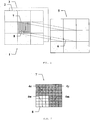
- a matrix 1 able to be personalized by means of a laser to produce a color image comprises a color layer 2, superimposed with a blackout layer 3 sensitive to the laser.
- the color layer 2 comprises an arrangement, typically periodic, of elements 4,4c, 4m, 4y, 4w, each of a single basic color, organized in sets or points 7 of the matrix 1.
- Each point 7 comprises at least part of an element 4 of each base color.
- a point 7 comprises at least once each of the n colors.
- the n colors form a colorimetric base.
- n is at least equal to 3.
- a point 7 of the matrix 1 comprises four square elements, each of one of the four colors: a cyan element 4c, a magenta element 4m, a yellow element (in English yellow) 4y and a white element (in English white) 4w .
- a point 7 of the matrix 1 comprises four elements, always with one of the four colors: cyan 4c, magenta 4m, yellow 4y and white 4w, arranged in line.
- Such an arrangement is advantageous in that it simplifies the production of the color layer 2, typically by offset printing.
- a blackout layer 3 is an initially transparent layer becoming dark as it receives a laser shot. At least one such blackout layer is arranged above and / or below the color layer 2, in order to allow direct and / or reflected blackout to be produced.
- An image 5 to be reproduced is spatially cut into points or pixels 6 according to the same arrangement (same number of rows and columns) as points 7 of the matrix 1.
- a point or pixel 6 of image 5 is associated with a point 7 of matrix 1.
- a pixel 6 of image 5 is a point 6 of image 5.
- a pixel 8 of the matrix 1 is significantly smaller.
- a pixel 8 of the image layer 2 is advantageously of the smallest achievable size, and is around 30 ⁇ m.
- the figure 3 illustrates linear elements of two pixels 8 in width. This pixel size 8 is still compatible with the resolution of the laser shooting process which is also of the order of 30 ⁇ m.
- a method of (re) producing a color image 5 spatially associates point to point said image 5 to (re) produce with a matrix 1, so that each point 7 of the matrix 1 is spatially associated with a point / pixel 6 of image 5.
- a point 6 of image 5 defines a hue.
- a colorimetric decomposition of this shade on the n basic colors of the colorimetric base of the matrix 1 provides a component, for each basic color.
- a pixel 8 of the matrix 1, of this basic color can then be obscured, by laser shooting, as a function of said component.
- the occultation is inversely proportional to said component, in order to express the residual base color according to this component.
- a pixel 8 of the matrix 1 is obscured at 70%.
- the matrix 1 has an arrangement, advantageously periodic, for example here according to elements 4c, 4m, 4y, 4w continuous linear of each of the n basic colors, for example here arranged horizontally relative to the image 5.
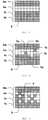
- the shape of at least one element 4c, 4m, 4y, 4w is modified. This is illustrated in the figure 4 .
- a modification 9a modifies the element 4m, normally magenta, with a pixel of the basic color of element 4c, that is cyan.
- modifications 9b, 9c modify the element 4w, normally white, with cyan pixels.
- a modification 9d modifies the element 4y, normally yellow, with a cyan pixel.
- a modification 9e affects element 4c, normally cyan, with a white pixel.
- an element 4c, 4m, 4y, 4w is superimposed, at least partially, and encroaches on an element of another color and imposes its color on it in the overlapping / encroachment zone. It follows that at least one pixel 8 of the matrix 1 is not of the predictable base color.
- This first characteristic produces a variation forming a detectable pattern, advantageously with the naked eye, or failing this by means of a magnifying glass.
- This detectable pattern acts as a signature characteristic of the producer or issuer of the matrix 1 and thus makes it possible to guarantee the origin of the origin of said matrix 1.
- this characteristic produces a security device which connects the matrix 1 to its producer / transmitter.
- This characteristic buried in the color layer 2 is relatively difficult to modify a posteriori, once the color layer 3 is integrated, with the blackout layer 3 and other optional layers in a matrix 1, typically by lamination.
- a modification 9 advantageously relates to a single color, here cyan, which encroaches on the other colors as illustrated by the modifications 9a-d or alternatively which disappears and is replaced by white as illustrated by the modification 9th.
- a modification 9 concerns an element 4 in that it encroaches and is superimposed with at least one other element 4, that is to say an element of another color.
- a 9th modification can only concern an absence of a color, however such a 9th modification is then hardly visible.
- a modification 9 advantageously encroaches on at least one element 4.
- the modified element 4 is superimposed with at most two other elements. These encroached elements are advantageously neighboring and contiguous with the modified element 4.
- the modified element 4 is chosen so as to be the most visible.
- the modified element 4 is chosen such that its color is the least present on average in the image 5.
- cyan is advantageous, in that it is generally absent or very little present, and this for all types of skin and / or hair color. It follows, according to the embodiment of the personalization, as described above, that a modification 9 of this color, substantially absent from the image 5, is then lasered in black.
- the modified element 4 is chosen so as to be the least visible.
- the modified element 4 is chosen such that its color is the most present on average in image 5.
- magenta is advantageous, in that it is generally very present, mainly in the skin and for all types of skin color. It follows, according to the embodiment of the personalization, as described above, that a modification 9 of this color is not laserized.
- the extent of the modification 9 is advantageously less than 12 pixels from the matrix 1, preferably less than 5 pixels.
- a modification 9 is such that it draws a symbol.
- such a symbol can advantageously be an alphanumeric symbol.
- a height of 4 pixels 8 of the matrix 1 makes it possible to draw certain alphanumeric characters.
- a height of 5 pixels 8 of the matrix 1 makes it possible to draw substantially all of the alphanumeric characters.
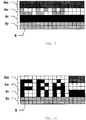
- the modification 9 draws an identifier of the issuer, preferably a monogram. So as shown in the figure 6 , a monogram comprising a series of 3 letters can be used to indicate the country issuing a travel or identity document. A series of 3 letters can typically be drawn on an extent less than or equal to 12 pixels 8.
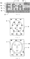
- the modification 9 is periodically repeated on the surface of the matrix 1. As illustrated in the figure 7 repetition over the entire surface of the matrix 1 may prove to be detrimental to a good “reading” of the image 5. Also according to an alternative illustrated in the figure 8 no modification 9 is arranged in at least one spared area 10. Said spared area 10 may for example be a central area. Thus, for an identity photo, the spared area 10 is advantageously an oval covering more or less the face, in order to leave intact the details (eyes, nose, mouth, etc.) useful for facial identification.
- the invention also relates to a method of personalizing such a matrix 1.
- a pixel 8 of the matrix 1 is personalized as a function of the tint of the corresponding pixel 6 of the image 5.
- a pixel 8 of the matrix 1 is thus lasered as a function of the component of said hue and the basic color of pixel 8.
- the base color of a pixel 8 is the predictable base color of this pixel 8, that is to say the color which it is deemed to have as a function of its position.
- a pixel 8 is deemed to have the color of the element 4c, 4m, 4y, 4w in which it is located.
- the primary characteristic of the invention is advantageously to modify this. So, with reference to the figure 4 , the pixel of modification 9a has, after modification, an effective cyan color, while its predictable color is magenta, since it is located in an area belonging to a 4m magenta element.
- a personalization method performs a concealment of a pixel 8 as a function of its effective color.
- the effective color of a modification 9 is different from the predictable color.
- This mode of personalization is advantageous in that personalization requires knowledge of the exact mapping of the matrix 1 including the modifications 9 applied. This knowledge can be obtained by reusing the cartography used during the realization of the matrix 1. This cartography is normally not accessible to a counterfeiter. This mapping can also be obtained by rereading the effective color of the color layer 2 of the matrix 1. Such a rereading requires sophisticated technology which is not necessarily accessible to a counterfeiter.
- the Figures 9 and 10 compare the two personalization methods, applied respectively to the same pattern, here the detail of matrix 1 of the figure 7 .
- Said pattern occupies two pixels 6 of image 5. It is assumed that the hue of these two pixels 6 is identical and decomposes with the following components: cyan 0%, magenta 50% and yellow 100%. Thus a pixel 8 of the matrix 1 of yellow color is in no way obscured, a pixel 8 magenta is obscured at 50% which is represented by a gray 50% and a pixel 8 in cyan is completely obscured which is represented by black .
- the figure 9 illustrates the result by considering the predictable colors of the pixels 8 of the matrix 1. While the figure 10 illustrates the result by considering the effective colors of the pixels 8.
- personalization according to the invention in that it takes into account the effective color of a modification 9 and the tint of the image 5 for the corresponding point 6, advantageously makes it possible to create a link between the matrix 1 and image 5 reproduced by personalization.
- a modification 9 of an element 4 makes it possible to link a matrix 1 to its emitting authority and thus guarantee its origin.
- the personalization process also makes it possible to link the matrix 1 to image 5.
- a personalization process combining the two previous personalization modes is advantageous in that it allows, by considering the predictable color, to hide the modifications 9 in certain areas of the image, and on the contrary, by considering the actual color, d '' accentuate the modifications 9 in other areas of the image.
- Such data can be a code thus advantageously hidden in the reproduced image in order to constitute a hidden signature.
- the absence of such a signature can make it possible to detect a forgery.
- a matrix 1 comprises a plurality of modifications 9.
- a scheduling of these modifications 9 makes it possible to define an order of succession / reading.
- the customization mode allows binary coding.
- a modification 9 personalized according to the effective color codes a 1, respectively a 0, while a modification 9 personalized according to the predictable color defines a 0, respectively a 1.
- a matrix 1 comprises N, for example 31, modifications 9.
- One of these modifications 9 is personalized according to the color effective, respectively predictable, and designates the coded number, while the other modifications 9 are personalized according to the predictable color, respectively effective.
- Such coded data can also advantageously include an attribute of a holder of the (document comprising the) security device.
- An example of an attribute is the date of birth of the wearer, which can be encoded by any of the methods previously described. This advantageously makes it possible to link the matrix 1 with the carrier, thus further strengthening the safety of the device.
Landscapes
- Physics & Mathematics (AREA)
- Health & Medical Sciences (AREA)
- Electromagnetism (AREA)
- General Health & Medical Sciences (AREA)
- Toxicology (AREA)
- Engineering & Computer Science (AREA)
- Manufacturing & Machinery (AREA)
- Credit Cards Or The Like (AREA)
- Thermal Transfer Or Thermal Recording In General (AREA)
Description
- La présente invention concerne un dispositif de sécurité. Ce dispositif de sécurité est plus particulièrement adapté à une matrice apte à être personnalisée au moyen d'un laser pour produire une image couleur. Un tel dispositif de sécurité sécurise une telle matrice et/ou une image couleur obtenue à partir d'une telle matrice.
- De manière connue, par exemple des documents
FR 11714352 FR 1103919 - Un procédé de (re)production d'une image couleur fait correspondre spatialement point à point ladite image à (re)produire à une matrice. Chaque point de la matrice comprend au moins une partie d'au moins un élément de chacune des couleurs de base. Chaque point correspondant de l'image définit une teinte. La décomposition colorimétrique de cette teinte sur les n couleurs de base de la base colorimétrique de la matrice fournit une composante, pour chaque couleur de base. Un élément de la matrice est occulté, par tir laser, en fonction de ladite composante.
- Une telle image couleur produite par personnalisation est avantageusement utilisée pour un document identitaire, par exemple pour réaliser une photo d'identité du porteur. Dans ce cadre il est avantageux de disposer d'un dispositif de sécurité afin de certifier l'origine de la matrice et/ou de l'image.
- Un dispositif de sécurité est un moyen difficile à reproduire afin de rendre la tâche d'un faussaire plus difficile, avantageusement contrôlable afin de pouvoir être vérifié et avantageusement lié au composant, ici la matrice et/ou l'image, afin de rendre détectable une éventuelle contrefaçon.
- Le document
US 2005/001419 A1 divulgue un dispositif de sécurité comprenant une matrice apte à être personnalisée au moyen d'un laser pour produire une image couleur. - L'invention propose un dispositif de sécurité lié à la matrice et un procédé de personnalisation permettant de lier un tel dispositif de sécurité à l'image et le cas échéant au porteur.
- L'invention a pour objet un dispositif de sécurité comprenant une matrice apte à être personnalisée au moyen d'un laser pour produire une image couleur, comprenant une couche couleur comportant des éléments, chacun d'une unique couleur de base, et au moins une couche occultante sensible au laser, où la forme d'au moins un élément est modifiée, l'élément modifié empiète, au moins partiellement, sur au moins un élément d'une autre couleur, la couleur de l'élément modifié étant appliquée dans la zone d'empiètement.
- Selon une autre caractéristique, l'élément modifié empiète sur au plus deux éléments.
- Selon une autre caractéristique, l'élément modifié est celui dont la couleur est la moins présente en moyenne dans l'image couleur.
- Selon une autre caractéristique, l'élément modifié est celui dont la couleur est la plus présente en moyenne dans l'image couleur.
- Selon une autre caractéristique, l'étendue d'une modification est inférieure à 12 pixels de la matrice, préférentiellement inférieure à 5 pixels.
- Selon une autre caractéristique, la modification dessine au moins un symbole alphanumérique.
- Selon une autre caractéristique, la modification dessine un identifiant de l'émetteur, préférentiellement un monogramme.
- Selon une autre caractéristique, la modification est périodiquement répétée dans la matrice.
- Selon une autre caractéristique, la modification épargne une zone de la matrice, préférentiellement une zone centrale.
- Selon une autre caractéristique, les éléments sont des lignes présentant préférentiellement une largeur de deux pixels de la matrice.
- L'invention concerne encore un procédé de personnalisation d'une matrice selon l'une quelconque des revendications précédentes, où au moins un pixel de la matrice est personnalisé en fonction de la teinte du pixel correspondant de l'image et de la couleur effective du pixel de la matrice, dans lequel au moins un pixel d'au moins une modification est personnalisé en fonction de la teinte du pixel correspondant de l'image et de la couleur prévisible du pixel.
- Selon une autre caractéristique, une modification est sélectivement personnalisée en considérant la couleur effective des pixels ou la couleur prévisible des pixels de telle manière à coder au moins une donnée.
- Selon une autre caractéristique, ladite au moins une donnée comprend un attribut d'un porteur.
- D'autres caractéristiques, détails et avantages de l'invention ressortiront plus clairement de la description détaillée donnée ci-après à titre indicatif en relation avec des dessins sur lesquels :
- la
figure 1 illustre une matrice et sa correspondance avec une image, - la
figure 2 illustre un premier arrangement des éléments de couleur d'une matrice, - la
figure 3 illustre un autre arrangement des éléments de couleur d'une matrice, - la
figure 4 illustre une première caractéristique de l'invention, - la
figure 5 illustre une utilisation de l'invention pour former un symbole, - la
figure 6 illustre une utilisation de l'invention pour former un monogramme, - la
figure 7 illustre une utilisation périodique de l'invention, - la
figure 8 illustre une épargne sur une partie de la matrice, - les
figures 9 et 10 illustrent deux modes de réalisation du tir laser de personnalisation. - Afin que l'invention soit mieux comprise, quelques rappels peuvent être utiles. Telle qu'illustrée à la
figure 1 , une matrice 1 apte à être personnalisée au moyen d'un laser pour produire une image couleur comprend une couche couleur 2, superposée avec une couche occultante 3 sensible au laser. La couche couleur 2 comprend un arrangement, typiquement périodique, d'éléments 4,4c,4m,4y,4w, chacun d'une unique couleur de base, organisés en ensembles ou points 7 de la matrice 1. Chaque point 7 comporte au moins une partie d'un élément 4 de chaque couleur de base. Ainsi un point 7 comporte au moins une fois chacune des n couleurs. Les n couleurs forment une base colorimétrique. Aussi n est au moins égal à 3. Une base colorimétrique couramment employée comporte les n = 4 couleurs : Blanc, Cyan, Jaune et Magenta, avantageusement disposées dans cet ordre. - Selon un premier arrangement, illustré à la
figure 2 , un point 7 de la matrice 1 comprend quatre éléments carrés, chacun d'une des quatre couleurs : un élément cyan 4c, un élément magenta 4m, un élément jaune (en anglais yellow) 4y et un élément blanc (en anglais white) 4w. - Selon un autre arrangement, illustré à la
figure 3 , un point 7 de la matrice 1 comprend quatre éléments, avec toujours un d'une des quatre couleurs : cyan 4c, magenta 4m, jaune 4y et blanc 4w, disposés en ligne. Un tel arrangement est avantageux en ce qu'il simplifie la réalisation de la couche couleur 2, typiquement par impression offset. - Une couche occultante 3 est une couche initialement transparente devenant sombre à mesure qu'elle reçoit un tir laser. Au moins une telle couche occultante est disposée au-dessus et/ou au-dessous de la couche couleur 2, afin de permettre la réalisation d'une occultation directe et/ou réfléchie.
- Une image 5 à reproduire est spatialement découpée en points ou pixels 6 selon une même disposition (même nombre de lignes et de colonnes) que les points 7 de la matrice 1. Un point ou pixel 6 de l'image 5 est associé à un point 7 de la matrice 1.
- Il convient de noter que la définition d'un pixel, en tant que plus petit élément pertinent, est ici variable. Un pixel 6 de l'image 5 est un point 6 de l'image 5. Au contraire un pixel 8 de la matrice 1 est sensiblement plus petit. Une distinction peut être faire entre un pixel 8 de la couche couleur 2 ou un pixel de la couche occultante 3, cependant il est avantageux que les deux se correspondent. Un pixel 8 de la couche image 2 est avantageusement de la plus petite taille réalisable, et est d'environ 30 µm. La
figure 3 illustre des éléments linéaires de deux pixels 8 de largeur. Cette taille de pixel 8 est encore compatible de la résolution du procédé de tir laser qui est aussi de l'ordre de 30 µm. - Un procédé de (re)production d'une image couleur 5 associe spatialement point à point ladite image 5 à (re)produire à une matrice 1, de manière à ce que chaque point 7 de la matrice 1 soit spatialement associé à un point/pixel 6 de l'image 5. Un point 6 de l'image 5 définit une teinte. Une décomposition colorimétrique de cette teinte sur les n couleurs de base de la base colorimétrique de la matrice 1 fournit une composante, pour chaque couleur de base. Un pixel 8 de la matrice 1, de cette couleur de base, peut alors être occulté, par tir laser, en fonction de ladite composante. L'occultation est inversement proportionnelle à ladite composante, afin d'exprimer la couleur de base résiduelle selon cette composante. Ainsi pour un pixel 6 de l'image 5 présentant une teinte comprenant 30% de la couleur de base jaune, un pixel 8 de la matrice 1 est occulté à 70%.
- Ces rappels étant donnés, l'invention va maintenant être décrite. Telle que montrée à la
figure 3 , la matrice 1 présente un arrangement, avantageusement périodique, par exemple ici selon des éléments 4c,4m,4y,4w linéaires continus de chacune des n couleurs de base, par exemple ici disposés horizontalement relativement à l'image 5. - Selon une caractéristique de l'invention la forme d'au moins un élément 4c,4m,4y,4w est modifiée. Ceci est illustré à la
figure 4 . Ainsi une modification 9a modifie l'élément 4m, normalement magenta, avec un pixel de la couleur de base de l'élément 4c, soit cyan. De même des modifications 9b,9c modifient l'élément 4w, normalement blanc, avec des pixels cyan. Une modification 9d modifie l'élément 4y, normalement jaune, avec un pixel cyan. Enfin une modification 9e affecte l'élément 4c, normalement cyan, avec un pixel blanc. - Ainsi un élément 4c,4m,4y,4w se superpose, au moins partiellement, et empiète sur un élément d'une autre couleur et lui impose sa couleur dans la zone de superposition/empiètement. Il s'ensuit qu'au moins un pixel 8 de la matrice 1 n'est pas de la couleur de base prévisible.
- Cette première caractéristique produit une variation formant un motif détectable, avantageusement à l'œil nu, ou à défaut au moyen d'une loupe. Ce motif détectable agit comme une signature caractéristique du producteur ou émetteur de la matrice 1 et permet ainsi de garantir l'origine de la provenance de ladite matrice 1.
- En ce sens cette caractéristique produit un dispositif de sécurité qui relie la matrice 1 à son producteur/émetteur. Cette caractéristique, enfouie dans la couche couleur 2 est relativement difficile à modifier a posteriori, une fois la couche couleur 3 intégrée, avec la couche occultante 3 et d'autres couches éventuelles dans une matrice 1, typiquement par lamination.
- Comme illustré dans les exemples précédents, une modification 9 concerne avantageusement une unique couleur, ici le cyan, qui empiète sur les autres couleurs telle qu'illustrée par les modifications 9a-d ou alternativement qui disparait et est remplacée par du blanc comme illustré par la modification 9e.
- Une modification 9 concerne un élément 4 en ce qu'il empiète et se superpose avec au moins un autre élément 4, soit un élément d'une autre couleur. Une modification 9e peut uniquement concerner une absence d'une couleur, cependant une telle modification 9e est alors peu visible. Aussi une modification 9 empiète avantageusement sur au moins un élément 4.
- Selon une autre caractéristique, afin que la modification 9 ne présente pas une étendue trop importante, au risque de déformer ou de rendre l'image 5 peu visible, l'élément 4 modifié se superpose avec au plus deux autres éléments. Ces éléments empiétés sont avantageusement voisins et contigus avec l'élément 4 modifié.
- Selon une caractéristique avantageuse, l'élément 4 modifié est choisi de manière à être le plus visible. Pour cela, l'élément 4 modifié est choisi tel que sa couleur soit la moins présente en moyenne dans l'image 5. Ainsi, pour une image 5 photo d'identité, le cyan est avantageux, en ce qu'il est généralement absent ou très peu présent, et ce pour tous les types de couleur de peaux et/ou de cheveux. Il s'ensuit, selon le mode de réalisation de la personnalisation, tel que décrit plus avant, qu'une modification 9 de cette couleur, sensiblement absente de l'image 5, est alors lasérisée en noir.
- Selon une caractéristique alternative, l'élément 4 modifié est choisi de manière à être le moins visible. Pour cela, l'élément 4 modifié est choisi tel que sa couleur soit la plus présente en moyenne dans l'image 5. Ainsi, pour une image 5 photo d'identité, le magenta est avantageux, en ce qu'il est généralement très présent, principalement dans la peau et ce pour tous les types de couleur de peaux. Il s'ensuit, selon le mode de réalisation de la personnalisation, tel que décrit plus avant, qu'une modification 9 de cette couleur n'est pas lasérisée.
- Selon une autre caractéristique, afin de limiter l'étendue de la modification 9 et donc son impact sur l'image 5, l'étendue de la modification 9 est avantageusement inférieure à 12 pixels de la matrice 1, préférentiellement inférieure à 5 pixels.
- Selon un mode de réalisation, plus particulièrement illustré à la
figure 5 , une modification 9 est telle qu'elle dessine un symbole. - Selon un mode de réalisation un tel symbole peut avantageusement être un symbole alphanumérique. Tel qu'illustré à la
figure 5 une hauteur de 4 pixels 8 de la matrice 1 permet de dessiner certains caractères alphanumériques. Tel qu'illustré à lafigure 6 une hauteur de 5 pixels 8 de la matrice 1 permet de dessiner sensiblement tous les caractères alphanumériques. - Selon une autre caractéristique, la modification 9 dessine un identifiant de l'émetteur, préférentiellement un monogramme. Ainsi, tel qu'illustré à la
figure 6 , un monogramme comprenant une suite de 3 lettres peut être utilisé pour indiquer le pays émetteur d'un document de voyage ou d'identité. Une suite de 3 lettres peut typiquement être dessinée sur une étendue inférieure ou égale à 12 pixels 8. - Selon un mode de réalisation, illustré aux
figures 7 et 8 , la modification 9 est périodiquement répétée sur la surface de la matrice 1. Tel qu'illustré à lafigure 7 une répétition sur la totalité de la surface de la matrice 1 peut s'avérer préjudiciable à une bonne « lecture » de l'image 5. Aussi selon une alternative illustrée à lafigure 8 aucune modification 9 n'est disposée dans au moins une zone épargnée 10. Ladite zone 10 épargnée peut être par exemple une zone centrale. Ainsi, pour une photo d'identité, la zone épargnée 10 est avantageusement un ovale recouvrant peu ou prou le visage, afin de laisser intacts les détails (yeux, nez, bouche, etc.) utiles pour une identification faciale. - L'invention concerne encore un procédé de personnalisation d'une telle matrice 1.
- De manière classique, comme il a été décrit précédemment, un pixel 8 de la matrice 1 est personnalisé en fonction de la teinte du pixel 6 correspondant de l'image 5. Un pixel 8 de la matrice 1 est ainsi lasérisé en fonction de la composante de ladite teinte et de la couleur de base du pixel 8.
- De manière classique, la couleur de base d'un pixel 8 est la couleur de base prévisible de ce pixel 8, soit la couleur qu'il est réputé avoir en fonction de sa position. Ainsi un pixel 8 est réputé avoir la couleur de l'élément 4c,4m,4y,4w dans lequel il se trouve. Or la caractéristique première de l'invention est avantageusement de modifier cela. Ainsi, en référence à la
figure 4 , le pixel de la modification 9a présente, après modification, une couleur effective cyan, alors que sa couleur prévisible est magenta, puisqu'il est situé dans une zone appartenant à un élément magenta 4m. - Il est possible d'utiliser un procédé de personnalisation classique, sans tenir compte des modifications 9, soit en considérant que chaque pixel 8 est de sa couleur prévisible. Un tel procédé, appliqué sans discernement, par exemple à toute l'image, est tel que typiquement utilisé par un faussaire. Ceci peut permettre de détecter une contrefaçon.
- Au contraire, un procédé de personnalisation selon l'invention réalise une occultation d'un pixel 8 en fonction de sa couleur effective. Selon l'invention, la couleur effective d'une modification 9 est différente de la couleur prévisible. Ce mode de personnalisation est avantageux en ce que la personnalisation nécessite une connaissance de la cartographie exacte de la matrice 1 y compris les modifications 9 appliquées. Cette connaissance peut être obtenue en réutilisant la cartographie utilisée lors de la réalisation de la matrice 1. Cette cartographie n'est normalement pas accessible à un faussaire. Cette cartographie peut encore être obtenue en relisant la couleur effective de la couche couleur 2 de la matrice 1. Une telle relecture nécessite une technologie pointue qui n'est pas nécessairement accessible à un faussaire.
- Il est encore, selon l'invention, possible de panacher les deux modes de personnalisation précédents.
- Les
figures 9 et 10 illustrent comparativement les deux procédés de personnalisation, appliqués respectivement à un même motif, ici le détail de matrice 1 de lafigure 7 . Ledit motif occupe deux pixels 6 de l'image 5. Il est supposé que la teinte de ces deux pixels 6 est identique et se décompose avec les composantes suivantes : cyan 0%, magenta 50% et jaune 100%. Ainsi un pixel 8 de la matrice 1 de couleur jaune n'est aucunement occulté, un pixel 8 magenta est occulté à 50% ce qui est figuré par un grisé 50% et un pixel 8 cyan est totalement occulté ce qui est figuré par du noir. - La
figure 9 illustre le résultat en considérant les couleurs prévisibles des pixels 8 de la matrice 1. Tandis que lafigure 10 illustre le résultat en considérant les couleurs effectives des pixels 8. - Il apparait qu'une personnalisation selon la couleur prévisible a tendance à masquer les modifications 9, alors qu'une personnalisation selon la couleur effective a, au contraire, tendance à souligner les modifications 9. Ceci permet de rendre visible le procédé de personnalisation utilisé et ainsi de détecter une contrefaçon.
- Surtout, une personnalisation selon l'invention, en ce qu'elle prend en compte la couleur effective d'une modification 9 et la teinte de l'image 5 pour le point 6 correspondant, permet avantageusement de créer un lien entre la matrice 1 et l'image 5 reproduite par la personnalisation.
- Telle que décrite précédemment, une modification 9 d'un élément 4 permet de lier une matrice 1 à son autorité émettrice et ainsi garantir son origine.
- Le procédé de personnalisation permet, de plus, de lier la matrice 1 à l'image 5.
- Un procédé de personnalisation panachant les deux modes de personnalisation précédents est avantageux en ce qu'il permet, en considérant la couleur prévisible, de masquer les modifications 9 dans certaines zones de l'image, et au contraire, en considérant la couleur effective, d'accentuer les modifications 9 dans d'autres zones de l'image.
- Ceci peut être avantageusement mis à profit pour sélectivement personnaliser certaines modifications 9 selon la couleur effective ou selon la couleur prévisible de telle manière à réaliser un codage, par exemple d'une donnée.
- Une telle donnée peut être un code ainsi avantageusement dissimulé dans l'image reproduite afin de constituer une signature cachée. L'absence d'une telle signature peut permettre de détecter une contrefaçon.
- Selon un premier mode de réalisation, une matrice 1 comprend une pluralité de modifications 9. Un ordonnancement de ces modifications 9 permet de définir un ordre de succession/lecture. Le mode de personnalisation autorise un codage binaire. Ainsi une modification 9 personnalisée selon la couleur effective code un 1, respectivement un 0, tandis qu'une modification 9 personnalisée selon la couleur prévisible définit un 0, respectivement un 1.
- Selon un autre mode de réalisation, plus particulièrement adapté au codage d'un nombre parmi N, tel par exemple un tantième de date, une matrice 1 comprend N, par exemple 31, modifications 9. Une de ces modifications 9 est personnalisée selon la couleur effective, respectivement prévisible, et désigne le nombre codé, tandis que les autres modifications 9 sont personnalisées selon la couleur prévisible, respectivement effective.
- Tout autre mode de codage imaginable par l'homme du métier peut encore être utilisé.
- Une telle donnée codée peut encore avantageusement comprendre un attribut d'un porteur du (document comprenant le) dispositif de sécurité. Un exemple d'attribut est la date de naissance du porteur, qui peut être codée par l'une quelconque des méthodes précédemment décrites. Ceci permet avantageusement de lier la matrice 1 avec le porteur, renforçant encore ainsi la sécurité du dispositif.
Claims (14)
- Dispositif de sécurité comprenant une matrice (1) apte à être personnalisée au moyen d'un laser pour produire une image couleur (5), comprenant une couche couleur (2) comportant des éléments (4), chacun d'une unique couleur de base, et au moins une couche occultante (3) sensible au laser,
caractérisé en ce que la forme d'au moins un élément (4) est modifiée pour comporter une modification (9) empiétant au moins partiellement sur au moins un autre élément (4) d'une autre couleur, ledit au moins un élément modifié imposant sa couleur dans la zone d'empiètement. - Dispositif selon la revendication 1, où l'élément (4) modifié empiète sur au plus deux éléments (4).
- Dispositif selon la revendication 2, dans lequel lesdits éléments (4) empiétés sont voisins et contigus avec l'élément modifié (4).
- Dispositif selon l'une quelconque des revendications 1 à 3, où l'élément (4) modifié est celui dont la couleur est la moins présente en moyenne dans l'image couleur (5).
- Dispositif selon l'une quelconque des revendications 1 à 3, où l'élément (4) modifié est celui dont la couleur est la plus présente en moyenne dans l'image couleur (5).
- Dispositif selon l'une quelconque des revendications 1 à 5, où l'étendue de la modification (9) est inférieure à 12 pixels (8) de la matrice (1), préférentiellement inférieure à 5 pixels (8).
- Dispositif selon l'une quelconque des revendications 1 à 6, où la modification (9) dessine au moins un symbole alphanumérique.
- Dispositif selon l'une quelconque des revendications 1 à 7, où la modification (9) dessine un identifiant de l'émetteur, préférentiellement un monogramme.
- Dispositif selon l'une quelconque des revendications 1 à 8, où la modification (9) est périodiquement répétée dans la matrice (1).
- Dispositif selon l'une quelconque des revendications 1 à 9, où la modification (9) épargne une zone (10) de la matrice (1), préférentiellement une zone (10) centrale.
- Dispositif selon l'une quelconque des revendications 1 à 10, où les éléments (4c,4m,4y,4w) sont des lignes, et présentent préférentiellement une largeur de deux pixels (8) de la matrice (1).
- Procédé de personnalisation d'une matrice (1) d'un dispositif de sécurité selon l'une quelconque des revendications précédentes, caractérisé en ce que au moins un pixel (8) de la matrice (1) est personnalisé en fonction de la teinte du pixel (6) correspondant de l'image (5) et de la couleur effective du pixel (8) de la matrice (1),
dans lequel au moins un pixel (8) d'au moins une modification (9) est personnalisé en fonction de la teinte du pixel (6) correspondant de l'image (5) et de la couleur prévisible du pixel (8). - Procédé de personnalisation selon la revendication 12, où une modification (9) est sélectivement personnalisée en considérant la couleur effective des pixels (8) ou la couleur prévisible des pixels (8) de telle manière à coder au moins une donnée.
- Procédé de personnalisation selon la revendication 13, où ladite au moins une donnée comprend un attribut d'un porteur.
Applications Claiming Priority (2)
| Application Number | Priority Date | Filing Date | Title |
|---|---|---|---|
| FR1560172A FR3042735B1 (fr) | 2015-10-23 | 2015-10-23 | Dispositif de securite pour une matrice apte a etre personnalisee au moyen d'un laser pour produire une image couleur |
| PCT/FR2016/052747 WO2017068304A1 (fr) | 2015-10-23 | 2016-10-21 | Dispositif de sécurité pour une matrice apte à être personnalisée au moyen d'un laser pour produire une image couleur |
Publications (2)
| Publication Number | Publication Date |
|---|---|
| EP3365183A1 EP3365183A1 (fr) | 2018-08-29 |
| EP3365183B1 true EP3365183B1 (fr) | 2020-01-29 |
Family
ID=55542757
Family Applications (1)
| Application Number | Title | Priority Date | Filing Date |
|---|---|---|---|
| EP16798245.3A Active EP3365183B1 (fr) | 2015-10-23 | 2016-10-21 | Dispositif de sécurité pour une matrice apte à être personnalisée au moyen d'un laser pour produire une image couleur |
Country Status (3)
| Country | Link |
|---|---|
| EP (1) | EP3365183B1 (fr) |
| FR (1) | FR3042735B1 (fr) |
| WO (1) | WO2017068304A1 (fr) |
Family Cites Families (3)
| Publication number | Priority date | Publication date | Assignee | Title |
|---|---|---|---|---|
| US7763179B2 (en) * | 2003-03-21 | 2010-07-27 | Digimarc Corporation | Color laser engraving and digital watermarking |
| FR2998063B1 (fr) * | 2012-11-15 | 2018-04-06 | Idemia France | Agencement de pixels pour realisation d'une image couleur par laser |
| FR3006238B1 (fr) * | 2013-05-28 | 2015-06-19 | Oberthur Technologies | Arrangement pour et procede de realisation d'une image en couleur |
-
2015
- 2015-10-23 FR FR1560172A patent/FR3042735B1/fr not_active Expired - Fee Related
-
2016
- 2016-10-21 EP EP16798245.3A patent/EP3365183B1/fr active Active
- 2016-10-21 WO PCT/FR2016/052747 patent/WO2017068304A1/fr not_active Ceased
Non-Patent Citations (1)
| Title |
|---|
| None * |
Also Published As
| Publication number | Publication date |
|---|---|
| EP3365183A1 (fr) | 2018-08-29 |
| WO2017068304A1 (fr) | 2017-04-27 |
| FR3042735B1 (fr) | 2019-08-02 |
| FR3042735A1 (fr) | 2017-04-28 |
Similar Documents
| Publication | Publication Date | Title |
|---|---|---|
| EP1291195B1 (fr) | Elément de contrôle pour objets imprimés | |
| EP1319219B1 (fr) | Procede destine a prevenir la contrefaçon ou l'alteration d'une surface imprimee ou gravee | |
| EP2162295B1 (fr) | Document de sécurité en forme de livret, avec une page additionnelle de révélation d'une information cachée. | |
| EP1597083A2 (fr) | Element de securite et procede d' impression | |
| FR3112097A1 (fr) | Document d’identité en format livret comportant un dispositif de sécurité à matériau optiquement variable | |
| EP2275279A1 (fr) | Document de sécurité et procédé de vérification de ce document | |
| FR3142936A1 (fr) | Mesures préventives contre la copie et l’altération de document à gratter | |
| EP2445726B1 (fr) | Document de sécurité à zones tactiles différenciées, et procédé pour sa fabrication | |
| EP3365183B1 (fr) | Dispositif de sécurité pour une matrice apte à être personnalisée au moyen d'un laser pour produire une image couleur | |
| OA13231A (fr) | Procédé de réalisation d'un motif luminescent à partir de points sans recouvrement, et motif luminescent correspondant. | |
| EP4076974B1 (fr) | Procédé de fabrication d'un document électronique comportant une bande magnétique cachée et document électronique obtenu | |
| WO2010070089A1 (fr) | Élément anti-contrefaçon pour document d'identification, procédé pour fabriquer un tel élément, et document d'identification sécurisé | |
| CA2982878C (fr) | Procede de verification d'un dispositif de securite comportant une signature | |
| EP2318217B1 (fr) | Document fiduciaire ou assimile comportant des motifs sous forme d'a-plats ainsi qu'une impression en taille douce, et son procede de fabrication | |
| EP1015254A1 (fr) | Document fiduciaire revetu d'impressions de securite | |
| JP5990791B2 (ja) | 偽造防止用印刷物 | |
| EP3271192A1 (fr) | Element de securite et document securise | |
| JP2020037215A (ja) | 潜像印刷物 | |
| EP3782060B1 (fr) | Procédé pour authentifier un document securisé | |
| EP1847400B1 (fr) | Elément de controle pour objets imprimés | |
| WO2020119986A1 (fr) | Document de sécurité intégrant un motif de contrôle | |
| JP2006167955A (ja) | 透かし入りカード | |
| CN100452087C (zh) | 用于证件和票据的个人或个性视读信息加载保护方法 | |
| JP2007015320A (ja) | 彩紋の一部に文字を有する印刷物 | |
| EP2189294A1 (fr) | Procédé pour élaborer une image guillochée, procédé pour vérifier l'authenticité et/ou imprimer ladite image sur un support et support associé |
Legal Events
| Date | Code | Title | Description |
|---|---|---|---|
| STAA | Information on the status of an ep patent application or granted ep patent |
Free format text: STATUS: UNKNOWN |
|
| STAA | Information on the status of an ep patent application or granted ep patent |
Free format text: STATUS: THE INTERNATIONAL PUBLICATION HAS BEEN MADE |
|
| PUAI | Public reference made under article 153(3) epc to a published international application that has entered the european phase |
Free format text: ORIGINAL CODE: 0009012 |
|
| STAA | Information on the status of an ep patent application or granted ep patent |
Free format text: STATUS: REQUEST FOR EXAMINATION WAS MADE |
|
| 17P | Request for examination filed |
Effective date: 20180411 |
|
| AK | Designated contracting states |
Kind code of ref document: A1 Designated state(s): AL AT BE BG CH CY CZ DE DK EE ES FI FR GB GR HR HU IE IS IT LI LT LU LV MC MK MT NL NO PL PT RO RS SE SI SK SM TR |
|
| AX | Request for extension of the european patent |
Extension state: BA ME |
|
| DAV | Request for validation of the european patent (deleted) | ||
| DAX | Request for extension of the european patent (deleted) | ||
| GRAP | Despatch of communication of intention to grant a patent |
Free format text: ORIGINAL CODE: EPIDOSNIGR1 |
|
| STAA | Information on the status of an ep patent application or granted ep patent |
Free format text: STATUS: GRANT OF PATENT IS INTENDED |
|
| INTG | Intention to grant announced |
Effective date: 20190822 |
|
| GRAS | Grant fee paid |
Free format text: ORIGINAL CODE: EPIDOSNIGR3 |
|
| GRAA | (expected) grant |
Free format text: ORIGINAL CODE: 0009210 |
|
| STAA | Information on the status of an ep patent application or granted ep patent |
Free format text: STATUS: THE PATENT HAS BEEN GRANTED |
|
| AK | Designated contracting states |
Kind code of ref document: B1 Designated state(s): AL AT BE BG CH CY CZ DE DK EE ES FI FR GB GR HR HU IE IS IT LI LT LU LV MC MK MT NL NO PL PT RO RS SE SI SK SM TR |
|
| REG | Reference to a national code |
Ref country code: GB Ref legal event code: FG4D Free format text: NOT ENGLISH |
|
| REG | Reference to a national code |
Ref country code: CH Ref legal event code: EP |
|
| REG | Reference to a national code |
Ref country code: AT Ref legal event code: REF Ref document number: 1228224 Country of ref document: AT Kind code of ref document: T Effective date: 20200215 |
|
| REG | Reference to a national code |
Ref country code: IE Ref legal event code: FG4D Free format text: LANGUAGE OF EP DOCUMENT: FRENCH |
|
| REG | Reference to a national code |
Ref country code: DE Ref legal event code: R096 Ref document number: 602016028848 Country of ref document: DE |
|
| REG | Reference to a national code |
Ref country code: NL Ref legal event code: MP Effective date: 20200129 Ref country code: NL Ref legal event code: NE Effective date: 20200518 |
|
| REG | Reference to a national code |
Ref country code: CH Ref legal event code: NV Representative=s name: BOVARD AG PATENT- UND MARKENANWAELTE, CH |
|
| REG | Reference to a national code |
Ref country code: CH Ref legal event code: PCOW Free format text: NEW ADDRESS: 2, PLACE SAMUEL DE CHAMPLAIN, 92400 COURBEVOIE (FR) |
|
| PG25 | Lapsed in a contracting state [announced via postgrant information from national office to epo] |
Ref country code: PT Free format text: LAPSE BECAUSE OF FAILURE TO SUBMIT A TRANSLATION OF THE DESCRIPTION OR TO PAY THE FEE WITHIN THE PRESCRIBED TIME-LIMIT Effective date: 20200621 Ref country code: FI Free format text: LAPSE BECAUSE OF FAILURE TO SUBMIT A TRANSLATION OF THE DESCRIPTION OR TO PAY THE FEE WITHIN THE PRESCRIBED TIME-LIMIT Effective date: 20200129 Ref country code: RS Free format text: LAPSE BECAUSE OF FAILURE TO SUBMIT A TRANSLATION OF THE DESCRIPTION OR TO PAY THE FEE WITHIN THE PRESCRIBED TIME-LIMIT Effective date: 20200129 Ref country code: NO Free format text: LAPSE BECAUSE OF FAILURE TO SUBMIT A TRANSLATION OF THE DESCRIPTION OR TO PAY THE FEE WITHIN THE PRESCRIBED TIME-LIMIT Effective date: 20200429 Ref country code: NL Free format text: LAPSE BECAUSE OF FAILURE TO SUBMIT A TRANSLATION OF THE DESCRIPTION OR TO PAY THE FEE WITHIN THE PRESCRIBED TIME-LIMIT Effective date: 20200129 |
|
| REG | Reference to a national code |
Ref country code: LT Ref legal event code: MG4D |
|
| REG | Reference to a national code |
Ref country code: NL Ref legal event code: FP |
|
| PG25 | Lapsed in a contracting state [announced via postgrant information from national office to epo] |
Ref country code: GR Free format text: LAPSE BECAUSE OF FAILURE TO SUBMIT A TRANSLATION OF THE DESCRIPTION OR TO PAY THE FEE WITHIN THE PRESCRIBED TIME-LIMIT Effective date: 20200430 Ref country code: SE Free format text: LAPSE BECAUSE OF FAILURE TO SUBMIT A TRANSLATION OF THE DESCRIPTION OR TO PAY THE FEE WITHIN THE PRESCRIBED TIME-LIMIT Effective date: 20200129 Ref country code: LV Free format text: LAPSE BECAUSE OF FAILURE TO SUBMIT A TRANSLATION OF THE DESCRIPTION OR TO PAY THE FEE WITHIN THE PRESCRIBED TIME-LIMIT Effective date: 20200129 Ref country code: BG Free format text: LAPSE BECAUSE OF FAILURE TO SUBMIT A TRANSLATION OF THE DESCRIPTION OR TO PAY THE FEE WITHIN THE PRESCRIBED TIME-LIMIT Effective date: 20200429 Ref country code: IS Free format text: LAPSE BECAUSE OF FAILURE TO SUBMIT A TRANSLATION OF THE DESCRIPTION OR TO PAY THE FEE WITHIN THE PRESCRIBED TIME-LIMIT Effective date: 20200529 Ref country code: HR Free format text: LAPSE BECAUSE OF FAILURE TO SUBMIT A TRANSLATION OF THE DESCRIPTION OR TO PAY THE FEE WITHIN THE PRESCRIBED TIME-LIMIT Effective date: 20200129 |
|
| PG25 | Lapsed in a contracting state [announced via postgrant information from national office to epo] |
Ref country code: DK Free format text: LAPSE BECAUSE OF FAILURE TO SUBMIT A TRANSLATION OF THE DESCRIPTION OR TO PAY THE FEE WITHIN THE PRESCRIBED TIME-LIMIT Effective date: 20200129 Ref country code: ES Free format text: LAPSE BECAUSE OF FAILURE TO SUBMIT A TRANSLATION OF THE DESCRIPTION OR TO PAY THE FEE WITHIN THE PRESCRIBED TIME-LIMIT Effective date: 20200129 Ref country code: LT Free format text: LAPSE BECAUSE OF FAILURE TO SUBMIT A TRANSLATION OF THE DESCRIPTION OR TO PAY THE FEE WITHIN THE PRESCRIBED TIME-LIMIT Effective date: 20200129 Ref country code: SK Free format text: LAPSE BECAUSE OF FAILURE TO SUBMIT A TRANSLATION OF THE DESCRIPTION OR TO PAY THE FEE WITHIN THE PRESCRIBED TIME-LIMIT Effective date: 20200129 Ref country code: RO Free format text: LAPSE BECAUSE OF FAILURE TO SUBMIT A TRANSLATION OF THE DESCRIPTION OR TO PAY THE FEE WITHIN THE PRESCRIBED TIME-LIMIT Effective date: 20200129 Ref country code: SM Free format text: LAPSE BECAUSE OF FAILURE TO SUBMIT A TRANSLATION OF THE DESCRIPTION OR TO PAY THE FEE WITHIN THE PRESCRIBED TIME-LIMIT Effective date: 20200129 Ref country code: EE Free format text: LAPSE BECAUSE OF FAILURE TO SUBMIT A TRANSLATION OF THE DESCRIPTION OR TO PAY THE FEE WITHIN THE PRESCRIBED TIME-LIMIT Effective date: 20200129 |
|
| REG | Reference to a national code |
Ref country code: DE Ref legal event code: R097 Ref document number: 602016028848 Country of ref document: DE |
|
| REG | Reference to a national code |
Ref country code: AT Ref legal event code: MK05 Ref document number: 1228224 Country of ref document: AT Kind code of ref document: T Effective date: 20200129 |
|
| PLBE | No opposition filed within time limit |
Free format text: ORIGINAL CODE: 0009261 |
|
| STAA | Information on the status of an ep patent application or granted ep patent |
Free format text: STATUS: NO OPPOSITION FILED WITHIN TIME LIMIT |
|
| 26N | No opposition filed |
Effective date: 20201030 |
|
| PG25 | Lapsed in a contracting state [announced via postgrant information from national office to epo] |
Ref country code: IT Free format text: LAPSE BECAUSE OF FAILURE TO SUBMIT A TRANSLATION OF THE DESCRIPTION OR TO PAY THE FEE WITHIN THE PRESCRIBED TIME-LIMIT Effective date: 20200129 Ref country code: AT Free format text: LAPSE BECAUSE OF FAILURE TO SUBMIT A TRANSLATION OF THE DESCRIPTION OR TO PAY THE FEE WITHIN THE PRESCRIBED TIME-LIMIT Effective date: 20200129 |
|
| PG25 | Lapsed in a contracting state [announced via postgrant information from national office to epo] |
Ref country code: SI Free format text: LAPSE BECAUSE OF FAILURE TO SUBMIT A TRANSLATION OF THE DESCRIPTION OR TO PAY THE FEE WITHIN THE PRESCRIBED TIME-LIMIT Effective date: 20200129 Ref country code: PL Free format text: LAPSE BECAUSE OF FAILURE TO SUBMIT A TRANSLATION OF THE DESCRIPTION OR TO PAY THE FEE WITHIN THE PRESCRIBED TIME-LIMIT Effective date: 20200129 |
|
| PG25 | Lapsed in a contracting state [announced via postgrant information from national office to epo] |
Ref country code: MC Free format text: LAPSE BECAUSE OF FAILURE TO SUBMIT A TRANSLATION OF THE DESCRIPTION OR TO PAY THE FEE WITHIN THE PRESCRIBED TIME-LIMIT Effective date: 20200129 Ref country code: LU Free format text: LAPSE BECAUSE OF NON-PAYMENT OF DUE FEES Effective date: 20201021 |
|
| REG | Reference to a national code |
Ref country code: BE Ref legal event code: MM Effective date: 20201031 |
|
| PG25 | Lapsed in a contracting state [announced via postgrant information from national office to epo] |
Ref country code: BE Free format text: LAPSE BECAUSE OF NON-PAYMENT OF DUE FEES Effective date: 20201031 |
|
| PG25 | Lapsed in a contracting state [announced via postgrant information from national office to epo] |
Ref country code: IE Free format text: LAPSE BECAUSE OF NON-PAYMENT OF DUE FEES Effective date: 20201021 |
|
| PG25 | Lapsed in a contracting state [announced via postgrant information from national office to epo] |
Ref country code: TR Free format text: LAPSE BECAUSE OF FAILURE TO SUBMIT A TRANSLATION OF THE DESCRIPTION OR TO PAY THE FEE WITHIN THE PRESCRIBED TIME-LIMIT Effective date: 20200129 Ref country code: MT Free format text: LAPSE BECAUSE OF FAILURE TO SUBMIT A TRANSLATION OF THE DESCRIPTION OR TO PAY THE FEE WITHIN THE PRESCRIBED TIME-LIMIT Effective date: 20200129 Ref country code: CY Free format text: LAPSE BECAUSE OF FAILURE TO SUBMIT A TRANSLATION OF THE DESCRIPTION OR TO PAY THE FEE WITHIN THE PRESCRIBED TIME-LIMIT Effective date: 20200129 |
|
| PG25 | Lapsed in a contracting state [announced via postgrant information from national office to epo] |
Ref country code: MK Free format text: LAPSE BECAUSE OF FAILURE TO SUBMIT A TRANSLATION OF THE DESCRIPTION OR TO PAY THE FEE WITHIN THE PRESCRIBED TIME-LIMIT Effective date: 20200129 Ref country code: AL Free format text: LAPSE BECAUSE OF FAILURE TO SUBMIT A TRANSLATION OF THE DESCRIPTION OR TO PAY THE FEE WITHIN THE PRESCRIBED TIME-LIMIT Effective date: 20200129 |
|
| REG | Reference to a national code |
Ref country code: DE Ref legal event code: R082 Ref document number: 602016028848 Country of ref document: DE Representative=s name: CBDL PATENTANWAELTE GBR, DE Ref country code: DE Ref legal event code: R082 Ref document number: 602016028848 Country of ref document: DE Representative=s name: CBDL PATENTANWAELTE EGBR, DE |
|
| P01 | Opt-out of the competence of the unified patent court (upc) registered |
Effective date: 20230428 |
|
| REG | Reference to a national code |
Ref country code: NL Ref legal event code: PD Owner name: IDEMIA IDENTITY & SECURITY FRANCE; FR Free format text: DETAILS ASSIGNMENT: CHANGE OF OWNER(S), ASSIGNMENT; FORMER OWNER NAME: IDEMIA FRANCE Effective date: 20250606 |
|
| REG | Reference to a national code |
Ref country code: GB Ref legal event code: 732E Free format text: REGISTERED BETWEEN 20250612 AND 20250618 |
|
| REG | Reference to a national code |
Ref country code: CH Ref legal event code: PK Free format text: RECTIFICATIONS |
|
| PGFP | Annual fee paid to national office [announced via postgrant information from national office to epo] |
Ref country code: NL Payment date: 20250923 Year of fee payment: 10 |
|
| PGFP | Annual fee paid to national office [announced via postgrant information from national office to epo] |
Ref country code: GB Payment date: 20250923 Year of fee payment: 10 |
|
| PGFP | Annual fee paid to national office [announced via postgrant information from national office to epo] |
Ref country code: FR Payment date: 20250924 Year of fee payment: 10 |
|
| PGFP | Annual fee paid to national office [announced via postgrant information from national office to epo] |
Ref country code: CZ Payment date: 20250929 Year of fee payment: 10 |
|
| REG | Reference to a national code |
Ref country code: CH Ref legal event code: U11 Free format text: ST27 STATUS EVENT CODE: U-0-0-U10-U11 (AS PROVIDED BY THE NATIONAL OFFICE) Effective date: 20251101 |
|
| PGFP | Annual fee paid to national office [announced via postgrant information from national office to epo] |
Ref country code: DE Payment date: 20250923 Year of fee payment: 10 |
|
| PGFP | Annual fee paid to national office [announced via postgrant information from national office to epo] |
Ref country code: CH Payment date: 20251101 Year of fee payment: 10 |