EP3365190B1 - Lenkerende - Google Patents
Lenkerende Download PDFInfo
- Publication number
- EP3365190B1 EP3365190B1 EP16782080.2A EP16782080A EP3365190B1 EP 3365190 B1 EP3365190 B1 EP 3365190B1 EP 16782080 A EP16782080 A EP 16782080A EP 3365190 B1 EP3365190 B1 EP 3365190B1
- Authority
- EP
- European Patent Office
- Prior art keywords
- valve
- arm end
- trailing arm
- arm
- main body
- Prior art date
- Legal status (The legal status is an assumption and is not a legal conclusion. Google has not performed a legal analysis and makes no representation as to the accuracy of the status listed.)
- Active
Links
Images


Classifications
-
- B—PERFORMING OPERATIONS; TRANSPORTING
- B60—VEHICLES IN GENERAL
- B60G—VEHICLE SUSPENSION ARRANGEMENTS
- B60G11/00—Resilient suspensions characterised by arrangement, location or kind of springs
- B60G11/26—Resilient suspensions characterised by arrangement, location or kind of springs having fluid springs only, e.g. hydropneumatic springs
- B60G11/27—Resilient suspensions characterised by arrangement, location or kind of springs having fluid springs only, e.g. hydropneumatic springs wherein the fluid is a gas
-
- B—PERFORMING OPERATIONS; TRANSPORTING
- B60—VEHICLES IN GENERAL
- B60G—VEHICLE SUSPENSION ARRANGEMENTS
- B60G11/00—Resilient suspensions characterised by arrangement, location or kind of springs
- B60G11/26—Resilient suspensions characterised by arrangement, location or kind of springs having fluid springs only, e.g. hydropneumatic springs
- B60G11/28—Resilient suspensions characterised by arrangement, location or kind of springs having fluid springs only, e.g. hydropneumatic springs characterised by means specially adapted for attaching the spring to axle or sprung part of the vehicle
-
- B—PERFORMING OPERATIONS; TRANSPORTING
- B60—VEHICLES IN GENERAL
- B60G—VEHICLE SUSPENSION ARRANGEMENTS
- B60G11/00—Resilient suspensions characterised by arrangement, location or kind of springs
- B60G11/26—Resilient suspensions characterised by arrangement, location or kind of springs having fluid springs only, e.g. hydropneumatic springs
- B60G11/30—Resilient suspensions characterised by arrangement, location or kind of springs having fluid springs only, e.g. hydropneumatic springs having pressure fluid accumulator therefor, e.g. accumulator arranged in vehicle frame
-
- B—PERFORMING OPERATIONS; TRANSPORTING
- B60—VEHICLES IN GENERAL
- B60G—VEHICLE SUSPENSION ARRANGEMENTS
- B60G17/00—Resilient suspensions having means for adjusting the spring or vibration-damper characteristics, for regulating the distance between a supporting surface and a sprung part of vehicle or for locking suspension during use to meet varying vehicular or surface conditions, e.g. due to speed or load
- B60G17/02—Spring characteristics, e.g. mechanical springs and mechanical adjusting means
- B60G17/04—Spring characteristics, e.g. mechanical springs and mechanical adjusting means fluid spring characteristics
- B60G17/056—Regulating distributors or valves for hydropneumatic systems
-
- B—PERFORMING OPERATIONS; TRANSPORTING
- B60—VEHICLES IN GENERAL
- B60G—VEHICLE SUSPENSION ARRANGEMENTS
- B60G7/00—Pivoted suspension arms; Accessories thereof
- B60G7/001—Suspension arms, e.g. constructional features
-
- F—MECHANICAL ENGINEERING; LIGHTING; HEATING; WEAPONS; BLASTING
- F16—ENGINEERING ELEMENTS AND UNITS; GENERAL MEASURES FOR PRODUCING AND MAINTAINING EFFECTIVE FUNCTIONING OF MACHINES OR INSTALLATIONS; THERMAL INSULATION IN GENERAL
- F16F—SPRINGS; SHOCK-ABSORBERS; MEANS FOR DAMPING VIBRATION
- F16F9/00—Springs, vibration-dampers, shock-absorbers, or similarly-constructed movement-dampers using a fluid or the equivalent as damping medium
- F16F9/02—Springs, vibration-dampers, shock-absorbers, or similarly-constructed movement-dampers using a fluid or the equivalent as damping medium using gas only or vacuum
- F16F9/04—Springs, vibration-dampers, shock-absorbers, or similarly-constructed movement-dampers using a fluid or the equivalent as damping medium using gas only or vacuum in a chamber with a flexible wall
- F16F9/049—Springs, vibration-dampers, shock-absorbers, or similarly-constructed movement-dampers using a fluid or the equivalent as damping medium using gas only or vacuum in a chamber with a flexible wall multi-chamber units
-
- F—MECHANICAL ENGINEERING; LIGHTING; HEATING; WEAPONS; BLASTING
- F16—ENGINEERING ELEMENTS AND UNITS; GENERAL MEASURES FOR PRODUCING AND MAINTAINING EFFECTIVE FUNCTIONING OF MACHINES OR INSTALLATIONS; THERMAL INSULATION IN GENERAL
- F16K—VALVES; TAPS; COCKS; ACTUATING-FLOATS; DEVICES FOR VENTING OR AERATING
- F16K17/00—Safety valves; Equalising valves, e.g. pressure relief valves
- F16K17/18—Safety valves; Equalising valves, e.g. pressure relief valves opening on surplus pressure on either side
- F16K17/19—Equalising valves predominantly for tanks
- F16K17/196—Equalising valves predominantly for tanks spring-loaded
-
- B—PERFORMING OPERATIONS; TRANSPORTING
- B60—VEHICLES IN GENERAL
- B60G—VEHICLE SUSPENSION ARRANGEMENTS
- B60G2202/00—Indexing codes relating to the type of spring, damper or actuator
- B60G2202/10—Type of spring
- B60G2202/15—Fluid spring
-
- B—PERFORMING OPERATIONS; TRANSPORTING
- B60—VEHICLES IN GENERAL
- B60G—VEHICLE SUSPENSION ARRANGEMENTS
- B60G2202/00—Indexing codes relating to the type of spring, damper or actuator
- B60G2202/10—Type of spring
- B60G2202/15—Fluid spring
- B60G2202/152—Pneumatic spring
-
- B—PERFORMING OPERATIONS; TRANSPORTING
- B60—VEHICLES IN GENERAL
- B60G—VEHICLE SUSPENSION ARRANGEMENTS
- B60G2204/00—Indexing codes related to suspensions per se or to auxiliary parts
- B60G2204/10—Mounting of suspension elements
- B60G2204/12—Mounting of springs or dampers
- B60G2204/126—Mounting of pneumatic springs
-
- B—PERFORMING OPERATIONS; TRANSPORTING
- B60—VEHICLES IN GENERAL
- B60G—VEHICLE SUSPENSION ARRANGEMENTS
- B60G2204/00—Indexing codes related to suspensions per se or to auxiliary parts
- B60G2204/10—Mounting of suspension elements
- B60G2204/12—Mounting of springs or dampers
- B60G2204/13—Mounting of springs or dampers with the spring, i.e. coil spring, or damper horizontally mounted
- B60G2204/1302—Mounting of springs or dampers with the spring, i.e. coil spring, or damper horizontally mounted inside the vehicle frame
-
- B—PERFORMING OPERATIONS; TRANSPORTING
- B60—VEHICLES IN GENERAL
- B60G—VEHICLE SUSPENSION ARRANGEMENTS
- B60G2206/00—Indexing codes related to the manufacturing of suspensions: constructional features, the materials used, procedures or tools
- B60G2206/01—Constructional features of suspension elements, e.g. arms, dampers, springs
- B60G2206/012—Hollow or tubular elements
-
- B—PERFORMING OPERATIONS; TRANSPORTING
- B60—VEHICLES IN GENERAL
- B60G—VEHICLE SUSPENSION ARRANGEMENTS
- B60G2206/00—Indexing codes related to the manufacturing of suspensions: constructional features, the materials used, procedures or tools
- B60G2206/01—Constructional features of suspension elements, e.g. arms, dampers, springs
- B60G2206/80—Manufacturing procedures
- B60G2206/81—Shaping
- B60G2206/8107—Shaping by hydroforming
-
- B—PERFORMING OPERATIONS; TRANSPORTING
- B60—VEHICLES IN GENERAL
- B60G—VEHICLE SUSPENSION ARRANGEMENTS
- B60G2300/00—Indexing codes relating to the type of vehicle
- B60G2300/02—Trucks; Load vehicles
-
- F—MECHANICAL ENGINEERING; LIGHTING; HEATING; WEAPONS; BLASTING
- F16—ENGINEERING ELEMENTS AND UNITS; GENERAL MEASURES FOR PRODUCING AND MAINTAINING EFFECTIVE FUNCTIONING OF MACHINES OR INSTALLATIONS; THERMAL INSULATION IN GENERAL
- F16F—SPRINGS; SHOCK-ABSORBERS; MEANS FOR DAMPING VIBRATION
- F16F2222/00—Special physical effects, e.g. nature of damping effects
- F16F2222/12—Fluid damping
- F16F2222/126—Fluid damping using gases
-
- F—MECHANICAL ENGINEERING; LIGHTING; HEATING; WEAPONS; BLASTING
- F16—ENGINEERING ELEMENTS AND UNITS; GENERAL MEASURES FOR PRODUCING AND MAINTAINING EFFECTIVE FUNCTIONING OF MACHINES OR INSTALLATIONS; THERMAL INSULATION IN GENERAL
- F16F—SPRINGS; SHOCK-ABSORBERS; MEANS FOR DAMPING VIBRATION
- F16F9/00—Springs, vibration-dampers, shock-absorbers, or similarly-constructed movement-dampers using a fluid or the equivalent as damping medium
- F16F9/02—Springs, vibration-dampers, shock-absorbers, or similarly-constructed movement-dampers using a fluid or the equivalent as damping medium using gas only or vacuum
- F16F9/04—Springs, vibration-dampers, shock-absorbers, or similarly-constructed movement-dampers using a fluid or the equivalent as damping medium using gas only or vacuum in a chamber with a flexible wall
- F16F9/05—Springs, vibration-dampers, shock-absorbers, or similarly-constructed movement-dampers using a fluid or the equivalent as damping medium using gas only or vacuum in a chamber with a flexible wall the flexible wall being of the rolling diaphragm type
Definitions
- the present invention relates to a handlebar end for a trailing arm, in particular for commercial vehicles, a trailing arm and a valve unit.
- Trailing arms are used in wheel suspensions of motor vehicles and are oriented predominantly in the longitudinal direction of the vehicle. They serve to support braking forces and brake reaction torques. In addition, they are by their movable storage, the relevant parts of a suspension system.
- pneumatic spring systems are used in the commercial vehicle sector in particular. Here are bellows, especially made of rubber, connected with an airtight work volume closed and thus provide the spring action.
- the disadvantage is that the working volume requires a large amount of space, which is not available in the area of the chassis.
- the WO 2013/165238 A1 is concerned with an air spring comprising a mounting plate, a flexible tubular member, a piston and at least one valve, the valve being adapted to establish a fluid communication connection of a main chamber with a reserve chamber.
- the WO 2012/145451 A1 discloses an air spring assembly for a vehicle with a variable spring rate.
- the WO 2012/087917 A1 is concerned with piston assemblies having an integral piston chamber, the piston being attachable to a structural member is and surround the piston chamber at least two sides of the structural element.
- the EP 1 106 880 A2 discloses an air valve having an upper housing part and a lower housing part, wherein the upper housing part an exhaust port and the lower housing part have a Zu Kunststoffötechnisch.
- the US 4,858,949 A deals with a lightweight rear link with an air spring assembly consisting of a fixed cup and a movable piston.
- the DE 14 30 075 A1 relates to a mass spring system with main tank and secondary tank, wherein in a passage connecting the two containers, a damper is provided.
- a handlebar end for a trailing arm in particular for commercial vehicles, comprises a base body which forms a working volume for an air spring system, wherein the base body has an access area which is designed to provide access to the working volume, characterized in that a large part of the working volume in the Essentially formed immediately below the access area.
- An air spring system is a suspension system that takes advantage of the compressibility of gases, more specifically of the air. advantages the air suspension system are the quiet and comfortable driving and the variable vehicle height. The air spring system serves both to cushion two mutually movable vehicle parts and to change the level position of the vehicle. So it can be varied ground clearance.
- the suspension takes place by means of air or bellows, expediently of a plastic material, in particular a rubber material, in which compressed air during compression and rebounding with fluctuating pressure forms the counterforce to the dynamic driving forces on the respective wheel or axle.
- the bar end is that component which serves for the arrangement / attachment of the air spring system and in particular the (air) bellows, namely in particular in that it has the access area.
- the bar end expediently has an upper section which has or comprises the aforementioned access area.
- the upper portion is a substantially smooth / planar / flat surface having the access area.
- the access area is formed in one embodiment as a hole, opening or generally as an opening, which provides access to the interior of the handlebar end, wherein the access is designed so that air can flow in and out of the working volume.
- the upper portion comprises a cylindrical portion, which may in particular form a rolling piston for an air bladder.
- the cylindrical portion is expediently the arrangement / attachment of the bellows and has the access area.
- the access area is arranged inside the cylindrical section, in one embodiment, for example, substantially in the center.
- handlebar end refers to the fact that the handlebar end, or “tail end”, is the part of the trailing arm, which is arranged to the rear as seen in the direction of travel.
- a front or opposite end of the trailing arm expediently has a pivot point, via which the movable arrangement of the trailing arm takes place on a vehicle frame.
- the trailing arm also has an arrangement section for an axle tube.
- the term trailing arm is also used for a trailing arm, which may not yet have a bar end and therefore strictly speaking, perhaps not a "full" trailing arm. It is partial from the prior art It is known to use the volumes of adjacent vehicle parts in some way as equalization volumes or the like for the air spring system.
- the handlebar end comprises the main body, which directly forms the working volume itself, in which case the "working volume" also includes any additional volumes, etc.
- the working volume is a closed volume, which is formed substantially immediately below the access area. This means that, as mentioned above, a large part of the working volume is formed below the access area or below the lower section.
- the term "majority" means directly above the access area more than 50%, in particular more than 60, 70 or 80% of the working volume.
- the working volume comprises, for example, about 10 to 100 l, optionally 20 to 80 l or preferably also between 30 and 60 l.
- a ratio between a volume of an air spring bellows to the working volume is suitably in a range of about 0.91 to 0.34, preferably in a range of about 0.67 to 0.5.
- the working volume is bounded above by the upper portion, which means that the working volume has no space above the preferably flat upper portion.
- the main body is a closed hollow body, wherein the hollow body expediently has the access area.
- the closed hollow body may, in an example not according to the invention, be a welded construction made of metal, in particular steel or aluminum.
- the hollow body is a component which has been shaped by means of internal high pressure.
- the at least partial use of fiber composites, such as glass fiber or carbon fiber reinforced materials be provided, which additionally increases the possible variety of shapes.
- the access area is an opening which has a wide variety of geometries and dimensions can and usually depends on the type and size of the air spring system or the Federbalgs used.
- the access area can for example also have a multiplicity of openings, for example two, three, four, five, six and more.
- the "closed” is to be understood to mean that the main body has just no further connections for any additional volumes or compensation volumes, but can perceive these functions themselves due to its dimensioning and design.
- the base body has a lower portion opposite the access area and the upper portion, respectively, the lower portion being more than 5 cm, preferably more than 8 cm, and more preferably more than 10 cm from the access area and the upper part, respectively ,
- the lower portion is formed by a substantially flat lower surface which extends substantially parallel to a roadway plane.
- the lower surface may also be forward, backward or inclined to the sides. The decisive factor is that the lower surface provides a sufficiently large working volume due to its distance from the access area or from the upper section.
- the upper portion and the lower portion are approximately parallel to each other and have a spacing of about 10 to 50 cm, preferably about 13 to 30 cm.
- the main body is delimited by a rear section, which in one embodiment is oriented substantially perpendicular to the upper and lower sections.
- a front section To the front of the body is limited by a front section.
- the front portion is at least partially formed or oriented parallel to the rear portion.
- a lower portion of the front portion may be inclined according to one embodiment.
- the base body has an approximately cuboidal design.
- a length of the main body of the handlebar end is in one embodiment about 30 to 60 cm, preferably about 40 to 50 cm.
- a projection of the handlebar end which measures from an axle tube center to the rear portion (substantially parallel to a Fahrebebne or along a longitudinal direction of the trailing arm) smaller than 90 cm.
- the supernatant z. B between 30 and 90 cm, preferably between 40 and 60 cm long.
- a width of the main body in one embodiment is about 20 to 50 cm, preferably about 25 to 40 cm. The height or distance between the upper and lower sections has already been mentioned.
- a wall thickness is about 3 to 7 mm, preferably about 4 to 5 mm.
- the basic body can also have a stiffening in the interior in the form of ribs, struts or generally of reinforcing elements, which are designed to increase the strength or rigidity of the basic body.
- the gas forces act on these both inside and outside the forces that are introduced by the bellows, so that a stable construction is indispensable.
- the lower portion includes a support surface configured to locate and secure the handlebar end to a trailing arm.
- the support surface is offset in the direction of the access area, so that the lower section has no straight surface.
- the support surface is about 5 to 20 cm, preferably about 8 to 15 cm, offset by a distance in the direction of the access area and in the direction of the upper portion.
- a width of the support surface is in one embodiment about 5 to 20 cm, preferably about 8 to 15 cm.
- the lower section can also fulfill the function of the support surface itself. Basically, the support surface is designed such that it is designed or designed for arrangement or for mounting to a trailing arm.
- the connection to the trailing arm can take place via a positive and / or non-positive or even via a cohesive connection such as welding or gluing. For the positive and / or non-positive connection corresponding rivets, bolts and the like can be used.
- the main body also has a front portion, which also provide the function of a support or arrangement surface can, in other words, designed for arranging the handlebar end to a trailing arm.
- this is a substantially horizontal outer wall, which is designed such that it can be arranged on a trailing arm and fastened, for example, welded.
- the outer wall can be smooth or structured, possibly to allow a positive connection with the trailing arm.
- the handlebar end is disposed and secured to a trailing arm via the lower portion or support surface and the forward portion.
- the handlebar end is attached only by means of the front portion of the trailing arm, for example via a positive and / or a force and / or a material connection.
- the handlebar end comprises a valve unit, which comprises a clamping plate, wherein the clamping plate has a plurality of valve openings, in particular four valve openings.
- the valve unit is provided in the access area or in the transition region between the volume of the bellows and the working volume, which opens and closes according to the pressure conditions in the two volumes.
- the clamping plate is arranged in or on the upper portion of the base body or in or on the cylindrical portion.
- two valve openings each have a (maximum) cross section of about 400 to 1500 mm 2 , preferably from about 500 to 1200 mm 2 , particularly preferably from about 600 to 1000 mm 2 .
- the cross-section depends on the applied pressure difference and the (occurring) frequency.
- Typical in this context is the unit mm 2 / bar, with typical values in a range of about 450 to 650 mm 2 / bar, preferably at about 480 to 620 mm 2 / bar (10 Hz about 1.2 bar, 5 Hz approx. 0.3 bar, 15 Hz approx. 0.4 bar).
- preferred cross-sectional values are in a range of about 0 to 800 mm 2 or, if a bypass is present, in a range of about 20 to 800 mm 2 . Due to the friction in the valve unit damping can be generated by the air spring system. This can allow the saving of a (shock) damper.
- the clamping plate is round, in particular circular, and has a diameter of about 70 to 120 mm, preferably from about 80 to 110 mm, and most preferably from about 90 to 100 mm, for example 94 mm.
- the dam plate has a wall thickness of about 2 to 7 mm, preferably about 3 to 6 mm and most preferably about 4 to 5 mm, for example 4.6 mm.
- the clamping plate is made in one embodiment of metal or of a plastic.
- one or more guide pins are arranged in the clamping plate such that the movement of the valve flaps described below is guided by the guide pins. In particular, the guide pins prevent rotation of the valve flaps to each other.
- the guide pins may for example be formed as a cylindrical pins having a length of about 15 mm and a diameter of about 2 mm.
- the valve unit comprises an upper valve flap and a lower valve flap, wherein the valve flaps are arranged such that in each case different valve openings can be opened and closed.
- the upper valve flap is expediently arranged above the clamping plate, the lower valve flap expediently below the clamping plate.
- the valve flaps have corresponding portions / regions which are designed to cover the valve openings of the valve unit or of the clamping plate.
- the opposing valve flaps are arranged according to an embodiment offset, for example, offset by 90 °, that they can cover and release different valve openings.
- the valve unit comprises a guide element which is designed such that the valve flaps can move along the guide element.
- the guide element is a pin, bolt, web or even a screw, which has at least partially no thread.
- a cross section of the guide element is therefore preferably round, in particular circular. An oval or angular cross section may also be appropriate, as this may possibly be dispensed with the aforementioned guide pins.
- a diameter of a round cross section according to one embodiment is in a range of about 4 to 8 mm, preferably in a range of about 5 to 7 mm, for example 6 mm.
- the guide element is arranged in a corresponding opening / recess of the clamping plate, expediently in the middle.
- valve flaps lie against the clamping plate in such a way that the valve openings are closed.
- the valve unit expediently comprises a biasing or spring element, which biases the valve flaps in the direction of the clamping plate or acts with a (spring) force.
- the spring element is arranged between one of the valve flaps and a support element such that upon movement of the lower valve flap downwards and upon movement of the upper valve flap upward compression of the spring element takes place.
- z. B the spring element between the lower valve flap and the support element, wherein the further element is a disc, which is supported on a screw formed as a guide element (for example, via a mother arranged there).
- the arrangement is designed so that the valve flaps are braced against each other when using only one spring element.
- the pressure in the volume of the bellows is increased by its compression.
- the overpressure or the pressure difference between the pressure in the working volume and the pressure in the bellows causes against the force of the spring element, a movement of the lower valve flap against the spring force down.
- the expansion of the bellows leads to a differential pressure between the volume of the bellows and the working volume such that a higher pressure prevails in the working volume than in the volume of the bellows.
- This pressure difference causes against the force of the spring element, a displacement of the upper valve flap upwards.
- the pretensioning or spring element can be an elastomeric element or a helical spring, in particular a cylindrical helical compression spring, for example in accordance with DIN 2098 with dimensions of 1x8x13.
- the guide element is positioned within the spring element.
- the valve flaps are formed impressblättrig, so that they can close two openings of the valve unit.
- the shape of the valve flaps is suitably adapted to the shape of the valve openings.
- the valve openings may be round, angular, slot-like, triangular, etc., with no limit as to their shape.
- the above-mentioned cross sections of the valve openings can be made the same or different sizes, whereby the damping characteristic can be influenced.
- a diameter of the valve flaps in one embodiment is about 3 to 10 cm, preferably about 4 to 8 cm.
- the valve flaps have corresponding guide openings, for example in the form of holes or bores for receiving / arranging the aforementioned guide pins.
- the access area has the valve openings and provides the properties of the clamping plate.
- the invention also includes a trailing arm, in particular for commercial vehicles, comprising a handlebar end according to the invention. A rear part of the trailing arm is thus advantageously designed as the handlebar end according to the invention.
- the trailing arm and the handlebar end may be integrally formed.
- the "one piece" feature is also to be interpreted as meaning that at least one region comprising the handlebar end and a middle part of the trailing arm is formed in one piece or in one piece.
- the invention also includes a valve unit according to the invention. It is understood that the advantages and features mentioned in connection with the handlebar end according to the invention also apply to the trailing arm according to the invention and the valve unit according to the invention, as well as vice versa and with each other.
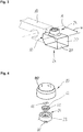
- Fig. 1 shows a handlebar end 20 with a base 22 which is disposed on a trailing arm 10 via a lower portion 26.
- the lower portion 26 is for this purpose partially formed as a bearing surface 28 and arranged substantially opposite an upper portion 25.
- the upper portion 25 includes a cylindrical portion 23 having an access area 24. Between the upper portion 25 and the lower portion 26 extends a distance a.
- the trailing arm 10 is disposed about a pivot point D in a vehicle frame / chassis 90. Not shown is an axle tube, which extends along the axial direction A and would be arranged according to the trailing arm 10.
- a rear portion 27 measures a length l.
- the main body 22 has a width b and is substantially parallelepiped-shaped, wherein a working volume formed by the main body 22 is arranged substantially below the access area 24.
- Fig. 2 shows a similar configuration as Fig. 1 , but here is a bearing surface 28, which also serves to be arranged on a trailing arm 10, offset by an offset x relative to a lower portion 26 arranged. Between an upper portion 25 and a lower portion 26, a distance a extends.
- An air spring system 80 which includes a bellows 80 'is disposed on the upper portion 25 and an access area (obscured by the configuration of the bellows 80').
- a main body 22 includes a front Section 30, via which at least partially also an arrangement on the trailing arm 10 takes place.
- Fig. 3 shows a further embodiment of a handlebar end 20, comprising an access area 24 and a substantially opposite lower portion 26.
- the handlebar end 20 is disposed and fixed, for example by welding, only via a front portion 30 on a trailing arm 10.
- a protrusion u which is dimensioned between a center of an axle tube, indicated here by the axial direction A, and a rear section 27.
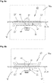
- Fig. 4 1 shows an embodiment of a valve unit 60 having an upper valve flap 64 'and a lower valve flap 64 "and a clamping plate 61 which is arranged in a cylindrical section 23.
- the clamping plate 61 comprises a plurality of valve openings 62.
- the valve unit 61 forms an access area 24
- a bellows 80 'of an air spring system 80 is disposed on the cylindrical portion 23.
- Fig. 5a shows a valve unit 60 in a plan view. You can see a clamping plate 61, in which an upper valve flap 64 'is inserted. A lower valve flap 64 "can be seen through the valve openings 62.
- the clamping plate 61 has a plurality of openings on its circumference for attachment, for example to a main body of a handlebar end Fig. 5b explained.
- Fig. 5b shows the section AA Fig. 5a , Clearly visible is the arrangement of guide pins 67 in the clamping plate 61. These prevent rotation of the valve flaps 64 ', 64 ".A spring element 66 in the form of a helical spring is arranged around a guide element 65.
- the guide element 65 is formed by a screw which partially has no thread, whereby the lower valve flap 64 "on the guide member 65 can slide.
- the spring element 66 is supported between a support element 68 and a washer 68 and the lower Valve flap 64 "off., As a result, both valve flaps 64 ', 64" are biased against each other.
- Fig. 6a shows a valve unit 60 in a side view.
- a clamping plate 61 is arranged in a base body 22 or in an upper portion 25.
- the two valve flaps 64 'and 64 are arranged on a guide element 65 and are biased by a biasing or spring element 66.
- Guide pins 67 can also be seen Fig. 6a 1, a compression is shown in which a volume of the (air) Federbalgs V 80 is reduced, so that against the force of the spring member 66, the lower valve flap 64 "is opened and air flows from a volume V 80 to a working volume V. Dies ist indicated by the arrows.
- Fig. 6b shows the off Fig. 6a known embodiment, but at a time when the volume of the bellows V 80 increases again.
- the upper valve flap 64 By expanding the spring bellows, the upper valve flap 64 'opens and air flows back from the working volume V into the volume V 80 (see also the arrows here). This, too, takes place against the bias of the spring element 66.
Landscapes
- Engineering & Computer Science (AREA)
- Mechanical Engineering (AREA)
- General Engineering & Computer Science (AREA)
- Vehicle Body Suspensions (AREA)
- Axle Suspensions And Sidecars For Cycles (AREA)
Description
- Die vorliegende Erfindung betrifft ein Lenkerende für einen Längslenker, insbesondere für Nutzfahrzeuge, einen Längslenker sowie eine Ventileinheit.
- Längslenker werden bei Radaufhängungen von Kraftfahrzeugen verwendet und sind überwiegend in Längsrichtung des Fahrzeugs orientiert. Sie dienen der Abstützung von Bremskräften und Bremsreaktionsmomenten. Daneben sind sie durch ihre bewegliche Lagerung die maßgeblichen Teile eines Federungssystems. Zum Bereitstellen der Federwirkung werden im Nutzfahrzeugbereich vor allem Luftfedersysteme verwendet. Hierbei werden Federbälge, insbesondere aus Gummi, mit einem luftdicht abgeschlossenen Arbeitsvolumen verbunden und stellen so die Federwirkung bereit. Der Nachteil dabei ist, dass das Arbeitsvolumen einen großen Bauraum beansprucht, welcher im Bereich des Fahrwerks nicht zur Verfügung steht.
- Die
WO 2013/165238 A1 befasst sich mit einer Luftfeder, umfassend eine Montageplatte, ein flexibles röhrenförmiges Element, einen Kolben und zumindest ein Ventil, wobei das Ventil dazu ausgelegt ist, eine fluidleitende Verbindung einer Hauptkammer mit einer Reservekammer zu etablieren. - Die
WO 2012/145451 A1 offenbart eine Luftfederanordnung für ein Fahrzeug mit einer variablen Federrate. - Die
WO 2012/087917 A1 befasst sich mit Kolbenanordnungen, welche eine integrale Kolbenkammer aufweisen, wobei der Kolben an einem Strukturelement festlegbar ist und die Kolbenkammer zumindest zwei Seiten des Strukturelements umschließen. - Die
EP 1 106 880 A2 offenbart ein Luftventil mit einem Gehäuseoberteil und einem Gehäuseunterteil, wobei das Gehäuseoberteil eine Abluftöffnung und das Gehäuseunterteil eine Zuluftöffnung aufweisen. - Die
US 4 858 949 A befasst sich mit einem Leichtbaulängslenker mit einer Luftfederanordnung bestehend aus einem festgelegten Becher und einem beweglichen Kolben. - Die
DE 14 30 075 A1 betrifft ein Massenfedersystem mit Hauptbehälter und Nachschaltbehälter, wobei in einem die beiden Behälter verbindenden Durchlass ein Dämpfer vorgesehen ist. - Es ist daher eine Aufgabe der vorliegenden Erfindung, ein Lenkerende für einen Längslenker, einen Längslenker sowie eine Ventileinheit anzugeben, welche ein kompaktes und kostengünstiges Luftfedersystem, insbesondere für Nutzfahrzeuganwendungen, ermöglichen.
- Diese Aufgabe wird durch ein Lenkerende gemäß Anspruch 1 sowie durch einen Längslenker gemäß Anspruch 11 gelöst. Weitere Vorteile und Merkmale der Erfindung ergeben sich aus den Unteransprüchen sowie der Beschreibung und den beigefügten Figuren.
- Erfindungsgemäß umfasst ein Lenkerende für einen Längslenker, insbesondere für Nutzfahrzeuge, einen Grundkörper, der ein Arbeitsvolumen für ein Luftfedersystem ausbildet, wobei der Grundkörper einen Zugangsbereich aufweist, welcher ausgelegt ist, einen Zugang in das Arbeitsvolumen bereitzustellen, dadurch gekennzeichnet, dass ein Großteil des Arbeitsvolumens im Wesentlichen unmittelbar unterhalb des Zugangsbereichs ausgebildet ist. Ein Luftfedersystem ist ein Federungssystem, das die Kompressibilität von Gasen, genauer der Luft, ausnutzt. Vorteile des Luftfedersystems sind die ruhige und komfortable Fahrweise und die variable Fahrzeughöhe. Das Luftfedersystem dient sowohl zur Abfederung zweier zueinander beweglicher Fahrzeugteile als auch zur Veränderung der Niveaulage des Fahrzeugs. Es kann also die Bodenfreiheit variiert werden. Die Federung erfolgt mittels Luft- bzw. Federbälgen, zweckmäßigerweise aus einem Kunststoffwerkstoff, insbesondere einem Gummiwerkstoff, in denen Druckluft beim Ein- und Ausfedern mit schwankendem Druck die Gegenkraft zu den fahrdynamischen Kräften am jeweiligen Rad oder der Achse bildet. Das Lenkerende ist dasjenige Bauteil, welches zur Anordnung/Befestigung des Luftfedersystems und insbesondere des (Luft-)Federbalgs dient, nämlich insbesondere dadurch, dass es den Zugangsbereich aufweist. Hierzu weist das Lenkerende zweckmäßigerweise einen oberen Abschnitt auf, welcher den vorgenannten Zugangsbereich aufweist bzw. umfasst. In einer Ausführungsform ist der obere Abschnitt eine im Wesentlichen glatte/plane/ebene Oberfläche, welche den Zugangsbereich aufweist. Der Zugangsbereich ist nach einer Ausführungsform als Loch, Öffnung oder allgemein als Durchbruch ausgebildet, der einen Zugang in das Innere des Lenkerendes bereitstellt, wobei der Zugangs so gestaltet ist, dass Luft in das Arbeitsvolumen hinein- bzw. hinausströmen kann. In einer Ausführungsform umfasst der obere Abschnitt einen zylinderförmigen Abschnitt, der insbesondere einen Abrollkolben für einen Luftbalg ausbilden kann. Der zylinderförmige Abschnitt dient zweckmäßigerweise der Anordnung/Befestigung des Federbalgs und weist den Zugangsbereich auf. Anders ausgedrückt ist der Zugangsbereich innerhalb des zylindrischen Abschnitts, in einer Ausführungsform beispielsweise im Wesentlichen mittig, angeordnet. Der Begriff "Lenkerende" bezieht sich darauf, dass das Lenkerende, oder auch "tail end", der Teil des Längslenkers ist, welcher in Fahrtrichtung gesehen zuhinterst angeordnet ist. Ein vorderes oder gegenüberliegendes Ende des Längslenkers weist zweckmäßigerweise einen Drehpunkt auf, über welchen die bewegliche Anordnung des Längslenkers an einem Fahrzeugrahmen erfolgt. Zudem weist der Längslenker auch noch einen Anordnungsabschnitt für ein Achsrohr auf. Vorliegend wird der Ausdruck Längslenker auch für einen Längslenker verwendet, der ggf. noch kein Lenkerende aufweist und daher streng genommen vielleicht kein "vollständiger" Längslenker ist. Aus dem Stand der Technik ist es teilweise bekannt, die Volumina angrenzender Fahrzeugteile in irgendeiner Art und Weise als Ausgleichsvolumina oder dergleichen für das Luftfedersystem zu verwenden. Zweckmäßigerweise umfasst vorliegend das Lenkerende den Grundkörper, welcher das Arbeitsvolumen unmittelbar selbst ausbildet, wobei hier das "Arbeitsvolumen" auch etwaige Zusatzvolumina etc. miteinschließt. Vorteilhafterweise wird damit eine kompakte Baueinheit erreicht, welche jegliche Verbindungselement wie Schläuche, Kupplungen, Dichtungen etc. einspart, wodurch ein einfaches und kostengünstiges System/Produkt realisierbar ist. In einer Ausführungsform handelt es sich bei dem Arbeitsvolumen um ein geschlossenes Volumen, welches im Wesentlichen unmittelbar unterhalb des Zugangsbereichs ausgebildet ist. Dies bedeutet, dass, wie eingangs erwähnt, ein Großteil des Arbeitsvolumens unterhalb des Zugangsbereichs oder unterhalb des unteren Abschnitts ausgebildet ist. Dabei bedeutet der Ausdruck "Großteil", das direkt unmittelbar unterhalb des Zugangsbereichs mehr als 50 %, insbesondere mehr als 60, 70 oder 80 % des Arbeitsvolumens angeordnet sind. In einer Ausführungsform umfasst das Arbeitsvolumen beispielsweise ca. 10 bis 100 l, ggf. 20 bis 80 l oder bevorzugt auch zwischen 30 und 60 l. Ein Verhältnis zwischen einem Volumen eines Luftfederbalgs zum Arbeitsvolumen liegt zweckmäßigerweise in einem Bereich von etwa 0,91 bis 0,34, bevorzugt in einem Bereich von etwa 0,67 bis 0,5. In einer Ausführungsform wird das Arbeitsvolumen nach oben durch den oberen Abschnitt begrenzt, was beutet, dass das Arbeitsvolumen keinen Bauraum oberhalb des bevorzugt ebenen oberen Abschnitts aufweist.
- Erfindungsgemäß ist der Grundkörper ein geschlossener Hohlkörper, wobei der Hohlkörper zweckmäßigerweise den Zugangsbereich aufweist. Bei dem geschlossenen Hohlkörper kann es sich in einem nicht erfindungsgemäßen Beispiel um eine Schweißkonstruktion aus Metall, insbesondere Stahl oder Aluminium, handeln. Erfindungsgemäß handelt es sich bei dem Hohlkörper um ein mittels Innenhochdruck umgeformtes Bauteil. Alternativ kann auch die zumindest teilweise Verwendung von Faserverbundwerkstoffen, wie glasfaser- oder kohlefaserverstärkten Werkstoffen, vorgesehen sein, was die mögliche Formenvielfalt zusätzlich erhöht. Wie bereits erwähnt, ist der Zugangsbereich eine Öffnung, welche die unterschiedlichsten Geometrien und Abmessungen aufweisen kann und sich in der Regel nach Art und Größe des verwendeten Luftfedersystems bzw. des verwendeten Federbalgs richtet. Insbesondere kann der Zugangsbereich beispielsweise auch eine Vielzahl von Öffnungen, beispielsweise zwei, drei, vier, fünf, sechs und mehr aufweisen. Das "geschlossen" ist dahingehend zu verstehen, dass der Grundkörper gerade keine weiteren Anschlüsse für etwaige Zusatzvolumina oder Ausgleichsvolumina aufweist, sondern diese Funktionen aufgrund seiner Dimensionierung und Gestaltung selbst wahrnehmen kann.
- In einer Ausführungsform weist der Grundkörper gegenüber dem Zugangsbereich bzw. gegenüber dem oberen Abschnitt einen unteren Abschnitt auf, wobei der untere Abschnitt mehr als 5 cm, bevorzugt mehr als 8 cm und insbesondere bevorzugt mehr als 10 cm vom Zugangsbereich bzw. vom oberen Abschnitt beabstandet ist. In einer Ausführungsform ist der untere Abschnitt durch eine im Wesentlichen ebene untere Fläche gebildet, welche sich im Wesentlichen parallel zu einer Fahrbahnebene erstreckt. Selbstverständlich kann die untere Fläche auch nach vorne, nach hinten oder zu den Seiten hin geneigt sein. Entscheidend ist, dass die untere Fläche durch ihren Abstand vom Zugangsbereich bzw. vom oberen Abschnitt ein ausreichend großes Arbeitsvolumen bereitstellt. In einer Ausführungsform sind der obere Abschnitt und der untere Abschnitt etwa parallel zueinander ausgerichtet und weisen einen Abstand von etwa 10 bis 50 cm, bevorzugt von etwa 13 bis 30 cm auf. Nach hinten, also entgegen der Fahrtrichtung, ist der Grundkörper durch einen hinteren Abschnitt begrenzt, welcher in einer Ausführungsform im Wesentlichen senkrecht zum oberen und unteren Abschnitt orientiert ist. Nach vorne ist der Grundkörper durch einen vorderen Abschnitt begrenzt. In einer Ausführungsform ist der vordere Abschnitt zumindest bereichsweise parallel zum hinteren Abschnitt ausgebildet bzw. orientiert. Ein unterer Bereich des vorderen Abschnitts kann nach einer Ausführungsform schräg bzw. geneigt sein. In einer Ausführungsform hat der Grundkörper eine etwa quaderförmige Gestaltung. Eine Länge des Grundkörpers des Lenkerendes beträgt in einer Ausführungsform etwa 30 bis 60 cm, bevorzugt etwa 40 bis 50 cm. Zweckmäßigerweise ist ein Überstand des Lenkerendes, welcher sich von einer Achsrohrmitte zum hinteren Abschnitt bemisst (im Wesentlichen parallel zu einer Fahrbahnebne bzw. entlang einer Längsrichtung des Längslenkers) kleiner als 90 cm. In einer Ausführungsform ist der Überstand z. B. zwischen 30 und 90 cm, bevorzugt zwischen 40 und 60 cm lang. Eine Breite des Grundkörpers beträgt in einer Ausführungsform etwa 20 bis 50 cm, bevorzugt etwa 25 bis 40 cm. Die Höhe bzw. der Abstand zwischen dem oberen und dem unteren Abschnitt wurde bereits erwähnt. In einer Ausführungsform beträgt eine Wandstärke etwa 3 bis 7 mm, bevorzugt etwa 4 bis 5 mm.
- Obwohl es sich um einen Hohlkörper handelt, kann der Grundkörper in einer Ausführungsform auch im Inneren eine Versteifung in Form von Rippen, Streben oder allgemein von Verstärkungselementen aufweisen, welche ausgelegt sind, die Festigkeit bzw. Steifigkeit des Grundkörpers zu erhöhen. So wirken auf diesen sowohl im Inneren die Gaskräfte als auch von außen die Kräfte, die durch den Federbalg eingebracht werden, so dass eine stabile Konstruktion unabdingbar ist.
- In einer Ausführungsform umfasst der untere Abschnitt eine Auflagefläche, die zum Anordnen und Befestigen des Lenkerendes an einen Längslenker ausgelegt ist. In einer Ausführungsform ist die Auflagefläche in Richtung des Zugangsbereichs versetzt angeordnet, so dass der untere Abschnitt keine gerade Fläche aufweist. In einer Ausführungsform ist die Auflagefläche etwa 5 bis 20 cm, bevorzugt etwa 8 bis 15 cm, um einen Abstand in Richtung des Zugangsbereichs bzw. in Richtung des oberen Abschnitts versetzt. Eine Breite der Auflagefläche beträgt in einer Ausführungsform etwa 5 bis 20 cm, bevorzugt etwa 8 bis 15 cm. Der untere Abschnitt kann aber auch selbst die Funktion der Auflagefläche erfüllen. Grundsätzlich ist die Auflagefläche derart ausgelegt, dass sie zur Anordnung bzw. zur Montage an einen Längslenker ausgebildet bzw. ausgelegt ist. Die Verbindung mit dem Längslenker kann über eine form- und/oder kraftschlüssige oder auch über eine stoffschlüssige Verbindung wie beispielsweise Schweißen oder Kleben erfolgen. Für die form- und/oder kraftschlüssige Verbindung können entsprechende Nieten, Bolzen und dergleichen verwendet werden.
- Wie bereits erwähnt, weist der Grundkörper auch einen vorderen Abschnitt auf, welcher ebenfalls die Funktion einer Auflage- oder Anordnungsfläche bereitstellen kann, mit anderen Worten also zum Anordnen des Lenkerendes an einen Längslenker ausgelegt ist. In einer Ausführungsform handelt es sich dabei um eine im Wesentlichen horizontale Außenwand, welche derart ausgelegt ist, dass sie an einen Längslenker angeordnet und befestigt, beispielsweise verschweißt werden kann. Die Außenwand kann dabei glatt oder auch strukturiert sein, um ggf. auch einen Formschluss mit dem Längslenker zu ermöglichen. In einer Ausführungsform ist das Lenkerende über den unteren Abschnitt bzw. die Auflagefläche und den vorderen Abschnitt an einem Längslenkers angeordnet und befestigt. In einer anderen Ausführungsform ist das Lenkerende nur mittels des vorderen Abschnitts an dem Längslenker befestigt, beispielsweise über eine form- und/oder eine kraft- und/oder eine stoffschlüssige Verbindung.
- In einer Ausführungsform umfasst das Lenkerende eine Ventileinheit, welche eine Klemmplatte umfasst, wobei die Klemmplatte eine Vielzahl von Ventilöffnungen, insbesondere vier Ventilöffnungen, aufweist. In einer Ausführungsform ist im Zugangsbereich bzw. im Übergangsbereich zwischen dem Volumen des Federbalgs und dem Arbeitsvolumen die Ventileinheit vorgesehen, welche entsprechend der Druckverhältnisse in den beiden Volumina öffnet und schließt. Gemäß einer Ausführungsform ist die Klemmplatte im oder am oberen Abschnitt des Grundkörpers bzw. im oder am zylinderförmigen Abschnitt angeordnet. In einer Ausführungsform mit vier Ventilöffnungen weisen jeweils zwei Ventilöffnungen einen (maximalen) Querschnitt von etwa 400 bis 1500 mm2, bevorzugt von etwa 500 bis 1200 mm2, besonders bevorzugt von etwa 600 bis 1000 mm2 auf. Grundsätzlich ist der Querschnitt abhängig von dem anliegenden Druckunterschied und der (auftretenden) Frequenz. Üblich ist in diesem Zusammenhang die Einheit mm2/bar, wobei typische Werte in einem Bereich von etwa 450 bis 650 mm2/bar liegen, bevorzugt bei etwa 480 bis 620 mm2/bar (10 Hz ca. 1,2 bar, 5 Hz ca. 0,3 bar, 15 Hz ca. 0,4 bar). Bevorzugte Querschnittswerte liegen demnach in einem Bereich von etwa 0 bis 800 mm2 oder, wenn ein Bypass vorhanden ist, in einem Bereich von etwa 20 bis 800 mm2. Durch die Reibung in der Ventileinheit kann eine Dämpfung durch das Luftfedersystem erzeugt werden. Dies kann die Einsparung eines (Stoß-) Dämpfers ermöglichen. In einer Ausführungsform ist die Klemmplatte rund, insbesondere kreisrund, und weist einen Durchmesser von etwa 70 bis 120 mm auf, bevorzugt von etwa 80 bis 110 mm, und ganz besonders bevorzugt von etwa 90 bis 100 mm, beispielsweise 94 mm. In einer Ausführungsform weist die Klammplatte eine Wandstärke von etwa 2 bis 7 mm, bevorzugt von etwa 3 bis 6 mm und ganz besonders bevorzugt von etwa 4 bis 5 mm, beispielsweise 4,6 mm, auf. Die Klemmplatte ist in einer Ausführungsform aus Metall oder aus einem Kunststoff gefertigt. In einer Ausführungsform sind ein oder mehrere Führungsstifte in der Klemmplatte derart angeordnet, dass die Bewegung der nachfolgend beschriebenen Ventilklappen durch die Führungsstifte geführt wird. Insbesondere verhindern die Führungsstifte eine Rotation der Ventilklappen zueinander. Die Führungsstifte können beispielsweise als Zylinderstifte ausgebildet sein, die eine Länge von etwa 15 mm und einen Durchmesser von etwa 2 mm aufweisen.
- In einer Ausführungsform umfasst die Ventileinheit eine obere Ventilklappe und eine untere Ventilklappe, wobei die Ventilklappen derart angeordnet sind, dass jeweils unterschiedliche Ventilöffnungen geöffnet und geschlossen werden können. Die obere Ventilklappe ist zweckmäßigerweise oberhalb der Klemmplatte angeordnet, die untere Ventilklappe zweckmäßigerweise unterhalb der Klemmplatte. Zweckmäßigerweise weisen die Ventilklappen entsprechende Abschnitte/Bereiche auf, die ausgelegt sind, die Ventilöffnungen der Ventileinheit bzw. der Klemmplatte abzudecken. Die gegenüberliegenden Ventilklappen sind gemäß einer Ausführungsform so versetzt angeordnet, beispielsweise um 90° versetzt, dass sie jeweils unterschiedliche Ventilöffnungen abdecken und freigeben können.
- Zweckmäßigerweise umfasst die Ventileinheit ein Führungselement, welche derart ausgelegt ist, dass sich die Ventilklappen entlang des Führungselements bewegen können. Gemäß einer Ausführungsform handelt es sich bei dem Führungselement um einen Stift, Bolzen, Steg oder auch um eine Schraube, die zumindest bereichsweise kein Gewinde aufweist. Ein Querschnitt des Führungselements ist also bevorzugt rund, insbesondere kreisrund. Ein ovaler oder eckiger Querschnitt kann ebenfalls zweckmäßig sein, da dadurch evtl. auf die zuvor genannten Führungsstifte verzichtet werden kann. Ein Durchmesser eines runden Querschnitts liegt gemäß einer Ausführungsform in einem Bereich von etwa 4 bis 8 mm, bevorzugt in einem Bereich von etwa 5 bis 7 mm, beispielsweise 6 mm. Das Führungselement ist in einer entsprechenden Öffnung/Aussparung der Klemmplatte, zweckmäßigerweise mittig, angeordnet.
- In einer Grundstellung liegen die Ventilklappen an der Klemmplatte derart an, dass die Ventilöffnungen verschlossen sind.
- Hierzu umfasst die Ventileinheit zweckmäßigerweise ein Vorspann- oder Federelement, welches die Ventilklappen in Richtung der Klemmplatte vorspannt oder mit einer (Feder-) Kraft beaufschlägt. Zweckmäßigerweise ist das Federelement derart zwischen einer der Ventilklappen und einem Abstützelement angeordnet, dass bei einer Bewegung der unteren Ventilklappe nach unten und bei einer Bewegung der oberen Ventilklappe nach oben eine Komprimierung des Federelements stattfindet. Nach einer Ausführungsform ist z. B. das Federelement zwischen der unteren Ventilklappe und dem Abstützelement angeordnet, wobei das weitere Element eine Scheibe ist, die sich an einer als Führungselement ausgebildeten Schraube (beispielsweise über eine dort angeordnete Mutter) abstützt. Vorteilhafterweise ist die Anordnung so ausgebildet, dass die Ventilklappen bei Verwendung nur eines Federelements gegeneinander verspannt sind. Wird der Federbalg belastet, wird der Druck im Volumen des Federbalgs durch dessen Komprimierung erhöht. Der Überdruck bzw. die Druckdifferenz zwischen dem Druck im Arbeitsvolumen und dem Druck im Federbalg bewirkt gegen die Kraft des Federelements ein Bewegen der unteren Ventilklappe gegen die Federkraft nach unten. Das Expandieren des Federbalgs (beim Ausfedern) führt zu einem Differenzdruck zwischen dem Volumen des Federbalgs und dem Arbeitsvolumen derart, dass im Arbeitsvolumen ein höherer Druck herrscht als im Volumen des Federbalgs. Diese Druckdifferenz bewirkt gegen die Kraft des Federelements ein Verlagern der oberen Ventilklappe nach oben. Es gibt also eine obere Stellung, in der die obere Ventilklappe in einer oberen Position ist und eine untere Stellung, in der die untere Ventilklappe in einer unteren Position ist. Die Bewegung der Ventilklappen erfolgt dabei nicht allein nur durch das Anliegen eines Druckverhältnisses sondern auch direkt durch des Gasdruck, der auf die Flächen der Ventilklappen wirkt, die durch die Klemmplatte bzw. die jeweils andere Ventilklappe nicht verdeckt sind. Grundsätzlich kann es sich bei dem Vorspann- oder Federelement um ein Elastomerelement oder um eine Schraubenfeder, insbesondere um eine zylindrische Schrauben-Druckfeder handeln, beispielsweise gemäß DIN 2098 mit den Dimensionen 1x8x13. Zweckmäßigerweise ist innerhalb des Federelements das Führungselement positioniert.
- In einer Ausführungsform sind die Ventilklappen zweiblättrig ausgebildet, so dass sie jeweils zwei Öffnungen der Ventileinheit schließen können. Die Form der Ventilklappen ist zweckmäßigerweise auf die Form der Ventilöffnungen angepasst. Die Ventilöffnungen können rund, eckig, schlitzartig, dreieckig, etc. ausgebildet sein, wobei hinsichtlich deren Formgebung keine Grenzen gesetzt sind. Die bereits genannten Querschnitte der Ventilöffnungen können gleich oder auch unterschiedlich groß ausgeführt sein, wodurch die Dämpfungscharakteristik beeinflusst werden kann. Ein Durchmesser der Ventilklappen beträgt in einer Ausführungsform etwa 3 bis 10 cm, bevorzugt etwa 4 bis 8 cm. Zweckmäßigerweise weisen die Ventilklappen entsprechende Führungsöffnungen beispielsweise in Form von Löchern oder Bohrungen zur Aufnahme/Anordnung der zuvor genannte Führungsstifte auf.
- Gemäß einer alternativen Ausführungsform kann auch auf die Klemmplatte verzichtet werden. In diesem Fall weist der Zugangsbereich die Ventilöffnungen auf und stellt die Eigenschaften der Klemmplatte bereit.
Die Erfindung umfasst auch einen Längslenker, insbesondere für Nutzfahrzeuge, der ein erfindungsgemäßes Lenkerende umfasst. Ein hinterer Teil des Längslenkers ist also mit Vorteil als das erfindungsgemäße Lenkerende ausgebildet. - In einer Ausführungsform können der Längslenker und das Lenkerende einteilig ausgebildet sein. In einer Ausführungsform ist damit eine einteilige Struktur im Wortsinn gemeint, also gerade keine form- und/oder kraftschlüssige bzw. auch stoffschlüssige Verbindung zwischen einem Längslenker (-vorderteil) und einem Lenkerende sondern die Ausbildung des Längslenkers als ein Teil, wobei der hintere Teil als das erfindungsgemäße Lenkerende ausgebildet ist. Das Merkmal betreffend die "Einteiligkeit" ist nach einer Ausführungsform auch dahingehend auszulegen, dass zumindest ein Bereich, umfassend das Lenkerende und einen Mittelteil des Längslenkers, einteilig oder aus einem Stück ausgebildet ist.
- Weiter umfasst die Erfindung auch eine erfindungsgemäße Ventileinheit. Es versteht sich, dass die in Zusammenhang mit dem erfindungsgemäßen Lenkerende erwähnten Vorteile und Merkmale auch für den erfindungsgemäßen Längslenker und die erfindungsgemäße Ventileinheit gelten, wie auch umgekehrt und untereinander.
- Weitere Vorteile und Merkmale ergeben sich mit Bezug auf die beigefügten Figuren aus der nachfolgenden Beschreibung bevorzugter Ausführungsformen des erfindungsgemäßen Lenkerendes, des erfindungsgemäßen Längslenkers sowie der erfindungsgemäßen Ventileinheit. Einzelne Merkmale der einzelnen Ausführungsformen können dabei im Rahmen der Erfindung miteinander kombiniert werden.
- Es zeigen:
- Fig. 1:
- eine Ausführungsform eines Lenkerendes, angeordnet an einem Längslenker;
- Fig. 2:
- eine Ausführungsform eines Lenkerendes, angeordnet an einem Längslenker;
- Fig. 3:
- eine Ausführungsform eines Lenkerendes, angeordnet an einem Längslenker;
- Fig. 4:
- eine Ausführungsform einer Ventileinheit;
- Fig. 5a:
- eine Ausführungsform einer Ventileinheit in einer Draufsicht;
- Fig. 5b:
- den in
Fig. 5a gekennzeichneten Schnitt A-A; - Fig. 6a:
- eine Ausführungsform einer Ventileinheit in einer Seitenansicht;
- Fig. 6b:
- die aus
Fig. 6a bekannte Ausführungsform der Ventileinheit, bei welcher die Ventilklappen in einer anderen Position sind. -
Fig. 1 zeigt ein Lenkerende 20 mit einem Grundkörper 22, der an einem Längslenker 10 über einen unteren Abschnitt 26 angeordnet ist. Der untere Abschnitt 26 ist hierzu teilweise als Auflagefläche 28 ausgebildet und im Wesentlichen gegenüberliegend einem oberen Abschnitt 25 angeordnet. Der obere Abschnitt 25 umfasst einen zylinderförmiger Abschnitt 23, welcher einen Zugangsbereich 24 aufweist. Zwischen dem oberen Abschnitt 25 und dem unteren Abschnitt 26 erstreckt sich ein Abstand a. Der Längslenker 10 ist über einen Drehpunkt D in einem Fahrzeugrahmen/Chassis 90 angeordnet. Nicht eingezeichnet ist ein Achsrohr, welches sich entlang der Achsrichtung A erstreckt und im Längslenker 10 entsprechend angeordnet wäre. Zwischen einem vorderen Abschnitt 30, über welchen ebenfalls eine zumindest teilweise Anordnung/Befestigung an dem Längslenker 10 erfolgen kann, und einem hinteren Abschnitt 27 bemisst sich eine Länge l. Der Grundkörper 22 weist eine Breite b auf und ist im Wesentlichen quaderförmig geformt, wobei ein durch den Grundkörper 22 ausgebildetes Arbeitsvolumen im Wesentlichen unterhalb des Zugangsbereichs 24 angeordnet ist. -
Fig. 2 zeigt eine ähnliche Konfiguration wieFig. 1 , allerdings ist hier eine Auflagefläche 28, welche ebenfalls zur Anordnung an einem Längslenker 10 dient, um einen Versatz x gegenüber einem unteren Abschnitt 26 versetzt angeordnet. Zwischen einem oberen Abschnitt 25 und einem unteren Abschnitt 26 erstreckt sich ein Abstand a. Ein Luftfedersystem 80, welches einen Federbalg 80' umfasst, ist auf dem oberen Abschnitt 25 bzw. einem Zugangsbereich (durch die Anordnung des Federbalgs 80' verdeckt) angeordnet. Ein Grundkörper 22 umfasst einen vorderen Abschnitt 30, über welchen zumindest bereichsweise ebenfalls eine Anordnung an dem Längslenker 10 erfolgt. -
Fig. 3 zeigt eine weitere Ausführungsform eines Lenkerendes 20, umfassend einen Zugangsbereich 24 und einen im Wesentlichen gegenüberliegenden unteren Abschnitt 26. In der hier gezeigten Ausführungsform ist das Lenkerende 20 lediglich über einen vorderen Abschnitt 30 an einem Längslenker 10 angeordnet und befestigt, beispielsweise verschweißt. Dargestellt ist in dieser Figur auch ein Überstand u, welcher sich zwischen einer Mitte eines Achsrohrs, vorliegend angedeutet durch die Achsrichtung A, und einem hinteren Abschnitt 27 bemisst. -
Fig. 4 zeigt eine Ausführungsform einer Ventileinheit 60 mit einer oberen Ventilklappe 64' und einer unteren Ventilklappe 64" sowie einer Klemmplatte 61, welche in einem zylinderförmigen Abschnitt 23 angeordnet ist. Die Klemmplatte 61 umfasst mehrere Ventilöffnungen 62. Die Ventileinheit 61 bildet einen Zugangsbereich 24 aus bzw. ist in diesem angeordnet. Ein Federbalg 80' eines Luftfedersystems 80 wird auf dem zylinderförmigen Abschnitt 23 angeordnet. -
Fig. 5a zeigt eine Ventileinheit 60 in einer Draufsicht. Zu sehen ist eine Klemmplatte 61, in der eine obere Ventilklappe 64' eingelegt ist. Durch die Ventilöffnungen 62 hindurch ist eine untere Ventilklappe 64" erkennbar. Die Klemmplatte 61 weist an ihrem Umfang mehrere Öffnungen zur Befestigung, beispielsweise an einem Grundkörper eines Lenkerendes, auf. Ein Schnitt A-A ist inFig. 5b erklärt. -
Fig. 5b zeigt den Schnitt A-A aufFig. 5a . Deutlich zu erkennen ist die Anordnung von Führungsstiften 67 in der Klemmplatte 61. Diese verhindern ein Rotieren der Ventilklappen 64', 64". Ein Federelement 66 in Form einer Schraubenfeder ist um ein Führungselement 65 angeordnet. Das Führungselement 65 ist durch eine Schraube gebildet, die bereichsweise kein Gewinde aufweist, wodurch die untere Ventilklappe 64" auf dem Führungselement 65 gleiten kann. Das Federelement 66 stützt sich zwischen einem Abstützelement 68 bzw. einer Scheibe 68 und der unteren Ventilklappe 64" ab. Dadurch sind beide Ventilklappen 64', 64" gegeneinander vorgespannt. -
Fig. 6a zeigt eine Ventileinheit 60 in einer Seitenansicht. Eine Klemmplatte 61 ist in einem Grundkörper 22 oder in einem oberen Abschnitt 25 angeordnet. Die beiden Ventilklappen 64' und 64" sind an einem Führungselement 65 angeordnet und über ein Vorspann- oder Federelement 66 vorgespannt. Zu erkennen sind auch Führungsstifte 67. InFig. 6a ist ein Einfedern dargestellt, bei welchem ein Volumen des (Luft-)Federbalgs V80 verkleinert wird, so dass gegen die Kraft des Federelements 66 die untere Ventilklappe 64" geöffnet wird und Luft von einem Volumen V80 zu einem Arbeitsvolumen V strömt. Dies ist durch die Pfeile angedeutet. -
Fig. 6b zeigt die ausFig. 6a bekannte Ausführungsform, allerdings zu einem Zeitpunkt, wenn sich das Volumen des Federbalgs V80 wieder vergrößert. Durch das Expandieren des Federbalgs kommt es zu einem Öffnen der oberen Ventilklappe 64' und Luft strömt von dem Arbeitsvolumen V in das Volumen V80 zurück (siehe auch hier die Pfeile). Auch dies erfolgt gegen die Vorspannung des Federelements 66. -
- 10
- Längslenker
- 20
- Lenkerende
- 22
- Grundkörper
- 23
- zylinderförmiger Abschnitt
- 24
- Zugangsbereich
- 25
- oberer Abschnitt
- 26
- unterer Abschnitt
- 27
- hinterer Abschnitt
- 28
- Auflagefläche
- 30
- vorderer Abschnitt
- 60
- Ventileinheit
- 61
- Klemmplatte
- 62
- Ventilöffnung(en)
- 64'
- obere Ventilklappe
- 64"
- untere Ventilklappe
- 65
- Führungselement
- 66
- Federelement, Schrauben-Druckfeder
- 67
- Führungsstift
- 68
- Abstützelement. Scheibe
- 80
- Luftfedersystem
- 80'
- (Luft-)Federbalg
- 90
- Fahrzeugrahmen/Chassis
- V
- Arbeitsvolumen
- V80
- Federbalgvolumen
- A
- Achsrichtung
- D
- Drehachse
- a
- Abstand/Höhe
- b
- Breite
- l
- Länge
- x
- Versatz
- u
- Überstand
Claims (12)
- Lenkerende (20) für einen Längslenker (10), insbesondere für Nutzfahrzeuge,
umfassend einen Grundkörper (22), der ein Arbeitsvolumen (V) für ein Luftfedersystem (80) ausbildet,
wobei der Grundkörper (22) einen Zugangsbereich (24) aufweist, welcher ausgelegt ist, einen Zugang in das Arbeitsvolumen (V) bereitzustellen, wobei ein Großteil des Arbeitsvolumens (V) im Wesentlichen unterhalb des Zugangsbereichs (24) ausgebildet ist,
wobei der Grundkörper ein geschlossener Holkörper ist, dadurch gekennzeichnet, dass
es sich bei dem Hohlkörper um ein mittels Innenhochdruck umgeformtes Bauteil handelt. - Lenkerende (20) nach Anspruch 1, wobei der Grundkörper (22) gegenüber dem Zugangsbereich (24) einen unteren Abschnitt aufweist (26), und wobei der untere Abschnitt (26) mehr als 5 cm, bevorzugt mehr als 8 cm, insbesondere bevorzugt mehr als 10 cm, vom Zugangsbereich (24) beabstandet ist.
- Lenkerende (20) nach Anspruch 2, wobei der untere Abschnitt (26) eine Auflagefläche (28) umfasst, die zum Anordnen des Lenkerendes (20) an einen Längslenker (10) ausgelegt ist.
- Lenkerende (20) nach einem der vorhergehenden Ansprüche wobei der Grundkörper (22) einen vorderen Abschnitt aufweist, welcher die Funktion einer Auflage- oder Anordnungsfläche (28) bereitstellt, welche vorzugsweise eine im Wesentlichen horizontale Außenwand ist, die derart ausgelegt ist, dass sie an einen Längslenker (10) anodenbar und befestigbar ist.
- Lenkerende (20) nach einem der vorhergehenden Ansprüche, umfassend eine Ventileinheit (60), welche vorzugsweise eine Klemmplatte (61) aufweist, und wobei die Ventileinheit, insbesondere die Klemmplatte (61), eine Vielzahl von Ventilöffnungen (62), insbesondere vier Ventilöffnungen (62), aufweist.
- Lenkerende (20) nach Anspruch 5,
wobei die Ventileinheit (60) eine obere Ventilklappe (64') und eine untere Ventilklappe (64") umfasst, und
wobei die Ventilklappen (64', 64") derart angeordnet sind, dass jeweils unterschiedliche Ventilöffnungen (62) geöffnet und geschlossen werden können. - Lenkerende (20) nach Anspruch 5 oder 6,
wobei die Ventileinheit (60) ein Führungselement umfasst, welches derart ausgelegt ist, dass sich Ventilklappen (64', 64") entlang des Führungselements bewegen können. - Lenkerende (20) nach einem der Ansprüche 6 - 7, wobei die Ventilklappen (64', 64") in einer Grundstellung an der Klemmplatte (61) derart anliegen, dass die Ventilöffnungen (62) verschlossen sind.
- Lenkerende (20) nach einem der Ansprüche 6 - 8, wobei die Ventileinheit (60) ein Federelement (61) umfasst, welches die Ventilklappen (64', 64") vorspannt.
- Lenkerende (20) nach einem der Ansprüche 6 - 9 wobei die Ventilklappen (64', 64") jeweils zweiblättrig ausgebildet sind.
- Längslenker (10), insbesondere für Nutzfahrzeuge,
umfassend ein Lenkerende (20) nach einem der vorhergehenden Ansprüche. - Längslenker (10) nach Anspruch 11, wobei der Längslenker (10) und das Lenkerende (20) einteilig ausgebildet sind.
Priority Applications (1)
| Application Number | Priority Date | Filing Date | Title |
|---|---|---|---|
| PL16782080T PL3365190T3 (pl) | 2015-10-19 | 2016-10-18 | Koniec wahacza |
Applications Claiming Priority (2)
| Application Number | Priority Date | Filing Date | Title |
|---|---|---|---|
| DE102015117757.9A DE102015117757B4 (de) | 2015-10-19 | 2015-10-19 | Lenkerende |
| PCT/EP2016/074964 WO2017067920A2 (de) | 2015-10-19 | 2016-10-18 | Lenkerende |
Publications (2)
| Publication Number | Publication Date |
|---|---|
| EP3365190A2 EP3365190A2 (de) | 2018-08-29 |
| EP3365190B1 true EP3365190B1 (de) | 2019-01-30 |
Family
ID=57138084
Family Applications (1)
| Application Number | Title | Priority Date | Filing Date |
|---|---|---|---|
| EP16782080.2A Active EP3365190B1 (de) | 2015-10-19 | 2016-10-18 | Lenkerende |
Country Status (8)
| Country | Link |
|---|---|
| US (1) | US20200254841A1 (de) |
| EP (1) | EP3365190B1 (de) |
| CN (1) | CN108349343A (de) |
| CA (1) | CA3002571C (de) |
| DE (1) | DE102015117757B4 (de) |
| ES (1) | ES2717270T3 (de) |
| PL (1) | PL3365190T3 (de) |
| WO (1) | WO2017067920A2 (de) |
Families Citing this family (2)
| Publication number | Priority date | Publication date | Assignee | Title |
|---|---|---|---|---|
| DE102020103762B4 (de) | 2020-02-13 | 2023-10-12 | Saf-Holland Gmbh | Lenkersystem |
| DE102024134831A1 (de) * | 2024-11-26 | 2026-05-28 | Saf-Holland Gmbh | Geklebtes Lenkerende, Fahrzeugachssystem und Verfahren zum Anbinden eines Lenkerendes |
Family Cites Families (13)
| Publication number | Priority date | Publication date | Assignee | Title |
|---|---|---|---|---|
| FR1337108A (fr) * | 1961-10-25 | 1963-09-06 | Bridgestone Tire Co Ltd | Amortisseur pneumatique |
| CA1097380A (en) * | 1977-12-20 | 1981-03-10 | William C. Pierce | Air spring assembly |
| DE19957683A1 (de) | 1999-12-01 | 2001-06-28 | Edwin Wahl | Luftventil |
| DE10314621B4 (de) * | 2003-04-01 | 2006-03-09 | Carl Freudenberg Kg | Pneumatische Feder-Dämpfer-Einheit |
| NL2000753C2 (nl) * | 2007-07-16 | 2009-01-19 | Terberg Specials B V | Achterwielophanging voor een voertuig en voertuig daarmee uitgerust. |
| US8997953B2 (en) * | 2007-08-30 | 2015-04-07 | Tenneco Automotive Operating Company Inc. | Shock absorber having a full displacement valve assembly |
| CN201240242Y (zh) * | 2008-07-29 | 2009-05-20 | 郭孔辉 | 感载变阻尼或可控感载变阻尼减震系统 |
| US8801016B2 (en) * | 2010-12-20 | 2014-08-12 | Firestone Industrial Products Company, Llc | Gas spring piston and gas spring assembly including same |
| US20130099459A1 (en) * | 2011-04-21 | 2013-04-25 | Dana Heavy Vehicle Systems Group, Llc | Air Suspension System Having A Variable Spring Rate |
| EP2844505B1 (de) | 2012-05-01 | 2019-05-08 | Thomas Josephus Johannes Meijlink | Luftfeder mit einem anti-vakuum system |
| CN103085622B (zh) * | 2013-01-25 | 2015-10-28 | 中国公路车辆机械有限公司 | 一种中小型客车独立空气悬架 |
| DE102013210142A1 (de) * | 2013-05-31 | 2014-12-04 | Saf-Holland Gmbh | Lenkereinheit |
| DE102013113577B4 (de) * | 2013-12-05 | 2022-10-06 | Saf-Holland Gmbh | Abrollkolben |
-
2015
- 2015-10-19 DE DE102015117757.9A patent/DE102015117757B4/de active Active
-
2016
- 2016-10-18 ES ES16782080T patent/ES2717270T3/es active Active
- 2016-10-18 CA CA3002571A patent/CA3002571C/en not_active Expired - Fee Related
- 2016-10-18 WO PCT/EP2016/074964 patent/WO2017067920A2/de not_active Ceased
- 2016-10-18 US US15/769,006 patent/US20200254841A1/en not_active Abandoned
- 2016-10-18 EP EP16782080.2A patent/EP3365190B1/de active Active
- 2016-10-18 PL PL16782080T patent/PL3365190T3/pl unknown
- 2016-10-18 CN CN201680066400.XA patent/CN108349343A/zh active Pending
Non-Patent Citations (1)
| Title |
|---|
| None * |
Also Published As
| Publication number | Publication date |
|---|---|
| CN108349343A (zh) | 2018-07-31 |
| ES2717270T3 (es) | 2019-06-20 |
| DE102015117757B4 (de) | 2024-06-06 |
| WO2017067920A2 (de) | 2017-04-27 |
| PL3365190T3 (pl) | 2019-07-31 |
| EP3365190A2 (de) | 2018-08-29 |
| DE102015117757A1 (de) | 2017-04-20 |
| US20200254841A1 (en) | 2020-08-13 |
| CA3002571C (en) | 2019-11-19 |
| WO2017067920A3 (de) | 2017-08-10 |
| CA3002571A1 (en) | 2017-04-27 |
Similar Documents
| Publication | Publication Date | Title |
|---|---|---|
| EP1693233B1 (de) | Luftfederbein mit zentrisch angeordnetem Dämpfer | |
| EP2552717B1 (de) | Verbindungsstrebe | |
| DE112012004165T5 (de) | Gasfeder- und Gasdämpferbaugruppe und Verfahren | |
| DE102008053886B4 (de) | Luftfeder-Längslenker-Anordnung und Achsaggregat für eine Fahrzeug-Achse | |
| EP2780181B1 (de) | Achseinheit für nutzfahrzeuge | |
| EP4699828A1 (de) | Lenkbare einzelradaufhängung mit zusätzlichem träger | |
| DE102006015671A1 (de) | Fahrzeug-Achskörper | |
| DE202017100162U1 (de) | Lenker in Schalenbauweise für eine Radaufhängung eines Fahrzeugs | |
| EP3041693B1 (de) | Verbundlenkerachse mit ein- und ausbaubarem stabilisator | |
| EP3044052B1 (de) | Stütze zur unterstützung und zum ausgleich eines positionsversatzes von einem geparkten sattelanhänger | |
| EP2780182B1 (de) | Starrachse mit luftfederung | |
| DE102015108484B4 (de) | Querblattfeder für ein Kraftfahrzeug sowie Achsanordnung mit einer Querblattfeder | |
| DE102015117757B4 (de) | Lenkerende | |
| DE102020105380A1 (de) | Lenkbare Einzelradaufhängung mit Federeinrichtung | |
| DE102010028400A1 (de) | Querlenker in Schalenbauweise | |
| EP1777085B1 (de) | Achsaufhängung für eine längslenkergeführte Fahrzeugachse | |
| DE10050067C2 (de) | Vorrichtung zum luftdichten Verschließen eines Hubraums einer Luftfeder bei gleichzeitiger kugelgelenkartiger Führung eines hydraulischen Stoßdämpfers in diesem Hubraum | |
| EP3829905B1 (de) | Lagervorrichtung zur lagerung eines achslenkers | |
| EP3768533B1 (de) | Luftfedersystem | |
| WO2021190893A1 (de) | Abrollkolben für eine luftfeder eines kraftfahrzeugs | |
| DE102015209351B4 (de) | Längslenker | |
| DE102016221964B4 (de) | Hinterradaufhängung, insbesondere Integral-Hinterradaufhängung mit Luftfeder für ein Fahrzeug | |
| DE102017218795A1 (de) | Achsaufhängung | |
| EP3515732B1 (de) | Luftfedersystem, fahrzeug mit luftfedersystem und verfahren zur montage eines luftfedersystems | |
| DE3107380C2 (de) | Schwenklager |
Legal Events
| Date | Code | Title | Description |
|---|---|---|---|
| STAA | Information on the status of an ep patent application or granted ep patent |
Free format text: STATUS: THE INTERNATIONAL PUBLICATION HAS BEEN MADE |
|
| PUAI | Public reference made under article 153(3) epc to a published international application that has entered the european phase |
Free format text: ORIGINAL CODE: 0009012 |
|
| STAA | Information on the status of an ep patent application or granted ep patent |
Free format text: STATUS: REQUEST FOR EXAMINATION WAS MADE |
|
| 17P | Request for examination filed |
Effective date: 20180425 |
|
| AK | Designated contracting states |
Kind code of ref document: A2 Designated state(s): AL AT BE BG CH CY CZ DE DK EE ES FI FR GB GR HR HU IE IS IT LI LT LU LV MC MK MT NL NO PL PT RO RS SE SI SK SM TR |
|
| AX | Request for extension of the european patent |
Extension state: BA ME |
|
| GRAP | Despatch of communication of intention to grant a patent |
Free format text: ORIGINAL CODE: EPIDOSNIGR1 |
|
| STAA | Information on the status of an ep patent application or granted ep patent |
Free format text: STATUS: GRANT OF PATENT IS INTENDED |
|
| INTG | Intention to grant announced |
Effective date: 20181005 |
|
| GRAS | Grant fee paid |
Free format text: ORIGINAL CODE: EPIDOSNIGR3 |
|
| GRAA | (expected) grant |
Free format text: ORIGINAL CODE: 0009210 |
|
| STAA | Information on the status of an ep patent application or granted ep patent |
Free format text: STATUS: THE PATENT HAS BEEN GRANTED |
|
| DAV | Request for validation of the european patent (deleted) | ||
| DAX | Request for extension of the european patent (deleted) | ||
| AK | Designated contracting states |
Kind code of ref document: B1 Designated state(s): AL AT BE BG CH CY CZ DE DK EE ES FI FR GB GR HR HU IE IS IT LI LT LU LV MC MK MT NL NO PL PT RO RS SE SI SK SM TR |
|
| REG | Reference to a national code |
Ref country code: GB Ref legal event code: FG4D Free format text: NOT ENGLISH |
|
| REG | Reference to a national code |
Ref country code: CH Ref legal event code: EP |
|
| REG | Reference to a national code |
Ref country code: AT Ref legal event code: REF Ref document number: 1092955 Country of ref document: AT Kind code of ref document: T Effective date: 20190215 |
|
| REG | Reference to a national code |
Ref country code: IE Ref legal event code: FG4D Free format text: LANGUAGE OF EP DOCUMENT: GERMAN |
|
| REG | Reference to a national code |
Ref country code: DE Ref legal event code: R096 Ref document number: 502016003316 Country of ref document: DE |
|
| REG | Reference to a national code |
Ref country code: NL Ref legal event code: FP |
|
| REG | Reference to a national code |
Ref country code: LT Ref legal event code: MG4D |
|
| REG | Reference to a national code |
Ref country code: ES Ref legal event code: FG2A Ref document number: 2717270 Country of ref document: ES Kind code of ref document: T3 Effective date: 20190620 |
|
| PG25 | Lapsed in a contracting state [announced via postgrant information from national office to epo] |
Ref country code: PT Free format text: LAPSE BECAUSE OF FAILURE TO SUBMIT A TRANSLATION OF THE DESCRIPTION OR TO PAY THE FEE WITHIN THE PRESCRIBED TIME-LIMIT Effective date: 20190530 Ref country code: SE Free format text: LAPSE BECAUSE OF FAILURE TO SUBMIT A TRANSLATION OF THE DESCRIPTION OR TO PAY THE FEE WITHIN THE PRESCRIBED TIME-LIMIT Effective date: 20190130 Ref country code: FI Free format text: LAPSE BECAUSE OF FAILURE TO SUBMIT A TRANSLATION OF THE DESCRIPTION OR TO PAY THE FEE WITHIN THE PRESCRIBED TIME-LIMIT Effective date: 20190130 Ref country code: NO Free format text: LAPSE BECAUSE OF FAILURE TO SUBMIT A TRANSLATION OF THE DESCRIPTION OR TO PAY THE FEE WITHIN THE PRESCRIBED TIME-LIMIT Effective date: 20190430 Ref country code: LT Free format text: LAPSE BECAUSE OF FAILURE TO SUBMIT A TRANSLATION OF THE DESCRIPTION OR TO PAY THE FEE WITHIN THE PRESCRIBED TIME-LIMIT Effective date: 20190130 |
|
| PG25 | Lapsed in a contracting state [announced via postgrant information from national office to epo] |
Ref country code: BG Free format text: LAPSE BECAUSE OF FAILURE TO SUBMIT A TRANSLATION OF THE DESCRIPTION OR TO PAY THE FEE WITHIN THE PRESCRIBED TIME-LIMIT Effective date: 20190430 Ref country code: IS Free format text: LAPSE BECAUSE OF FAILURE TO SUBMIT A TRANSLATION OF THE DESCRIPTION OR TO PAY THE FEE WITHIN THE PRESCRIBED TIME-LIMIT Effective date: 20190530 Ref country code: LV Free format text: LAPSE BECAUSE OF FAILURE TO SUBMIT A TRANSLATION OF THE DESCRIPTION OR TO PAY THE FEE WITHIN THE PRESCRIBED TIME-LIMIT Effective date: 20190130 Ref country code: GR Free format text: LAPSE BECAUSE OF FAILURE TO SUBMIT A TRANSLATION OF THE DESCRIPTION OR TO PAY THE FEE WITHIN THE PRESCRIBED TIME-LIMIT Effective date: 20190501 Ref country code: HR Free format text: LAPSE BECAUSE OF FAILURE TO SUBMIT A TRANSLATION OF THE DESCRIPTION OR TO PAY THE FEE WITHIN THE PRESCRIBED TIME-LIMIT Effective date: 20190130 Ref country code: RS Free format text: LAPSE BECAUSE OF FAILURE TO SUBMIT A TRANSLATION OF THE DESCRIPTION OR TO PAY THE FEE WITHIN THE PRESCRIBED TIME-LIMIT Effective date: 20190130 |
|
| PG25 | Lapsed in a contracting state [announced via postgrant information from national office to epo] |
Ref country code: RO Free format text: LAPSE BECAUSE OF FAILURE TO SUBMIT A TRANSLATION OF THE DESCRIPTION OR TO PAY THE FEE WITHIN THE PRESCRIBED TIME-LIMIT Effective date: 20190130 Ref country code: SK Free format text: LAPSE BECAUSE OF FAILURE TO SUBMIT A TRANSLATION OF THE DESCRIPTION OR TO PAY THE FEE WITHIN THE PRESCRIBED TIME-LIMIT Effective date: 20190130 Ref country code: CZ Free format text: LAPSE BECAUSE OF FAILURE TO SUBMIT A TRANSLATION OF THE DESCRIPTION OR TO PAY THE FEE WITHIN THE PRESCRIBED TIME-LIMIT Effective date: 20190130 Ref country code: EE Free format text: LAPSE BECAUSE OF FAILURE TO SUBMIT A TRANSLATION OF THE DESCRIPTION OR TO PAY THE FEE WITHIN THE PRESCRIBED TIME-LIMIT Effective date: 20190130 Ref country code: DK Free format text: LAPSE BECAUSE OF FAILURE TO SUBMIT A TRANSLATION OF THE DESCRIPTION OR TO PAY THE FEE WITHIN THE PRESCRIBED TIME-LIMIT Effective date: 20190130 Ref country code: AL Free format text: LAPSE BECAUSE OF FAILURE TO SUBMIT A TRANSLATION OF THE DESCRIPTION OR TO PAY THE FEE WITHIN THE PRESCRIBED TIME-LIMIT Effective date: 20190130 |
|
| REG | Reference to a national code |
Ref country code: DE Ref legal event code: R097 Ref document number: 502016003316 Country of ref document: DE |
|
| PG25 | Lapsed in a contracting state [announced via postgrant information from national office to epo] |
Ref country code: SM Free format text: LAPSE BECAUSE OF FAILURE TO SUBMIT A TRANSLATION OF THE DESCRIPTION OR TO PAY THE FEE WITHIN THE PRESCRIBED TIME-LIMIT Effective date: 20190130 |
|
| PLBE | No opposition filed within time limit |
Free format text: ORIGINAL CODE: 0009261 |
|
| STAA | Information on the status of an ep patent application or granted ep patent |
Free format text: STATUS: NO OPPOSITION FILED WITHIN TIME LIMIT |
|
| 26N | No opposition filed |
Effective date: 20191031 |
|
| PG25 | Lapsed in a contracting state [announced via postgrant information from national office to epo] |
Ref country code: TR Free format text: LAPSE BECAUSE OF FAILURE TO SUBMIT A TRANSLATION OF THE DESCRIPTION OR TO PAY THE FEE WITHIN THE PRESCRIBED TIME-LIMIT Effective date: 20190130 |
|
| PG25 | Lapsed in a contracting state [announced via postgrant information from national office to epo] |
Ref country code: MC Free format text: LAPSE BECAUSE OF FAILURE TO SUBMIT A TRANSLATION OF THE DESCRIPTION OR TO PAY THE FEE WITHIN THE PRESCRIBED TIME-LIMIT Effective date: 20190130 |
|
| REG | Reference to a national code |
Ref country code: CH Ref legal event code: PL |
|
| PG25 | Lapsed in a contracting state [announced via postgrant information from national office to epo] |
Ref country code: LU Free format text: LAPSE BECAUSE OF NON-PAYMENT OF DUE FEES Effective date: 20191018 Ref country code: CH Free format text: LAPSE BECAUSE OF NON-PAYMENT OF DUE FEES Effective date: 20191031 Ref country code: LI Free format text: LAPSE BECAUSE OF NON-PAYMENT OF DUE FEES Effective date: 20191031 |
|
| REG | Reference to a national code |
Ref country code: BE Ref legal event code: MM Effective date: 20191031 |
|
| PG25 | Lapsed in a contracting state [announced via postgrant information from national office to epo] |
Ref country code: BE Free format text: LAPSE BECAUSE OF NON-PAYMENT OF DUE FEES Effective date: 20191031 |
|
| PG25 | Lapsed in a contracting state [announced via postgrant information from national office to epo] |
Ref country code: IE Free format text: LAPSE BECAUSE OF NON-PAYMENT OF DUE FEES Effective date: 20191018 |
|
| PGFP | Annual fee paid to national office [announced via postgrant information from national office to epo] |
Ref country code: ES Payment date: 20201117 Year of fee payment: 5 |
|
| PG25 | Lapsed in a contracting state [announced via postgrant information from national office to epo] |
Ref country code: CY Free format text: LAPSE BECAUSE OF FAILURE TO SUBMIT A TRANSLATION OF THE DESCRIPTION OR TO PAY THE FEE WITHIN THE PRESCRIBED TIME-LIMIT Effective date: 20190130 |
|
| PG25 | Lapsed in a contracting state [announced via postgrant information from national office to epo] |
Ref country code: MT Free format text: LAPSE BECAUSE OF FAILURE TO SUBMIT A TRANSLATION OF THE DESCRIPTION OR TO PAY THE FEE WITHIN THE PRESCRIBED TIME-LIMIT Effective date: 20190130 Ref country code: HU Free format text: LAPSE BECAUSE OF FAILURE TO SUBMIT A TRANSLATION OF THE DESCRIPTION OR TO PAY THE FEE WITHIN THE PRESCRIBED TIME-LIMIT; INVALID AB INITIO Effective date: 20161018 |
|
| PG25 | Lapsed in a contracting state [announced via postgrant information from national office to epo] |
Ref country code: SI Free format text: LAPSE BECAUSE OF FAILURE TO SUBMIT A TRANSLATION OF THE DESCRIPTION OR TO PAY THE FEE WITHIN THE PRESCRIBED TIME-LIMIT Effective date: 20190130 |
|
| PG25 | Lapsed in a contracting state [announced via postgrant information from national office to epo] |
Ref country code: MK Free format text: LAPSE BECAUSE OF FAILURE TO SUBMIT A TRANSLATION OF THE DESCRIPTION OR TO PAY THE FEE WITHIN THE PRESCRIBED TIME-LIMIT Effective date: 20190130 |
|
| REG | Reference to a national code |
Ref country code: AT Ref legal event code: MM01 Ref document number: 1092955 Country of ref document: AT Kind code of ref document: T Effective date: 20211018 |
|
| PG25 | Lapsed in a contracting state [announced via postgrant information from national office to epo] |
Ref country code: AT Free format text: LAPSE BECAUSE OF NON-PAYMENT OF DUE FEES Effective date: 20211018 |
|
| PGFP | Annual fee paid to national office [announced via postgrant information from national office to epo] |
Ref country code: GB Payment date: 20221024 Year of fee payment: 7 |
|
| REG | Reference to a national code |
Ref country code: ES Ref legal event code: FD2A Effective date: 20230203 |
|
| PGFP | Annual fee paid to national office [announced via postgrant information from national office to epo] |
Ref country code: PL Payment date: 20221005 Year of fee payment: 7 |
|
| PG25 | Lapsed in a contracting state [announced via postgrant information from national office to epo] |
Ref country code: ES Free format text: LAPSE BECAUSE OF NON-PAYMENT OF DUE FEES Effective date: 20211019 |
|
| P01 | Opt-out of the competence of the unified patent court (upc) registered |
Effective date: 20230505 |
|
| PGFP | Annual fee paid to national office [announced via postgrant information from national office to epo] |
Ref country code: NL Payment date: 20231023 Year of fee payment: 8 |
|
| GBPC | Gb: european patent ceased through non-payment of renewal fee |
Effective date: 20231018 |
|
| PG25 | Lapsed in a contracting state [announced via postgrant information from national office to epo] |
Ref country code: GB Free format text: LAPSE BECAUSE OF NON-PAYMENT OF DUE FEES Effective date: 20231018 |
|
| PG25 | Lapsed in a contracting state [announced via postgrant information from national office to epo] |
Ref country code: GB Free format text: LAPSE BECAUSE OF NON-PAYMENT OF DUE FEES Effective date: 20231018 |
|
| PG25 | Lapsed in a contracting state [announced via postgrant information from national office to epo] |
Ref country code: PL Free format text: LAPSE BECAUSE OF NON-PAYMENT OF DUE FEES Effective date: 20231018 |
|
| REG | Reference to a national code |
Ref country code: NL Ref legal event code: MM Effective date: 20241101 |
|
| PG25 | Lapsed in a contracting state [announced via postgrant information from national office to epo] |
Ref country code: NL Free format text: LAPSE BECAUSE OF NON-PAYMENT OF DUE FEES Effective date: 20241101 |
|
| PGFP | Annual fee paid to national office [announced via postgrant information from national office to epo] |
Ref country code: DE Payment date: 20250716 Year of fee payment: 10 |
|
| PGFP | Annual fee paid to national office [announced via postgrant information from national office to epo] |
Ref country code: IT Payment date: 20251031 Year of fee payment: 10 |
|
| PGFP | Annual fee paid to national office [announced via postgrant information from national office to epo] |
Ref country code: FR Payment date: 20251024 Year of fee payment: 10 |