EP3365414B1 - Energiegenerationssystem - Google Patents
Energiegenerationssystem Download PDFInfo
- Publication number
- EP3365414B1 EP3365414B1 EP16785478.5A EP16785478A EP3365414B1 EP 3365414 B1 EP3365414 B1 EP 3365414B1 EP 16785478 A EP16785478 A EP 16785478A EP 3365414 B1 EP3365414 B1 EP 3365414B1
- Authority
- EP
- European Patent Office
- Prior art keywords
- air
- waste
- gasifier
- primary chamber
- combustor
- Prior art date
- Legal status (The legal status is an assumption and is not a legal conclusion. Google has not performed a legal analysis and makes no representation as to the accuracy of the status listed.)
- Active
Links
Images






Classifications
-
- C—CHEMISTRY; METALLURGY
- C10—PETROLEUM, GAS OR COKE INDUSTRIES; TECHNICAL GASES CONTAINING CARBON MONOXIDE; FUELS; LUBRICANTS; PEAT
- C10J—PRODUCTION OF PRODUCER GAS, WATER-GAS, SYNTHESIS GAS FROM SOLID CARBONACEOUS MATERIAL, OR MIXTURES CONTAINING THESE GASES; CARBURETTING AIR OR OTHER GASES
- C10J3/00—Production of combustible gases containing carbon monoxide from solid carbonaceous fuels
- C10J3/72—Other features
- C10J3/723—Controlling or regulating the gasification process
-
- C—CHEMISTRY; METALLURGY
- C10—PETROLEUM, GAS OR COKE INDUSTRIES; TECHNICAL GASES CONTAINING CARBON MONOXIDE; FUELS; LUBRICANTS; PEAT
- C10J—PRODUCTION OF PRODUCER GAS, WATER-GAS, SYNTHESIS GAS FROM SOLID CARBONACEOUS MATERIAL, OR MIXTURES CONTAINING THESE GASES; CARBURETTING AIR OR OTHER GASES
- C10J3/00—Production of combustible gases containing carbon monoxide from solid carbonaceous fuels
-
- B—PERFORMING OPERATIONS; TRANSPORTING
- B09—DISPOSAL OF SOLID WASTE; RECLAMATION OF CONTAMINATED SOIL
- B09B—DISPOSAL OF SOLID WASTE NOT OTHERWISE PROVIDED FOR
- B09B3/00—Destroying solid waste or transforming solid waste into something useful or harmless
-
- C—CHEMISTRY; METALLURGY
- C10—PETROLEUM, GAS OR COKE INDUSTRIES; TECHNICAL GASES CONTAINING CARBON MONOXIDE; FUELS; LUBRICANTS; PEAT
- C10J—PRODUCTION OF PRODUCER GAS, WATER-GAS, SYNTHESIS GAS FROM SOLID CARBONACEOUS MATERIAL, OR MIXTURES CONTAINING THESE GASES; CARBURETTING AIR OR OTHER GASES
- C10J3/00—Production of combustible gases containing carbon monoxide from solid carbonaceous fuels
- C10J3/72—Other features
- C10J3/86—Other features combined with waste-heat boilers
-
- F—MECHANICAL ENGINEERING; LIGHTING; HEATING; WEAPONS; BLASTING
- F23—COMBUSTION APPARATUS; COMBUSTION PROCESSES
- F23G—CREMATION FURNACES; CONSUMING WASTE PRODUCTS BY COMBUSTION
- F23G5/00—Incineration of waste; Incinerator constructions; Details, accessories or control therefor
- F23G5/02—Incineration of waste; Incinerator constructions; Details, accessories or control therefor with pretreatment
- F23G5/027—Incineration of waste; Incinerator constructions; Details, accessories or control therefor with pretreatment pyrolising or gasifying stage
-
- C—CHEMISTRY; METALLURGY
- C10—PETROLEUM, GAS OR COKE INDUSTRIES; TECHNICAL GASES CONTAINING CARBON MONOXIDE; FUELS; LUBRICANTS; PEAT
- C10J—PRODUCTION OF PRODUCER GAS, WATER-GAS, SYNTHESIS GAS FROM SOLID CARBONACEOUS MATERIAL, OR MIXTURES CONTAINING THESE GASES; CARBURETTING AIR OR OTHER GASES
- C10J2300/00—Details of gasification processes
- C10J2300/18—Details of the gasification process, e.g. loops, autothermal operation
- C10J2300/1861—Heat exchange between at least two process streams
- C10J2300/1876—Heat exchange between at least two process streams with one stream being combustion gas
-
- Y—GENERAL TAGGING OF NEW TECHNOLOGICAL DEVELOPMENTS; GENERAL TAGGING OF CROSS-SECTIONAL TECHNOLOGIES SPANNING OVER SEVERAL SECTIONS OF THE IPC; TECHNICAL SUBJECTS COVERED BY FORMER USPC CROSS-REFERENCE ART COLLECTIONS [XRACs] AND DIGESTS
- Y02—TECHNOLOGIES OR APPLICATIONS FOR MITIGATION OR ADAPTATION AGAINST CLIMATE CHANGE
- Y02E—REDUCTION OF GREENHOUSE GAS [GHG] EMISSIONS, RELATED TO ENERGY GENERATION, TRANSMISSION OR DISTRIBUTION
- Y02E20/00—Combustion technologies with mitigation potential
- Y02E20/12—Heat utilisation in combustion or incineration of waste
Definitions
- the present invention relates to a heated gas generation system for generating heated gas from waste product, such as municipal solid waste (MSW) and processed waste, for example, refuse-derived waste (RDF).
- waste product such as municipal solid waste (MSW) and processed waste, for example, refuse-derived waste (RDF).
- MSW municipal solid waste
- RDF refuse-derived waste
- US-A-2011/0315096 discloses a system and method for the efficient, clean and simultaneous conversion of multiple fuels, including waste-derived gas, and liquid and solid-phase fuels, using a closely-coupled combined thermal cycle system based on an air-fed gasifier and an internal combustion engine.
- the present invention provides a heated gas generation system according to independent claim 1 and a use of such a system with waste product according to independent claim 12.
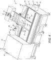
- the energy generation system is housed in an enclosure 3, here an modified sea or shipping container.
- the energy generation system comprises a gasifier 11 which receives waste product and is controlled, in a first phase, to generate syngas or synthetic gas from waste product for combustion downstream in a combustor 51, and subsequently, in a second phase, to incinerate the waste product following extraction of the syngas to provide a stream of hot gas.
- the waste product is a solid waste.
- the waste product can be a refuse-derived fuel (RDF), municipal solid waste (MSW), medical waste, bio-medical waste, agricultural waste, plant waste, animal waste, biomass, textile waste, food waste, pulp waste, tyre waste, plastic waste and manufacturing waste, or any combination thereof, for example, to achieve increased or predetermined calorific value.
- RDF refuse-derived fuel
- MSW municipal solid waste
- medical waste bio-medical waste
- agricultural waste plant waste
- animal waste animal waste
- biomass biomass
- textile waste food waste
- pulp waste pulp waste
- tyre waste plastic waste and manufacturing waste
- the waste product can be combined with a material of higher calorific value, such as by mixing the material of higher calorific value with the waste product.
- the material of higher calorific value could be a waste product.
- the waste product could be municipal solid waste (MSW) in combination with tyre waste, such as tyre particulate, for example, chips or shreds, and/or biomass.
- MSW municipal solid waste
- tyre waste such as tyre particulate, for example, chips or shreds, and/or biomass.
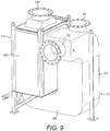
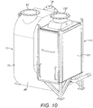
- the gasifier 11 comprises a primary chamber 15 which is loaded with waste product and in which the waste product is heated, a burner 17 for igniting waste product held the primary chamber 15, and an air delivery unit 19 for delivering air into the primary chamber 15.
- waste product is heated in batches, but in an alternative embodiment the waste product could be delivered continuously using a feed unit, such as from a hopper.
- the primary chamber 15 comprises a receptacle 21 and a lid 23 which acts to enclose the receptacle 21.
- the receptacle 21 and the lid 23 are lined with refractory material.
- the primary chamber 15 includes at least one, here a plurality of inlets 27, which are fluidly connected to the air delivery unit 19 and provide for the delivery of air into the primary chamber 15.
- the at least one inlet 27 is located in the lid 23.
- the primary chamber 15 includes at least one, here a plurality of outlets 29, which provide for fluid communication to a secondary chamber 51, either of a stream of syngas or a stream of heated air, as will be described in more detail hereinbelow.
- the burner 17 includes an air supply 33 and a control valve 35, here with a flap valve, which regulates a supply of air to the burner 17 and so enables control of the ignition.
- the burner 17 provides for ignition of the waste product, and control of the rate of ignition allows for control of the rate of burning of the waste product.
- the present inventors have recognized that the rate of burning of the waste product can be carefully regulated to generate syngas without combustion of the same, whereas, if the initial burn or ignition is too great, this can cause acceleration of the rate of burning and an environment in which substantially all of the syngas is combusted.
- the waste product can be utilized more effectively by controlling the heating regime within the gasifier 11, in that, in a first phase, syngas can be extracted from the waste product for downstream combustion, and following extraction of the syngas, in a second phase, the waste product is burnt to provide a stream of hot gas.
- the burner 17 is a diesel burner.
- the air delivery unit 19 includes at least one fan 41, which is controllable to maintain a predetermined delivery of air into the primary chamber 15, and ducting 43 which fluidly connects the at least one fan 41 to the at least one inlet 27 of the primary chamber 15.
- the present inventors have recognized that, by controlling the rate of burning of the waste product, a prolonged generation of syngas can be achieved, but not such as to cause the combustion of that syngas, and this control is provided by regulating delivery of air to the primary chamber 15.
- the air delivery unit 19 is controlled such as to cycle between first periods in which air is delivered to the primary chamber 15 and second periods in which substantially no air is delivered to the primary chamber 15.
- This mode of control prevents acceleration of the burn of the waste product.
- the air delivery unit 19 includes first and second fans 41.
- the air delivery unit 19 comprises a check valve 47, here a butterfly valve, which fluidly connects the at least one inlet 27 of the primary chamber 15 to the at least one fan 41 and prevents backflow upstream of the valve 47.
- a check valve 47 here a butterfly valve
- the energy generation system further comprises a combustor 51 in which syngas, as generated in the first phase of operation of the gasifier 11, is burnt to generate a stream of heated gas.
- the combustor 51 comprises a combustion or secondary chamber 53 which includes at least one inlet 55 which is fluidly connected to the at least one outlet 29 of the primary chamber 15, through which a stream of gas is delivered, syngas in the first phase of operation and heated air in a second, subsequent phase of operation, into the secondary chamber 53, and an outlet 57 through which a stream of heated gas is delivered.
- the combustor 51 further comprises an air delivery unit 59 which is controllable to regulate the amount of air as delivered to the secondary chamber 53, in dependence upon the required energy output from the system.
- the air delivery unit 59 comprises at least one fan 61, here a single fan, and ducting 63 which fluidly connects the at least one fan 61 to the secondary chamber 53.
- the ducting 63 extends at least in part through the primary chamber 15 of the gasifier 11, such that the air which is delivered into the secondary chamber 53 is pre-heated, here to a temperature of at least 350 °C.
- the combustor 51 further comprises at least one, here a plurality of burners 67 which are controlled to pre-heat the secondary chamber 53 and, if required, to introduce additional heat, such that the secondary chamber 53 is maintained at or above a predetermined operating temperature, such that syngas, which is delivered from the gasifier 11 during the first phase of operation of the gasifier 11, is ignited.
- the system includes a lambda sensor 68 for sensing the composition of the stream of hot gas which is delivered from the outlet 57 of the secondary chamber 53, the output of which is utilized to regulate the supply and mass of heated air from the air delivery unit 59, in order to ensure an efficient burn of the syngas.
- the system includes a temperature sensor 70 for measuring the temperature of the stream of hot gas which is delivered from the secondary chamber 53, the output of which is utilized to regulate the temperature of the stream of hot gas which is delivered from the secondary chamber 53.
- the secondary chamber 53 is maintained at a temperature of about 950 °C, optionally at least 850 °C, and optionally in the range of from about 850 °C to about 1000 °C, during the first phase of operation of the gasifier 11.
- the secondary chamber 53 is configured such that the syngas has a residence time of greater than 2 s therein, optionally at least 3 s therein.
- the secondary chamber 53 is pre-heated to an operating temperature, here above 850 °C, using the burners 67, in order to ensure combustion of any syngas.
- the gasifier 11 is controlled, in a first mode during a first phase, to produce syngas, here by igniting the waste product using the burner 17 and regulating air supplied by the air delivery unit 19 to the primary chamber 15 of the gasifier 11, in this embodiment by cycling between first periods in which air is delivered at a first rate to the primary chamber 15 and second periods in which substantially no air is delivered or air is delivered at a second rate, lower than the first rate, to the primary chamber 15.
- This produced syngas is delivered to the secondary chamber 53 and, together with heated air which is delivered to the secondary chamber 53 by the air delivery unit 59, the combustor 51 burns the syngas to generate a stream of hot gas which is delivered from the outlet 57 of the secondary chamber 53 to an air tempering unit 71, as will be described in more detail hereinbelow.
- composition and temperature of the stream of hot gas which is delivered from the secondary chamber 53 is measured using respective ones of the lambda sensor 68 and the temperature sensor 70, and these measurements are used to regulate the supply of air from the air delivery unit 59, in order to ensure an efficient burn of the syngas and maintain the temperature of the stream of hot gas which is delivered from the secondary chamber 53 at a desired temperature or within a desired temperature range, here a temperature of about 900 °C to about 950 °C.
- the gasifier 11 is controlled, in a second mode during a second phase, to increase the rate of burning of the waste product by introducing a greater volume of air into the primary chamber 15, in this embodiment at a third rate, which is greater than the second rate and can be greater than the first rate, using the air delivery unit 19, and maintain a temperature in the primary chamber 15 of at least 1000 °C, optionally at least 1100 °C, to provide a stream of heated air to the secondary chamber 53 at a temperature of at least 1000 °C, optionally at least 1100 °C.
- the air delivered by the air delivery unit 19 is heated in the primary chamber 15 and passes into the secondary chamber 53 at a temperature which requires no additional heat input, and, in this second mode of operation, the burners 67 of the combustor 51 ordinarily provide no heat input.
- the temperature of the stream of hot gas which is delivered from the secondary chamber 53 is measured using the temperature sensor 70, and this measurement is used to regulate the supply of cooler air from the air delivery unit 59, in order to maintain the temperature of the stream of hot gas which is delivered from the secondary chamber 53 at a desired temperature or within a desired temperature range, here a temperature of from about 900 °C to about 950 °C.
- the energy generation system further comprises a gas tempering unit 71 for tempering the stream of heated gas as delivered by the combustor 51.
- the gas tempering unit 71 comprises a tempering chamber 73 which includes a first inlet 75 which is fluidly connected to the outlet 57 of the secondary chamber 53, a second inlet 81 which is fluidly connected to a gas re-circulation unit 231, and an outlet 85 which is fluidly connected to a superheated fluid generation unit 101, as will be described in more detail hereinbelow.
- the stream of heated gas is tempered by controlling the rate at which the re-circulated gas, which is at a lower temperature than the stream of heated gas, is delivered into the tempering chamber 73 in relation to the stream of heated gas.
- the gas tempering unit 71 tempers the stream of heated gas to a temperature of from about 425 °C to about 650 °C, optionally from about 550 °C to about 650 °C.
- the tempering chamber 73 is formed as a dust collector, in this embodiment a cyclone dust collector, for extracting particulate dust from the exhaust gas flow.
- the energy generation system further comprises a superheated fluid generation unit 101 which generates a superheated fluid, in this embodiment superheated steam, from a working fluid, in this embodiment pure, de-mineralised water, optionally containing chemical additives, including oxygen scavengers and corrosion inhibitors.
- a superheated fluid generation unit 101 which generates a superheated fluid, in this embodiment superheated steam, from a working fluid, in this embodiment pure, de-mineralised water, optionally containing chemical additives, including oxygen scavengers and corrosion inhibitors.
- the superheated steam generation unit 101 comprises a superheated fluid generator 111 which receives a stream of heated gas from the gas tempering unit 71, and generates a superheated fluid, in this embodiment superheated steam.
- the superheated steam generation unit 101 further comprises a buffer tank 115 for storing a supply of the working fluid, in this embodiment water, and a first pump 117 for delivering the working fluid from the buffer tank 115 to the superheated steam generator 111 at a required flow rate and/or pressure.
- the superheated steam generation unit 101 further comprises a condenser 121 in this embodiment a plate-type heat exchanger, which receives used steam from at least one steam engine 223 and condenses the used steam to a saturated liquid, in this embodiment water, and a second pump 122 for delivering the water to the buffer tank 115.
- a condenser 121 in this embodiment a plate-type heat exchanger, which receives used steam from at least one steam engine 223 and condenses the used steam to a saturated liquid, in this embodiment water, and a second pump 122 for delivering the water to the buffer tank 115.
- the condenser 121 has an input fluidly connected to a cold water supply of a hot water circuit, and an output from which heated water is delivered, such as for heating, for example, domestic or process heating.
- the superheated steam generator 111, the buffer tank 115, the condenser 121 and the at least one steam engine 223 define a circulatory loop through which the working fluid is circulated, in being converted from a saturated liquid, here water, to a superheated fluid, here superheated steam, and back to a saturated liquid.
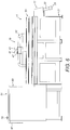
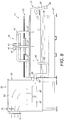
- the superheated steam generator 111 comprises a housing 131, which defines a gas flow path 133 and has an inlet 135 at one, upstream end thereof which is fluidly connected to the outlet 85 of the gas tempering unit 71 and into which a stream of heated gas is delivered, and an outlet 137 at the other, downstream end thereof through which the stream of heated gas exits, and a superheated steam generation assembly 139 which is disposed within the gas flow path 133 of the housing 131.
- the superheated steam generation assembly 139 comprises a heat exchanger unit 169 which is operative to raise the temperature of the working fluid as received from the buffer tank 115, in this embodiment to a temperature of about 260 °C, thereby providing the working fluid as saturated steam.
- the heat exchanger unit 169 comprises at least one heat exchanger circuit 173, which has an input fluidly connected to the buffer tank 115 and an output from which the working fluid, as saturated steam, is delivered.
- the heat exchanger unit 169 comprises at least one, in this embodiment a plurality of heat exchanger modules 175a-d, which are fluidly connected, such that the heat exchanger modules 175a-d each provide part of the flow path of the at least one heat exchanger circuit 173.
- the heat exchanger modules 175a-d define an nxm array, here a 1x4 array.
- the heat exchanger modules 175a-d each comprise first and second outer support elements 177 which are disposed in spaced relation and define a width of the heat exchanger unit 169, and an intermediate support element 178, here central between the outer support elements 177.
- outer support elements 177 of the heat exchanger modules 175a-d are interconnected by sliding couplings, which allow relative movement of the heat exchanger modules 175a-d, thus accommodating relative expansion thereof.
- the heat exchanger modules 175a-d each comprise heat exchanger pipework 185 which extends between the outer support elements 177 of the heat exchanger modules 175a-d, and a plurality of fins 187 which extend in spaced, parallel relation to the outer support elements 177 of the heat exchanger modules 175a-d.
- the fins 187 are illustrated in certain of the views.
- the heat exchanger pipework 185 comprises a plurality of tube sections 191, which are disposed in spaced relation, a plurality of tube end couplings 193 which fluidly connect the open ends of adjacent tube sections 191.
- the tube sections 191 are formed of seamless stainless steel tube, here having an external diameter of 12.7 mm and an about 1.6 mm (16 swg) wall thickness.
- the tube sections 191 and the pipe end couplings 193 provide continuous flow paths which extend in alternate directions across a width of the heat exchanger unit 169, and thus the gas flow passage 133 of the housing 131.
- the fins 187 each comprise a single, continuous sheet element, which includes a plurality of apertures through which extend respective ones of the tube sections 191 of the respective heat exchanger module 175.
- the fins 187 are thermally connected to respective ones of the tube sections 191, here brazed.
- the superheated steam generation assembly 139 further comprises a superheater unit 201 which is located at an upstream end thereof and upstream of the heat exchanger unit 169, and is operative further to raise the temperature of the received working fluid, in this embodiment saturated steam, to a temperature of from about 300 °C to about 420 °C, preferably at a temperature of about 380 °C, and with a pressure of up to 60 bar, thereby providing superheated fluid to the at least one steam engine 223.
- a superheater unit 201 which is located at an upstream end thereof and upstream of the heat exchanger unit 169, and is operative further to raise the temperature of the received working fluid, in this embodiment saturated steam, to a temperature of from about 300 °C to about 420 °C, preferably at a temperature of about 380 °C, and with a pressure of up to 60 bar, thereby providing superheated fluid to the at least one steam engine 223.
- the superheater unit 201 comprises at least one superheater circuit 203, which has an input fluidly connected to the output of the at least one heat exchanger circuit 173 and an output from which a superheated fluid, in this embodiment superheated steam, is delivered.
- the superheater unit 201 comprises first and second outer support elements 207 which are disposed in spaced relation and define a width of the superheater unit 201, and superheater pipework 209 which extends between the outer support elements 207.
- the superheater pipework 209 comprises a plurality of tube sections 211, which are disposed in spaced relation, a plurality of tube end couplings 213 which fluidly connect the open ends of adjacent tube sections 211.
- the tube sections 211 are formed of seamless stainless steel tube, here having an external diameter of 19.05 mm and a wall thickness of 1.65 mm.
- the tube sections 211 and the pipe end couplings 213 provide continuous flow paths which extend in alternate directions across a width of the superheater unit 201, and thus the gas flow passage 133 of the housing 131.
- the steam generation unit 101 further comprises at least one steam engine 223, in this embodiment a steam expander, which receives the superheated steam from the superheated steam generator 111, and at least one power generator 225 which is driven by the at least one steam engine 223 to generate power, in this embodiment electricity, which can be supplied to the electrical grid.
- at least one steam engine 223, in this embodiment a steam expander which receives the superheated steam from the superheated steam generator 111, and at least one power generator 225 which is driven by the at least one steam engine 223 to generate power, in this embodiment electricity, which can be supplied to the electrical grid.
- the energy generation system further comprises a re-circulation unit 231 though which heated gas which is exhausted though the steam generator 111 is partially re-circulated into the gas tempering unit 71.
- the re-circulation unit 231 comprises an inlet 243 which is fluidly connected to the outlet 137 of the superheated steam generator 111, a first outlet 245 which is fluidly connected to the gas tempering unit 71, a second outlet 246 which is fluid connected to atmosphere through a muffler 261, and a gas flow unit 247 which is fluidly connected between the inlet 243 and the first outlet 245 and is controllable to re-circulate a fraction of the exhaust gas to the gas tempering unit 71 for the purpose of tempering the stream of heated gas which is supplied from the combustor 51.
- the fraction of exhaust gas which is re-circulated to the gas tempering unit 71 is determined to maintain a mass balance within the system.
- the gas flow unit 247 comprises a re-circulation fan, and can further comprise at least one valve to regulate relative flows through the first and second outlets 245, 246.
- re-circulation unit 231 further comprises a muffler 261 which is fluidly connected to the second outlet 246, through which that part of the exhaust gas which is not re-circulated is exhausted to atmosphere.
- the energy generation system further comprises a water heater unit 341 which is operative to raise the temperature of a water supply, such as for heating, for example, domestic or process heating.
- the water heater unit 341 comprises at least one heater circuit 343, which has an input fluidly connected to a cold water supply of a hot water circuit, and an output from which heated water is delivered.
- the hot water circuit of the water heater unit 341 can be utilized together with the hot water circuit from the condenser 121 to provide a single supply of hot water.
- the water heater unit 341 comprises first and second outer support elements 347 which are disposed in spaced relation and define a width of the water heater unit 341, and heater pipework 349 which extends between the outer support elements 347.
- the heater pipework 349 comprises a plurality of tube sections 351, which are disposed in spaced relation, and a plurality of tube end couplings 353 which fluidly connect the open ends of adjacent tube sections 351.
- the tube sections 351 are formed of seamless stainless steel tube, here having an external diameter of 19.05 mm and a wall thickness of 1.65 mm.
- the tube sections 351 and the pipe end couplings 353 provide continuous flow paths which extend in alternate directions across a width of the heater unit 341, and thus the gas flow passage 133 of the housing 131.
- the energy generation system has been described in relation to an application for power generation, but the present invention has other application, such as in processing stations where the superheated steam is utilized directly, for example, in pasteurizing food or waste products.
- the described embodiment includes a single steam engine 223 and the steam generation module 139 includes a single fluid circuit associated with the single steam engine 223, but could comprise a plurality of steam engines 223 and the superheated steam generation assembly 139 could include a corresponding plurality of fluid circuits.
Landscapes
- Chemical & Material Sciences (AREA)
- Engineering & Computer Science (AREA)
- Combustion & Propulsion (AREA)
- Oil, Petroleum & Natural Gas (AREA)
- Organic Chemistry (AREA)
- Mechanical Engineering (AREA)
- General Engineering & Computer Science (AREA)
- Environmental & Geological Engineering (AREA)
- Processing Of Solid Wastes (AREA)
- Incineration Of Waste (AREA)
Claims (13)
- System zur Erzeugung von erhitztem Gas aus Abfallprodukten, worin das System umfasst:einen Vergaser (11), der eine Primärkammer (15) zur Aufnahme der Abfallprodukte und mindestens einen Lufteinlass (27) und mindestens einen Gasauslass (29), einen Brenner (17) zum Zünden der in der Primärkammer (15) befindlichen Abfallprodukte und eine Luftzufuhreinheit (19) zum Zuführen von Luft in die Primärkammer (15) durch den mindestens einen Lufteinlass (27) der Primärkammer (15) umfasst; undeine Brennkammer (51), die eine Sekundärkammer (53) mit mindestens einem Gaseinlass (55), der mit dem mindestens einen Gasauslass (29) der Primärkammer (15) fluidmäßig verbunden ist, mindestens einen Lufteinlass undmindestens einen Gasauslass (57), mindestens einen Brenner (67) zum Vorheizen der Sekundärkammer (53) und eine Luftzufuhreinheit (59) zum Zuführen von Luft durch den mindestens einen Lufteinlass der Brennkammer (51) umfasst;dadurch gekennzeichnet, dass:der Vergaser (11) in einem ersten Betriebsmodus durch Regulierung der Luftzufuhr zur Primärkammer (15) gesteuert wird, die Abfallprodukte zu erhitzen, um Synthesegas oder synthetisches Gas aus den Abfallprodukten zu extrahieren und einen Strom von Synthesegas durch den mindestens einen Gasauslass (29) des Vergasers (11) zu liefern, und anschließend in einem zweiten Betriebsmodus, nach der Extraktion des Synthesegases aus den Abfallprodukten, durch Regulieren der Luftzufuhr zu der Primärkammer (15), so dass diese größer ist als die Luftzufuhr zu der Primärkammer (15) in dem ersten Betriebsmodus des Vergasers (11), die Abfallprodukte zu verbrennen, um einen Strom von erhitztem Gas zu liefern, und den Strom von erhitztem Gas durch den mindestens einen Gasauslass (29) des Vergasers (11) zu liefern; unddadurch dass die Brennkammer (51) in einem ersten Betriebsmodus durch Regulieren der Luftzufuhr zu der Sekundärkammer (53) gesteuert wird, die Sekundärkammer (53) auf einer Temperatur von mindestens 850 °C zu halten und den Strom von Synthesegas zu verbrennen, der von der Primärkammer (15) in dem ersten Betriebsmodus des Vergasers (11) zugeführt wird, um einen Strom von erhitztem Gas durch den mindestens einen Gasauslass (57) der Brennkammer (51) zu erzeugen, und in einem zweiten Betriebsmodus den Strom von erhitztem Gas, der von der Primärkammer (15) in dem zweiten Betriebsmodus des Vergasers (11) geliefert wird, durch den mindestens einen Gasauslass (57) der Brennkammer (51) zu liefern.
- System nach Anspruch 1, worin der Brenner (17) des Vergasers (11) eine Luftzufuhr (33) und ein Steuerventil (35) umfasst, das die Luftzufuhr zum Brenner (17) regelt und so die Zündrate der Abfallprodukte steuert.
- System nach Anspruch 1 oder 2, worin die Luftzufuhreinheit (19) des Vergasers (11) mindestens ein Gebläse (41) umfasst, das gesteuert wird, die Zufuhr von Luft in die Primärkammer (15) zu regeln, wahlweise worin die Luftzufuhreinheit (19) des Vergasers (11) ein Rückschlagventil (47) umfasst, das den mindestens einen Lufteinlass (27) der Primärkammer (15) mit dem mindestens einen Gebläse (41) der Luftzufuhreinheit (19) des Vergasers (11) fluidmäßig verbindet, wobei das Rückschlagventil (47) einen Rückfluss stromaufwärts des Rückschlagventils (47) verhindert.
- System nach einem der Ansprüche 1 bis 3, wobei die Luftzufuhreinheit (19) des Vergasers (11) gesteuert wird, zwischen ersten Perioden, in denen der Primärkammer (15) Luft mit einer ersten Rate oder darüber zugeführt wird, und zweiten Perioden, in denen der Primärkammer (15) Luft mit einer zweiten Rate oder darunter zugeführt wird, zyklisch wechselt, wobei der Primärkammer (15) in den zweiten Perioden wahlweise im Wesentlichen keine Luft zugeführt wird.
- System nach einem der Ansprüche 1 bis 4, worin das System ausgestaltet ist, die Abfallprodukte in Chargen oder kontinuierlich zu erhitzen.
- System nach einem der Ansprüche 1 bis 5, worin die Luftzufuhreinheit (59) der Brennkammer (51) einen Kanal (63) umfasst, der sich zumindest teilweise durch die Primärkammer (15) oder an diese angrenzend erstreckt, so dass die Luft, die der Brennkammer (51) durch den mindestens einen Lufteinlass derselben zugeführt wird, vorgewärmt wird.
- System nach Anspruch 6, wobei die Luft, die der Brennkammer (51) durch den mindestens einen Lufteinlass zugeführt wird, auf eine Temperatur von mindestens 350 °C vorgeheizt wird.
- System nach einem der Ansprüche 1 bis 7, worin die Luftzufuhreinheit (59) der Brennkammer (51) mindestens ein Gebläse (61) umfasst, das gesteuert wird, die Zufuhr von Luft durch den mindestens einen Lufteinlass der Brennkammer (51) zu regeln.
- System nach einem der Ansprüche 1 bis 8, wobei die Brennkammer (51) gesteuert wird, die Sekundärkammer (53) in dem ersten Betriebsmodus des Vergasers (11) auf einer Temperatur von mindestens 900 °C oder im Bereich von etwa 850 °C bis etwa 1000 °C zu halten.
- System nach einem der Ansprüche 1 bis 9, worin die Sekundärkammer (53) ausgestaltet ist, dass das Synthesegas darin eine Verweilzeit von mehr als 2 s, wahlweise von mindestens 3 s, aufweist.
- System nach einem der Ansprüche 1 bis 10, wobei der Vergaser (11) in dem zweiten Betriebsmodus des Vergasers (11) gesteuert wird, die Sekundärkammer (53) auf einer Temperatur von mindestens 1000 °C, wahlweise mindestens 1100 °C, zu halten, um der Brennkammer (51) einen Strom erhitzter Luft mit einer Temperatur von mindestens 1000 °C, wahlweise mindestens 1100 °C, zu liefern.
- Verwendung des Systems nach einem der Ansprüche 1 bis 11 mit Abfallprodukten, ausgewählt unter einem aus festem Abfall gewonnenen Brennstoff (RDF), festem Siedlungsabfall (MSW), medizinischen Abfällen, biomedizinischen Abfällen, landwirtschaftlichen Abfällen, pflanzlichen Abfallen, tierischen Abfällen, Biomasse, Textilabfällen, Lebensmittelabfällen, Zellstoffabfällen, Reifenabfällen, Kunststoffabfällen, Produktionsabfällen oder einer Kombination davon.
- Verwendung nach Anspruch 12, wobei das Abfallprodukt mit einem Material mit höherem Heizwert kombiniert wird.
Priority Applications (1)
| Application Number | Priority Date | Filing Date | Title |
|---|---|---|---|
| EP21196730.2A EP3954751A1 (de) | 2015-10-23 | 2016-10-24 | Energieerzeugungssystem |
Applications Claiming Priority (2)
| Application Number | Priority Date | Filing Date | Title |
|---|---|---|---|
| GB1518868.3A GB2543585B (en) | 2015-10-23 | 2015-10-23 | Energy generation system |
| PCT/EP2016/075563 WO2017068188A1 (en) | 2015-10-23 | 2016-10-24 | Energy generation system |
Related Child Applications (2)
| Application Number | Title | Priority Date | Filing Date |
|---|---|---|---|
| EP21196730.2A Division EP3954751A1 (de) | 2015-10-23 | 2016-10-24 | Energieerzeugungssystem |
| EP21196730.2A Division-Into EP3954751A1 (de) | 2015-10-23 | 2016-10-24 | Energieerzeugungssystem |
Publications (2)
| Publication Number | Publication Date |
|---|---|
| EP3365414A1 EP3365414A1 (de) | 2018-08-29 |
| EP3365414B1 true EP3365414B1 (de) | 2022-01-05 |
Family
ID=55130190
Family Applications (2)
| Application Number | Title | Priority Date | Filing Date |
|---|---|---|---|
| EP21196730.2A Withdrawn EP3954751A1 (de) | 2015-10-23 | 2016-10-24 | Energieerzeugungssystem |
| EP16785478.5A Active EP3365414B1 (de) | 2015-10-23 | 2016-10-24 | Energiegenerationssystem |
Family Applications Before (1)
| Application Number | Title | Priority Date | Filing Date |
|---|---|---|---|
| EP21196730.2A Withdrawn EP3954751A1 (de) | 2015-10-23 | 2016-10-24 | Energieerzeugungssystem |
Country Status (3)
| Country | Link |
|---|---|
| EP (2) | EP3954751A1 (de) |
| GB (1) | GB2543585B (de) |
| WO (1) | WO2017068188A1 (de) |
Families Citing this family (2)
| Publication number | Priority date | Publication date | Assignee | Title |
|---|---|---|---|---|
| US10332226B2 (en) * | 2008-08-13 | 2019-06-25 | Greentire Energy Llc | Techniques for locating and operating gasification plant having predominately scrap tire rubber as feedstock |
| CN109127678B (zh) * | 2018-10-23 | 2021-02-02 | 宁波远志立方能源科技有限公司 | 医疗垃圾无害化处理方法 |
Family Cites Families (10)
| Publication number | Priority date | Publication date | Assignee | Title |
|---|---|---|---|---|
| US315096A (en) * | 1885-04-07 | Puddling-furnace | ||
| US233788A (en) * | 1880-10-26 | mitchell | ||
| US4004896A (en) * | 1974-11-21 | 1977-01-25 | University Of Illinois Foundation | Production of water gas |
| US4882903A (en) * | 1988-04-01 | 1989-11-28 | Ch Guernsey & Company | Combined cycle waste-to-energy plant |
| US7229483B2 (en) * | 2001-03-12 | 2007-06-12 | Frederick Michael Lewis | Generation of an ultra-superheated steam composition and gasification therewith |
| JP2003171673A (ja) * | 2001-12-03 | 2003-06-20 | Ebara Corp | ガス発生装置 |
| US20110315096A1 (en) * | 2010-06-01 | 2011-12-29 | ITI Group Corporation | Gasifier Hybrid combined cycle power plant |
| WO2013114070A2 (en) | 2012-01-31 | 2013-08-08 | Clean Thermodynamic Energy Conversion Ltd | Steam generation |
| GB2502115B (en) * | 2012-05-15 | 2015-04-01 | Chinook End Stage Recycling Ltd | Improvements in waste processing |
| EP3287697A1 (de) * | 2012-12-21 | 2018-02-28 | Covanta Energy, LLC | Vergasungsverbrennungssystem |
-
2015
- 2015-10-23 GB GB1518868.3A patent/GB2543585B/en active Active
-
2016
- 2016-10-24 WO PCT/EP2016/075563 patent/WO2017068188A1/en not_active Ceased
- 2016-10-24 EP EP21196730.2A patent/EP3954751A1/de not_active Withdrawn
- 2016-10-24 EP EP16785478.5A patent/EP3365414B1/de active Active
Non-Patent Citations (1)
| Title |
|---|
| None * |
Also Published As
| Publication number | Publication date |
|---|---|
| EP3954751A1 (de) | 2022-02-16 |
| EP3365414A1 (de) | 2018-08-29 |
| WO2017068188A1 (en) | 2017-04-27 |
| GB2543585A (en) | 2017-04-26 |
| GB201518868D0 (en) | 2015-12-09 |
| GB2543585B (en) | 2019-10-16 |
Similar Documents
| Publication | Publication Date | Title |
|---|---|---|
| Al-Attab et al. | Performance of high-temperature heat exchangers in biomass fuel powered externally fired gas turbine systems | |
| KR950019379A (ko) | 화석 연료를 사용하는 발전소의 효율을 증대시키는 장치 | |
| EP3525250A3 (de) | Mikro-kraft-wärme-kopplungssystem | |
| EP3954751A1 (de) | Energieerzeugungssystem | |
| AU5080700A (en) | System for the drying of damp biomass based fuel | |
| CN201973708U (zh) | 一种燃用生物质秸秆的高温高压循环流化床锅炉 | |
| EA032655B1 (ru) | Теплоутилизационная установка и электростанция | |
| CZ26344U1 (cs) | Zařízení pro výrobu elektřiny z pevných paliv, využívající plynovou turbínu | |
| GB2576972A (en) | Energy generation system | |
| WO2014128089A1 (en) | A combined heat and power system | |
| GB2574335A (en) | Energy generation system | |
| GB2576973A (en) | Energy generation system | |
| EP3473820A1 (de) | Verfahren und installation zur co-erzeugung in wärmekraftwerken, insbesondere solche, die mit wasserrohrkessel ausgestattet sind | |
| EP0662191B1 (de) | Verfahren und anlage zum erzeugen von hochtemperaturdampf bei der verbrennung von problembrennstoffen | |
| WO2023148591A2 (en) | Hydrogen generator | |
| RU133566U1 (ru) | Парогазовая установка | |
| EP2913487B1 (de) | Stromerzeugungsvorrichtung und kogenerationssystem | |
| RU2002110420A (ru) | Способ отопления котельных и теплоэлектростанций и устройство для его осуществления | |
| KR102141300B1 (ko) | 고체연료 열병합 발전 시스템 | |
| KR102188155B1 (ko) | 고체연료 직접연소 방식과 가스화 연소 방식을 이용하는 하이브리드 열공급 장치 및 이를 이용하는 열병합 발전 시스템 | |
| RU56969U1 (ru) | Газотурбинная установка | |
| RU2062331C1 (ru) | Энергоблок тепловой электростанции | |
| JP2005147647A (ja) | 排ガスボイラ | |
| Sornek et al. | Straw-Fired Boilers as a Heat Source for Micro-Cogeneration Systems | |
| JP2004108150A (ja) | 熱電併給システム |
Legal Events
| Date | Code | Title | Description |
|---|---|---|---|
| STAA | Information on the status of an ep patent application or granted ep patent |
Free format text: STATUS: UNKNOWN |
|
| STAA | Information on the status of an ep patent application or granted ep patent |
Free format text: STATUS: THE INTERNATIONAL PUBLICATION HAS BEEN MADE |
|
| PUAI | Public reference made under article 153(3) epc to a published international application that has entered the european phase |
Free format text: ORIGINAL CODE: 0009012 |
|
| STAA | Information on the status of an ep patent application or granted ep patent |
Free format text: STATUS: REQUEST FOR EXAMINATION WAS MADE |
|
| 17P | Request for examination filed |
Effective date: 20180521 |
|
| AK | Designated contracting states |
Kind code of ref document: A1 Designated state(s): AL AT BE BG CH CY CZ DE DK EE ES FI FR GB GR HR HU IE IS IT LI LT LU LV MC MK MT NL NO PL PT RO RS SE SI SK SM TR |
|
| AX | Request for extension of the european patent |
Extension state: BA ME |
|
| DAV | Request for validation of the european patent (deleted) | ||
| DAX | Request for extension of the european patent (deleted) | ||
| STAA | Information on the status of an ep patent application or granted ep patent |
Free format text: STATUS: EXAMINATION IS IN PROGRESS |
|
| 17Q | First examination report despatched |
Effective date: 20191002 |
|
| GRAP | Despatch of communication of intention to grant a patent |
Free format text: ORIGINAL CODE: EPIDOSNIGR1 |
|
| STAA | Information on the status of an ep patent application or granted ep patent |
Free format text: STATUS: GRANT OF PATENT IS INTENDED |
|
| INTG | Intention to grant announced |
Effective date: 20210610 |
|
| GRAS | Grant fee paid |
Free format text: ORIGINAL CODE: EPIDOSNIGR3 |
|
| GRAA | (expected) grant |
Free format text: ORIGINAL CODE: 0009210 |
|
| STAA | Information on the status of an ep patent application or granted ep patent |
Free format text: STATUS: THE PATENT HAS BEEN GRANTED |
|
| AK | Designated contracting states |
Kind code of ref document: B1 Designated state(s): AL AT BE BG CH CY CZ DE DK EE ES FI FR GB GR HR HU IE IS IT LI LT LU LV MC MK MT NL NO PL PT RO RS SE SI SK SM TR |
|
| REG | Reference to a national code |
Ref country code: GB Ref legal event code: FG4D |
|
| REG | Reference to a national code |
Ref country code: CH Ref legal event code: EP |
|
| REG | Reference to a national code |
Ref country code: AT Ref legal event code: REF Ref document number: 1460596 Country of ref document: AT Kind code of ref document: T Effective date: 20220115 |
|
| REG | Reference to a national code |
Ref country code: DE Ref legal event code: R096 Ref document number: 602016068097 Country of ref document: DE |
|
| REG | Reference to a national code |
Ref country code: IE Ref legal event code: FG4D |
|
| REG | Reference to a national code |
Ref country code: LT Ref legal event code: MG9D |
|
| REG | Reference to a national code |
Ref country code: NL Ref legal event code: MP Effective date: 20220105 |
|
| REG | Reference to a national code |
Ref country code: AT Ref legal event code: MK05 Ref document number: 1460596 Country of ref document: AT Kind code of ref document: T Effective date: 20220105 |
|
| PG25 | Lapsed in a contracting state [announced via postgrant information from national office to epo] |
Ref country code: NL Free format text: LAPSE BECAUSE OF FAILURE TO SUBMIT A TRANSLATION OF THE DESCRIPTION OR TO PAY THE FEE WITHIN THE PRESCRIBED TIME-LIMIT Effective date: 20220105 |
|
| PG25 | Lapsed in a contracting state [announced via postgrant information from national office to epo] |
Ref country code: SE Free format text: LAPSE BECAUSE OF FAILURE TO SUBMIT A TRANSLATION OF THE DESCRIPTION OR TO PAY THE FEE WITHIN THE PRESCRIBED TIME-LIMIT Effective date: 20220105 Ref country code: RS Free format text: LAPSE BECAUSE OF FAILURE TO SUBMIT A TRANSLATION OF THE DESCRIPTION OR TO PAY THE FEE WITHIN THE PRESCRIBED TIME-LIMIT Effective date: 20220105 Ref country code: PT Free format text: LAPSE BECAUSE OF FAILURE TO SUBMIT A TRANSLATION OF THE DESCRIPTION OR TO PAY THE FEE WITHIN THE PRESCRIBED TIME-LIMIT Effective date: 20220505 Ref country code: NO Free format text: LAPSE BECAUSE OF FAILURE TO SUBMIT A TRANSLATION OF THE DESCRIPTION OR TO PAY THE FEE WITHIN THE PRESCRIBED TIME-LIMIT Effective date: 20220405 Ref country code: LT Free format text: LAPSE BECAUSE OF FAILURE TO SUBMIT A TRANSLATION OF THE DESCRIPTION OR TO PAY THE FEE WITHIN THE PRESCRIBED TIME-LIMIT Effective date: 20220105 Ref country code: HR Free format text: LAPSE BECAUSE OF FAILURE TO SUBMIT A TRANSLATION OF THE DESCRIPTION OR TO PAY THE FEE WITHIN THE PRESCRIBED TIME-LIMIT Effective date: 20220105 Ref country code: ES Free format text: LAPSE BECAUSE OF FAILURE TO SUBMIT A TRANSLATION OF THE DESCRIPTION OR TO PAY THE FEE WITHIN THE PRESCRIBED TIME-LIMIT Effective date: 20220105 Ref country code: BG Free format text: LAPSE BECAUSE OF FAILURE TO SUBMIT A TRANSLATION OF THE DESCRIPTION OR TO PAY THE FEE WITHIN THE PRESCRIBED TIME-LIMIT Effective date: 20220405 |
|
| PG25 | Lapsed in a contracting state [announced via postgrant information from national office to epo] |
Ref country code: PL Free format text: LAPSE BECAUSE OF FAILURE TO SUBMIT A TRANSLATION OF THE DESCRIPTION OR TO PAY THE FEE WITHIN THE PRESCRIBED TIME-LIMIT Effective date: 20220105 Ref country code: LV Free format text: LAPSE BECAUSE OF FAILURE TO SUBMIT A TRANSLATION OF THE DESCRIPTION OR TO PAY THE FEE WITHIN THE PRESCRIBED TIME-LIMIT Effective date: 20220105 Ref country code: GR Free format text: LAPSE BECAUSE OF FAILURE TO SUBMIT A TRANSLATION OF THE DESCRIPTION OR TO PAY THE FEE WITHIN THE PRESCRIBED TIME-LIMIT Effective date: 20220406 Ref country code: FI Free format text: LAPSE BECAUSE OF FAILURE TO SUBMIT A TRANSLATION OF THE DESCRIPTION OR TO PAY THE FEE WITHIN THE PRESCRIBED TIME-LIMIT Effective date: 20220105 Ref country code: AT Free format text: LAPSE BECAUSE OF FAILURE TO SUBMIT A TRANSLATION OF THE DESCRIPTION OR TO PAY THE FEE WITHIN THE PRESCRIBED TIME-LIMIT Effective date: 20220105 |
|
| PG25 | Lapsed in a contracting state [announced via postgrant information from national office to epo] |
Ref country code: IS Free format text: LAPSE BECAUSE OF FAILURE TO SUBMIT A TRANSLATION OF THE DESCRIPTION OR TO PAY THE FEE WITHIN THE PRESCRIBED TIME-LIMIT Effective date: 20220505 |
|
| REG | Reference to a national code |
Ref country code: DE Ref legal event code: R097 Ref document number: 602016068097 Country of ref document: DE |
|
| PG25 | Lapsed in a contracting state [announced via postgrant information from national office to epo] |
Ref country code: SM Free format text: LAPSE BECAUSE OF FAILURE TO SUBMIT A TRANSLATION OF THE DESCRIPTION OR TO PAY THE FEE WITHIN THE PRESCRIBED TIME-LIMIT Effective date: 20220105 Ref country code: SK Free format text: LAPSE BECAUSE OF FAILURE TO SUBMIT A TRANSLATION OF THE DESCRIPTION OR TO PAY THE FEE WITHIN THE PRESCRIBED TIME-LIMIT Effective date: 20220105 Ref country code: RO Free format text: LAPSE BECAUSE OF FAILURE TO SUBMIT A TRANSLATION OF THE DESCRIPTION OR TO PAY THE FEE WITHIN THE PRESCRIBED TIME-LIMIT Effective date: 20220105 Ref country code: EE Free format text: LAPSE BECAUSE OF FAILURE TO SUBMIT A TRANSLATION OF THE DESCRIPTION OR TO PAY THE FEE WITHIN THE PRESCRIBED TIME-LIMIT Effective date: 20220105 Ref country code: DK Free format text: LAPSE BECAUSE OF FAILURE TO SUBMIT A TRANSLATION OF THE DESCRIPTION OR TO PAY THE FEE WITHIN THE PRESCRIBED TIME-LIMIT Effective date: 20220105 Ref country code: CZ Free format text: LAPSE BECAUSE OF FAILURE TO SUBMIT A TRANSLATION OF THE DESCRIPTION OR TO PAY THE FEE WITHIN THE PRESCRIBED TIME-LIMIT Effective date: 20220105 |
|
| PLBE | No opposition filed within time limit |
Free format text: ORIGINAL CODE: 0009261 |
|
| STAA | Information on the status of an ep patent application or granted ep patent |
Free format text: STATUS: NO OPPOSITION FILED WITHIN TIME LIMIT |
|
| PG25 | Lapsed in a contracting state [announced via postgrant information from national office to epo] |
Ref country code: AL Free format text: LAPSE BECAUSE OF FAILURE TO SUBMIT A TRANSLATION OF THE DESCRIPTION OR TO PAY THE FEE WITHIN THE PRESCRIBED TIME-LIMIT Effective date: 20220105 |
|
| 26N | No opposition filed |
Effective date: 20221006 |
|
| PG25 | Lapsed in a contracting state [announced via postgrant information from national office to epo] |
Ref country code: SI Free format text: LAPSE BECAUSE OF FAILURE TO SUBMIT A TRANSLATION OF THE DESCRIPTION OR TO PAY THE FEE WITHIN THE PRESCRIBED TIME-LIMIT Effective date: 20220105 |
|
| PG25 | Lapsed in a contracting state [announced via postgrant information from national office to epo] |
Ref country code: MC Free format text: LAPSE BECAUSE OF FAILURE TO SUBMIT A TRANSLATION OF THE DESCRIPTION OR TO PAY THE FEE WITHIN THE PRESCRIBED TIME-LIMIT Effective date: 20220105 |
|
| REG | Reference to a national code |
Ref country code: CH Ref legal event code: PL |
|
| REG | Reference to a national code |
Ref country code: BE Ref legal event code: MM Effective date: 20221031 |
|
| PG25 | Lapsed in a contracting state [announced via postgrant information from national office to epo] |
Ref country code: LU Free format text: LAPSE BECAUSE OF NON-PAYMENT OF DUE FEES Effective date: 20221024 |
|
| PG25 | Lapsed in a contracting state [announced via postgrant information from national office to epo] |
Ref country code: LI Free format text: LAPSE BECAUSE OF NON-PAYMENT OF DUE FEES Effective date: 20221031 Ref country code: CH Free format text: LAPSE BECAUSE OF NON-PAYMENT OF DUE FEES Effective date: 20221031 |
|
| PG25 | Lapsed in a contracting state [announced via postgrant information from national office to epo] |
Ref country code: BE Free format text: LAPSE BECAUSE OF NON-PAYMENT OF DUE FEES Effective date: 20221031 |
|
| PG25 | Lapsed in a contracting state [announced via postgrant information from national office to epo] |
Ref country code: IE Free format text: LAPSE BECAUSE OF NON-PAYMENT OF DUE FEES Effective date: 20221024 |
|
| PG25 | Lapsed in a contracting state [announced via postgrant information from national office to epo] |
Ref country code: HU Free format text: LAPSE BECAUSE OF FAILURE TO SUBMIT A TRANSLATION OF THE DESCRIPTION OR TO PAY THE FEE WITHIN THE PRESCRIBED TIME-LIMIT; INVALID AB INITIO Effective date: 20161024 |
|
| PG25 | Lapsed in a contracting state [announced via postgrant information from national office to epo] |
Ref country code: CY Free format text: LAPSE BECAUSE OF FAILURE TO SUBMIT A TRANSLATION OF THE DESCRIPTION OR TO PAY THE FEE WITHIN THE PRESCRIBED TIME-LIMIT Effective date: 20220105 |
|
| PG25 | Lapsed in a contracting state [announced via postgrant information from national office to epo] |
Ref country code: MK Free format text: LAPSE BECAUSE OF FAILURE TO SUBMIT A TRANSLATION OF THE DESCRIPTION OR TO PAY THE FEE WITHIN THE PRESCRIBED TIME-LIMIT Effective date: 20220105 |
|
| REG | Reference to a national code |
Ref country code: DE Ref legal event code: R082 Ref document number: 602016068097 Country of ref document: DE Representative=s name: STRAUS, ALEXANDER, DIPL.-CHEM.UNIV. DR.PHIL., DE |
|
| PG25 | Lapsed in a contracting state [announced via postgrant information from national office to epo] |
Ref country code: MT Free format text: LAPSE BECAUSE OF FAILURE TO SUBMIT A TRANSLATION OF THE DESCRIPTION OR TO PAY THE FEE WITHIN THE PRESCRIBED TIME-LIMIT Effective date: 20220105 |
|
| PG25 | Lapsed in a contracting state [announced via postgrant information from national office to epo] |
Ref country code: TR Free format text: LAPSE BECAUSE OF FAILURE TO SUBMIT A TRANSLATION OF THE DESCRIPTION OR TO PAY THE FEE WITHIN THE PRESCRIBED TIME-LIMIT Effective date: 20220105 |
|
| PGFP | Annual fee paid to national office [announced via postgrant information from national office to epo] |
Ref country code: DE Payment date: 20251021 Year of fee payment: 10 |
|
| PGFP | Annual fee paid to national office [announced via postgrant information from national office to epo] |
Ref country code: GB Payment date: 20251007 Year of fee payment: 10 |
|
| PGFP | Annual fee paid to national office [announced via postgrant information from national office to epo] |
Ref country code: IT Payment date: 20251021 Year of fee payment: 10 |
|
| PGFP | Annual fee paid to national office [announced via postgrant information from national office to epo] |
Ref country code: FR Payment date: 20251030 Year of fee payment: 10 |