EP3365575B1 - Kupplungs-drehschwingungsdämpfer-zusammenbau mit einer in einem drehteil eines drehschwingungsdämpfers integrierte hybridtrennkupplung - Google Patents
Kupplungs-drehschwingungsdämpfer-zusammenbau mit einer in einem drehteil eines drehschwingungsdämpfers integrierte hybridtrennkupplung Download PDFInfo
- Publication number
- EP3365575B1 EP3365575B1 EP16788631.6A EP16788631A EP3365575B1 EP 3365575 B1 EP3365575 B1 EP 3365575B1 EP 16788631 A EP16788631 A EP 16788631A EP 3365575 B1 EP3365575 B1 EP 3365575B1
- Authority
- EP
- European Patent Office
- Prior art keywords
- clutch
- vibration damper
- torsional vibration
- rotate
- leaf spring
- Prior art date
- Legal status (The legal status is an assumption and is not a legal conclusion. Google has not performed a legal analysis and makes no representation as to the accuracy of the status listed.)
- Active
Links
Images


Classifications
-
- F—MECHANICAL ENGINEERING; LIGHTING; HEATING; WEAPONS; BLASTING
- F16—ENGINEERING ELEMENTS AND UNITS; GENERAL MEASURES FOR PRODUCING AND MAINTAINING EFFECTIVE FUNCTIONING OF MACHINES OR INSTALLATIONS; THERMAL INSULATION IN GENERAL
- F16D—COUPLINGS FOR TRANSMITTING ROTATION; CLUTCHES; BRAKES
- F16D41/00—Freewheels or freewheel clutches
- F16D41/04—Freewheels or freewheel clutches combined with a clutch for locking the driving and driven members
-
- B—PERFORMING OPERATIONS; TRANSPORTING
- B60—VEHICLES IN GENERAL
- B60K—ARRANGEMENT OR MOUNTING OF PROPULSION UNITS OR OF TRANSMISSIONS IN VEHICLES; ARRANGEMENT OR MOUNTING OF PLURAL DIVERSE PRIME-MOVERS IN VEHICLES; AUXILIARY DRIVES FOR VEHICLES; INSTRUMENTATION OR DASHBOARDS FOR VEHICLES; ARRANGEMENTS IN CONNECTION WITH COOLING, AIR INTAKE, GAS EXHAUST OR FUEL SUPPLY OF PROPULSION UNITS IN VEHICLES
- B60K6/00—Arrangement or mounting of plural diverse prime-movers for mutual or common propulsion, e.g. hybrid propulsion systems comprising electric motors and internal combustion engines
- B60K6/20—Arrangement or mounting of plural diverse prime-movers for mutual or common propulsion, e.g. hybrid propulsion systems comprising electric motors and internal combustion engines the prime-movers consisting of electric motors and internal combustion engines, e.g. HEVs
- B60K6/22—Arrangement or mounting of plural diverse prime-movers for mutual or common propulsion, e.g. hybrid propulsion systems comprising electric motors and internal combustion engines the prime-movers consisting of electric motors and internal combustion engines, e.g. HEVs characterised by apparatus, components or means specially adapted for HEVs
- B60K6/38—Arrangement or mounting of plural diverse prime-movers for mutual or common propulsion, e.g. hybrid propulsion systems comprising electric motors and internal combustion engines the prime-movers consisting of electric motors and internal combustion engines, e.g. HEVs characterised by apparatus, components or means specially adapted for HEVs characterised by the driveline clutches
- B60K6/387—Actuated clutches, i.e. clutches engaged or disengaged by electric, hydraulic or mechanical actuating means
-
- B—PERFORMING OPERATIONS; TRANSPORTING
- B60—VEHICLES IN GENERAL
- B60K—ARRANGEMENT OR MOUNTING OF PROPULSION UNITS OR OF TRANSMISSIONS IN VEHICLES; ARRANGEMENT OR MOUNTING OF PLURAL DIVERSE PRIME-MOVERS IN VEHICLES; AUXILIARY DRIVES FOR VEHICLES; INSTRUMENTATION OR DASHBOARDS FOR VEHICLES; ARRANGEMENTS IN CONNECTION WITH COOLING, AIR INTAKE, GAS EXHAUST OR FUEL SUPPLY OF PROPULSION UNITS IN VEHICLES
- B60K6/00—Arrangement or mounting of plural diverse prime-movers for mutual or common propulsion, e.g. hybrid propulsion systems comprising electric motors and internal combustion engines
- B60K6/20—Arrangement or mounting of plural diverse prime-movers for mutual or common propulsion, e.g. hybrid propulsion systems comprising electric motors and internal combustion engines the prime-movers consisting of electric motors and internal combustion engines, e.g. HEVs
- B60K6/42—Arrangement or mounting of plural diverse prime-movers for mutual or common propulsion, e.g. hybrid propulsion systems comprising electric motors and internal combustion engines the prime-movers consisting of electric motors and internal combustion engines, e.g. HEVs characterised by the architecture of the hybrid electric vehicle
- B60K6/48—Parallel type
-
- F—MECHANICAL ENGINEERING; LIGHTING; HEATING; WEAPONS; BLASTING
- F16—ENGINEERING ELEMENTS AND UNITS; GENERAL MEASURES FOR PRODUCING AND MAINTAINING EFFECTIVE FUNCTIONING OF MACHINES OR INSTALLATIONS; THERMAL INSULATION IN GENERAL
- F16D—COUPLINGS FOR TRANSMITTING ROTATION; CLUTCHES; BRAKES
- F16D13/00—Friction clutches
- F16D13/22—Friction clutches with axially-movable clutching members
- F16D13/38—Friction clutches with axially-movable clutching members with flat clutching surfaces, e.g. discs
- F16D13/52—Clutches with multiple lamellae ; Clutches in which three or more axially moveable members are fixed alternately to the shafts to be coupled and are pressed from one side towards an axially-located member
- F16D13/54—Clutches with multiple lamellae ; Clutches in which three or more axially moveable members are fixed alternately to the shafts to be coupled and are pressed from one side towards an axially-located member with means for increasing the effective force between the actuating sleeve or equivalent member and the pressure member
-
- F—MECHANICAL ENGINEERING; LIGHTING; HEATING; WEAPONS; BLASTING
- F16—ENGINEERING ELEMENTS AND UNITS; GENERAL MEASURES FOR PRODUCING AND MAINTAINING EFFECTIVE FUNCTIONING OF MACHINES OR INSTALLATIONS; THERMAL INSULATION IN GENERAL
- F16D—COUPLINGS FOR TRANSMITTING ROTATION; CLUTCHES; BRAKES
- F16D25/00—Fluid-actuated clutches
- F16D25/08—Fluid-actuated clutches with fluid-actuated member not rotating with a clutching member
- F16D25/082—Fluid-actuated clutches with fluid-actuated member not rotating with a clutching member the line of action of the fluid-actuated members co-inciding with the axis of rotation
-
- F—MECHANICAL ENGINEERING; LIGHTING; HEATING; WEAPONS; BLASTING
- F16—ENGINEERING ELEMENTS AND UNITS; GENERAL MEASURES FOR PRODUCING AND MAINTAINING EFFECTIVE FUNCTIONING OF MACHINES OR INSTALLATIONS; THERMAL INSULATION IN GENERAL
- F16F—SPRINGS; SHOCK-ABSORBERS; MEANS FOR DAMPING VIBRATION
- F16F15/00—Suppression of vibrations in systems; Means or arrangements for avoiding or reducing out-of-balance forces, e.g. due to motion
- F16F15/10—Suppression of vibrations in rotating systems by making use of members moving with the system
- F16F15/12—Suppression of vibrations in rotating systems by making use of members moving with the system using elastic members or friction-damping members, e.g. between a rotating shaft and a gyratory mass mounted thereon
- F16F15/121—Suppression of vibrations in rotating systems by making use of members moving with the system using elastic members or friction-damping members, e.g. between a rotating shaft and a gyratory mass mounted thereon using springs as elastic members, e.g. metallic springs
- F16F15/123—Wound springs
-
- B—PERFORMING OPERATIONS; TRANSPORTING
- B60—VEHICLES IN GENERAL
- B60K—ARRANGEMENT OR MOUNTING OF PROPULSION UNITS OR OF TRANSMISSIONS IN VEHICLES; ARRANGEMENT OR MOUNTING OF PLURAL DIVERSE PRIME-MOVERS IN VEHICLES; AUXILIARY DRIVES FOR VEHICLES; INSTRUMENTATION OR DASHBOARDS FOR VEHICLES; ARRANGEMENTS IN CONNECTION WITH COOLING, AIR INTAKE, GAS EXHAUST OR FUEL SUPPLY OF PROPULSION UNITS IN VEHICLES
- B60K6/00—Arrangement or mounting of plural diverse prime-movers for mutual or common propulsion, e.g. hybrid propulsion systems comprising electric motors and internal combustion engines
- B60K6/20—Arrangement or mounting of plural diverse prime-movers for mutual or common propulsion, e.g. hybrid propulsion systems comprising electric motors and internal combustion engines the prime-movers consisting of electric motors and internal combustion engines, e.g. HEVs
- B60K6/42—Arrangement or mounting of plural diverse prime-movers for mutual or common propulsion, e.g. hybrid propulsion systems comprising electric motors and internal combustion engines the prime-movers consisting of electric motors and internal combustion engines, e.g. HEVs characterised by the architecture of the hybrid electric vehicle
- B60K6/48—Parallel type
- B60K2006/4825—Electric machine connected or connectable to gearbox input shaft
-
- F—MECHANICAL ENGINEERING; LIGHTING; HEATING; WEAPONS; BLASTING
- F16—ENGINEERING ELEMENTS AND UNITS; GENERAL MEASURES FOR PRODUCING AND MAINTAINING EFFECTIVE FUNCTIONING OF MACHINES OR INSTALLATIONS; THERMAL INSULATION IN GENERAL
- F16D—COUPLINGS FOR TRANSMITTING ROTATION; CLUTCHES; BRAKES
- F16D2300/00—Special features for couplings or clutches
- F16D2300/22—Vibration damping
-
- F—MECHANICAL ENGINEERING; LIGHTING; HEATING; WEAPONS; BLASTING
- F16—ENGINEERING ELEMENTS AND UNITS; GENERAL MEASURES FOR PRODUCING AND MAINTAINING EFFECTIVE FUNCTIONING OF MACHINES OR INSTALLATIONS; THERMAL INSULATION IN GENERAL
- F16D—COUPLINGS FOR TRANSMITTING ROTATION; CLUTCHES; BRAKES
- F16D2500/00—External control of clutches by electric or electronic means
- F16D2500/10—System to be controlled
- F16D2500/106—Engine
- F16D2500/1066—Hybrid
-
- Y—GENERAL TAGGING OF NEW TECHNOLOGICAL DEVELOPMENTS; GENERAL TAGGING OF CROSS-SECTIONAL TECHNOLOGIES SPANNING OVER SEVERAL SECTIONS OF THE IPC; TECHNICAL SUBJECTS COVERED BY FORMER USPC CROSS-REFERENCE ART COLLECTIONS [XRACs] AND DIGESTS
- Y02—TECHNOLOGIES OR APPLICATIONS FOR MITIGATION OR ADAPTATION AGAINST CLIMATE CHANGE
- Y02T—CLIMATE CHANGE MITIGATION TECHNOLOGIES RELATED TO TRANSPORTATION
- Y02T10/00—Road transport of goods or passengers
- Y02T10/60—Other road transportation technologies with climate change mitigation effect
- Y02T10/62—Hybrid vehicles
Definitions
- the invention relates to a clutch torsional vibration damper assembly according to the preamble of claim 1. Furthermore, the invention also relates to a hybrid drive train of a vehicle / a drive train of a hybrid vehicle with such a clutch torsional vibration damper assembly.
- the DE 10 2012 222 110 A1 discloses, for example, a clutch device with an actuating device for a drive train of a motor vehicle having an internal combustion engine, an electrical machine and a transmission device.
- the electrical machine has a stator and a rotor in the usual way and the coupling device is arranged in the drive train between the internal combustion engine on the one hand and the electrical machine and the transmission device on the other hand.
- the coupling device and the actuating device are integrated in the rotor of the electrical machine.
- the DE 10 2004 023 673 A1 discloses a method for controlling the drive train of a hybrid vehicle, which has a parallel hybrid drive with a serial arrangement of an internal combustion engine, an electric machine designed as a motor-stator-generator and provided with a flywheel, and a drive transmission connected on the output side to an axle drive.
- the coupling torsional vibration damper assemblies known from the prior art mostly have relatively complex systems, and in particular the coupling devices of these assemblies are often constructed in a relatively complex manner. In at least some versions, the coupling devices can also be actuated only with a relatively complex arrangement.
- a leaf spring unit is mounted in the second coupling component in such a way that an additional axial pressing force for pressing the coupling components against one another (onto the coupling components) is / is introduced in a first direction of rotation of the first coupling component relative to the second coupling component.
- the leaf spring unit has at least one leaf spring that connects two sections of the second coupling component that are separated from one another in a rotationally fixed manner.
- a particularly clever design of the coupling device is implemented as a leaf spring clutch.
- more leaf springs are preferably provided, which are combined to form at least one leaf spring package, the additionally acting axial contact force can be increased further.
- a first section of the second clutch component is preferably designed as a carrier / support component which accommodates at least one (second) friction disk, but preferably a plurality of (second) friction disks, in a rotationally fixed and axially displaceable manner.
- the coupling device is thus made even more compact.
- a second section of the second clutch component is designed as a hub part prepared for the rotationally fixed connection to a drive shaft of a transmission and / or an electromotive machine. This makes the coupling device even more compact.
- first coupling component is further arranged / attached / fastened / provided on the second rotating part, an even more compact design of the coupling-torsional vibration damper assembly is implemented.
- the first clutch component has at least one (first) friction disk, but preferably a plurality of (first) friction disks, which are / are accommodated in the axial direction and are non-rotatably received on a sleeve region of the second rotating part.
- the coupling device is particularly cleverly integrated on the second rotary part of the torsional vibration damper.
- the clutch device can be integrated in a space-saving manner in a radial interior of the second rotating part.
- the invention also relates to a (hybrid) drive train of a (hybrid) motor vehicle, with an internal combustion engine, such as an Otto or diesel engine, a clutch torsional vibration damper assembly according to one of the previously described embodiments, the first rotary part (directly or indirectly ) is rotatably connected to an output shaft of the internal combustion engine, and to an electromotive machine, which is preferably designed as an electromotive drive machine, the drive shaft of which is rotatably connected to the second coupling component of the coupling device.
- an electromotive machine which is preferably designed as an electromotive drive machine, the drive shaft of which is rotatably connected to the second coupling component of the coupling device.
- the electromotive machine has a rotor which is connected in a rotationally fixed manner to the drive shaft, a clutch actuating device being arranged at least in sections (with a concentric master cylinder) in a receiving space of the rotor.
- a compact design of the drive train is also implemented in the axial direction.
- the second rotating part is operatively connected to the drive shaft by means of a freewheel device.
- This also implements a direct torque transmission in a locked position of the freewheel device from the second rotating part to the drive shaft. In an unlocked position of the freewheel device, torque can be transmitted indirectly via the clutch device.
- a clutch torsional vibration damper assembly which has a hybrid separating clutch / K0 clutch as a coupling device in an output flange (the second rotating part) of a torsional vibration damper designed as a dual mass flywheel, the hybrid separating clutch / K0 clutch being constructed similarly to a leaf spring clutch is.
- the torsional vibration damper is designed for a drive train of a hybrid vehicle with an input-side primary mass and an output-side secondary mass. The primary mass is with the internal combustion engine / internal combustion engine connected, while the secondary mass is connected via an output shaft (drive shaft) to the electric machine (electric drive motor, possibly with a generator function) and a starting clutch and a torque converter.
- the secondary mass has an essentially cup-shaped output flange, in the interior of which the output shaft and a separating clutch (K0 clutch) are arranged.
- K0 clutch a separating clutch
- a leaf spring clutch is used in the form of the clutch device.
- the actuation system for the K0 clutch for example a concentric master cylinder, can be accommodated in the rotor of the electric machine at least in sections.
- a freewheel is provided for the transmission of the tensile torque (damped by the torsional vibration damper) from the internal combustion engine to the electric machine.
- the coupling torsional vibration damper assembly 1 is in the FIGS. 2 and 3 particularly well recognizable and presented in detail.
- the clutch / torsional vibration damper assembly 1 is a system / assembly / an arrangement comprising a clutch device 5 and a torsional vibration damper 2, which is designed as a dual-mass flywheel and is therefore also referred to below as a dual-mass flywheel 2.
- the clutch torsional vibration damper assembly 1 is for a hybrid drive train 10 as shown in FIG Fig. 1 is shown schematically, a motor vehicle prepared.
- the clutch torsional vibration damper assembly 1 is consequently used in its operation in such a drive train 10.
- the drive train 10 has one Internal combustion engine 12, an electromotive machine 13.
- a transmission 20 (manual transmission, automatic transmission or dual clutch transmission) is also provided in the drive train 10, a drive shaft 14 of the electromotive machine 13 also directly forming a transmission input shaft of the transmission 20.
- the electromotive machine 13 has a rotor which is connected in a rotationally fixed manner to the drive shaft 14.
- a clutch confirmation device for actuating / engaging and disengaging the clutch device 5 is arranged in sections in a receiving space of the rotor.
- a slave cylinder in the form of a slave cylinder arranged concentrically with the drive shaft 14 is arranged in this receiving space.
- the torsional vibration damper 2 has, according to its design as a dual-mass flywheel 2, a first rotating part 3, which, as in FIG Fig. 3 can be seen particularly well, is essentially disc-shaped.
- This first rotating part 3 has a plurality of fastening means receptacles 25 for fastening on the front to an output shaft / crankshaft 11 of an internal combustion engine 12.
- the fastening means receptacles 25 are used in particular for receiving fastening means designed as fastening screws, which fix / fasten the first rotating part 3 to the output shaft 11 during operation.
- the torsional vibration damper 2 has a second rotary part 4, which, according to the usual structure of the dual mass flywheel 2, is arranged in a spring-elastic and torsional vibration damping manner in its rotational movement relative to the first rotary part 3 by means of several spring elements 29.
- the second rotating part 4 is thus connected in a rotationally fixed manner to the first rotating part 3, but can be rotated in a certain angle of rotation relative to this first rotating part 3 in a spring-elastic manner and damped against torsional vibrations.
- the individual spring elements 29 of the dual-mass flywheel 2 which are arranged here as arc springs in radial spaces between the two rotating parts 3 and 4 and are each supported in the circumferential direction on the first rotating part or on the second rotating part 3, 4, are arranged such that they dampen a torsional irregularity / torsional irregularity generated by the internal combustion engine.
- the second rotating part 4 continues to interact directly during operation by means of a freewheel device 15 / a freewheel with a drive shaft 14 of the electromotive machine 13 / electric machine.
- a freewheel device 15 In a locked position of this freewheel device 15, when the second rotary part 4 is driven with the aid of the first rotary part 3 in a first direction of rotation, as is implemented in a pulling operation of the internal combustion engine 12 and the internal combustion engine 12 has a driving effect on the drive shaft 14, the second is The rotating part 4 is connected in a rotationally fixed manner to the drive shaft 14 via the freewheel device 15 / via a plurality of clamping bodies of the freewheel device 15 such that a drive torque is transmitted directly from the second rotating part 4 to the drive shaft 14.
- the second rotating part 4 and the drive shaft 14 are not directly connected to one another via the freewheel device 15, but can only be connected to one another in a rotationally fixed manner via the coupling device 5, as described in more detail below.
- the clutch torsional vibration damper assembly 1 also has a clutch device 5.
- the coupling device 5 has a first coupling component 6 and a second coupling component 7. Both coupling components 6, 7 are non-rotatably connected to one another in an engaged state / an engaged position of the coupling device 5 and are arranged in a disengaged state / an uncoupled position of the coupling device 5 without torque transmission to one another.
- the second rotating part 4 has a sleeve region 23, which extends a certain distance in the axial direction. In particular, this sleeve area extends in the axial direction out of the area of the receiving space for the spring elements 29. In this exemplary embodiment, this second rotating part 4 already forms the first coupling component 6 directly / directly.
- the sleeve region 23 has an internal toothing on its radial inside 24, which is so is designed such that it receives a plurality of friction disks, which are referred to as first friction disks 18, which can be displaced in the axial direction and in a rotationally fixed manner.
- the first clutch component 6 is thus formed by the inside 24 of the second rotating part 4 and the plurality of first friction disks 18.
- the second clutch component 7 also has a plurality of friction disks, which are referred to below as second friction disks 22. These second friction disks 22 are also displaceable relative to one another in the axial direction. In this case, a second friction disk 22 is arranged between two first friction disks 18 arranged adjacent to one another in the axial direction.
- the friction disks 18 and 22 are dimensioned such that the clutch device 5 is also referred to as a multi-plate clutch.
- the friction elements 18 and 22 which form friction plates are pressed / pressed against one another in the axial direction in an engaged position in such a way that they are rotationally connected to one another with frictional engagement. In a disengaged position of the clutch device 5, the friction disks 18 and 22 are in turn not in frictional engagement with one another, but are freely rotatable relative to one another.
- the second coupling component 7 also has a first section 16, which essentially forms an inner basket of the coupling device 5.
- the second friction disks 18 are accommodated on a toothing, namely on an outer toothing, in a rotationally fixed and axially displaceable manner.
- the first section 16 thus forms a basket-shaped carrier 19.
- the second coupling component 7 also includes a second section 17, which is designed as a hub part 21 and is made materially separate from the first section 16.
- the hub part 21 is non-rotatably connected to the drive shaft 14 during operation by means of a serration connection.
- the clutch device 5 is designed as a leaf spring clutch.
- the two sections 16 and 17 are connected to one another in a rotationally fixed manner via a leaf spring unit 8.
- the arrangement and design of the leaf spring unit 8 is also particularly good in cooperation with the FIGS. 4 to 7 to recognize.
- several form along the circumference / in the circumferential direction The leaf spring unit 8 distributes the leaf spring assemblies 26 distributed between the coupling device 5 and the second rotating part 4. With a first end 27, each of these leaf spring assemblies 26 is connected to the first section 16 by riveting and is connected in a rotationally fixed manner with a second end 28 to the hub part / the second section 17.
- the leaf spring assemblies 26 each have in the usual way a plurality, here six leaf springs 9, which, when placed one above the other, form a common spring device in the form of the leaf spring assembly 26.
- the leaf spring assemblies 26 are designed and clamped during operation between the two sections 16 and 17 in such a way that the leaf spring unit generates a certain axial prestressing force between the two sections 16 and 17 during operation.
- the leaf springs 9 of the leaf spring assemblies 26 also extend somewhat in the axial direction, so that the leaf springs 9 run obliquely to a radial direction. This has the effect that when torque is transmitted from the drive shaft 14 in the direction of the internal combustion engine 12 / the output shaft 11 in the overrun mode of the internal combustion engine and in the coupled state of the clutch device 5, the leaf spring assemblies 26 are driven in the circumferential direction in such a way that they also develop an axial preload force ,
- the arrangement of the leaf spring unit 8 is chosen such that the friction disks 18 and 22 are pressed against one another with an additional pressing force by this axial pretensioning force (in overrun mode of the internal combustion engine 12). As a result, a particularly stable engaged position of the clutch device 5 is implemented.
- a damper torsional vibration damper 2 is connected between the internal combustion engine (internal combustion engine 12) and drive train 10. This is screwed directly onto the crankshaft (output shaft 11) and, viewed in simplified terms, consists of the primary flywheel / first rotating part 3 (combustion side), the arc springs 29 and the secondary flywheel / second rotating part 4 (transmission side).
- a large freewheel 15 is used for the transmission of the pulling torque, which the damped combustion torque with the gear 20 / E machine (electromotive Machine 13) transmits.
- a leaf spring clutch 5 is used in order to be able to transmit a thrust torque (engine brake / start of the combustion engine).
- the leaf spring clutch 5 can be designed to be normally open or normally closed.
- the leaf spring clutch 5 is preferably designed so that the self-reinforcement acts in the direction of thrust and thus the actuating force can be significantly reduced.
- the electric machine 13 is mounted axially behind the clutch 5. In its rotor, for example, a CSC (concentric slave cylinder / concentric slave cylinder) for actuating the clutch 5 can be integrated to save space.
Landscapes
- Engineering & Computer Science (AREA)
- General Engineering & Computer Science (AREA)
- Mechanical Engineering (AREA)
- Chemical & Material Sciences (AREA)
- Combustion & Propulsion (AREA)
- Transportation (AREA)
- Physics & Mathematics (AREA)
- Acoustics & Sound (AREA)
- Aviation & Aerospace Engineering (AREA)
- Mechanical Operated Clutches (AREA)
- Hybrid Electric Vehicles (AREA)
Description
- Die Erfindung betrifft einen Kupplungs-Drehschwingungsdämpfer-Zusammenbau gemäß dem Obergriff des Anspruchs 1. Desweiteren betrifft die Erfindung auch einen hybriden Antriebsstrang eines Fahrzeuges / einen Antriebsstrang eines Hybridfahrzeuges mit einem solchen Kupplungs-Drehschwingungsdämpfer-Zusammenbau.
- Aus dem Stand der Technik sind solche Kupplungs-Drehschwingungsdämpfer-Zusammenbauten bereits gattungsgemäß bekannt. Die
DE 10 2012 222 110 A1 offenbart etwa eine Kupplungseinrichtung mit einer Betätigungseinrichtung für einen Antriebsstrang eines Kraftfahrzeuges aufweisend eine Brennkraftmaschine, eine elektrische Maschine sowie eine Getriebeeinrichtung. Die elektrische Maschine weist auf übliche Weise einen Stator und einen Rotor auf und die Kupplungseinrichtung ist in dem Antriebsstrang zwischen der Brennkraftmaschine einerseits und der elektrischen Maschine sowie der Getriebeeinrichtung andererseits angeordnet. Die Kupplungseinrichtung und die Betätigungseinrichtung sind in dem Rotor der elektrischen Maschine integriert. - Die
DE 10 2004 023 673 A1 offenbart ein Verfahren zur Steuerung des Antriebsstrangs eines Hybridfahrzeuges, das einen Parallel-Hybridantrieb mit einer seriellen Anordnung eines Verbrennungsmotors, einer als Motor-Stator-Generator ausgebildeten und mit einer Schwungmasse versehenen Elektromaschine und eines abtriebsseitig mit einem Achsantrieb verbundenen Fahrgetriebes aufweist. - Desweiteren offenbart die
DE 10 2014 203 954 A1 einen Kupplungs-Drehschwingungsdämpfer-Zusammenbau gemäß dem Oberbegriff des Anspruchs 1. - Bezüglich weiteren Standes der Technik wird auf die
EP 1 555 450 A1 , dieDE 10 2014 206 844 A1 , dieDE 10 2011 106399 A1 , dieUS 2007/037659 A1 , dieCN 103 277 422 A und dieJP 2010 071 380 A - Die aus dem Stand der Technik bekannten Kupplungs-Drehschwingungsdämpfer-Zusammenbauten weisen jedoch zumeist relativ aufwändig ausgestaltete Systeme auf, wobei insbesondere die Kupplungseinrichtungen dieser Zusammenbauten häufig relativ aufwändig aufgebaut sind. Auch können die Kupplungseinrichtungen in zumindest manchen Ausführungen nur mit einer relativ komplexen Anordnung betätigt werden.
- Es ist daher die Aufgabe der vorliegenden Erfindung, diese aus dem Stand der Technik bekannten Nachteile zu beheben und ein System aus Kupplung und Drehschwingungsdämpfer zur Verfügung zu stellen, das in jeglichen Betriebszuständen eines hybriden Antriebsstranges möglichst verlässlich zwischen den einzelnen Zuständen umschaltbar sein soll, wobei dessen Aufbau gleichzeitig deutlich vereinfacht werden soll.
- Diese Aufgabe wird mit den in den unabhängigen Ansprüchen angegebenen Maßnahmen gelöst.
- Weitere vorteilhafte Ausgestaltungen der vorliegenden Erfindung sind Gegenstand der abhängigen Ansprüche.
- Eine Blattfedereinheit ist derart in dem zweiten Kupplungsbestandteil angebracht ist, dass durch diese Blattfedereinheit in einer ersten Drehrichtung des ersten Kupplungsbestandteils relativ zu dem zweiten Kupplungsbestandteil eine zusätzliche axiale Anpresskraft zum Aneinanderandrücken der Kupplungsbestandteile (auf die Kupplungsbestandteile) eingeleitet ist / wird.
- Dadurch wird gewährleistet, dass die Kupplungseinrichtung unter einem geringen technischen Aufwand in ihrem eingekuppelten Zustand stets mit einer ausreichenden Festigkeit geschlossen ist und die Kupplungsbestandteile besonders stabil drehfest miteinander verbunden sind. Die Dauerfestigkeit des erfindungsgemäßen Kupplungs-Drehschwingungsdämpfer-Zusammenbaus wird dadurch ebenfalls deutlich erhöht.
- Von Vorteil ist es auch, wenn die Blattfedereinheit zumindest eine Blattfeder aufweist, die zwei stofflich voneinander getrennte Abschnitte des zweiten Kupplungsbestandteiles drehfest miteinander verbindet. Dadurch ist eine besonders geschickte Ausgestaltung der Kupplungseinrichtung als eine Blattfederkupplung umgesetzt. Sind weiter bevorzugt jedoch mehrere Blattfedern vorgesehen, die zu zumindest einem Blattfederpaket zusammengesetzt sind, kann die zusätzlich wirkende axiale Anpresskraft weiter erhöht werden.
- Ein erster Abschnitt des zweiten Kupplungsbestandteiles ist dabei vorzugsweise als ein, zumindest eine (zweite) Reibscheibe, vorzugsweise jedoch mehrere (zweite) Reibscheiben, drehfest sowie axial verschiebbar aufnehmender Träger / Tragbestandteil ausgebildet. Somit ist die Kupplungseinrichtung noch kompakter ausgebildet.
- In diesem Zusammenhang ist es zudem vorteilhaft, wenn ein zweiter Abschnitt des zweiten Kupplungsbestandteiles als ein zur drehfesten Verbindung mit einer Antriebswelle eines Getriebes und/oder einer elektromotorischen Maschine vorbereitetes Nabenteil ausgebildet ist. Dadurch ist die Kupplungseinrichtung noch kompakter ausgestaltet.
- Ist der erste Kupplungsbestandteil im Weiteren an dem zweiten Drehteil angeordnet / angebracht / befestigt / vorgesehen, ist eine noch kompaktere Ausbildung des Kupplungs-Drehschwingungsdämpfer-Zusammenbau umgesetzt.
- Der erste Kupplungsbestandteil weist zumindest eine (erste) Reibscheibe, vorzugsweise jedoch mehrere (erste) Reibscheiben auf, die in axialer Richtung verschiebbar sowie drehfest an einem Hülsenbereich des zweiten Drehteils aufgenommen ist / sind. Dadurch ist die Kupplungseinrichtung besonders geschickt an dem zweiten Drehteil des Drehschwingungsdämpfers integriert.
- Da die zumindest eine (erste) Reibscheibe des erstes Kupplungsbestandteils an einer radialen Innenseite des Hülsenbereiches angeordnet / aufgenommen ist, istdie Kupplungseinrichtung besonders platzsparend in einem radialen Innenraum des zweiten Drehteils integrierbar.
- Im Weiteren betrifft die Erfindung auch einen (hybriden) Antriebsstrang eines (Hybrid-) Kraftfahrzeuges, mit einer Verbrennungskraftmaschine, wie einem Otto- oder Dieselmotor, einem Kupplungs-Drehschwingungsdämpfer-Zusammenbau nach einem der zuvor beschriebenen Ausführungsformen, wobei das erste Drehteil (unmittelbar oder mittelbar) drehfest mit einer Ausgangswelle der Verbrennungskraftmaschine verbunden ist, sowie mit einer elektromotorischen Maschine, die vorzugsweise als elektromotorische Antriebsmaschine ausgestaltet ist, deren Antriebswelle drehfest mit dem zweiten Kupplungsbestandteil der Kupplungseinrichtung verbunden ist. Dadurch ist auch ein Antriebsstrang besonders effektiv aufgebaut.
- In einer weiteren Ausführung ist es dabei auch von Vorteil, wenn die elektromotorische Maschine einen Rotor aufweist, der drehfest mit der Antriebswelle verbunden ist, wobei eine Kupplungsbetätigungseinrichtung zumindest abschnittsweise (mit einem konzentrischen Geberzylinder) in einem Aufnahmeraum des Rotors angeordnet ist. Dadurch ist eine kompakte Ausbildung des Antriebsstranges auch in axialer Richtung umgesetzt.
- In diesem Zusammenhang ist es auch vorteilhaft, wenn das zweite Drehteil mittels einer Freilaufeinrichtung mit der Antriebswelle wirkverbunden ist. Dadurch ist auch eine direkte Drehmomentübertragung in einer Sperrstellung der Freilaufeinrichtung von dem zweiten Drehteil auf die Antriebswelle umgesetzt. In einer Entsperrstellung der Freilaufeinrichtung kann Drehmoment indirekt über die Kupplungseinrichtung übertragen werden.
- In anderen Worten ausgedrückt, ist somit ein Kupplungs-Drehschwingungsdämpfer-Zusammenbau umgesetzt, der eine Hybridtrennkupplung / K0-Kupplung als Kupplungseinrichtung in einem Abtriebsflansch (dem zweiten Drehteil) eines als Zweimassenschwungrad ausgebildeten Drehschwingungsdämpfers aufweist, wobei die Hybridtrennkupplung / K0-Kupplung ähnlich einer Blattfederkupplung aufgebaut ist. Der Drehschwingungsdämpfer ist für einen Antriebsstrang eines Hybridfahrzeuges mit einer eingangsseitigen Primärmasse und einer ausgangsseitigen Sekundärmasse ausgebildet. Die Primärmasse ist mit dem Verbrennungsmotor / der Verbrennungskraftmaschine verbunden, während die Sekundärmasse über eine Ausgangswelle (Antriebswelle) mit der Elektromaschine (elektrischer Fahrmotor ggf. mit Generatorfunktion) und einer Anfahrkupplung sowie einem Drehmomentwandler verbunden ist. Die Sekundärmasse weist einen im Wesentlichen topfförmig ausgebildeten Abtriebsflansch auf, in dessen Innerem die Abtriebswelle und eine Trennkupplung (K0-Kupplung) angeordnet sind. Erfindungsgemäß ist eine Blattfederkupplung in Form der Kupplungseinrichtung eingesetzt. Das Betätigungssystem für die K0-Kupplung, bspw. ein konzentrischer Geberzylinder, kann im Rotor der Elektromaschine zumindest abschnittsweise untergebracht sein. Für die Übertragung des (durch den Drehschwingungsdämpfer gedämpften) Zugmoments vom Verbrennungsmotor zur Elektromaschine ist ein Freilauf vorgesehen.
- Die Erfindung wird nun nachfolgend anhand von Figuren in einem Ausführungsbeispiel näher erläutert.
- Es zeigen:
- Fig. 1
- eine schematische Ansicht eines Antriebsstranges aufweisend einen erfin-dungsgemäßen Kupplungs-Drehschwingungsdämpfer-Zusammenbau,
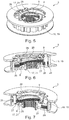
- Fig. 2
- eine Längsschnittdarstellung des erfindungsgemäßen Kupplungs-Drehschwingungsdämpfer-Zusammenbaus, wie er in dem Antriebsstrang nach
Fig. 1 eingesetzt ist, wobei insbesondere der Aufbau des Drehschwin-gungsdämpfers sowie der Kupplungseinrichtung gut erkennbar ist, - Fig. 3
- eine perspektivische Darstellung des erfindungsgemäßen Kupplungs-Drehschwingungsdämpfer-Zusammenbaus nach
Fig. 2 im Halbschnitt, in der das erste Drehteil des Drehschwingungsdämpfers gut erkennbar ist, - Fig. 4
- eine perspektivische Darstellung der Kupplungseinrichtung, wie sie in dem er-findungsgemäßen Kupplungs-Drehschwingungsdämpfer-Zusammenbau nach den
Fign. 2 und3 eingesetzt ist, in der zum einen die Außenverzahnung der ersten Reibscheiben des ersten Kupplungsbestandteiles zu erkennen ist so-wie zum anderen die Anbringung der Blattfedereinheit radial innerhalb dieser ersten Reibscheiben gut zu erkennen ist, - Fig. 5
- eine perspektivische Darstellung der Kupplungseinrichtung nach
Fig. 4 , wobei auf die Darstellung der Reibscheiben der beiden Kupplungsbestandteile ver-zichtet ist, sodass die die zweiten Reibscheiben aufnehmende Außenverzah-nung des zweiten Kupplungsbestandteiles erkennbar ist, - Fig. 6
- eine perspektivische Darstellung der Kupplungseinrichtung nach
Fig. 5 im Halbschnitt, in dem wiederum die Blattfedern / Blattfederpakete der Blattfe-dereinheit deutlich zu erkennen sind, wobei die Schnittebene so gewählt ist, dass die die Anbringung der Blattfedern / des Blattfederpaketes an einem zweiten Abschnitt des zweiten Kupplungsbestandteiles erkennbar ist, und - Fig. 7
- eine perspektivische Darstellung der Kupplungseinrichtung nach
Fig. 5 im Halbschnitt, wobei die Schnittebene so gewählt ist, dass die Befestigung eines der Blattfedern / Blattfederpakete an einem ersten Abschnitt des zweiten Kupplungsbestandteiles deutlich zu erkennen ist. - Die Figuren sind lediglich schematischer Natur und dienen ausschließlich dem Verständnis der Erfindung. Die gleichen Elemente sind mit denselben Bezugszeichen versehen.
- Der erfindungsgemäße Kupplungs-Drehschwingungsdämpfer-Zusammenbau 1 ist in den
Fign. 2 und3 besonders gut erkennbar sowie detailliert dargestellt. Der Kupplungs-Drehschwingungsdämpfer-Zusammenbau 1 ist ein System / Zusammenbau / eine Anordnung aus einer Kupplungseinrichtung 5 sowie einem Drehschwingungsdämpfer 2, der als Zweimassenschwungrad ausgebildet ist und somit alternativ nachfolgend auch als Zweimassenschwungrad 2 bezeichnet ist. Der Kupplungs-Drehschwingungsdämpfer-Zusammenbau 1 ist für einen hybriden Antriebsstrang 10, wie er inFig. 1 schematisch zu erkennen ist, eines Kraftfahrzeuges vorbereitet. Der Kupplungs-Drehschwingungsdämpfer-Zusammenbau 1 ist folglich in seinem Betrieb in einem solchen Antriebsstrang 10 eingesetzt. Der Antriebsstrang 10 weist neben einer Verbrennungskraftmaschine 12, eine elektromotorische Maschine 13 auf. Auch ist ein Getriebe 20 (manuelles Schaltgetriebe, automatisches Schaltgetriebe oder Doppelkupplungsgetriebe) in dem Antriebsstrang 10 vorgesehen, wobei eine Antriebswelle 14 der elektromotorischen Maschine 13 unmittelbar auch eine Getriebeeingangswelle des Getriebes 20 ausbildet. Wie hier der Übersichtlichkeit halber nicht weiter dargestellt, weist die elektromotorische Maschine 13 einen Rotor auf, der drehfest mit der Antriebswelle 14 verbunden ist. Eine Kupplungsbestätigungseinrichtung zum Betätigen / Ein- und Ausrücken der Kupplungseinrichtung 5 ist abschnittsweise in einem Aufnahmeraum des Rotors angeordnet. Insbesondere ist ein Nehmerzylinder in Form eines konzentrisch zur Antriebswelle 14 angeordneten Nehmerzylinders in diesem Aufnahmeraum angeordnet. - Der Drehschwingungsdämpfer 2 weist entsprechend seiner Ausbildung als Zweimassenschwungrad 2 zunächst ein erstes Drehteil 3 auf, das, wie in
Fig. 3 besonders gut zu erkennen ist, im Wesentlichen scheibenförmig ausgestaltet ist. Dieses erste Drehteil 3 weist mehrere Befestigungsmittelaufnahmen 25 zum stirnseitigen Befestigen an einer Ausgangswelle / Kurbelwelle 11 einer Verbrennungskraftmaschine 12 auf. Die Befestigungsmittelaufnahmen 25 dienen hierbei insbesondere zum Aufnehmen von als Befestigungsschrauben ausgebildeten Befestigungsmitteln, die das erste Drehteil 3 im Betrieb an der Ausgangswelle 11 festlegen / befestigen. Neben diesem ersten Drehteil 3 weist der Drehschwingungsdämpfer 2 ein zweites Drehteil 4 auf, das, gemäß dem üblichen Aufbau des Zweimassenschwungrades 2, mittels mehrerer Federelemente 29 federelastisch sowie drehschwingungsgedämpft in seiner Drehbewegung relativ zu dem ersten Drehteil 3 angeordnet ist. Das zweite Drehteil 4 ist somit mit dem ersten Drehteil 3 drehfest verbunden, jedoch in einem bestimmten Verdrehwinkelbereich gegenüber diesem ersten Drehteil 3 federelastisch sowie drehschwingungsgedämpft verdrehbar. Die einzelnen Federelemente 29 des Zweimassenschwungrades 2, die hier als Bogenfedern in radialen Zwischenräumen zwischen den beiden Drehteilen 3 und 4 angeordnet sind und jeweils in Umfangsrichtung an dem ersten Drehteil bzw. an dem zweiten Drehteil 3, 4 abgestützt sind, sind so angeordnet, dass sie eine durch die Verbrennungskraftmaschine erzeugte Drehschwingungsunförmigkeit / Drehunförmigkeit abdämpfen. - Das zweite Drehteil 4, wie in
Fig. 2 auch gut zu erkennen, wirkt im Betrieb weiterhin unmittelbar mittels einer Freilaufeinrichtung 15 / einem Freilauf mit einer Antriebswelle 14 der elektromotorischen Maschine 13 / Elektromaschine zusammen. In einer Sperrstellung dieser Freilaufeinrichtung 15, bei einem Antreiben des zweiten Drehteils 4 mit Hilfe des ersten Drehteils 3 in einer ersten Drehrichtung, wie es bei einem Zugbetrieb der Verbrennungskraftmaschine 12 umgesetzt ist und wobei die Verbrennungskraftmaschine 12 antreibend auf die Antriebswelle 14 einwirkt, ist das zweite Drehteil 4 über die Freilaufeinrichtung 15 / über mehrere Klemmkörper der Freilaufeinrichtung 15 so mit der Antriebswelle 14 drehfest verbunden, dass ein Antriebsmoment direkt von dem zweiten Drehteil 4 an die Antriebswelle 14 übertragen wird. In einer Entsperrstellung der Freilaufeinrichtung 15, in der sich das zweite Drehteil 4 in einer zu der ersten Drehrichtung entgegengesetzten zweiten Drehrichtung dreht oder das erste Drehteil 4 langsamer als die Antriebswelle 14 in der ersten Drehrichtung dreht (d.h. in einem Schubzustand der Verbrennungskraftmaschine, etwa bei einem Start der Verbrennungskraftmaschine mit Hilfe der elektromotorischen Maschine 13 oder bei einer Motorbremse), sind das zweite Drehteil 4 und die Antriebswelle 14 nicht direkt über die Freilaufeinrichtung 15 miteinander drehverbunden, sondern lediglich über die Kupplungseinrichtung 5, wie nachfolgend näher beschrieben, drehfest miteinander verbindbar. - Dementsprechend weist der Kupplungs-Drehschwingungsdämpfer-Zusammenbau 1 auch eine Kupplungseinrichtung 5 auf. Die Kupplungseinrichtung 5 weist einen ersten Kupplungsbestandteil 6 sowie einen zweiten Kupplungsbestandteil 7 auf. Beide Kupplungsbestandteile 6, 7 sind in einem eingekuppelten Zustand / einer eingekuppelten Stellung der Kupplungseinrichtung 5 drehfest miteinander verbunden und in einem ausgekuppelten Zustand / einer ausgekuppelten Stellung der Kupplungseinrichtung 5 drehmomentenübertragungslos zueinander angeordnet. Wie in
Fig. 2 gut zu erkennen, weist das zweite Drehteil 4 einen Hülsenbereich 23 auf, der sich um einen gewissen Abstand in axialer Richtung erstreckt. Insbesondere erstreckt sich dieser Hülsenbereich in axialer Richtung aus dem Bereich des Aufnahmeraums für die Federelemente 29 hinaus. Dieser zweite Drehteil 4 bildet in diesem Ausführungsbeispiel den ersten Kupplungsbestandteil 6 bereits unmittelbar / direkt aus. Hierfür weist der Hülsenbereich 23 eine Innenverzahnung an seiner radialen Innenseite 24 auf, die so ausgestaltet ist, dass sie mehrere Reibscheiben, die als erste Reibscheiben 18 bezeichnet sind, in axialer Richtung verschiebbar sowie drehfest aufnimmt. Der erste Kupplungsbestandteil 6 ist somit durch die Innenseite 24 des zweiten Drehteils 4 sowie die mehreren ersten Reibscheiben 18 gebildet. - Auch der zweite Kupplungsbestandteil 7 weist mehrere Reibscheiben, die nachfolgend als zweite Reibscheiben 22 bezeichnet sind, auf. Auch diese zweiten Reibscheiben 22 sind in axialer Richtung relativ zueinander verschiebbar. Dabei ist jeweils eine zweite Reibscheibe 22 zwischen zwei in axialer Richtung benachbart zueinander angeordneten ersten Reibscheiben 18 angeordnet. Die Reibscheiben 18 sowie 22 sind hierbei derart dimensioniert, dass die Kupplungseinrichtung 5 auch als Lamellenkupplung bezeichnet ist. Die Reiblamellen ausbildenden Reibelemente 18 sowie 22 sind in einer eingekuppelten Stellung so in axialer Richtung aneinander angedrückt / angepresst, dass sie unter Reibkraftschluss miteinander drehverbunden sind. In einer ausgekuppelten Stellung der Kupplungseinrichtung 5 sind die Reibscheiben 18 und 22 wiederum nicht reibkraftschlüssig aneinander anliegend, sondern frei relativ zueinander verdrehbar.
- Der zweite Kupplungsbestandteil 7 weist weiterhin einen ersten Abschnitt 16 auf, der im Wesentlichen einen Innenkorb der Kupplungseinrichtung 5 ausbildet. An diesem Innenkorb / ersten Abschnitt 16 sind die zweiten Reibscheiben 18 an einer Verzahnung, nämlich an einer Außenverzahnung, drehfest sowie axial verschiebbar aufgenommen. Somit bildet der erste Abschnitt 16 einen korbförmigen Träger 19 aus. Neben dem ersten Abschnitt 16 gehört zu dem zweiten Kupplungsbestandteil 7 auch ein zweiter Abschnitt 17, der als Nabenteil 21 ausgestaltet ist und stofflich getrennt von dem ersten Abschnitt 16 ausgebildet ist. Das Nabenteil 21 ist im Betrieb drehfest mittels einer Kerbzahnverbindung mit der Antriebswelle 14 verbunden.
- Erfindungsgemäß ist die Kupplungseinrichtung 5 als eine Blattfederkupplung ausgestaltet. Hierfür sind die beiden Abschnitte 16 und 17 über eine Blattfedereinheit 8 drehfest miteinander verbunden. Die Anordnung sowie Ausgestaltung der Blattfedereinheit 8 ist auch besonders gut in Zusammenwirkung mit den
Fign. 4 bis 7 zu erkennen. Dabei bilden in dieser Ausführung mehrere, entlang des Umfangs / in Umfangsrichtung der Kupplungseinrichtung 5 / des zweiten Drehteils 4 verteilt angeordnete Blattfederpakete 26 die Blattfedereinheit 8 aus. Mit einem ersten Ende 27 ist jedes dieser Blattfederpakete 26 über eine Vernietung mit dem ersten Abschnitt 16 verbunden sowie mit einem zweiten Ende 28 mit dem Nabenteil / dem zweiten Abschnitt 17 drehfest verbunden. Die Blattfederpakete 26 weisen dabei jeweils auf übliche Weise mehrere, hier sechs Blattfedern 9 auf, die übereinander gelegt eine gemeinsame Federeinrichtung in Form des Blattfederpaketes 26 bilden. Die Blattfederpakete 26 sind so ausgestaltet und im Betrieb zwischen den beiden Abschnitten 16 und 17 eingespannt, dass die Blattfedereinheit eine gewisse axiale Vorspannkraft zwischen den beiden Abschnitten 16 und 17 im Betrieb erzeugt. - Wie in
Fig. 6 auch besonders gut zu erkennen ist, erstrecken sich die Blattfedern 9 der Blattfederpakete 26 auch etwas in axialer Richtung, sodass die Blattfedern 9 schräg zu einer Radialrichtung verlaufen. Dies bewirkt, dass, wenn im Schubbetrieb der Verbrennungskraftmaschine sowie im eingekuppelten Zustand der Kupplungseinrichtung 5 Drehmoment von der Antriebswelle 14 in Richtung der Verbrennungskraftmaschine 12 / der Ausgangswelle 11 übertragen wird, die Blattfederpakete 26 so in Umfangsrichtung angetrieben sind, dass sie auch eine axiale Vorspannkraft entwickeln. Die Anordnung der Blattfedereinheit 8 ist dabei so gewählt, dass durch diese axiale Vorspannkraft (im Schubbetrieb der Verbrennungskraftmaschine 12) die Reibscheiben 18 und 22 mit einer zusätzlichen Anpresskraft aneinander angedrückt sind. Dadurch ist eine besonders stabile eingekuppelte Stellung der Kupplungseinrichtung 5 umgesetzt. - In anderen Worten ausgedrückt, ist in
Fig. 2 der Aufbau der dämpferintegrierten Trennkupplung (Kupplungseinrichtung 5) sowie inFig. 1 der prinzipielle Aufbau des Antriebstranges 10 dargestellt. Zur Schwingungsisolation ist zwischen Verbrennungsmotor (Verbrennungskraftmaschine 12) und Antriebsstrang 10 ein Dämpfer (Drehschwingungsdämpfer 2) geschaltet. Dieser wird direkt auf die Kurbelwelle (Ausgangswelle 11) geschraubt und besteht vereinfacht betrachtet aus der Primärschwungmasse / dem erstem Drehteil 3 (Verbrennerseite), den Bogenfedern 29 sowie der Sekundärschwungmasse / dem zweiten Drehteil 4 (Getriebeseite). Für die Übertragung des Zugmoments wird ein großer Freilauf 15 verwendet, welcher das gedämpfte Verbrennermoment mit der in Richtung Getriebe 20 / E-Maschine (elektromotorische Maschine 13) überträgt. Dieser schließt sich bei laufendem Verbrenner / laufender Verbrennungskraftmaschine 12 selbsttätig bei Drehzahlgleichheit und positivem Zugmoment. Es ist keine Betätigungsenergie erforderlich. Um ein Schubmoment übertragen zu können (Motorbremse / Verbrennerstart), wird eine Blattfederkupplung 5 eingesetzt. Je nach Fahrstrategie (prozentualer Zeitanteil mit angekoppeltem Verbrenner 12 im Schubbetrieb), kann die Blattfederkupplung 5 normally open bzw. normally closed ausgeführt sein. Zudem ist die Blattfederkupplung 5 vorzugsweise so ausgelegt, dass die Selbstverstärkung in Schubrichtung wirkt und somit die Betätigungskraft deutlich reduziert werden kann. Die E-Maschine 13 ist axial hinter der Trennkupplung 5 angebracht. In deren Rotor kann beispielsweise ein CSC (concentric slave cylinder / konzentrischer Nehmerzylinder) zur Betätigung der Kupplung 5 platzsparend integriert sein. -
- 1
- Kupplungs-Drehschwingungsdämpfer-Zusammenbau
- 2
- Drehschwingungsdämpfer / Zweimassenschwungrad
- 3
- erstes Drehteil
- 4
- zweites Drehteil
- 5
- Kupplungseinrichtung
- 6
- erster Kupplungsbestandteil
- 7
- zweiter Kupplungsbestandteil
- 8
- Blattfedereinheit
- 9
- Blattfeder
- 10
- Antriebsstrang
- 11
- Ausgangswelle
- 12
- Verbrennungskraftmaschine
- 13
- elektromotorische Maschine
- 14
- Antriebswelle
- 15
- Freilaufeinrichtung
- 16
- erster Abschnitt
- 17
- zweiter Abschnitt
- 18
- erste Reibscheibe
- 19
- Träger
- 20
- Getriebe
- 21
- Nabenteil
- 22
- zweite Reibscheibe
- 23
- Hülsenbereich
- 24
- Innenseite
- 25
- Befestigungsaufnahme
- 26
- Blattfederpaket
- 27
- erstes Ende
- 28
- zweites Ende
- 29
- Federelement
Claims (7)
- Kupplungs-Drehschwingungsdämpfer-Zusammenbau (1) für einen hybriden Antriebsstrang (10) eines Kraftfahrzeuges, mit
einem zwei drehfest miteinander verbundene Drehteile (3, 4) aufweisenden Drehschwingungsdämpfer (2), wobei ein erstes Drehteil (3) zur drehfesten Verbindung mit einer Ausgangswelle (11) einer Verbrennungskraftmaschine (12) vorbereitet ist und ein zweites Drehteil (4) relativ zu dem ersten Drehteil (3) in einer Drehbewegung gedämpft angeordnet ist,
einer Kupplungseinrichtung (5), die mit einem ersten Kupplungsbestandteil (6), der in einer eingekuppelten Stellung der Kupplungseinrichtung (5) drehfest mit einem zweiten Kupplungsbestandteil (7) verbunden ist, an dem zweiten Drehteil (4) angebracht ist, und
einer Blattfedereinheit (8), die derart in dem zweiten Kupplungsbestandteil (7) angebracht ist, dass durch diese Blattfedereinheit (8) in einer ersten Drehrichtung des ersten Kupplungsbestandteils (6) relativ zu dem zweiten Kupplungsbestandteil (7) eine zusätzliche axiale Anpresskraft zum Aneinanderandrücken der Kupplungsbestandteile (6, 7) eingeleitet ist,
dadurch gekennzeichnet, dass
der erste Kupplungsbestandteil (6) zumindest eine Reibscheibe (18) aufweist, die in axialer Richtung verschiebbar sowie drehfest an einer radialen Innenseite (24) eines Hülsenbereiches (23) des zweiten Drehteils (4) aufgenommen ist. - Kupplungs-Drehschwingungsdämpfer-Zusammenbau (1) nach Anspruch 1, dadurch gekennzeichnet, dass die Blattfedereinheit (8) zumindest eine Blattfeder (9) aufweist, die zwei stofflich voneinander getrennte Abschnitte (16, 17) des zweiten Kupplungsbestandteils (7) miteinander verbindet.
- Kupplungs-Drehschwingungsdämpfer-Zusammenbau (1) nach Anspruch 2, dadurch gekennzeichnet, dass ein erster Abschnitt (16) des zweiten Kupplungsbestandteils (7) als ein zumindest eine Reibscheibe (22) drehfest sowie axial verschiebbar aufnehmender Träger (19) ausgebildet ist.
- Kupplungs-Drehschwingungsdämpfer-Zusammenbau (1) nach Anspruch 2 oder 3, dadurch gekennzeichnet, dass ein zweiter Abschnitt (17) des zweiten Kupplungsbestandteils (7) als ein zur drehfesten Verbindung mit einer Antriebswelle (14) eines Getriebes (20) und/oder einer elektromotorischen Maschine (13) vorbereitetes Nabenteil (21) ausgebildet ist.
- Antriebsstrang (10) eines Kraftfahrzeuges, mit
einer Verbrennungskraftmaschine (12), und
einem Kupplungs-Drehschwingungsdämpfer-Zusammenbau (1) nach einem der Ansprüche 1 bis 7, wobei das erste Drehteil (3) drehfest mit einer Ausgangswelle (11) der Verbrennungskraftmaschine (12) verbunden ist, und
mit einer elektromotorischen Maschine (13), deren Antriebswelle (14) drehfest mit dem zweiten Kupplungsbestandteil (7) der Kupplungseinrichtung (5) verbunden ist. - Antriebsstrang (10) nach Anspruch 5, dadurch gekennzeichnet, dass
die elektromotorische Maschine (13) einen Rotor aufweist, der drehfest mit der Antriebswelle (14) verbunden ist, und
eine Kupplungsbestätigungseinrichtung zumindest abschnittsweise in einem Aufnahmeraum des Rotors angeordnet ist. - Antriebsstrang (10) nach Anspruch 5 oder 6, dadurch gekennzeichnet, dass das zweite Drehteil (4) mittels einer Freilaufeinrichtung (15) mit der Antriebswelle (14) wirkverbunden ist.
Applications Claiming Priority (2)
| Application Number | Priority Date | Filing Date | Title |
|---|---|---|---|
| DE102015220596.7A DE102015220596A1 (de) | 2015-10-22 | 2015-10-22 | Kupplungs-Drehschwingungsdämpfer-Zusammenbau mit einer in einem Drehteil eines Drehschwingungsdämpfers integrierte Hybridtrennkupplung |
| PCT/DE2016/200471 WO2017067551A1 (de) | 2015-10-22 | 2016-10-13 | Kupplungs-drehschwingungsdämpfer-zusammenbau mit einer in einem drehteil eines drehschwingungsdämpfers integrierte hybridtrennkupplung |
Publications (2)
| Publication Number | Publication Date |
|---|---|
| EP3365575A1 EP3365575A1 (de) | 2018-08-29 |
| EP3365575B1 true EP3365575B1 (de) | 2020-02-26 |
Family
ID=57218656
Family Applications (1)
| Application Number | Title | Priority Date | Filing Date |
|---|---|---|---|
| EP16788631.6A Active EP3365575B1 (de) | 2015-10-22 | 2016-10-13 | Kupplungs-drehschwingungsdämpfer-zusammenbau mit einer in einem drehteil eines drehschwingungsdämpfers integrierte hybridtrennkupplung |
Country Status (4)
| Country | Link |
|---|---|
| EP (1) | EP3365575B1 (de) |
| CN (1) | CN108138869B (de) |
| DE (2) | DE102015220596A1 (de) |
| WO (1) | WO2017067551A1 (de) |
Families Citing this family (6)
| Publication number | Priority date | Publication date | Assignee | Title |
|---|---|---|---|---|
| DE102018222514B4 (de) * | 2018-12-20 | 2022-08-04 | Audi Ag | Antriebseinrichtung |
| DE102019100968A1 (de) | 2019-01-16 | 2020-07-16 | Schaeffler Technologies AG & Co. KG | Verfahren zur aktiven Dämpfung einer Startresonanz eines Torsionsdämpfers beim Start eines Verbrennungsmotors |
| CN112440725A (zh) * | 2019-08-29 | 2021-03-05 | 舍弗勒技术股份两合公司 | 混合动力模块 |
| DE102020105982B4 (de) * | 2019-11-21 | 2025-12-31 | Schaeffler Technologies AG & Co. KG | Antriebseinheit |
| KR102238842B1 (ko) * | 2019-12-20 | 2021-04-12 | 현대트랜시스 주식회사 | 하이브리드 차량용 동력전달장치 |
| CN114623195A (zh) * | 2020-12-10 | 2022-06-14 | 舍弗勒技术股份两合公司 | 减振装置 |
Citations (7)
| Publication number | Priority date | Publication date | Assignee | Title |
|---|---|---|---|---|
| EP1555450A1 (de) * | 2004-01-14 | 2005-07-20 | Kabushiki Kaisha F.C.C. | Leistungsübertragungsvorrichtung |
| US20070037659A1 (en) * | 2005-08-10 | 2007-02-15 | Luk Lamellen Und Kupplungsbau Beteiligungs Kg | Geared torque converter with multi-plate clutches and planetary gearset |
| JP2010071380A (ja) * | 2008-09-18 | 2010-04-02 | Kawasaki Heavy Ind Ltd | クラッチ装置 |
| DE102011106399A1 (de) * | 2011-07-02 | 2013-01-03 | Magna E-Car Systems Gmbh & Co Og | Antriebsstrang |
| CN103277422A (zh) * | 2013-06-05 | 2013-09-04 | 蒋璋璋 | 一种摩擦离合器技术方案 |
| DE102014203954A1 (de) * | 2013-03-15 | 2014-09-18 | Schaeffler Technologies Gmbh & Co. Kg | Kupplungseinrichtung |
| DE102014206844A1 (de) * | 2014-04-09 | 2015-10-15 | Zf Friedrichshafen Ag | Drehmomentübertragungsanordnung |
Family Cites Families (8)
| Publication number | Priority date | Publication date | Assignee | Title |
|---|---|---|---|---|
| DE102004023673B4 (de) | 2004-05-13 | 2017-12-14 | Volkswagen Ag | Verfahren zur Steuerung des Antriebsstranges eines Hybridfahrzeugs |
| CN101169170B (zh) * | 2006-10-26 | 2013-05-29 | 舍弗勒技术股份两合公司 | 用来制造缠绕弹簧离合器元件的方法和扭转振动减振器 |
| JP5277108B2 (ja) * | 2009-07-31 | 2013-08-28 | 本田技研工業株式会社 | 多板式クラッチ |
| WO2012152244A1 (de) * | 2011-05-11 | 2012-11-15 | Schaeffler Technologies AG & Co. KG | Torsionsschwingungsdämpfer |
| WO2013087055A1 (de) | 2011-12-14 | 2013-06-20 | Schaeffler Technologies AG & Co. KG | Kupplungseinrichtung |
| DE102013212282A1 (de) * | 2012-07-06 | 2014-01-09 | Schaeffler Technologies AG & Co. KG | Torsionsschwingungsdämpfer sowie Anordnung und Verfahrenzum Dämpfen eines Antriebsstrangs eines Kraftfahrzeugs |
| DE102013214089A1 (de) * | 2012-07-18 | 2014-01-23 | Schaeffler Technologies AG & Co. KG | Schwingungsdämpfer, insbesondere für ein Kraftfahrzeug, sowie entsprechende Reibkupplung und entsprechendes Kraftfahrzeug |
| DE112013004162A5 (de) * | 2012-08-24 | 2015-05-13 | Schaeffler Technologies AG & Co. KG | Drehschwingungsdämpfer |
-
2015
- 2015-10-22 DE DE102015220596.7A patent/DE102015220596A1/de not_active Withdrawn
-
2016
- 2016-10-13 WO PCT/DE2016/200471 patent/WO2017067551A1/de not_active Ceased
- 2016-10-13 CN CN201680059168.7A patent/CN108138869B/zh active Active
- 2016-10-13 EP EP16788631.6A patent/EP3365575B1/de active Active
- 2016-10-13 DE DE112016004827.0T patent/DE112016004827A5/de not_active Withdrawn
Patent Citations (7)
| Publication number | Priority date | Publication date | Assignee | Title |
|---|---|---|---|---|
| EP1555450A1 (de) * | 2004-01-14 | 2005-07-20 | Kabushiki Kaisha F.C.C. | Leistungsübertragungsvorrichtung |
| US20070037659A1 (en) * | 2005-08-10 | 2007-02-15 | Luk Lamellen Und Kupplungsbau Beteiligungs Kg | Geared torque converter with multi-plate clutches and planetary gearset |
| JP2010071380A (ja) * | 2008-09-18 | 2010-04-02 | Kawasaki Heavy Ind Ltd | クラッチ装置 |
| DE102011106399A1 (de) * | 2011-07-02 | 2013-01-03 | Magna E-Car Systems Gmbh & Co Og | Antriebsstrang |
| DE102014203954A1 (de) * | 2013-03-15 | 2014-09-18 | Schaeffler Technologies Gmbh & Co. Kg | Kupplungseinrichtung |
| CN103277422A (zh) * | 2013-06-05 | 2013-09-04 | 蒋璋璋 | 一种摩擦离合器技术方案 |
| DE102014206844A1 (de) * | 2014-04-09 | 2015-10-15 | Zf Friedrichshafen Ag | Drehmomentübertragungsanordnung |
Also Published As
| Publication number | Publication date |
|---|---|
| CN108138869A (zh) | 2018-06-08 |
| CN108138869B (zh) | 2019-11-12 |
| EP3365575A1 (de) | 2018-08-29 |
| DE102015220596A1 (de) | 2017-04-27 |
| WO2017067551A1 (de) | 2017-04-27 |
| DE112016004827A5 (de) | 2018-07-26 |
Similar Documents
| Publication | Publication Date | Title |
|---|---|---|
| EP3365575B1 (de) | Kupplungs-drehschwingungsdämpfer-zusammenbau mit einer in einem drehteil eines drehschwingungsdämpfers integrierte hybridtrennkupplung | |
| DE112008000154B4 (de) | Drehmomentübertragungseinrichtung | |
| DE102015202334B4 (de) | Zweimassenschwungrad mit integriertem Freilauf | |
| EP2697530B1 (de) | Kupplungsanordnung | |
| DE102009045727A1 (de) | Antriebseinheit für ein Hybridfahrzeug | |
| DE102011017380A1 (de) | Doppelkupplung | |
| WO2017101931A1 (de) | Trennkupplung für ein kraftfahrzeug | |
| DE102012200966A1 (de) | Drehschwingungsdämpfer in einem Antriebsstrang eines Kraftfahrzeugs | |
| DE102009007829A1 (de) | Reibungskupplung für eine Drehmomentübertragungseinrichtung | |
| WO2017101930A1 (de) | Trennkupplung für ein kraftfahrzeug | |
| DE102010018193A1 (de) | Drehmomentübertragungseinrichtung | |
| DE102006022054B4 (de) | Kupplungsscheibe | |
| WO2018010721A1 (de) | Kupplungseinheit, hybridmodul und antriebsstrang für ein kraftfahrzeug | |
| WO2020216394A1 (de) | Hybridmodul sowie antriebsstrang für ein kraftfahrzeug | |
| EP3924200B1 (de) | Kupplungseinrichtung mit einer ein spannelement aufweisenden befestigungseinheit zwischen einem drehschwingungsdämpfer und einer trennkupplung | |
| DE102019104081A1 (de) | Kupplungsaggregat | |
| DE102018119193A1 (de) | Kupplungsscheibe mit einer Rotationsachse für eine Reibkupplung | |
| DE102017129272B4 (de) | Hybridmodul mit Zwischenwand mit Gewindelochbereich; sowie Hybridantriebsstrang | |
| DE102019109981A1 (de) | Kupplungseinrichtung mit einer ein Spannelement aufweisenden Befestigungseinheit zwischen einem Drehschwingungsdämpfer und einer Trennkupplung | |
| WO2017097296A1 (de) | Kupplungsvorrichtung mit mittel zum erzeugen einer die anpresskraft unterstützenden federkraft in abhängigkeit des drehzustandes | |
| DE102016203745B4 (de) | Schwungrad mit Fliehkraftpendel und Steckverzahnung für Verbindung mit einer Kupplung | |
| DE102021120902B4 (de) | Kupplungsaggregat mit einer in einem Drehschwingungsdämpfer integrierten Trennkupplung | |
| DE102021116628B4 (de) | Antriebseinheit für ein Hybridfahrzeug | |
| EP3601830A1 (de) | Kupplungsvorrichtung für einen antriebsstrang eines fahrzeuges | |
| DE102008041959B4 (de) | Kopplungsanordnung und Antriebsstrang für ein Fahrzeug mit einer Kopplungsanordnung |
Legal Events
| Date | Code | Title | Description |
|---|---|---|---|
| STAA | Information on the status of an ep patent application or granted ep patent |
Free format text: STATUS: UNKNOWN |
|
| STAA | Information on the status of an ep patent application or granted ep patent |
Free format text: STATUS: THE INTERNATIONAL PUBLICATION HAS BEEN MADE |
|
| PUAI | Public reference made under article 153(3) epc to a published international application that has entered the european phase |
Free format text: ORIGINAL CODE: 0009012 |
|
| STAA | Information on the status of an ep patent application or granted ep patent |
Free format text: STATUS: REQUEST FOR EXAMINATION WAS MADE |
|
| 17P | Request for examination filed |
Effective date: 20180522 |
|
| AK | Designated contracting states |
Kind code of ref document: A1 Designated state(s): AL AT BE BG CH CY CZ DE DK EE ES FI FR GB GR HR HU IE IS IT LI LT LU LV MC MK MT NL NO PL PT RO RS SE SI SK SM TR |
|
| AX | Request for extension of the european patent |
Extension state: BA ME |
|
| DAV | Request for validation of the european patent (deleted) | ||
| DAX | Request for extension of the european patent (deleted) | ||
| RIC1 | Information provided on ipc code assigned before grant |
Ipc: B60K 6/48 20071001ALI20170508BHEP Ipc: F16D 41/04 20060101AFI20170508BHEP Ipc: F16D 13/54 20060101ALI20170508BHEP Ipc: F16D 25/08 20060101ALI20170508BHEP Ipc: F16F 15/00 20060101ALI20170508BHEP |
|
| STAA | Information on the status of an ep patent application or granted ep patent |
Free format text: STATUS: EXAMINATION IS IN PROGRESS |
|
| 17Q | First examination report despatched |
Effective date: 20190418 |
|
| GRAP | Despatch of communication of intention to grant a patent |
Free format text: ORIGINAL CODE: EPIDOSNIGR1 |
|
| STAA | Information on the status of an ep patent application or granted ep patent |
Free format text: STATUS: GRANT OF PATENT IS INTENDED |
|
| INTG | Intention to grant announced |
Effective date: 20190918 |
|
| GRAS | Grant fee paid |
Free format text: ORIGINAL CODE: EPIDOSNIGR3 |
|
| GRAA | (expected) grant |
Free format text: ORIGINAL CODE: 0009210 |
|
| STAA | Information on the status of an ep patent application or granted ep patent |
Free format text: STATUS: THE PATENT HAS BEEN GRANTED |
|
| AK | Designated contracting states |
Kind code of ref document: B1 Designated state(s): AL AT BE BG CH CY CZ DE DK EE ES FI FR GB GR HR HU IE IS IT LI LT LU LV MC MK MT NL NO PL PT RO RS SE SI SK SM TR |
|
| REG | Reference to a national code |
Ref country code: GB Ref legal event code: FG4D Free format text: NOT ENGLISH |
|
| REG | Reference to a national code |
Ref country code: CH Ref legal event code: EP |
|
| REG | Reference to a national code |
Ref country code: AT Ref legal event code: REF Ref document number: 1237988 Country of ref document: AT Kind code of ref document: T Effective date: 20200315 |
|
| REG | Reference to a national code |
Ref country code: IE Ref legal event code: FG4D Free format text: LANGUAGE OF EP DOCUMENT: GERMAN |
|
| REG | Reference to a national code |
Ref country code: DE Ref legal event code: R096 Ref document number: 502016008955 Country of ref document: DE |
|
| PG25 | Lapsed in a contracting state [announced via postgrant information from national office to epo] |
Ref country code: RS Free format text: LAPSE BECAUSE OF FAILURE TO SUBMIT A TRANSLATION OF THE DESCRIPTION OR TO PAY THE FEE WITHIN THE PRESCRIBED TIME-LIMIT Effective date: 20200226 Ref country code: FI Free format text: LAPSE BECAUSE OF FAILURE TO SUBMIT A TRANSLATION OF THE DESCRIPTION OR TO PAY THE FEE WITHIN THE PRESCRIBED TIME-LIMIT Effective date: 20200226 Ref country code: NO Free format text: LAPSE BECAUSE OF FAILURE TO SUBMIT A TRANSLATION OF THE DESCRIPTION OR TO PAY THE FEE WITHIN THE PRESCRIBED TIME-LIMIT Effective date: 20200526 |
|
| REG | Reference to a national code |
Ref country code: NL Ref legal event code: MP Effective date: 20200226 |
|
| REG | Reference to a national code |
Ref country code: LT Ref legal event code: MG4D |
|
| PG25 | Lapsed in a contracting state [announced via postgrant information from national office to epo] |
Ref country code: HR Free format text: LAPSE BECAUSE OF FAILURE TO SUBMIT A TRANSLATION OF THE DESCRIPTION OR TO PAY THE FEE WITHIN THE PRESCRIBED TIME-LIMIT Effective date: 20200226 Ref country code: SE Free format text: LAPSE BECAUSE OF FAILURE TO SUBMIT A TRANSLATION OF THE DESCRIPTION OR TO PAY THE FEE WITHIN THE PRESCRIBED TIME-LIMIT Effective date: 20200226 Ref country code: LV Free format text: LAPSE BECAUSE OF FAILURE TO SUBMIT A TRANSLATION OF THE DESCRIPTION OR TO PAY THE FEE WITHIN THE PRESCRIBED TIME-LIMIT Effective date: 20200226 Ref country code: GR Free format text: LAPSE BECAUSE OF FAILURE TO SUBMIT A TRANSLATION OF THE DESCRIPTION OR TO PAY THE FEE WITHIN THE PRESCRIBED TIME-LIMIT Effective date: 20200527 Ref country code: IS Free format text: LAPSE BECAUSE OF FAILURE TO SUBMIT A TRANSLATION OF THE DESCRIPTION OR TO PAY THE FEE WITHIN THE PRESCRIBED TIME-LIMIT Effective date: 20200626 Ref country code: BG Free format text: LAPSE BECAUSE OF FAILURE TO SUBMIT A TRANSLATION OF THE DESCRIPTION OR TO PAY THE FEE WITHIN THE PRESCRIBED TIME-LIMIT Effective date: 20200526 |
|
| PG25 | Lapsed in a contracting state [announced via postgrant information from national office to epo] |
Ref country code: NL Free format text: LAPSE BECAUSE OF FAILURE TO SUBMIT A TRANSLATION OF THE DESCRIPTION OR TO PAY THE FEE WITHIN THE PRESCRIBED TIME-LIMIT Effective date: 20200226 |
|
| PG25 | Lapsed in a contracting state [announced via postgrant information from national office to epo] |
Ref country code: CZ Free format text: LAPSE BECAUSE OF FAILURE TO SUBMIT A TRANSLATION OF THE DESCRIPTION OR TO PAY THE FEE WITHIN THE PRESCRIBED TIME-LIMIT Effective date: 20200226 Ref country code: RO Free format text: LAPSE BECAUSE OF FAILURE TO SUBMIT A TRANSLATION OF THE DESCRIPTION OR TO PAY THE FEE WITHIN THE PRESCRIBED TIME-LIMIT Effective date: 20200226 Ref country code: SK Free format text: LAPSE BECAUSE OF FAILURE TO SUBMIT A TRANSLATION OF THE DESCRIPTION OR TO PAY THE FEE WITHIN THE PRESCRIBED TIME-LIMIT Effective date: 20200226 Ref country code: PT Free format text: LAPSE BECAUSE OF FAILURE TO SUBMIT A TRANSLATION OF THE DESCRIPTION OR TO PAY THE FEE WITHIN THE PRESCRIBED TIME-LIMIT Effective date: 20200719 Ref country code: ES Free format text: LAPSE BECAUSE OF FAILURE TO SUBMIT A TRANSLATION OF THE DESCRIPTION OR TO PAY THE FEE WITHIN THE PRESCRIBED TIME-LIMIT Effective date: 20200226 Ref country code: LT Free format text: LAPSE BECAUSE OF FAILURE TO SUBMIT A TRANSLATION OF THE DESCRIPTION OR TO PAY THE FEE WITHIN THE PRESCRIBED TIME-LIMIT Effective date: 20200226 Ref country code: DK Free format text: LAPSE BECAUSE OF FAILURE TO SUBMIT A TRANSLATION OF THE DESCRIPTION OR TO PAY THE FEE WITHIN THE PRESCRIBED TIME-LIMIT Effective date: 20200226 Ref country code: EE Free format text: LAPSE BECAUSE OF FAILURE TO SUBMIT A TRANSLATION OF THE DESCRIPTION OR TO PAY THE FEE WITHIN THE PRESCRIBED TIME-LIMIT Effective date: 20200226 Ref country code: SM Free format text: LAPSE BECAUSE OF FAILURE TO SUBMIT A TRANSLATION OF THE DESCRIPTION OR TO PAY THE FEE WITHIN THE PRESCRIBED TIME-LIMIT Effective date: 20200226 |
|
| REG | Reference to a national code |
Ref country code: DE Ref legal event code: R097 Ref document number: 502016008955 Country of ref document: DE |
|
| PLBE | No opposition filed within time limit |
Free format text: ORIGINAL CODE: 0009261 |
|
| STAA | Information on the status of an ep patent application or granted ep patent |
Free format text: STATUS: NO OPPOSITION FILED WITHIN TIME LIMIT |
|
| PG25 | Lapsed in a contracting state [announced via postgrant information from national office to epo] |
Ref country code: IT Free format text: LAPSE BECAUSE OF FAILURE TO SUBMIT A TRANSLATION OF THE DESCRIPTION OR TO PAY THE FEE WITHIN THE PRESCRIBED TIME-LIMIT Effective date: 20200226 |
|
| 26N | No opposition filed |
Effective date: 20201127 |
|
| PG25 | Lapsed in a contracting state [announced via postgrant information from national office to epo] |
Ref country code: SI Free format text: LAPSE BECAUSE OF FAILURE TO SUBMIT A TRANSLATION OF THE DESCRIPTION OR TO PAY THE FEE WITHIN THE PRESCRIBED TIME-LIMIT Effective date: 20200226 Ref country code: PL Free format text: LAPSE BECAUSE OF FAILURE TO SUBMIT A TRANSLATION OF THE DESCRIPTION OR TO PAY THE FEE WITHIN THE PRESCRIBED TIME-LIMIT Effective date: 20200226 |
|
| REG | Reference to a national code |
Ref country code: CH Ref legal event code: PL |
|
| GBPC | Gb: european patent ceased through non-payment of renewal fee |
Effective date: 20201013 |
|
| PG25 | Lapsed in a contracting state [announced via postgrant information from national office to epo] |
Ref country code: MC Free format text: LAPSE BECAUSE OF FAILURE TO SUBMIT A TRANSLATION OF THE DESCRIPTION OR TO PAY THE FEE WITHIN THE PRESCRIBED TIME-LIMIT Effective date: 20200226 Ref country code: LU Free format text: LAPSE BECAUSE OF NON-PAYMENT OF DUE FEES Effective date: 20201013 |
|
| REG | Reference to a national code |
Ref country code: BE Ref legal event code: MM Effective date: 20201031 |
|
| PG25 | Lapsed in a contracting state [announced via postgrant information from national office to epo] |
Ref country code: GB Free format text: LAPSE BECAUSE OF NON-PAYMENT OF DUE FEES Effective date: 20201013 Ref country code: LI Free format text: LAPSE BECAUSE OF NON-PAYMENT OF DUE FEES Effective date: 20201031 Ref country code: CH Free format text: LAPSE BECAUSE OF NON-PAYMENT OF DUE FEES Effective date: 20201031 Ref country code: BE Free format text: LAPSE BECAUSE OF NON-PAYMENT OF DUE FEES Effective date: 20201031 |
|
| PG25 | Lapsed in a contracting state [announced via postgrant information from national office to epo] |
Ref country code: IE Free format text: LAPSE BECAUSE OF NON-PAYMENT OF DUE FEES Effective date: 20201013 |
|
| PG25 | Lapsed in a contracting state [announced via postgrant information from national office to epo] |
Ref country code: TR Free format text: LAPSE BECAUSE OF FAILURE TO SUBMIT A TRANSLATION OF THE DESCRIPTION OR TO PAY THE FEE WITHIN THE PRESCRIBED TIME-LIMIT Effective date: 20200226 Ref country code: MT Free format text: LAPSE BECAUSE OF FAILURE TO SUBMIT A TRANSLATION OF THE DESCRIPTION OR TO PAY THE FEE WITHIN THE PRESCRIBED TIME-LIMIT Effective date: 20200226 Ref country code: CY Free format text: LAPSE BECAUSE OF FAILURE TO SUBMIT A TRANSLATION OF THE DESCRIPTION OR TO PAY THE FEE WITHIN THE PRESCRIBED TIME-LIMIT Effective date: 20200226 |
|
| PG25 | Lapsed in a contracting state [announced via postgrant information from national office to epo] |
Ref country code: MK Free format text: LAPSE BECAUSE OF FAILURE TO SUBMIT A TRANSLATION OF THE DESCRIPTION OR TO PAY THE FEE WITHIN THE PRESCRIBED TIME-LIMIT Effective date: 20200226 Ref country code: AL Free format text: LAPSE BECAUSE OF FAILURE TO SUBMIT A TRANSLATION OF THE DESCRIPTION OR TO PAY THE FEE WITHIN THE PRESCRIBED TIME-LIMIT Effective date: 20200226 |
|
| REG | Reference to a national code |
Ref country code: AT Ref legal event code: MM01 Ref document number: 1237988 Country of ref document: AT Kind code of ref document: T Effective date: 20211013 |
|
| PG25 | Lapsed in a contracting state [announced via postgrant information from national office to epo] |
Ref country code: AT Free format text: LAPSE BECAUSE OF NON-PAYMENT OF DUE FEES Effective date: 20211013 |
|
| P01 | Opt-out of the competence of the unified patent court (upc) registered |
Effective date: 20230524 |
|
| PGFP | Annual fee paid to national office [announced via postgrant information from national office to epo] |
Ref country code: DE Payment date: 20231214 Year of fee payment: 8 |
|
| PGFP | Annual fee paid to national office [announced via postgrant information from national office to epo] |
Ref country code: FR Payment date: 20241030 Year of fee payment: 9 |
|
| REG | Reference to a national code |
Ref country code: DE Ref legal event code: R119 Ref document number: 502016008955 Country of ref document: DE |
|
| PG25 | Lapsed in a contracting state [announced via postgrant information from national office to epo] |
Ref country code: DE Free format text: LAPSE BECAUSE OF NON-PAYMENT OF DUE FEES Effective date: 20250501 |