EP3365905B1 - Commutateur automatique profil bas à force de soufflage - Google Patents
Commutateur automatique profil bas à force de soufflage Download PDFInfo
- Publication number
- EP3365905B1 EP3365905B1 EP16858380.5A EP16858380A EP3365905B1 EP 3365905 B1 EP3365905 B1 EP 3365905B1 EP 16858380 A EP16858380 A EP 16858380A EP 3365905 B1 EP3365905 B1 EP 3365905B1
- Authority
- EP
- European Patent Office
- Prior art keywords
- bar
- automatic transfer
- source
- transfer switch
- movable
- Prior art date
- Legal status (The legal status is an assumption and is not a legal conclusion. Google has not performed a legal analysis and makes no representation as to the accuracy of the status listed.)
- Active
Links
Images



Classifications
-
- H—ELECTRICITY
- H01—ELECTRIC ELEMENTS
- H01H—ELECTRIC SWITCHES; RELAYS; SELECTORS; EMERGENCY PROTECTIVE DEVICES
- H01H3/00—Mechanisms for operating contacts
- H01H3/22—Power arrangements internal to the switch for operating the driving mechanism
- H01H3/28—Power arrangements internal to the switch for operating the driving mechanism using electromagnet
-
- H—ELECTRICITY
- H01—ELECTRIC ELEMENTS
- H01H—ELECTRIC SWITCHES; RELAYS; SELECTORS; EMERGENCY PROTECTIVE DEVICES
- H01H1/00—Contacts
- H01H1/50—Means for increasing contact pressure, preventing vibration of contacts, holding contacts together after engagement, or biasing contacts to the open position
- H01H1/54—Means for increasing contact pressure, preventing vibration of contacts, holding contacts together after engagement, or biasing contacts to the open position by magnetic force
-
- H—ELECTRICITY
- H01—ELECTRIC ELEMENTS
- H01H—ELECTRIC SWITCHES; RELAYS; SELECTORS; EMERGENCY PROTECTIVE DEVICES
- H01H1/00—Contacts
- H01H1/12—Contacts characterised by the manner in which co-operating contacts engage
- H01H1/14—Contacts characterised by the manner in which co-operating contacts engage by abutting
- H01H1/22—Contacts characterised by the manner in which co-operating contacts engage by abutting with rigid pivoted member carrying the moving contact
-
- H—ELECTRICITY
- H01—ELECTRIC ELEMENTS
- H01H—ELECTRIC SWITCHES; RELAYS; SELECTORS; EMERGENCY PROTECTIVE DEVICES
- H01H3/00—Mechanisms for operating contacts
- H01H3/22—Power arrangements internal to the switch for operating the driving mechanism
- H01H3/222—Power arrangements internal to the switch for operating the driving mechanism using electrodynamic repulsion
-
- H—ELECTRICITY
- H01—ELECTRIC ELEMENTS
- H01H—ELECTRIC SWITCHES; RELAYS; SELECTORS; EMERGENCY PROTECTIVE DEVICES
- H01H77/00—Protective overload circuit-breaking switches operated by excess current and requiring separate action for resetting
- H01H77/02—Protective overload circuit-breaking switches operated by excess current and requiring separate action for resetting in which the excess current itself provides the energy for opening the contacts, and having a separate reset mechanism
- H01H77/10—Protective overload circuit-breaking switches operated by excess current and requiring separate action for resetting in which the excess current itself provides the energy for opening the contacts, and having a separate reset mechanism with electrodynamic opening
-
- H—ELECTRICITY
- H02—GENERATION; CONVERSION OR DISTRIBUTION OF ELECTRIC POWER
- H02J—ELECTRIC POWER NETWORKS; CIRCUIT ARRANGEMENTS OR SYSTEMS FOR SUPPLYING OR DISTRIBUTING ELECTRIC POWER; SYSTEMS FOR STORING ELECTRIC ENERGY
- H02J4/00—Circuit arrangements for mains or distribution networks not specified as AC or DC; Circuit arrangements for mains or distribution networks combining AC and DC sections or sub-networks
-
- H—ELECTRICITY
- H02—GENERATION; CONVERSION OR DISTRIBUTION OF ELECTRIC POWER
- H02J—ELECTRIC POWER NETWORKS; CIRCUIT ARRANGEMENTS OR SYSTEMS FOR SUPPLYING OR DISTRIBUTING ELECTRIC POWER; SYSTEMS FOR STORING ELECTRIC ENERGY
- H02J9/00—Circuit arrangements for emergency or stand-by power supply, e.g. for emergency lighting
- H02J9/04—Circuit arrangements for emergency or stand-by power supply, e.g. for emergency lighting in which the distribution system is disconnected from the normal source and connected to a standby source
- H02J9/06—Circuit arrangements for emergency or stand-by power supply, e.g. for emergency lighting in which the distribution system is disconnected from the normal source and connected to a standby source with automatic change-over, e.g. UPS systems
- H02J9/061—Circuit arrangements for emergency or stand-by power supply, e.g. for emergency lighting in which the distribution system is disconnected from the normal source and connected to a standby source with automatic change-over, e.g. UPS systems for DC powered loads
-
- H—ELECTRICITY
- H01—ELECTRIC ELEMENTS
- H01H—ELECTRIC SWITCHES; RELAYS; SELECTORS; EMERGENCY PROTECTIVE DEVICES
- H01H1/00—Contacts
- H01H1/12—Contacts characterised by the manner in which co-operating contacts engage
- H01H1/36—Contacts characterised by the manner in which co-operating contacts engage by sliding
- H01H1/42—Knife-and-clip contacts
-
- H—ELECTRICITY
- H01—ELECTRIC ELEMENTS
- H01H—ELECTRIC SWITCHES; RELAYS; SELECTORS; EMERGENCY PROTECTIVE DEVICES
- H01H2300/00—Orthogonal indexing scheme relating to electric switches, relays, selectors or emergency protective devices covered by H01H
- H01H2300/018—Application transfer; between utility and emergency power supply
-
- H—ELECTRICITY
- H01—ELECTRIC ELEMENTS
- H01H—ELECTRIC SWITCHES; RELAYS; SELECTORS; EMERGENCY PROTECTIVE DEVICES
- H01H9/00—Details of switching devices, not covered by groups H01H1/00 - H01H7/00
- H01H9/30—Means for extinguishing or preventing arc between current-carrying parts
- H01H9/40—Multiple main contacts for the purpose of dividing the current through, or potential drop along, the arc
Definitions
- the present disclosure relates to automatic transfer switches (ATS).
- An automatic transfer switch is used to switch an electric load back and forth between power sources (e.g., a primary power source, such as a utility, and a secondary power source, such as a generator). Transferring power from the primary to the secondary source happens, for example, when the utility experiences a blackout. When the power outage is over, the automatic transfer switch switches the power source back to utility power.
- power sources e.g., a primary power source, such as a utility
- a secondary power source such as a generator
- US 2003/0155330 A1 describes a transfer switch that includes output contacts, primary input contacts, secondary input contacts and a switch stack which alternately connects the output contacts to the primary input contacts and the secondary input contacts via at least one conductive path.
- KR 20090084111 A describes an automatic changeover switch capable of preventing a failure or malfunction from the influence of overvoltage and undervoltage on a load.
- One embodiment of the disclosure relates to a system of coupled automatic transfer switches.
- the system comprises a first automatic transfer switch and a second automatic transfer switch coupled in a parallel configuration.
- Each of the first automatic transfer switch and the second automatic transfer switch comprises a first source bar, a second source bar, a stationary bar, a first movable bar, and a second movable bar.
- the first source bar is structured to connect to a first power source.
- the second source bar is structured to connect to a second power source.
- the stationary bar has a front end and a back end.
- the first movable bar is electrically coupled and rotatably connected to the stationary bar at the front end. The first movable bar contacts the first source bar to provide power from the first power source.
- the first movable bar is subjected to a first electromagnetic force biasing the first movable bar towards the first source bar.
- the first electromagnetic force is induced by current flowing through the stationary bar and the first removable bar.
- the second movable bar is electrically coupled and rotatably connected to the stationary bar at the front end.
- the second movable bar contacts the second source bar to provide power from the second power source.
- the second movable bar is subjected to a second electromagnetic force biasing the second movable bar towards the second source bar.
- the second electromagnetic force is induced by current flowing through the stationary bar and the second removable bar.
- the back end of the stationary bar of the first automatic transfer switch is connected to the front end of the stationary bar of the second automatic transfer switch.
- the invention relates to a system of coupled automatic transfer switches.
- a system of coupled automatic transfer switches the system comprises a stationary bar and a plurality of automatic transfer switches on the stationary bar.
- Each of the plurality of automatic transfer switches comprises a source bar and a movable bar.
- the source bar is structured to connect to a corresponding power source.
- the movable bar is electrically coupled and rotatably connected to the stationary bar.
- the movable bar contacts the source bar to provide power from the corresponding power source.
- the movable bar is subjected to an electromagnetic force biasing the movable bar towards the source bar.
- the electromagnetic force is induced by current flowing through the stationary bar and the movable bar.
- the movable bars of the plurality of automatic transfer switches are on a same side of the stationary bar.
- Yet another embodiment relates to a system comprising a first automatic transfer switch and a second automatic transfer switch coupled in a parallel configuration, and a generator.
- Each of the first automatic transfer switch and the second automatic transfer switch comprises a first source bar, a second source bar, a stationary bar, a first movable bar, and a second movable bar.
- the first source bar is structured to connect to a first power source.
- the second source bar is structured to connect to a second power source.
- the stationary bar has a front end and a back end.
- the first movable bar is electrically coupled and rotatably connected to the stationary bar at the front end. The first movable bar contacts the first source bar to provide power from the first power source.
- the first movable bar is subjected to a first electromagnetic force biasing the first movable bar towards the first source bar.
- the first electromagnetic force is induced by current flowing through the stationary bar and the first removable bar.
- the second movable bar is electrically coupled and rotatably connected to the stationary bar at the front end.
- the second movable bar contacts the second source bar to provide power from the second power source.
- the second movable bar is subjected to a second electromagnetic force biasing the second movable bar towards the second source bar.
- the second electromagnetic force is induced by current flowing through the stationary bar and the second removable bar.
- the back end of the stationary bar of the first automatic transfer switch is connected to the front end of the stationary bar of the second automatic transfer switch.
- the generator is coupled to at least one of the second source bar of the first automatic transfer switch or the second source bar of the second automatic transfer switch and structured to transmit electrical power over the at least one of the second source bar of the first automatic transfer switch or the second source bar of the second automatic transfer switch.
- a blow-on contact automatic transfer switch utilizes a "blow-on" electromagnetic force (EMF) induced by an electrical current flowing through the switch to assist keeping together contacts that connect an electrical load to the power sources.
- EMF electromagnetic force
- a blow-on force refers to the EMF force generated that biases the switch contacts towards one another and presses them together when current is flowing. The current in the switch needs to follow a proper path to generate and maintain the blow-on force. If the current does not follow the proper path through the ATS, the benefits of the blow-on contact design would be lost.
- automatic transfer switches are coupled together to serve various purposes.
- automatic transfer switches are often coupled in a "bypass" configuration for critical power installations.
- the bypass configuration two or more automatic transfer switches are coupled in parallel and driven by a common controller. If one automatic transfer switch fails or needs maintenance, it can be automatically bypassed by the other automatic transfer switches or manually bypassed.
- the automatic transfer switches are connected in a way for the convenience of physical implementation of the system without considering current paths in the switches. Therefore, a design for coupling blow-on force automatic transfer switches together, such as in a bypass configuration, while preserving the appropriate current flow path and thus benefits of the blow-on contact switch is desired.
- blow-on force automatic transfer switches are coupled in such a way that, for each switch, the proper current flow path is maintained.
- the coupled automatic transfer switches may be provided on separate cassettes or on a single cassette, and may be used as a by-pass configuration.
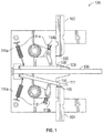
- ATS switch housing or cassette 100 includes a first source bar 102 with a first source contact pad 103, a second source bar 104 with a second source contact pad 105, a stationary bar 106, a first movable bar 108 with a first movable contact pad 109, a second movable bar 110 with a second movable contact pad 111, a first spring and mechanical linkage 114, and a second spring and mechanical linkage 116.
- the first source bar 102 and the second source bar 104 are fixed on the cassette 100.
- the first source bar 102 may be connected to a primary power source (not illustrated in the present figure), for example, a utility.
- the second source bar 104 may be coupled to a secondary power source (not illustrated in the present figure), for example, a generator.
- the stationary bar 106 is also fixed on the cassette 100.
- the stationary bar 106 may be coupled to an electrical load (not illustrated in the present figure), for example, a resistive load and/or a motor load.
- the load may include appliances, lights, or other loads desirable to power in the event of a utility grid failure.
- stationary bar 106 is a T-shaped bar.
- the first movable bar 108 and the second movable bar 110 are each electrically coupled and rotatably connected to the stationary bar 106.
- the first and second movable bars 108 and 110 each rotate between a closed position and an open position.
- the "closed position” refers to the situation in which the movable bar engages the corresponding source bar of the power source that supplies power.
- the "open position” refers to the situation in which the movable bar disengages the corresponding source bar of the power source that is disconnected from the load.
- the first movable contact pad 109 at an end of the first movable bar 108 engages the first source contact pad 103 at an end of the first source contact 102.
- the first movable bar 108 is in the closed position and the electrical load is electrically connected to the primary power source.
- the first movable bar 108 rotates from the closed position to the open position to disengage the first movable contact pad 109 from the first source contact pad 103.
- the second movable bar 110 rotates from the open position to the closed position to allow the second movable contact pad 111 at an end of the second movable bar 110 to engage the second source contact pad 105 at an end of the second source contact 104.
- the electrical load is electrically connected to the secondary power source. A similar operation is performed to transfer back to the primary power source from the secondary power source when the interruption is over.
- the contacts pads 103, 105, 109, and 111 are made of a silver or copper alloy.
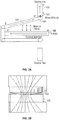
- FIG. 2A schematic diagram of blow-on and blow-off forces on a movable bar of the automatic transfer switch of FIG. 1 is shown in a closed position.
- the current flow path is A-A' in the stationary bar 106, B-B' in the first movable bar 108, and C-C' in the first source contact 102. Since the current flow directions are opposite in the stationary bar 106 and the first movable bar 108, an repulsive electromagnetic force is induced that pushes the first movable bar 108 away from the stationary bar 106. This is the blow-on force that biases the first movable contact pad 109 towards the first source contact pad 103 and assists the closing force provided by the first spring and mechanical linkage 114.
- FIG. 2B illustrates current flowing through the first movable contact pad 109 and the first source contact pad 103.
- the in and out currents between the first movable contact pad 109 and the first source contact pad 103 are not on the same axis but form an angle.
- the in current and the out current induce a repulsive electromagnetic force between the first movable contact pad 109 and the first source contact pad 103 which pushes the first movable contact pad 109 away from the first source contact pad 103. This is a blow-off force that separates the contacts apart.
- the cassette 100 may further include springs to help maintain a contact force during operation.
- the first spring and mechanical linkage 114 includes a spring 114a that pulls from the bottom of the first movable bar 108 and a spring 114b that presses on top of the first movable bar 108.
- the second spring and mechanical linkage 116 includes a spring 116a that pulls from the bottom of the second movable bar 110 and a spring 116b that presses on top of the second movable bar 110.
- springs 114a and 114b can be combined into a single spring 114, and so can springs 116a and 116b.
- the first spring and mechanical linkage 114 and the second spring and mechanical linkage 116 each apply about 10 N to 100 N contact force on the corresponding movable bar at the closed position.
- FIG. 3 a schematic diagram of a system 300 of coupled blow-on force automatic transfer switches 310 and 320 in a daisy-chain configuration is shown according to an exemplary embodiment.
- the system 300 includes a first automatic transfer switch 310 and a second automatic transfer switch 320 coupled together. It shall be appreciated that the system of two switches is given herein for example only, not for limitation.
- the system 300 may include any number of coupled switches.
- the system 300 may be used, for example, as a bypass configuration of switches for critical power installations. In the bypass configuration, two or more automatic transfer switches are coupled in parallel and driven by a common controller. If one automatic transfer switch fails, it can be automatically bypassed by the other automatic transfer switches.
- the automatic transfer switches are connected in a manner that is at the convenience of the physical implementation without considering current paths in the switches.
- the current in the switch needs to follow the appropriate path through each switch, for example, from the distal ends 317 and 327 of the stationary bars 313 and 323 and through the connection ends 316 and 326 of the stationary bars 313 and 323 to the first movable bar 314 and 324 or to the second movable bars 315 and 325.
- the induced electromagnetic force biases the selected movable bar having the current flowing through them towards their respective source bar contact, for example, first movable bars 314 and 324 towards the first source bars 311 and 321. If the current does not follow the proper path, the benefits of the design would be lost.
- the system 300 maintains the proper current path for both automatic transfer switches 310 and 320 that are coupled together.
- Clusters 330 are removable electrical connections that can electrically connect between two bus bars or cables in an ATS or switch gear cabinet or other installation for the ATS switches 310 and 320.
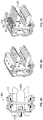
- FIG. 4 a cluster 400 is shown according to an exemplary embodiment.
- One bus bar can be mechanically mounted at one side 410 of the cluster 400.
- Another bus bar can be inserted between the arms 420 and pressed by springs 430 against the arms 420. In this manner, an electrical connection can be formed between the bus bars.
- FIG. 5 shows an assembly of four clusters 510, 520, 530, and 540 that can provide multiple electrical connections. It is noted that other electrical connections, bus bars, and/or cabling arrangements can be utilized in various embodiments, and all such alternatives are contemplated within the scope of the present disclosure.
- the first switch 310 includes, among others, a first source bar 311 , a second source bar 312, a stationary bar 313, a first movable bar 314, and a second movable bar 315.
- the stationary bar 313 has a front or movable bar connection end 316 and a back or distal end 317.
- the first movable bar 314 and the second movable bar 315 are each connected to the stationary bar 313 at the front end 316.
- the back end 317 of the stationary bar 313 may be connected to an electrical load.
- the second switch 320 has similar components as the first switch 310, i.e., a first source bar 321, a second source bar 322, a stationary bar 323 with a front end 326 and a back end 327, a first movable bar 324, and a second movable bar 325.
- the first source bar 311 of the first switch 310 is connected to the first source bar 321 of the second switch 320.
- the second source bar 312 of the first switch 310 is connected to the second source bar 322 of the second switch 320.
- the system 300 may be used in a multiple source daisy chained configuration where each source bar connects to a different source to allow for more than two sources to be selected from under control of the daisy chained ATS switches 310 and 320.
- the first source bars 311 and 321 and second source bars 312 and 322 would not be coupled in parallel, but connected to separate different sources.
- the first source bar 311 of the first switch 310 is associated with a main utility
- the second source bar 312 of the first switch 310 is associated with a second utility
- the first source bar 321 of the second switch 320 is associated with a generator as a backup power.
- the back end 317 of the stationary bar 313 of the first switch 310 is connected to the front end 326 of the stationary bar 323 of the second switch 320.
- proper current flow path is preserved through the stationary bars 313 and 323 for each of the first and second switches 310 and 320 to allow for the blow-on EMF force to be generated during operation.
- the current flow path would be the same path as shown in FIG. 2A , which is A-A' in the stationary bar and B-B' in the first movable bar.
- the system 300 may be used in the by-pass configuration where the first source bar 311 of the first switch 310 and the first source bar 321 of the second switch 320 are connected to a same first power source (not shown in the present figures).
- the second source bar 312 of the first switch 310 and the second source bar 322 of the second switch 320 are connected to a same second power source.
- the first switch 310 and the second switch 320 may be on a same cartridge, or on different cartridges.
- FIG. 6 a schematic diagram of a system 600 of coupled automatic transfer switches having source connections on a single side is shown according to the invention.
- the system 600 includes a first single sided blow-on automatic transfer switch 610, a second single sided blow-on automatic transfer switch 620, and a third single sided blow-on automatic transfer switch 630 sharing a stationary bar 640.
- the system 600 may include any appropriate number of coupled switches. It is noted that two single sided switches daisy chained as shown in FIG. 6 can be an equivalent of a single two source, double sided ATS switch, such as those illustrated in FIGS. 1-3 .
- each of the switches 610, 620, and 630 is a "single-sided" switch, i.e., each switch has a source contact on only one side, as opposing to the "double-sided” switches shown in FIG. 3 .
- the singled-sided design allows for lower overall profile and increased cooling at the expense of some additional length.
- the increased cartridge external surface area and potential exposure of and/or addition of heat sinks on the back side of the source bars 611, 621, and 631 can take heat away from the movable bar and source contact.
- the first switch 610 has a source bar 611 that may be connected to a first power source (not illustrated in the present figure).
- the second switch 620 has a source bar 621 that may be connected to a second power source (not illustrated in the present figure).
- the third switch 630 has a source bar 631 that may be connected to a third power source (not illustrated in the present figure).
- the first, second, and third power sources are different.
- the first power source may be a main utility
- the second power source may be a second utility
- the third power source may be a backup power such as a generator.
- two or more of the power sources may be the same type of switch and may be used in parallel in a redundant bypass configuration (e.g., two of the three power sources are the same and the other one is different, all three are the same, etc.).
- FIG. 7 shows an example three-pole ATS 700.
- Bus bars 710 are used for dissipating heat, which add to 30% cost and 20% weight of the ATS. By using the low-profile design illustrated in FIG. 6 , long bus bars like 710 may not be needed due to better heat dissipation.
- the thickness of the ATS may be reduced to, for example, about 400 mm or less. It is noted that for the three source bypass configuration with main utility, second utility, and backup generator, one long single sided daisy chain may be used, two single sided daisy chains operating in parallel may be used, or, a single daisy chain of double sided blow-on switches with a different switching pattern may be used. A large parallel implementation with single/double sided blow-on switches (i.e., every switch coupled in parallel at the back or distal end to the load and the sources in parallel, or coupled to different sources) is also possible.
- the first switch 610 includes a movable bar 612 electrically coupled and rotatably connected to the stationary bar 640.
- the movable bar 612 is connected to the stationary bar 640 at a front end 613 of the first switch 610.
- the source bar 611 is disposed at a back end 614 of the first switch 610.
- the second switch 620 includes a movable bar 622 similar to the movable bar 612, a front end 623 where the movable bar 620 is connected to the stationary bar 640, and a back end 624 where a source bar 622 is disposed at.
- the third switch 630 includes a movable bar 632 similar to the movable bar 612, a front end 633 where the movable bar 630 is connected to the stationary bar 640, and a back end 634 where a source bar 632 is disposed at.
- the stationary bar 640 may be connected to an electrical load at the back end 634 of the third switch 630.
- proper current flow path is preserved from the back end of the stationary bar through the movable bar to the source bar to generate the blow-on force EMF for each of the first switch 610, the second switch 620, and the third switch 630. If the electrical load is connected to the power source via the first switch 610, the current flow path would be the same path as shown in FIG.
- blow-on force design can be preserved for multiple automatic transfer switches coupled on a single cassette or by a daisy chain.
- one housing couples multiple source terminals to a stationary bar.
- two or more source terminals on separate cassettes are coupled together, for example, via a "cluster" connector on the stationary bar.
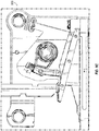
- FIG. 8A shows an anti-bounce blow-on contact ATS cassette 800 at an open position.
- FIG. 8B shows the anti-bounce blow-on contact ATS cassette 800 at an initial closed position.
- the cassette 800 includes a source bar 802 with a source contact pad 803, a stationary bar 806, a movable bar 808 with a movable contact pad 809, a movable linkage 814, a T-shaped linkage 815, a spring 816, a cam 817 with a hex bar 818.
- the source bar 802, the stationary bar 806, and the movable bar 808 may have similar structures as the corresponding components discussed with reference to FIG. 1
- the cam 817 is rotatably mounted on the cassette 800.
- the movable bar 808 is linked to the cam 817 through the movable linkage 814, which is coupled to the cam 817 through a slot 811.
- the spring 816 is wound around the T-shaped linkage 815 and coupled to the cam 817.
- the cam 817 can rotate along the T-shaped linkage 815 when the spring 816 is compressed.
- the hex bar 818 is formed within the cam 817.
- the hex bar 818 Upon closing, the hex bar 818 is driven to rotate, which drives the cam 817 to rotate.
- the rotation of the cam 817 pulls the movable bar 808 up to the initial closed position where the movable contact pad 809 is just in contact with the source contact pad 803.
- the spring 816 At the initial position, the spring 816 is substantially not compressed and has a length of P1.
- the contact pads 809 and 803 are closed at the initial position, the movement of the movable bar 808 and of the movable linkage 814 is impeded by the source bar 802.
- the clam 817 rotates along the T-shaped linkage 815 and gradually compresses the spring 816 until an ultimate closed position is reached.
- the spring 816 is compressed and has a length of P2 shorter than P1.
- the contact force between the contact pads 809 and 803 gradually increases. The initial lower contact force followed by a gradual increase of contact force helps minimize bounce back of the contact pads 809 and 803 upon closing.
Landscapes
- Engineering & Computer Science (AREA)
- Power Engineering (AREA)
- Physics & Mathematics (AREA)
- Electromagnetism (AREA)
- Business, Economics & Management (AREA)
- Emergency Management (AREA)
- Keying Circuit Devices (AREA)
- Driving Mechanisms And Operating Circuits Of Arc-Extinguishing High-Tension Switches (AREA)
Claims (14)
- Système (600) de commutateurs de transfert automatique couplés, le système comprenant :une barre fixe (640) ; etune pluralité de commutateurs de transfert automatique (610, 620, 630), chaque commutateur de la pluralité de commutateurs de transfert automatique comprenant :une barre de source (611, 621, 631) structurée pour se connecter à une source d'énergie correspondante ; etune barre mobile (612, 622, 632) couplée électriquement et connectée de manière rotative à la barre fixe (640), où la barre mobile (612) entre en contact avec la barre de source pour fournir de l'énergie à partir de la source d'énergie correspondante, où la barre mobile est soumise à une force électromagnétique polarisant la barre mobile (612) vers la barre de source (611), et où la force électromagnétique est induite par du courant circulant à travers la barre fixe (640) et la barre mobile ;caractérisé en ce que la pluralité de commutateurs de transfert automatique (610, 620, 630) sont sur la barre fixe (640), et en ce que les barres mobiles (612, 622, 632) de la pluralité de commutateurs de transfert automatique sont disposées d'un même côté de la barre fixe.
- Système selon la revendication 1, où la barre fixe (640) est formée de plusieurs sections reliées entre elles.
- Système selon l'une quelconque des revendications précédentes, où chaque commutateur de la pluralité de commutateurs de transfert automatique (610, 620, 630) a une extrémité avant (613, 623, 633) et une extrémité arrière (614, 624, 634), où la barre mobile correspondante (612, 622, 632) est connectée à la barre fixe (640) au niveau de l'extrémité avant (613, 623, 633) et la barre de source correspondante (611, 621, 631) est disposée au niveau de l'extrémité arrière (614, 624, 634), et où la pluralité de commutateurs de transfert automatique (610, 620, 630) est disposée sur la barre fixe (640) de telle sorte qu'une direction de l'extrémité avant (613, 623, 633) vers l'extrémité arrière (614, 624, 634) est la même pour chaque commutateur de la pluralité de commutateurs de transfert automatique.
- Système selon l'une quelconque des revendications précédentes, où la barre de source (611) d'un premier commutateur de transfert automatique (610) et la barre de source (621) d'un deuxième commutateur de transfert automatique (620) sont connectées à une même source d'énergie, et où un commutateur parmi le premier commutateur de transfert automatique et le deuxième commutateur de transfert automatique maintient une transmission d'énergie en cas de défaillance de l'autre commutateur parmi le premier commutateur de transfert automatique et le deuxième commutateur de transfert automatique.
- Système selon l'une quelconque des revendications précédentes, où chaque barre des barres de source (611, 621, 631) de la pluralité de commutateurs de transfert automatique (610, 620, 630) est configurée pour se connecter à une source d'énergie différente, et où une barre mobile (612, 622, 632) est en contact avec la barre de source correspondante (611, 621, 631) à la fois.
- Système selon l'une quelconque des revendications précédentes, où au moins un commutateur de la pluralité de commutateurs de transfert automatique (610, 620, 630) comprend une liaison mobile (814), une liaison en forme de T (815), un ressort (816), et une came (817) avec une barre hexagonale (818), où la première barre mobile (808) est reliée à la came par la liaison mobile, où le ressort est enroulé autour de la liaison en forme de T et couplé à la came, où la barre hexagonale est structurée pour faire tourner la came d'une position fermée initiale vers une position fermée finale, où, dans la position fermée initiale, la première barre mobile entre en contact avec la première barre de source (802), le ressort n'est sensiblement pas comprimé, et où, dans la position fermée finale, la première barre mobile est pressée contre la première barre de source et le ressort est comprimé.
- Système (300) selon l'une quelconque des revendications précédentes, le système comprenant :un premier commutateur de transfert automatique (310) et un deuxième commutateur de transfert automatique (320) couplés selon une configuration en parallèle, chaque commutateur parmi le premier commutateur de transfert automatique et le deuxième commutateur de transfert automatique comprenant :une première barre de source (311, 321) structurée pour se connecter à une première source d'énergie ;une deuxième barre de source (312, 322) structurée pour se connecter à une deuxième source d'énergie ;une barre fixe (313, 323) avec une partie avant (316, 326) et une partie arrière (317, 327) ;une première barre mobile (314, 324) couplée électriquement et connectée de manière rotative à la barre fixe au niveau de l'extrémité avant, où la première barre mobile entre en contact avec la première barre de source pour fournir de l'énergie à partir de la première source d'énergie, où la première barre mobile est soumise à une première force électromagnétique polarisant la première barre mobile vers la première barre de source, et où la première force électromagnétique est induite par du courant circulant à travers la barre fixe et la première barre mobile ; etune deuxième barre mobile (315, 325) couplée électriquement et connectée de manière rotative à la barre fixe au niveau de l'extrémité avant, où la deuxième barre mobile entre en contact avec la deuxième barre de source pour fournir de l'énergie à partir de la deuxième source d'énergie, où la deuxième barre mobile est soumise à une deuxième force électromagnétique polarisant la deuxième barre mobile vers la deuxième barre de source, et où la deuxième force électromagnétique est induite par du courant circulant à travers la barre fixe et la deuxième barre mobile ;où l'extrémité arrière (317) de la barre fixe (313) du premier commutateur de transfert automatique (310) est connectée à l'extrémité avant (326) de la barre fixe (323) du deuxième commutateur de transfert automatique (320).
- Système selon la revendication 7, où la première barre de source (311) du premier commutateur de transfert automatique (310) est connectée à la première barre de source (321) du deuxième commutateur de transfert automatique (320), et où la deuxième barre de source (312) du premier commutateur de transfert automatique (310) est connectée à la deuxième barre de source (322) du deuxième commutateur de transfert automatique (320).
- Système selon la revendication 7 ou 8, où :un commutateur parmi le premier commutateur de transfert automatique (310) ou le deuxième commutateur de transfert automatique (320) maintient une transmission d'énergie en cas de défaillance de l'autre commutateur parmi le premier commutateur de transfert automatique ou le deuxième commutateur de transfert automatique ;le premier commutateur de transfert automatique est couplé au deuxième commutateur de transfert automatique par l'intermédiaire de grappes (330) ; et/oul'extrémité arrière (327) du deuxième commutateur de transfert automatique est structurée pour se connecter à une charge électrique.
- Système selon l'une quelconque des revendications 7 à 9, comprenant en outre :une cartouche sur laquelle sont disposés le premier commutateur de transfert automatique et le deuxième commutateur de transfert automatique, ouune première cartouche sur laquelle est disposé le premier commutateur de transfert automatique et une deuxième cartouche sur laquelle est disposé le deuxième commutateur de transfert automatique.
- Système selon l'une quelconque des revendications 7 à 10, où au moins un commutateur parmi le premier commutateur de transfert automatique ou le deuxième commutateur de transfert automatique comprend un ressort (816) structuré pour augmenter la compression entre la première barre mobile et la première barre de source en position fermée pour empêcher le rebond de contact.
- Système selon la revendication 11, où au moins un commutateur parmi le premier commutateur de transfert automatique ou le deuxième commutateur de transfert automatique comprend en outre une liaison mobile (814), une liaison en forme de T (815), et une came (817) avec une barre hexagonale (818), où la première barre mobile est reliée à la came par la liaison mobile, où le ressort est enroulé autour de la liaison en forme de T et couplé à la came, où la barre hexagonale est structurée pour faire tourner la came d'une position fermée initiale vers une position fermée finale, où, dans la position fermée initiale, la première barre mobile entre en contact avec la première barre de source, le ressort n'est sensiblement pas comprimé, et où, dans la position fermée finale, la première barre mobile est pressée contre la première barre de source et le ressort est comprimé.
- Système comprenant :le système de commutateurs de transfert automatique couplés selon l'une quelconques des revendications précédentes ; etun générateur couplé à au moins une barre parmi la deuxième barre de source du premier commutateur de transfert automatique ou la deuxième barre de source du deuxième commutateur de transfert automatique et structuré pour transmettre de l'énergie électrique sur au moins une barre parmi la deuxième barre de source du premier commutateur de transfert automatique ou la deuxième barre de source du deuxième commutateur de transfert automatique.
- Système selon la revendication 13, où au moins une barre parmi la première barre de source du premier commutateur de transfert automatique ou la première barre de source du deuxième commutateur de transfert automatique est structurée pour se connecter à un réseau électrique.
Applications Claiming Priority (2)
| Application Number | Priority Date | Filing Date | Title |
|---|---|---|---|
| US201562245753P | 2015-10-23 | 2015-10-23 | |
| PCT/US2016/058288 WO2017070592A1 (fr) | 2015-10-23 | 2016-10-21 | Commutateur automatique profil bas à force de soufflage |
Publications (3)
| Publication Number | Publication Date |
|---|---|
| EP3365905A1 EP3365905A1 (fr) | 2018-08-29 |
| EP3365905A4 EP3365905A4 (fr) | 2019-05-01 |
| EP3365905B1 true EP3365905B1 (fr) | 2021-03-10 |
Family
ID=58558159
Family Applications (1)
| Application Number | Title | Priority Date | Filing Date |
|---|---|---|---|
| EP16858380.5A Active EP3365905B1 (fr) | 2015-10-23 | 2016-10-21 | Commutateur automatique profil bas à force de soufflage |
Country Status (4)
| Country | Link |
|---|---|
| US (2) | US10163585B2 (fr) |
| EP (1) | EP3365905B1 (fr) |
| CN (1) | CN108140500B (fr) |
| WO (1) | WO2017070592A1 (fr) |
Families Citing this family (10)
| Publication number | Priority date | Publication date | Assignee | Title |
|---|---|---|---|---|
| EP3365905B1 (fr) * | 2015-10-23 | 2021-03-10 | Cummins Power Generation IP, Inc. | Commutateur automatique profil bas à force de soufflage |
| CN108352265B (zh) * | 2015-10-23 | 2019-10-29 | 康明斯发电Ip公司 | 平衡力吹气式接触自动转换开关 |
| US10148072B2 (en) * | 2016-02-17 | 2018-12-04 | Asco Power Technologies, L.P. | Methods and systems for autonomous redundant control |
| WO2019079582A1 (fr) | 2017-10-19 | 2019-04-25 | Cummins Power Generation Ip, Inc. | Équilibrage de courant pour commutateurs de transfert automatique |
| US10644536B2 (en) * | 2017-11-28 | 2020-05-05 | Cummins Power Generation Ip, Inc. | Cooling systems and methods for automatic transfer switch |
| US11244799B2 (en) | 2018-11-27 | 2022-02-08 | Cummins Power Generation Ip, Inc. | Four-way automatic transfer switch |
| EP3671783A1 (fr) * | 2018-12-20 | 2020-06-24 | ABB Schweiz AG | Ensemble de contact conçu pour interrupteur coupe-charge, interrupteur coupe-charge et procédé de fermeture d'un trajet de circuit d'un ensemble de contact |
| US12074002B2 (en) * | 2019-06-21 | 2024-08-27 | Cummins Power Generation Ip, Inc. | Flat force blow-on switch |
| WO2022076066A1 (fr) * | 2020-10-08 | 2022-04-14 | Generac Power Systems, Inc. | Commutateur de transfert à wcr élevé |
| CN115798968B (zh) * | 2022-11-22 | 2025-12-19 | 苏州飞腾电器有限公司 | 三电源人防转换开关 |
Family Cites Families (31)
| Publication number | Priority date | Publication date | Assignee | Title |
|---|---|---|---|---|
| US2601422A (en) * | 1947-01-07 | 1952-06-24 | Ite Circuit Breaker Ltd | Circuit breaker |
| US4021678A (en) * | 1976-01-19 | 1977-05-03 | Automatic Switch Company | Automatic transfer switch |
| US4157461A (en) * | 1977-10-19 | 1979-06-05 | Automatic Switch Company | Automatic transfer switch and bypass switch arrangement |
| US4168407A (en) * | 1977-11-23 | 1979-09-18 | Automatic Switch Company | Electrical switch assembly including a separate interrupter switch |
| US4405867A (en) * | 1980-01-23 | 1983-09-20 | Automatic Switch Company | System for transferring a load between two power sources without interruption of power to the load |
| US4423336A (en) * | 1982-05-17 | 1983-12-27 | Mcgraw-Edison Company | Electromechanically controlled automatic transfer switch and bypass switch assembly |
| US5077485A (en) | 1989-11-06 | 1991-12-31 | Sundstrand Corporation | Voltage regulator load division using real and reactive generator output power components to control the exciter |
| US5070252A (en) * | 1990-04-03 | 1991-12-03 | Automatic Switch Company | Automatic transfer switch |
| US5081367A (en) * | 1990-07-06 | 1992-01-14 | Westinghouse Electric Corp. | Electric power system with maintenance bypass for uninterruptible power supply using closed transition operation |
| US5200586A (en) * | 1991-07-31 | 1993-04-06 | Westinghouse Electric Corp. | Five gear isolating mechanism for bypass isolation switches |
| US5581133A (en) * | 1993-12-17 | 1996-12-03 | Eaton Corporation | Combination transfer and bypass isolation switch utilizing drawout protective devices and key interlocks |
| US6919518B2 (en) | 2002-02-19 | 2005-07-19 | Onan Corporation | Phase flux barriers for transfer switch |
| US6534737B1 (en) * | 2002-02-19 | 2003-03-18 | Onan Corporation | Contact closing speed limiter for a transfer switch |
| KR100421982B1 (ko) | 2002-05-31 | 2004-03-11 | 삼성전자주식회사 | 수직 얼라인먼트의 보정이 가능한 화상형성장치 및 그의보정방법 |
| US6765157B2 (en) * | 2002-07-24 | 2004-07-20 | Onan Corporation | Transfer switch with improved actuator |
| US6700087B2 (en) * | 2002-07-24 | 2004-03-02 | Onan Corporation | Arc chute assembly |
| US7091702B2 (en) | 2004-12-07 | 2006-08-15 | Hamilton Sundstrand Corporation | Digital real and reactive load division control |
| US6995327B1 (en) * | 2005-04-11 | 2006-02-07 | Eaton Corporation | Four-way interlock system and bypass transfer switch employing the same |
| GB0510666D0 (en) | 2005-05-25 | 2005-06-29 | Newage Int Ltd | Control system |
| KR20090084111A (ko) | 2008-01-31 | 2009-08-05 | 성일휴 | 자동전환 스위치 |
| US8471659B1 (en) * | 2008-03-05 | 2013-06-25 | Reliance Controls Corporation | Automatic transfer switch having an interlock arrangement |
| US8138861B2 (en) * | 2009-05-15 | 2012-03-20 | Eaton Corporation | Inertial catch for an automatic transfer switch power contractor |
| US8242394B2 (en) * | 2010-02-12 | 2012-08-14 | Eaton Corporation | Stationary contact assembly including first and second stationary contacts, and circuit interrupter and transfer switch employing the same |
| US20120205986A1 (en) | 2010-09-01 | 2012-08-16 | Kohler Co. | Multiple single phase generator configuration |
| US8604377B2 (en) * | 2011-07-15 | 2013-12-10 | Vitzrotech Co., Ltd | Automatic transfer switch |
| CN202443868U (zh) * | 2012-02-29 | 2012-09-19 | 环宇集团有限公司 | 双电源自动转换开关 |
| US9142365B2 (en) * | 2013-02-15 | 2015-09-22 | Ward Leonard Investment Holdings, LLC | Solenoid-driven automatic transfer switch |
| US8830018B1 (en) * | 2013-02-15 | 2014-09-09 | Ward Leonard Investment Holdings, LLC | Solenoid-driven automatic transfer switch |
| US9368295B2 (en) * | 2013-02-27 | 2016-06-14 | General Electric Company | Electrical transfer switch system |
| WO2015131042A2 (fr) * | 2014-02-28 | 2015-09-03 | Wal-Mart Stores, Inc. | Armoire de mise hors service pour entretien à commutateur de transfert automatique |
| EP3365905B1 (fr) * | 2015-10-23 | 2021-03-10 | Cummins Power Generation IP, Inc. | Commutateur automatique profil bas à force de soufflage |
-
2016
- 2016-10-21 EP EP16858380.5A patent/EP3365905B1/fr active Active
- 2016-10-21 CN CN201680061678.8A patent/CN108140500B/zh active Active
- 2016-10-21 WO PCT/US2016/058288 patent/WO2017070592A1/fr not_active Ceased
- 2016-10-21 US US15/331,660 patent/US10163585B2/en active Active
-
2018
- 2018-11-29 US US16/204,203 patent/US11501930B2/en active Active
Non-Patent Citations (1)
| Title |
|---|
| None * |
Also Published As
| Publication number | Publication date |
|---|---|
| US11501930B2 (en) | 2022-11-15 |
| EP3365905A1 (fr) | 2018-08-29 |
| US20170117104A1 (en) | 2017-04-27 |
| US10163585B2 (en) | 2018-12-25 |
| EP3365905A4 (fr) | 2019-05-01 |
| CN108140500A (zh) | 2018-06-08 |
| CN108140500B (zh) | 2019-10-29 |
| US20190096595A1 (en) | 2019-03-28 |
| WO2017070592A1 (fr) | 2017-04-27 |
Similar Documents
| Publication | Publication Date | Title |
|---|---|---|
| US11501930B2 (en) | Low profile blow-on force automatic switch | |
| CN101303946B (zh) | 电气开关装置及其导体组件和分流器组件 | |
| EP2251881A2 (fr) | Fermeture inertielle de contacteur d'alimentation de commutateur de transfert automatique | |
| US9530578B2 (en) | Electrical switching apparatus and transmission assembly therefor | |
| US11764018B2 (en) | System of four way automatic transfer switches | |
| US8242394B2 (en) | Stationary contact assembly including first and second stationary contacts, and circuit interrupter and transfer switch employing the same | |
| US5351024A (en) | Electrical contactor and interrupter employing a rotary disc | |
| EP1988558A1 (fr) | Appareil de commutation électrique, et assemblage de fourche et son ensemble de ressort | |
| CN118588501A (zh) | 多开关接触器总成 | |
| EP2485229B1 (fr) | Dérivation flexible pour disjoncteur sous vide | |
| CA2894939C (fr) | Appareil de commutation electrique et ensemble liaison pour celui-ci | |
| EP1346385B1 (fr) | Disjoncteur de limitation de courant automatique | |
| CN113745066A (zh) | 分励脱扣器 | |
| KR20170108657A (ko) | 직류 차단기 | |
| CN101136292B (zh) | 开关装置 | |
| US9172170B2 (en) | Bus connector with reduced insertion force | |
| EP3776619B1 (fr) | Conducteur flexible pour sectionneur et sectionneur associé | |
| US9613763B2 (en) | Circuit breakers with secondary displacement springs | |
| GB2465604A (en) | Snap action electrical disconnector |
Legal Events
| Date | Code | Title | Description |
|---|---|---|---|
| STAA | Information on the status of an ep patent application or granted ep patent |
Free format text: STATUS: THE INTERNATIONAL PUBLICATION HAS BEEN MADE |
|
| PUAI | Public reference made under article 153(3) epc to a published international application that has entered the european phase |
Free format text: ORIGINAL CODE: 0009012 |
|
| STAA | Information on the status of an ep patent application or granted ep patent |
Free format text: STATUS: REQUEST FOR EXAMINATION WAS MADE |
|
| 17P | Request for examination filed |
Effective date: 20180417 |
|
| AK | Designated contracting states |
Kind code of ref document: A1 Designated state(s): AL AT BE BG CH CY CZ DE DK EE ES FI FR GB GR HR HU IE IS IT LI LT LU LV MC MK MT NL NO PL PT RO RS SE SI SK SM TR |
|
| AX | Request for extension of the european patent |
Extension state: BA ME |
|
| DAV | Request for validation of the european patent (deleted) | ||
| DAX | Request for extension of the european patent (deleted) | ||
| A4 | Supplementary search report drawn up and despatched |
Effective date: 20190402 |
|
| RIC1 | Information provided on ipc code assigned before grant |
Ipc: H01H 3/60 20060101ALI20190327BHEP Ipc: H01H 15/08 20060101ALI20190327BHEP Ipc: H01H 5/06 20060101ALI20190327BHEP Ipc: H01H 15/06 20060101ALI20190327BHEP Ipc: H01H 3/56 20060101ALI20190327BHEP Ipc: H01H 3/40 20060101AFI20190327BHEP Ipc: H01H 1/22 20060101ALI20190327BHEP Ipc: H01H 77/10 20060101ALI20190327BHEP Ipc: H01H 3/22 20060101ALI20190327BHEP Ipc: H01H 5/04 20060101ALI20190327BHEP |
|
| GRAP | Despatch of communication of intention to grant a patent |
Free format text: ORIGINAL CODE: EPIDOSNIGR1 |
|
| STAA | Information on the status of an ep patent application or granted ep patent |
Free format text: STATUS: GRANT OF PATENT IS INTENDED |
|
| RIC1 | Information provided on ipc code assigned before grant |
Ipc: H01H 15/06 20060101ALI20200824BHEP Ipc: H01H 3/40 20060101AFI20200824BHEP Ipc: H01H 1/22 20060101ALI20200824BHEP Ipc: H01H 3/56 20060101ALI20200824BHEP Ipc: H01H 15/08 20060101ALI20200824BHEP Ipc: H01H 77/10 20060101ALI20200824BHEP Ipc: H01H 3/60 20060101ALI20200824BHEP Ipc: H01H 5/04 20060101ALI20200824BHEP Ipc: H01H 5/06 20060101ALI20200824BHEP Ipc: H01H 3/22 20060101ALI20200824BHEP |
|
| INTG | Intention to grant announced |
Effective date: 20200924 |
|
| GRAS | Grant fee paid |
Free format text: ORIGINAL CODE: EPIDOSNIGR3 |
|
| GRAA | (expected) grant |
Free format text: ORIGINAL CODE: 0009210 |
|
| STAA | Information on the status of an ep patent application or granted ep patent |
Free format text: STATUS: THE PATENT HAS BEEN GRANTED |
|
| AK | Designated contracting states |
Kind code of ref document: B1 Designated state(s): AL AT BE BG CH CY CZ DE DK EE ES FI FR GB GR HR HU IE IS IT LI LT LU LV MC MK MT NL NO PL PT RO RS SE SI SK SM TR |
|
| REG | Reference to a national code |
Ref country code: GB Ref legal event code: FG4D |
|
| REG | Reference to a national code |
Ref country code: AT Ref legal event code: REF Ref document number: 1370736 Country of ref document: AT Kind code of ref document: T Effective date: 20210315 Ref country code: CH Ref legal event code: EP |
|
| REG | Reference to a national code |
Ref country code: DE Ref legal event code: R096 Ref document number: 602016054204 Country of ref document: DE |
|
| REG | Reference to a national code |
Ref country code: IE Ref legal event code: FG4D |
|
| REG | Reference to a national code |
Ref country code: LT Ref legal event code: MG9D |
|
| PG25 | Lapsed in a contracting state [announced via postgrant information from national office to epo] |
Ref country code: NO Free format text: LAPSE BECAUSE OF FAILURE TO SUBMIT A TRANSLATION OF THE DESCRIPTION OR TO PAY THE FEE WITHIN THE PRESCRIBED TIME-LIMIT Effective date: 20210610 Ref country code: FI Free format text: LAPSE BECAUSE OF FAILURE TO SUBMIT A TRANSLATION OF THE DESCRIPTION OR TO PAY THE FEE WITHIN THE PRESCRIBED TIME-LIMIT Effective date: 20210310 Ref country code: HR Free format text: LAPSE BECAUSE OF FAILURE TO SUBMIT A TRANSLATION OF THE DESCRIPTION OR TO PAY THE FEE WITHIN THE PRESCRIBED TIME-LIMIT Effective date: 20210310 Ref country code: GR Free format text: LAPSE BECAUSE OF FAILURE TO SUBMIT A TRANSLATION OF THE DESCRIPTION OR TO PAY THE FEE WITHIN THE PRESCRIBED TIME-LIMIT Effective date: 20210611 Ref country code: LT Free format text: LAPSE BECAUSE OF FAILURE TO SUBMIT A TRANSLATION OF THE DESCRIPTION OR TO PAY THE FEE WITHIN THE PRESCRIBED TIME-LIMIT Effective date: 20210310 Ref country code: BG Free format text: LAPSE BECAUSE OF FAILURE TO SUBMIT A TRANSLATION OF THE DESCRIPTION OR TO PAY THE FEE WITHIN THE PRESCRIBED TIME-LIMIT Effective date: 20210610 |
|
| REG | Reference to a national code |
Ref country code: AT Ref legal event code: MK05 Ref document number: 1370736 Country of ref document: AT Kind code of ref document: T Effective date: 20210310 |
|
| REG | Reference to a national code |
Ref country code: NL Ref legal event code: MP Effective date: 20210310 |
|
| PG25 | Lapsed in a contracting state [announced via postgrant information from national office to epo] |
Ref country code: SE Free format text: LAPSE BECAUSE OF FAILURE TO SUBMIT A TRANSLATION OF THE DESCRIPTION OR TO PAY THE FEE WITHIN THE PRESCRIBED TIME-LIMIT Effective date: 20210310 Ref country code: RS Free format text: LAPSE BECAUSE OF FAILURE TO SUBMIT A TRANSLATION OF THE DESCRIPTION OR TO PAY THE FEE WITHIN THE PRESCRIBED TIME-LIMIT Effective date: 20210310 Ref country code: LV Free format text: LAPSE BECAUSE OF FAILURE TO SUBMIT A TRANSLATION OF THE DESCRIPTION OR TO PAY THE FEE WITHIN THE PRESCRIBED TIME-LIMIT Effective date: 20210310 |
|
| PG25 | Lapsed in a contracting state [announced via postgrant information from national office to epo] |
Ref country code: NL Free format text: LAPSE BECAUSE OF FAILURE TO SUBMIT A TRANSLATION OF THE DESCRIPTION OR TO PAY THE FEE WITHIN THE PRESCRIBED TIME-LIMIT Effective date: 20210310 |
|
| PG25 | Lapsed in a contracting state [announced via postgrant information from national office to epo] |
Ref country code: CZ Free format text: LAPSE BECAUSE OF FAILURE TO SUBMIT A TRANSLATION OF THE DESCRIPTION OR TO PAY THE FEE WITHIN THE PRESCRIBED TIME-LIMIT Effective date: 20210310 Ref country code: EE Free format text: LAPSE BECAUSE OF FAILURE TO SUBMIT A TRANSLATION OF THE DESCRIPTION OR TO PAY THE FEE WITHIN THE PRESCRIBED TIME-LIMIT Effective date: 20210310 Ref country code: AT Free format text: LAPSE BECAUSE OF FAILURE TO SUBMIT A TRANSLATION OF THE DESCRIPTION OR TO PAY THE FEE WITHIN THE PRESCRIBED TIME-LIMIT Effective date: 20210310 Ref country code: SM Free format text: LAPSE BECAUSE OF FAILURE TO SUBMIT A TRANSLATION OF THE DESCRIPTION OR TO PAY THE FEE WITHIN THE PRESCRIBED TIME-LIMIT Effective date: 20210310 |
|
| PG25 | Lapsed in a contracting state [announced via postgrant information from national office to epo] |
Ref country code: IS Free format text: LAPSE BECAUSE OF FAILURE TO SUBMIT A TRANSLATION OF THE DESCRIPTION OR TO PAY THE FEE WITHIN THE PRESCRIBED TIME-LIMIT Effective date: 20210710 Ref country code: PT Free format text: LAPSE BECAUSE OF FAILURE TO SUBMIT A TRANSLATION OF THE DESCRIPTION OR TO PAY THE FEE WITHIN THE PRESCRIBED TIME-LIMIT Effective date: 20210712 Ref country code: PL Free format text: LAPSE BECAUSE OF FAILURE TO SUBMIT A TRANSLATION OF THE DESCRIPTION OR TO PAY THE FEE WITHIN THE PRESCRIBED TIME-LIMIT Effective date: 20210310 Ref country code: RO Free format text: LAPSE BECAUSE OF FAILURE TO SUBMIT A TRANSLATION OF THE DESCRIPTION OR TO PAY THE FEE WITHIN THE PRESCRIBED TIME-LIMIT Effective date: 20210310 Ref country code: SK Free format text: LAPSE BECAUSE OF FAILURE TO SUBMIT A TRANSLATION OF THE DESCRIPTION OR TO PAY THE FEE WITHIN THE PRESCRIBED TIME-LIMIT Effective date: 20210310 |
|
| REG | Reference to a national code |
Ref country code: DE Ref legal event code: R097 Ref document number: 602016054204 Country of ref document: DE |
|
| PLBE | No opposition filed within time limit |
Free format text: ORIGINAL CODE: 0009261 |
|
| STAA | Information on the status of an ep patent application or granted ep patent |
Free format text: STATUS: NO OPPOSITION FILED WITHIN TIME LIMIT |
|
| PG25 | Lapsed in a contracting state [announced via postgrant information from national office to epo] |
Ref country code: ES Free format text: LAPSE BECAUSE OF FAILURE TO SUBMIT A TRANSLATION OF THE DESCRIPTION OR TO PAY THE FEE WITHIN THE PRESCRIBED TIME-LIMIT Effective date: 20210310 Ref country code: DK Free format text: LAPSE BECAUSE OF FAILURE TO SUBMIT A TRANSLATION OF THE DESCRIPTION OR TO PAY THE FEE WITHIN THE PRESCRIBED TIME-LIMIT Effective date: 20210310 Ref country code: AL Free format text: LAPSE BECAUSE OF FAILURE TO SUBMIT A TRANSLATION OF THE DESCRIPTION OR TO PAY THE FEE WITHIN THE PRESCRIBED TIME-LIMIT Effective date: 20210310 |
|
| 26N | No opposition filed |
Effective date: 20211213 |
|
| PG25 | Lapsed in a contracting state [announced via postgrant information from national office to epo] |
Ref country code: SI Free format text: LAPSE BECAUSE OF FAILURE TO SUBMIT A TRANSLATION OF THE DESCRIPTION OR TO PAY THE FEE WITHIN THE PRESCRIBED TIME-LIMIT Effective date: 20210310 |
|
| PG25 | Lapsed in a contracting state [announced via postgrant information from national office to epo] |
Ref country code: IT Free format text: LAPSE BECAUSE OF FAILURE TO SUBMIT A TRANSLATION OF THE DESCRIPTION OR TO PAY THE FEE WITHIN THE PRESCRIBED TIME-LIMIT Effective date: 20210310 |
|
| REG | Reference to a national code |
Ref country code: CH Ref legal event code: PL |
|
| PG25 | Lapsed in a contracting state [announced via postgrant information from national office to epo] |
Ref country code: IS Free format text: LAPSE BECAUSE OF FAILURE TO SUBMIT A TRANSLATION OF THE DESCRIPTION OR TO PAY THE FEE WITHIN THE PRESCRIBED TIME-LIMIT Effective date: 20210710 |
|
| REG | Reference to a national code |
Ref country code: BE Ref legal event code: MM Effective date: 20211031 |
|
| PG25 | Lapsed in a contracting state [announced via postgrant information from national office to epo] |
Ref country code: MC Free format text: LAPSE BECAUSE OF FAILURE TO SUBMIT A TRANSLATION OF THE DESCRIPTION OR TO PAY THE FEE WITHIN THE PRESCRIBED TIME-LIMIT Effective date: 20210310 |
|
| PG25 | Lapsed in a contracting state [announced via postgrant information from national office to epo] |
Ref country code: LU Free format text: LAPSE BECAUSE OF NON-PAYMENT OF DUE FEES Effective date: 20211021 Ref country code: BE Free format text: LAPSE BECAUSE OF NON-PAYMENT OF DUE FEES Effective date: 20211031 |
|
| PG25 | Lapsed in a contracting state [announced via postgrant information from national office to epo] |
Ref country code: LI Free format text: LAPSE BECAUSE OF NON-PAYMENT OF DUE FEES Effective date: 20211031 Ref country code: CH Free format text: LAPSE BECAUSE OF NON-PAYMENT OF DUE FEES Effective date: 20211031 |
|
| PG25 | Lapsed in a contracting state [announced via postgrant information from national office to epo] |
Ref country code: FR Free format text: LAPSE BECAUSE OF NON-PAYMENT OF DUE FEES Effective date: 20211031 |
|
| PG25 | Lapsed in a contracting state [announced via postgrant information from national office to epo] |
Ref country code: IE Free format text: LAPSE BECAUSE OF NON-PAYMENT OF DUE FEES Effective date: 20211021 |
|
| PG25 | Lapsed in a contracting state [announced via postgrant information from national office to epo] |
Ref country code: HU Free format text: LAPSE BECAUSE OF FAILURE TO SUBMIT A TRANSLATION OF THE DESCRIPTION OR TO PAY THE FEE WITHIN THE PRESCRIBED TIME-LIMIT; INVALID AB INITIO Effective date: 20161021 |
|
| PG25 | Lapsed in a contracting state [announced via postgrant information from national office to epo] |
Ref country code: CY Free format text: LAPSE BECAUSE OF FAILURE TO SUBMIT A TRANSLATION OF THE DESCRIPTION OR TO PAY THE FEE WITHIN THE PRESCRIBED TIME-LIMIT Effective date: 20210310 |
|
| PG25 | Lapsed in a contracting state [announced via postgrant information from national office to epo] |
Ref country code: MK Free format text: LAPSE BECAUSE OF FAILURE TO SUBMIT A TRANSLATION OF THE DESCRIPTION OR TO PAY THE FEE WITHIN THE PRESCRIBED TIME-LIMIT Effective date: 20210310 |
|
| PG25 | Lapsed in a contracting state [announced via postgrant information from national office to epo] |
Ref country code: MT Free format text: LAPSE BECAUSE OF FAILURE TO SUBMIT A TRANSLATION OF THE DESCRIPTION OR TO PAY THE FEE WITHIN THE PRESCRIBED TIME-LIMIT Effective date: 20210310 |
|
| P01 | Opt-out of the competence of the unified patent court (upc) registered |
Free format text: CASE NUMBER: UPC_APP_119366/2023 Effective date: 20230510 |
|
| PG25 | Lapsed in a contracting state [announced via postgrant information from national office to epo] |
Ref country code: TR Free format text: LAPSE BECAUSE OF FAILURE TO SUBMIT A TRANSLATION OF THE DESCRIPTION OR TO PAY THE FEE WITHIN THE PRESCRIBED TIME-LIMIT Effective date: 20210310 |
|
| PGFP | Annual fee paid to national office [announced via postgrant information from national office to epo] |
Ref country code: DE Payment date: 20251029 Year of fee payment: 10 |
|
| PGFP | Annual fee paid to national office [announced via postgrant information from national office to epo] |
Ref country code: GB Payment date: 20251027 Year of fee payment: 10 |