EP3365963B1 - Installation, comportant un réseau, un filtre et plusieurs dispositifs d'entraînement - Google Patents
Installation, comportant un réseau, un filtre et plusieurs dispositifs d'entraînement Download PDFInfo
- Publication number
- EP3365963B1 EP3365963B1 EP16781292.4A EP16781292A EP3365963B1 EP 3365963 B1 EP3365963 B1 EP 3365963B1 EP 16781292 A EP16781292 A EP 16781292A EP 3365963 B1 EP3365963 B1 EP 3365963B1
- Authority
- EP
- European Patent Office
- Prior art keywords
- filter
- network
- motor
- inverter
- additional capacitor
- Prior art date
- Legal status (The legal status is an assumption and is not a legal conclusion. Google has not performed a legal analysis and makes no representation as to the accuracy of the status listed.)
- Active
Links
Images


Classifications
-
- H—ELECTRICITY
- H02—GENERATION; CONVERSION OR DISTRIBUTION OF ELECTRIC POWER
- H02M—APPARATUS FOR CONVERSION BETWEEN AC AND AC, BETWEEN AC AND DC, OR BETWEEN DC AND DC, AND FOR USE WITH MAINS OR SIMILAR POWER SUPPLY SYSTEMS; CONVERSION OF DC OR AC INPUT POWER INTO SURGE OUTPUT POWER; CONTROL OR REGULATION THEREOF
- H02M1/00—Details of apparatus for conversion
- H02M1/12—Arrangements for reducing harmonics from AC input or output
- H02M1/126—Arrangements for reducing harmonics from AC input or output using passive filters
-
- H—ELECTRICITY
- H02—GENERATION; CONVERSION OR DISTRIBUTION OF ELECTRIC POWER
- H02M—APPARATUS FOR CONVERSION BETWEEN AC AND AC, BETWEEN AC AND DC, OR BETWEEN DC AND DC, AND FOR USE WITH MAINS OR SIMILAR POWER SUPPLY SYSTEMS; CONVERSION OF DC OR AC INPUT POWER INTO SURGE OUTPUT POWER; CONTROL OR REGULATION THEREOF
- H02M5/00—Conversion of AC power input into AC power output, e.g. for change of voltage, for change of frequency, for change of number of phases
- H02M5/02—Conversion of AC power input into AC power output, e.g. for change of voltage, for change of frequency, for change of number of phases without intermediate conversion into DC
- H02M5/04—Conversion of AC power input into AC power output, e.g. for change of voltage, for change of frequency, for change of number of phases without intermediate conversion into DC by static converters
- H02M5/22—Conversion of AC power input into AC power output, e.g. for change of voltage, for change of frequency, for change of number of phases without intermediate conversion into DC by static converters using discharge tubes with control electrode or semiconductor devices with control electrode
- H02M5/275—Conversion of AC power input into AC power output, e.g. for change of voltage, for change of frequency, for change of number of phases without intermediate conversion into DC by static converters using discharge tubes with control electrode or semiconductor devices with control electrode using devices of a triode or transistor type requiring continuous application of a control signal
- H02M5/293—Conversion of AC power input into AC power output, e.g. for change of voltage, for change of frequency, for change of number of phases without intermediate conversion into DC by static converters using discharge tubes with control electrode or semiconductor devices with control electrode using devices of a triode or transistor type requiring continuous application of a control signal using semiconductor devices only
-
- H—ELECTRICITY
- H02—GENERATION; CONVERSION OR DISTRIBUTION OF ELECTRIC POWER
- H02M—APPARATUS FOR CONVERSION BETWEEN AC AND AC, BETWEEN AC AND DC, OR BETWEEN DC AND DC, AND FOR USE WITH MAINS OR SIMILAR POWER SUPPLY SYSTEMS; CONVERSION OF DC OR AC INPUT POWER INTO SURGE OUTPUT POWER; CONTROL OR REGULATION THEREOF
- H02M1/00—Details of apparatus for conversion
- H02M1/0067—Converter structures employing plural converter units, other than for parallel operation of the units on a single load
- H02M1/008—Plural converter units for generating at two or more independent and non-parallel outputs, e.g. systems with plural point of load switching regulators
Definitions
- the invention relates to a system having a network, in particular an electrical supply network, a filter and one or more drives.
- a filter is used to suppress interfering current components in electrical systems.
- a converter is known as the closest prior art, which is supplied on the input side from an LCL filter module, which is fed via a filter from the electrical supply network.
- the invention is therefore based on the object of further developing a system in as compact a manner as possible.
- the advantage here is that the filter, together with the additional capacitance arrangement, suppresses interfering current components.
- the additional capacitance arrangement can be arranged close to the cycloconverter, consisting of the motor-side and the line-side inverter.
- the filter has a filter inductance L N in each of the mains phases, a filter capacitance C F being arranged between each two of the mains phases.
- the advantage here is that a low-pass filter is formed with the filter capacitance CF , so that pulse-frequency power components of the inverter are damped.
- the filter has a filter inductance L N in each of the mains phases, with a filter capacitance C F being arranged between a star point and each of the mains phases.
- the additional capacitance arrangements are connected in parallel on the filter side, ie in particular all additional capacitance arrangements are fed together from the filter or from one filter.
- the advantage here is that a single filter is sufficient to supply the drives, since the AC voltage connections of the grid-side inverters are electrically connected in parallel and this parallel connection can therefore be supplied directly from the filter or the power to be fed back from this parallel connection can be fed back into the grid via the filter.
- the additional capacitance arrangement has an additional capacitance Cs between each two of the network phases.
- the additional capacitance arrangement has an additional capacitance Cs between a star point and each of the network phases.
- the additional capacitance Cs is between three and nine times smaller than the filter capacitance C F .
- the advantage here is that the switching overvoltages can be dampened close to the inverter. This means that only one filter is sufficient for all drives. This is because the filter dampens the pulse-frequency power components, i.e. in particular the current components.
- the line inductance between the additional capacitance arrangement and the respectively electrically connected semiconductor switch of the line-side inverter is smaller than the line inductance between the additional capacitance arrangement and the filter in each network phase.
- one of the drives drives a flywheel mass, in particular so that this drive is designed as a flywheel mass storage device.
- the advantage here is that less power has to be fed back into the grid, but more power can be exchanged between the drives.
- the distance from the additional capacitances Cs to the converter, in particular to the semiconductor switches of the line-side inverter of the converter is smaller than the distance to the filter capacitances C F and/or to the filter inductances L F .
- the advantage here is that the filter can be arranged far away from the converter.
- fuses are provided on the output side of the filter facing away from the mains, In particular, at least one fuse is assigned to each of the phases on the output side, in particular wherein at least one fuse is arranged in each of the phases on the output side.
- the advantage here is that fuses can be provided on the converter and also on the filter. The fuses can be integrated in the filter or in the motor housing.
- At least one fuse is arranged on the input side, ie on the side of the respective additional filter arrangement of the respective converter facing the filter, in each line phase.
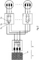
- the drive has an electric motor 4 which is fed from a converter 3, which is supplied from a network 1, in particular a three-phase supply network, or feeds back into this network.
- the converter 3 is designed as a cycloconverter, which has an inverter on the motor side and also an inverter on the network side, in particular the latter being designed as a rectifier capable of feedback.
- the output-side connections of the motor-side inverter are electrically connected to the connections of the motor 4, in particular to the connections of the stator winding of the motor 4, the input-side connections of the motor-side inverter are directly connected to a grid-side inverter, in particular to its DC voltage connection.
- the electrical power generated by the motor 4 during generator operation can be dissipated from the motor-side inverter to the network-side inverter, which is also connected.
- This grid-side inverter is connected to the grid 1 via a filter 2 with its connections facing away from the motor-side inverter.
- the line-side inverter works as a rectifier.
- a diode in particular as a freewheeling diode, is connected in parallel to each of its circuit breakers. These diodes then form a three-phase bridge rectifier.
- the electrical power is supplied directly to the motor-side inverter, which supplies the motor with a three-phase voltage whose frequency is one of the Inverter driving signal electronics is determined.
- the signal electronics control the semiconductor switches of the inverters, which are interconnected in half-bridges, with pulse-width modulated control signals.
- the filter 2 arranged between the grid-side inverter and the grid 1 has three filter inductances L F , each of the three grid phases being routed through one of the filter inductances L F .
- Each of the three filter inductances L F is the same size, especially if no production-related tolerances are taken into account.
- a first filter capacitance CF and a first additional capacitance Cs are arranged between a first of the mains phases and a second of the mains phases, so that these two capacitances would be connected in parallel, neglecting the line inductances.
- a second filter capacitance CF and a second additional capacitance Cs are arranged between a second of the mains phases and a third of the mains phases, so that these two capacitances would be connected in parallel, neglecting the line inductances.
- a third filter capacitance CF and a third additional capacitance Cs are arranged between the first of the mains phases and the third of the mains phases, so that these two capacitances would be connected in parallel, neglecting the line inductances.
- the first, second and third filter capacitors C F are each dimensioned to be the same, particularly if no production-related tolerances are taken into account.
- the first, second and third additional capacitances Cs are each dimensioned to be the same, particularly if no production-related tolerances are taken into account.
- the sum of the two capacitance values C F and C S is dimensioned such that the low-pass filter formed from this capacitance and the line inductance L N and the filter inductance L F pulse-frequency power components of the converter, in particular the motor-side Inverter, as well as voltage dips due to the commutation of the grid-side inverter are sufficiently damped and thus kept away from the grid 1 and other consumers connected to the grid 1 substantially.
- additional capacitances Cs are arranged in such a way that they are as close as possible to the converter. They are therefore connected with as little inductance as possible.
- the distance from the additional capacitances Cs to the converter, in particular to the semiconductor switches of the line-side inverter of the converter, is smaller than the distance to the filter capacitances C F and/or to the filter inductances L F .
- the line inductance between the additional capacitances Cs and the semiconductor switches of the line-side inverter is smaller, in particular at least ten times smaller, than the line inductance between the additional capacitances C S and the filter capacitances C F .
- the respective amount of a respective additional capacitance Cs is between three and nine times smaller than the respective amount of a respective filter capacitance C F .
- the arrangement of the three additional capacitances Cs on the three mains phases is referred to below as the additional capacitance arrangement.
- filter 2 The arrangement of the three filter inductances L N in the three mains phases together with the filter capacitances C F arranged between the mains phases is referred to as filter 2 below.
- the overall filter formed from filter 2 and the additional capacitance arrangement is therefore a passive filter.
- An additional capacitance arrangement is connected upstream of each converter.
- the additional capacitance arrangement is preferably structurally connected, in particular arranged and/or integrated in the housing of the respective converter.
- the converters are thus fed in parallel from the filter 2 via these additional capacitance arrangements.
- only a single filter 2 is required for multiple converters.
- One of the motors can also be used as a flywheel drive.
- One of the drives in particular the motor of this drive, is designed with a flywheel. Since the converters are connected in parallel via the additional capacity arrangements, energy can also be exchanged between the drive, which is designed as a flywheel mass storage device, and the other drives, in particular converters. So if the motors of the other drives are operated as motors, energy is taken from the flywheel mass storage and fed to the other converters. However, if the motors of the other drives produce more power as a generator than they consume as a motor, this excess electrical power can be supplied to the flywheel mass accumulator as long as it is not yet fully charged, i.e. has not yet reached its loading capacity limit.
- Fuses 6 can be provided on the output side of the filter 2 facing away from the network 1 . At least one fuse 6 can be assigned to each of the output phases. In addition, switches can be provided.
- At least one fuse 6 is arranged in each line phase.
- switches can be provided.
- the converter can be designed as a structural unit with the motor 4, i.e. the converter inside the housing of the motor 4 arrangeable.
- the housing of the motor 4 also includes the connection box of the motor, so that the converter 3 can also be arranged inside the connection box.
- the filter 2 is then connected via electrical lines to the converter 3 arranged in the housing of the motor.
- a star circuit could also be implemented in further exemplary embodiments according to the invention, in which case the effort required to produce the associated connections can be greater here because a respective star point has to be provided.
Landscapes
- Engineering & Computer Science (AREA)
- Power Engineering (AREA)
- Inverter Devices (AREA)
Claims (13)
- Installation comprenant un réseau (1), à savoir, en particulier un réseau d'alimentation électrique, un filtre (2) notamment unique, et plusieurs entraînements,le filtre (2) étant raccordé d'une part au réseau (1), notamment côté entrée, et d'autre part aux entraînements, notamment côté sortie, à l'aide d'au moins un conducteur électrique, chaque entraînement étant muni d'un ensemble de condensateurs additionnels, raccordé audit conducteur électrique et implanté au niveau de la connexion de tension alternative d'un onduleur dont la connexion de tension continue est raccordée à la connexion de tension continue d'un onduleur situé côté moteur, dont la sortie de tension alternative alimente un moteur électrique (4),de telle sorte que les deux onduleurs considérés, interposés entre l'ensemble respectif de condensateurs additionnels et le moteur respectif, remplissent la fonction d'un cycloconvertisseur (3) respectif,sachant que les ensembles respectifs de condensateurs additionnels sont branchés en parallèle côté filtre.
- Installation selon la revendication 1,
caractérisée par le fait que
le filtre (2) comporte, à chaque fois, une inductance de filtrage LF dans chacune des phases du réseau,
un condensateur de filtrage CF étant interposé, à chaque fois, entre deux phases respectives au sein desdites phases du réseau. - Installation selon la revendication 1,
caractérisée par le fait que
le filtre (2) comporte, à chaque fois, une inductance de filtrage LF dans chacune des phases du réseau,
un condensateur de filtrage CF étant interposé, à chaque fois, entre un point neutre et chacune desdites phases du réseau. - Installation selon au moins l'une des revendications précédentes, caractérisée par le fait que
tous les ensembles de condensateurs additionnels considérés sont alimentés en commun à partir du filtre (2). - Installation selon au moins l'une des revendications précédentes, caractérisée par le fait que- l'ensemble de condensateurs additionnels est pourvu, à chaque fois, d'un condensateur additionnel Cs entre deux phases respectives au sein des phases du réseau ;ou par le fait que- ledit ensemble de condensateurs additionnels est pourvu, à chaque fois, d'un condensateur additionnel Cs entre un point neutre et chacune desdites phases du réseau.
- Installation selon la revendication 5,
caractérisée par le fait que
le condensateur additionnel Cs est entre trois fois et neuf fois plus petit que le condensateur de filtrage CF. - Installation selon au moins l'une des revendications précédentes, caractérisée par le fait que,
dans chaque phase du réseau, l'inductance de ligne entre l'ensemble de condensateurs additionnels et un commutateur respectif à semi-conducteur, raccordé électriquement, de l'onduleur situé côté réseau, est inférieure à l'inductance de ligne entre ledit ensemble de condensateurs additionnels et le filtre (2). - Installation selon au moins l'une des revendications précédentes, caractérisée par le fait
qu'au moins l'un des entraînements entraîne un volant d'inertie (5), de sorte que cet entraînement est notamment réalisé en tant qu'accumulateur à volant d'inertie. - Installation selon l'une des revendications 5 à 8,
caractérisée par le fait que
l'éloignement des condensateurs additionnels Cs vis-à-vis du convertisseur, notamment vis-à-vis des commutateurs à semi-conducteurs de l'onduleur dudit convertisseur, situé côté réseau, est moindre que l'éloignement vis-à-vis des condensateurs de filtrage CF et/ou vis-à-vis des inductances de filtrage LF. - Installation selon au moins l'une des revendications précédentes, caractérisée par le fait que
des fusibles sont prévus du côté sortie du filtre (2) tourné à l'opposé du réseau (1),
au moins un fusible (6) étant respectivement associé à chacune des phases du côté sortie, sachant notamment qu'au moins un fusible (6) est respectivement implanté dans chacune desdites phases du côté sortie. - Installation selon au moins l'une des revendications précédentes, caractérisée par le fait
qu'un moins un fusible (6) est respectivement implanté dans chaque phase du réseau côté entrée, c'est-à-dire du côté, tourné vers le filtre (2), d'un ensemble de condensateurs additionnels considéré d'un convertisseur respectif. - Installation selon au moins l'une des revendications précédentes,caractérisée par le fait quechaque entraînement est réalisé sous la forme d'un entraînement direct, sachant, par conséquent, que chaque entraînement comprend un onduleur situé côté réseau, notamment un onduleur raccordé à l'ensemble de condensateurs additionnels, un moteur électrique (4) et un onduleur situé côté moteur,la connexion de tension continue dudit onduleur situé côté réseau étant raccordée à la connexion de tension continue dudit onduleur situé côté moteur,lequel moteur est raccordé à la connexion de tension alternative dudit onduleur situé côté moteur,ledit ensemble de condensateurs additionnels étant raccordé à la connexion de tension alternative dudit onduleur situé côté réseau.
- Installation selon l'une des revendications 2 à 12,
caractérisée par le fait que
la somme des deux valeurs capacitives du condensateur de filtrage CF et du condensateur additionnel Cs est calculée de façon telle qu'un filtre passe-bas constitué sur la base de cette somme, ainsi que d'une inductance de réseau LN et d'une inductance de filtrage LF, amortisse suffisamment des composants de puissance à fréquence d'impulsions du convertisseur, en particulier de l'onduleur situé côté moteur, et les maintienne ainsi à distance dudit réseau (1).
Applications Claiming Priority (2)
| Application Number | Priority Date | Filing Date | Title |
|---|---|---|---|
| DE102015013671.2A DE102015013671A1 (de) | 2015-10-23 | 2015-10-23 | Anlage, aufweisend ein Netz einen Filter und einen oder mehrere Antriebe |
| PCT/EP2016/025109 WO2017067669A1 (fr) | 2015-10-23 | 2016-10-11 | Installation, comportant un réseau, un filtre et un ou plusieurs dispositifs d'entraînement |
Publications (2)
| Publication Number | Publication Date |
|---|---|
| EP3365963A1 EP3365963A1 (fr) | 2018-08-29 |
| EP3365963B1 true EP3365963B1 (fr) | 2022-08-24 |
Family
ID=57133125
Family Applications (1)
| Application Number | Title | Priority Date | Filing Date |
|---|---|---|---|
| EP16781292.4A Active EP3365963B1 (fr) | 2015-10-23 | 2016-10-11 | Installation, comportant un réseau, un filtre et plusieurs dispositifs d'entraînement |
Country Status (3)
| Country | Link |
|---|---|
| EP (1) | EP3365963B1 (fr) |
| DE (1) | DE102015013671A1 (fr) |
| WO (1) | WO2017067669A1 (fr) |
Family Cites Families (4)
| Publication number | Priority date | Publication date | Assignee | Title |
|---|---|---|---|---|
| TWI282204B (en) * | 2003-08-12 | 2007-06-01 | Hitachi Ltd | Power conversion device using matrix converter |
| WO2006035752A1 (fr) * | 2004-09-29 | 2006-04-06 | Kabushiki Kaisha Yaskawa Denki | Convertisseur de matrices multiplex paralleles |
| EP2973964A4 (fr) * | 2013-03-13 | 2016-12-14 | Kone Corp | Agencement, convertisseur de fréquence et système élévateur |
| US9294005B2 (en) * | 2013-10-01 | 2016-03-22 | Rockwell Automation Technologies, Inc. | Method and apparatus for detecting AFE filter capacitor degradation |
-
2015
- 2015-10-23 DE DE102015013671.2A patent/DE102015013671A1/de active Pending
-
2016
- 2016-10-11 EP EP16781292.4A patent/EP3365963B1/fr active Active
- 2016-10-11 WO PCT/EP2016/025109 patent/WO2017067669A1/fr not_active Ceased
Also Published As
| Publication number | Publication date |
|---|---|
| DE102015013671A1 (de) | 2017-04-27 |
| EP3365963A1 (fr) | 2018-08-29 |
| WO2017067669A1 (fr) | 2017-04-27 |
Similar Documents
| Publication | Publication Date | Title |
|---|---|---|
| EP2432109B1 (fr) | Commutateur modulaire pour un convertisseur électrique, convertisseur électrique et procédé de fonctionnement d'un convertisseur électrique | |
| EP2411240B1 (fr) | Systeme d'entrainement electrique, son procédé de fonctionnement | |
| EP2608344A1 (fr) | Procédé de protection d'un condensateur de circuit intermédiaire dans un circuit de convertisseur | |
| EP2845288B1 (fr) | Couplage ou découplage de puissance dans une dérivation à un noeud de un réseau dc par une source de tension connectée en série | |
| EP3338353B1 (fr) | Convertisseur de tension, système d'entraînement électrique et procédé de réduction des tensions parasites | |
| EP3002866A1 (fr) | Convertisseur de circuit de tension intermédiaire dans une topologie à cinq points | |
| EP2541746B1 (fr) | Procédé de déchartge d'un condensateur de circuit intermédiaire d'un convertisseur et circuit correspondant | |
| EP2067227B1 (fr) | Alimentation en énergie motrice pour véhicules ferroviaires | |
| WO2014206704A1 (fr) | Ensemble mutateur à mutateurs multi-étages câblés en parallèle et son procédé de commande | |
| EP2979352A2 (fr) | Dispositif, en particulier machine ou installation, et procédé permettant de faire fonctionner un dispositif | |
| EP2592745A1 (fr) | Convertisseur électrique | |
| DE102015013875A1 (de) | Wechseleinrichter für eine elektrische Maschine, elektrische Antriebseinrichtung für ein Kraftfahrzeug sowie Verfahren zum Betreiben eines Wechselrichters | |
| WO2002015376A1 (fr) | Dispositif d'antiparasitage par mise a la masse d'un convertisseur matriciel | |
| EP3338351B1 (fr) | Circuit onduleur pourvu d'un dispositif de commutation pour l'atténuation régénérative d'oscillations électriques et procédé pour l'atténuation régénérative d'oscillations électriques | |
| EP3365963B1 (fr) | Installation, comportant un réseau, un filtre et plusieurs dispositifs d'entraînement | |
| DE102012206801A1 (de) | Schaltung mit einer stromrichterschaltung und verfahren zur leistungsanpassung | |
| EP2477301A1 (fr) | Dispositif d'alimentation en énergie électrique d'un réseau d'alimentation en énergie | |
| DE102005019215A1 (de) | Ausgangsfilter für einen gepulsten Stromrichter | |
| EP3513475B1 (fr) | Système servant à transmettre une puissance électrique comprenant une unité de filtrage | |
| DE102020106349A1 (de) | Elektrische Schaltungsanordnung und Kraftfahrzeug | |
| DE102015105889A1 (de) | Schaltmodul und Umrichter mit wenigstens einem Schaltmodul | |
| EP2713494A1 (fr) | Dispositif d'alimentation en énergie pour l'alimentation de l'énergie électrique générée par l'énergie cinétique dans un réseau de distribution de courant triphasé | |
| EP1619781B1 (fr) | Circuit pour un convertisseur | |
| EP2642652A1 (fr) | Convertisseur de source de tension avec circuit intermédiaire de capacité faible (F3E) et avec condensateur additif controlé et procédé de fonctionnement | |
| DE102013207894A1 (de) | Elektrische Schaltung |
Legal Events
| Date | Code | Title | Description |
|---|---|---|---|
| STAA | Information on the status of an ep patent application or granted ep patent |
Free format text: STATUS: THE INTERNATIONAL PUBLICATION HAS BEEN MADE |
|
| PUAI | Public reference made under article 153(3) epc to a published international application that has entered the european phase |
Free format text: ORIGINAL CODE: 0009012 |
|
| STAA | Information on the status of an ep patent application or granted ep patent |
Free format text: STATUS: REQUEST FOR EXAMINATION WAS MADE |
|
| 17P | Request for examination filed |
Effective date: 20180523 |
|
| AK | Designated contracting states |
Kind code of ref document: A1 Designated state(s): AL AT BE BG CH CY CZ DE DK EE ES FI FR GB GR HR HU IE IS IT LI LT LU LV MC MK MT NL NO PL PT RO RS SE SI SK SM TR |
|
| AX | Request for extension of the european patent |
Extension state: BA ME |
|
| RIN1 | Information on inventor provided before grant (corrected) |
Inventor name: SCHMIDT, JOSEF Inventor name: ZOELLER, THOMAS Inventor name: HAUCK, MATTHIAS Inventor name: BACKES, MANFRED |
|
| DAV | Request for validation of the european patent (deleted) | ||
| DAX | Request for extension of the european patent (deleted) | ||
| STAA | Information on the status of an ep patent application or granted ep patent |
Free format text: STATUS: EXAMINATION IS IN PROGRESS |
|
| 17Q | First examination report despatched |
Effective date: 20210503 |
|
| GRAP | Despatch of communication of intention to grant a patent |
Free format text: ORIGINAL CODE: EPIDOSNIGR1 |
|
| STAA | Information on the status of an ep patent application or granted ep patent |
Free format text: STATUS: GRANT OF PATENT IS INTENDED |
|
| INTG | Intention to grant announced |
Effective date: 20220411 |
|
| GRAS | Grant fee paid |
Free format text: ORIGINAL CODE: EPIDOSNIGR3 |
|
| GRAA | (expected) grant |
Free format text: ORIGINAL CODE: 0009210 |
|
| STAA | Information on the status of an ep patent application or granted ep patent |
Free format text: STATUS: THE PATENT HAS BEEN GRANTED |
|
| AK | Designated contracting states |
Kind code of ref document: B1 Designated state(s): AL AT BE BG CH CY CZ DE DK EE ES FI FR GB GR HR HU IE IS IT LI LT LU LV MC MK MT NL NO PL PT RO RS SE SI SK SM TR |
|
| REG | Reference to a national code |
Ref country code: CH Ref legal event code: EP |
|
| REG | Reference to a national code |
Ref country code: IE Ref legal event code: FG4D Free format text: LANGUAGE OF EP DOCUMENT: GERMAN |
|
| REG | Reference to a national code |
Ref country code: AT Ref legal event code: REF Ref document number: 1514356 Country of ref document: AT Kind code of ref document: T Effective date: 20220915 Ref country code: DE Ref legal event code: R096 Ref document number: 502016015212 Country of ref document: DE |
|
| REG | Reference to a national code |
Ref country code: LT Ref legal event code: MG9D |
|
| REG | Reference to a national code |
Ref country code: NL Ref legal event code: MP Effective date: 20220824 |
|
| PG25 | Lapsed in a contracting state [announced via postgrant information from national office to epo] |
Ref country code: SE Free format text: LAPSE BECAUSE OF FAILURE TO SUBMIT A TRANSLATION OF THE DESCRIPTION OR TO PAY THE FEE WITHIN THE PRESCRIBED TIME-LIMIT Effective date: 20220824 Ref country code: RS Free format text: LAPSE BECAUSE OF FAILURE TO SUBMIT A TRANSLATION OF THE DESCRIPTION OR TO PAY THE FEE WITHIN THE PRESCRIBED TIME-LIMIT Effective date: 20220824 Ref country code: PT Free format text: LAPSE BECAUSE OF FAILURE TO SUBMIT A TRANSLATION OF THE DESCRIPTION OR TO PAY THE FEE WITHIN THE PRESCRIBED TIME-LIMIT Effective date: 20221226 Ref country code: NO Free format text: LAPSE BECAUSE OF FAILURE TO SUBMIT A TRANSLATION OF THE DESCRIPTION OR TO PAY THE FEE WITHIN THE PRESCRIBED TIME-LIMIT Effective date: 20221124 Ref country code: NL Free format text: LAPSE BECAUSE OF FAILURE TO SUBMIT A TRANSLATION OF THE DESCRIPTION OR TO PAY THE FEE WITHIN THE PRESCRIBED TIME-LIMIT Effective date: 20220824 Ref country code: LV Free format text: LAPSE BECAUSE OF FAILURE TO SUBMIT A TRANSLATION OF THE DESCRIPTION OR TO PAY THE FEE WITHIN THE PRESCRIBED TIME-LIMIT Effective date: 20220824 Ref country code: LT Free format text: LAPSE BECAUSE OF FAILURE TO SUBMIT A TRANSLATION OF THE DESCRIPTION OR TO PAY THE FEE WITHIN THE PRESCRIBED TIME-LIMIT Effective date: 20220824 Ref country code: FI Free format text: LAPSE BECAUSE OF FAILURE TO SUBMIT A TRANSLATION OF THE DESCRIPTION OR TO PAY THE FEE WITHIN THE PRESCRIBED TIME-LIMIT Effective date: 20220824 |
|
| PG25 | Lapsed in a contracting state [announced via postgrant information from national office to epo] |
Ref country code: PL Free format text: LAPSE BECAUSE OF FAILURE TO SUBMIT A TRANSLATION OF THE DESCRIPTION OR TO PAY THE FEE WITHIN THE PRESCRIBED TIME-LIMIT Effective date: 20220824 Ref country code: IS Free format text: LAPSE BECAUSE OF FAILURE TO SUBMIT A TRANSLATION OF THE DESCRIPTION OR TO PAY THE FEE WITHIN THE PRESCRIBED TIME-LIMIT Effective date: 20221224 Ref country code: HR Free format text: LAPSE BECAUSE OF FAILURE TO SUBMIT A TRANSLATION OF THE DESCRIPTION OR TO PAY THE FEE WITHIN THE PRESCRIBED TIME-LIMIT Effective date: 20220824 Ref country code: GR Free format text: LAPSE BECAUSE OF FAILURE TO SUBMIT A TRANSLATION OF THE DESCRIPTION OR TO PAY THE FEE WITHIN THE PRESCRIBED TIME-LIMIT Effective date: 20221125 |
|
| PG25 | Lapsed in a contracting state [announced via postgrant information from national office to epo] |
Ref country code: SM Free format text: LAPSE BECAUSE OF FAILURE TO SUBMIT A TRANSLATION OF THE DESCRIPTION OR TO PAY THE FEE WITHIN THE PRESCRIBED TIME-LIMIT Effective date: 20220824 Ref country code: RO Free format text: LAPSE BECAUSE OF FAILURE TO SUBMIT A TRANSLATION OF THE DESCRIPTION OR TO PAY THE FEE WITHIN THE PRESCRIBED TIME-LIMIT Effective date: 20220824 Ref country code: ES Free format text: LAPSE BECAUSE OF FAILURE TO SUBMIT A TRANSLATION OF THE DESCRIPTION OR TO PAY THE FEE WITHIN THE PRESCRIBED TIME-LIMIT Effective date: 20220824 Ref country code: DK Free format text: LAPSE BECAUSE OF FAILURE TO SUBMIT A TRANSLATION OF THE DESCRIPTION OR TO PAY THE FEE WITHIN THE PRESCRIBED TIME-LIMIT Effective date: 20220824 Ref country code: CZ Free format text: LAPSE BECAUSE OF FAILURE TO SUBMIT A TRANSLATION OF THE DESCRIPTION OR TO PAY THE FEE WITHIN THE PRESCRIBED TIME-LIMIT Effective date: 20220824 |
|
| REG | Reference to a national code |
Ref country code: DE Ref legal event code: R097 Ref document number: 502016015212 Country of ref document: DE |
|
| PG25 | Lapsed in a contracting state [announced via postgrant information from national office to epo] |
Ref country code: SK Free format text: LAPSE BECAUSE OF FAILURE TO SUBMIT A TRANSLATION OF THE DESCRIPTION OR TO PAY THE FEE WITHIN THE PRESCRIBED TIME-LIMIT Effective date: 20220824 Ref country code: MC Free format text: LAPSE BECAUSE OF FAILURE TO SUBMIT A TRANSLATION OF THE DESCRIPTION OR TO PAY THE FEE WITHIN THE PRESCRIBED TIME-LIMIT Effective date: 20220824 Ref country code: EE Free format text: LAPSE BECAUSE OF FAILURE TO SUBMIT A TRANSLATION OF THE DESCRIPTION OR TO PAY THE FEE WITHIN THE PRESCRIBED TIME-LIMIT Effective date: 20220824 |
|
| REG | Reference to a national code |
Ref country code: CH Ref legal event code: PL |
|
| REG | Reference to a national code |
Ref country code: BE Ref legal event code: MM Effective date: 20221031 |
|
| PG25 | Lapsed in a contracting state [announced via postgrant information from national office to epo] |
Ref country code: LU Free format text: LAPSE BECAUSE OF NON-PAYMENT OF DUE FEES Effective date: 20221011 Ref country code: AL Free format text: LAPSE BECAUSE OF FAILURE TO SUBMIT A TRANSLATION OF THE DESCRIPTION OR TO PAY THE FEE WITHIN THE PRESCRIBED TIME-LIMIT Effective date: 20220824 |
|
| PLBE | No opposition filed within time limit |
Free format text: ORIGINAL CODE: 0009261 |
|
| STAA | Information on the status of an ep patent application or granted ep patent |
Free format text: STATUS: NO OPPOSITION FILED WITHIN TIME LIMIT |
|
| GBPC | Gb: european patent ceased through non-payment of renewal fee |
Effective date: 20221124 |
|
| PG25 | Lapsed in a contracting state [announced via postgrant information from national office to epo] |
Ref country code: LI Free format text: LAPSE BECAUSE OF NON-PAYMENT OF DUE FEES Effective date: 20221031 Ref country code: FR Free format text: LAPSE BECAUSE OF NON-PAYMENT OF DUE FEES Effective date: 20221024 Ref country code: CH Free format text: LAPSE BECAUSE OF NON-PAYMENT OF DUE FEES Effective date: 20221031 |
|
| 26N | No opposition filed |
Effective date: 20230525 |
|
| PG25 | Lapsed in a contracting state [announced via postgrant information from national office to epo] |
Ref country code: SI Free format text: LAPSE BECAUSE OF FAILURE TO SUBMIT A TRANSLATION OF THE DESCRIPTION OR TO PAY THE FEE WITHIN THE PRESCRIBED TIME-LIMIT Effective date: 20220824 |
|
| PG25 | Lapsed in a contracting state [announced via postgrant information from national office to epo] |
Ref country code: BE Free format text: LAPSE BECAUSE OF NON-PAYMENT OF DUE FEES Effective date: 20221031 |
|
| PG25 | Lapsed in a contracting state [announced via postgrant information from national office to epo] |
Ref country code: IE Free format text: LAPSE BECAUSE OF NON-PAYMENT OF DUE FEES Effective date: 20221011 Ref country code: GB Free format text: LAPSE BECAUSE OF NON-PAYMENT OF DUE FEES Effective date: 20221124 |
|
| REG | Reference to a national code |
Ref country code: AT Ref legal event code: MM01 Ref document number: 1514356 Country of ref document: AT Kind code of ref document: T Effective date: 20221011 |
|
| PG25 | Lapsed in a contracting state [announced via postgrant information from national office to epo] |
Ref country code: AT Free format text: LAPSE BECAUSE OF NON-PAYMENT OF DUE FEES Effective date: 20221011 |
|
| PG25 | Lapsed in a contracting state [announced via postgrant information from national office to epo] |
Ref country code: HU Free format text: LAPSE BECAUSE OF FAILURE TO SUBMIT A TRANSLATION OF THE DESCRIPTION OR TO PAY THE FEE WITHIN THE PRESCRIBED TIME-LIMIT; INVALID AB INITIO Effective date: 20161011 |
|
| PG25 | Lapsed in a contracting state [announced via postgrant information from national office to epo] |
Ref country code: CY Free format text: LAPSE BECAUSE OF FAILURE TO SUBMIT A TRANSLATION OF THE DESCRIPTION OR TO PAY THE FEE WITHIN THE PRESCRIBED TIME-LIMIT Effective date: 20220824 |
|
| PG25 | Lapsed in a contracting state [announced via postgrant information from national office to epo] |
Ref country code: MK Free format text: LAPSE BECAUSE OF FAILURE TO SUBMIT A TRANSLATION OF THE DESCRIPTION OR TO PAY THE FEE WITHIN THE PRESCRIBED TIME-LIMIT Effective date: 20220824 Ref country code: IT Free format text: LAPSE BECAUSE OF FAILURE TO SUBMIT A TRANSLATION OF THE DESCRIPTION OR TO PAY THE FEE WITHIN THE PRESCRIBED TIME-LIMIT Effective date: 20220824 |
|
| PG25 | Lapsed in a contracting state [announced via postgrant information from national office to epo] |
Ref country code: BG Free format text: LAPSE BECAUSE OF FAILURE TO SUBMIT A TRANSLATION OF THE DESCRIPTION OR TO PAY THE FEE WITHIN THE PRESCRIBED TIME-LIMIT Effective date: 20220824 |
|
| PG25 | Lapsed in a contracting state [announced via postgrant information from national office to epo] |
Ref country code: MT Free format text: LAPSE BECAUSE OF FAILURE TO SUBMIT A TRANSLATION OF THE DESCRIPTION OR TO PAY THE FEE WITHIN THE PRESCRIBED TIME-LIMIT Effective date: 20220824 |
|
| PG25 | Lapsed in a contracting state [announced via postgrant information from national office to epo] |
Ref country code: TR Free format text: LAPSE BECAUSE OF FAILURE TO SUBMIT A TRANSLATION OF THE DESCRIPTION OR TO PAY THE FEE WITHIN THE PRESCRIBED TIME-LIMIT Effective date: 20220824 |
|
| PGFP | Annual fee paid to national office [announced via postgrant information from national office to epo] |
Ref country code: DE Payment date: 20251031 Year of fee payment: 10 |