EP3365973B1 - Élément arrière pour module solaire - Google Patents
Élément arrière pour module solaire Download PDFInfo
- Publication number
- EP3365973B1 EP3365973B1 EP16784174.1A EP16784174A EP3365973B1 EP 3365973 B1 EP3365973 B1 EP 3365973B1 EP 16784174 A EP16784174 A EP 16784174A EP 3365973 B1 EP3365973 B1 EP 3365973B1
- Authority
- EP
- European Patent Office
- Prior art keywords
- material sheet
- rear face
- plane
- face element
- solar
- Prior art date
- Legal status (The legal status is an assumption and is not a legal conclusion. Google has not performed a legal analysis and makes no representation as to the accuracy of the status listed.)
- Active
Links
Images

Classifications
-
- H—ELECTRICITY
- H10—SEMICONDUCTOR DEVICES; ELECTRIC SOLID-STATE DEVICES NOT OTHERWISE PROVIDED FOR
- H10F—INORGANIC SEMICONDUCTOR DEVICES SENSITIVE TO INFRARED RADIATION, LIGHT, ELECTROMAGNETIC RADIATION OF SHORTER WAVELENGTH OR CORPUSCULAR RADIATION
- H10F19/00—Integrated devices, or assemblies of multiple devices, comprising at least one photovoltaic cell covered by group H10F10/00, e.g. photovoltaic modules
- H10F19/20—Integrated devices, or assemblies of multiple devices, comprising at least one photovoltaic cell covered by group H10F10/00, e.g. photovoltaic modules comprising photovoltaic cells in arrays in or on a single semiconductor substrate, the photovoltaic cells having planar junctions
-
- H—ELECTRICITY
- H02—GENERATION; CONVERSION OR DISTRIBUTION OF ELECTRIC POWER
- H02S—GENERATION OF ELECTRIC POWER BY CONVERSION OF INFRARED RADIATION, VISIBLE LIGHT OR ULTRAVIOLET LIGHT, e.g. USING PHOTOVOLTAIC [PV] MODULES
- H02S20/00—Supporting structures for PV modules
-
- H—ELECTRICITY
- H02—GENERATION; CONVERSION OR DISTRIBUTION OF ELECTRIC POWER
- H02S—GENERATION OF ELECTRIC POWER BY CONVERSION OF INFRARED RADIATION, VISIBLE LIGHT OR ULTRAVIOLET LIGHT, e.g. USING PHOTOVOLTAIC [PV] MODULES
- H02S30/00—Structural details of PV modules other than those related to light conversion
- H02S30/10—Frame structures
-
- H—ELECTRICITY
- H02—GENERATION; CONVERSION OR DISTRIBUTION OF ELECTRIC POWER
- H02S—GENERATION OF ELECTRIC POWER BY CONVERSION OF INFRARED RADIATION, VISIBLE LIGHT OR ULTRAVIOLET LIGHT, e.g. USING PHOTOVOLTAIC [PV] MODULES
- H02S40/00—Components or accessories in combination with PV modules, not provided for in groups H02S10/00 - H02S30/00
- H02S40/40—Thermal components
- H02S40/42—Cooling means
-
- H—ELECTRICITY
- H10—SEMICONDUCTOR DEVICES; ELECTRIC SOLID-STATE DEVICES NOT OTHERWISE PROVIDED FOR
- H10F—INORGANIC SEMICONDUCTOR DEVICES SENSITIVE TO INFRARED RADIATION, LIGHT, ELECTROMAGNETIC RADIATION OF SHORTER WAVELENGTH OR CORPUSCULAR RADIATION
- H10F19/00—Integrated devices, or assemblies of multiple devices, comprising at least one photovoltaic cell covered by group H10F10/00, e.g. photovoltaic modules
- H10F19/80—Encapsulations or containers for integrated devices, or assemblies of multiple devices, having photovoltaic cells
- H10F19/85—Protective back sheets
-
- F—MECHANICAL ENGINEERING; LIGHTING; HEATING; WEAPONS; BLASTING
- F21—LIGHTING
- F21S—NON-PORTABLE LIGHTING DEVICES; SYSTEMS THEREOF; VEHICLE LIGHTING DEVICES SPECIALLY ADAPTED FOR VEHICLE EXTERIORS
- F21S9/00—Lighting devices with a built-in power supply; Systems employing lighting devices with a built-in power supply
- F21S9/02—Lighting devices with a built-in power supply; Systems employing lighting devices with a built-in power supply the power supply being a battery or accumulator
- F21S9/03—Lighting devices with a built-in power supply; Systems employing lighting devices with a built-in power supply the power supply being a battery or accumulator rechargeable by exposure to light
- F21S9/035—Lighting devices with a built-in power supply; Systems employing lighting devices with a built-in power supply the power supply being a battery or accumulator rechargeable by exposure to light the solar unit being integrated within the support for the lighting unit, e.g. within or on a pole
-
- F—MECHANICAL ENGINEERING; LIGHTING; HEATING; WEAPONS; BLASTING
- F21—LIGHTING
- F21S—NON-PORTABLE LIGHTING DEVICES; SYSTEMS THEREOF; VEHICLE LIGHTING DEVICES SPECIALLY ADAPTED FOR VEHICLE EXTERIORS
- F21S9/00—Lighting devices with a built-in power supply; Systems employing lighting devices with a built-in power supply
- F21S9/02—Lighting devices with a built-in power supply; Systems employing lighting devices with a built-in power supply the power supply being a battery or accumulator
- F21S9/03—Lighting devices with a built-in power supply; Systems employing lighting devices with a built-in power supply the power supply being a battery or accumulator rechargeable by exposure to light
- F21S9/037—Lighting devices with a built-in power supply; Systems employing lighting devices with a built-in power supply the power supply being a battery or accumulator rechargeable by exposure to light the solar unit and the lighting unit being located within or on the same housing
-
- F—MECHANICAL ENGINEERING; LIGHTING; HEATING; WEAPONS; BLASTING
- F24—HEATING; RANGES; VENTILATING
- F24S—SOLAR HEAT COLLECTORS; SOLAR HEAT SYSTEMS
- F24S20/00—Solar heat collectors specially adapted for particular uses or environments
- F24S2020/10—Solar modules layout; Modular arrangements
- F24S2020/12—Coplanar arrangements with frame overlapping portions
-
- F—MECHANICAL ENGINEERING; LIGHTING; HEATING; WEAPONS; BLASTING
- F24—HEATING; RANGES; VENTILATING
- F24S—SOLAR HEAT COLLECTORS; SOLAR HEAT SYSTEMS
- F24S25/00—Arrangement of stationary mountings or supports for solar heat collector modules
- F24S25/10—Arrangement of stationary mountings or supports for solar heat collector modules extending in directions away from a supporting surface
- F24S25/12—Arrangement of stationary mountings or supports for solar heat collector modules extending in directions away from a supporting surface using posts in combination with upper profiles
-
- F—MECHANICAL ENGINEERING; LIGHTING; HEATING; WEAPONS; BLASTING
- F24—HEATING; RANGES; VENTILATING
- F24S—SOLAR HEAT COLLECTORS; SOLAR HEAT SYSTEMS
- F24S25/00—Arrangement of stationary mountings or supports for solar heat collector modules
- F24S25/20—Peripheral frames for modules
-
- F—MECHANICAL ENGINEERING; LIGHTING; HEATING; WEAPONS; BLASTING
- F24—HEATING; RANGES; VENTILATING
- F24S—SOLAR HEAT COLLECTORS; SOLAR HEAT SYSTEMS
- F24S25/00—Arrangement of stationary mountings or supports for solar heat collector modules
- F24S25/40—Arrangement of stationary mountings or supports for solar heat collector modules using plate-like mounting elements, e.g. profiled or corrugated plates; Plate-like module frames
-
- F—MECHANICAL ENGINEERING; LIGHTING; HEATING; WEAPONS; BLASTING
- F24—HEATING; RANGES; VENTILATING
- F24S—SOLAR HEAT COLLECTORS; SOLAR HEAT SYSTEMS
- F24S25/00—Arrangement of stationary mountings or supports for solar heat collector modules
- F24S25/60—Fixation means, e.g. fasteners, specially adapted for supporting solar heat collector modules
- F24S25/63—Fixation means, e.g. fasteners, specially adapted for supporting solar heat collector modules for fixing modules or their peripheral frames to supporting elements
-
- F—MECHANICAL ENGINEERING; LIGHTING; HEATING; WEAPONS; BLASTING
- F24—HEATING; RANGES; VENTILATING
- F24S—SOLAR HEAT COLLECTORS; SOLAR HEAT SYSTEMS
- F24S25/00—Arrangement of stationary mountings or supports for solar heat collector modules
- F24S25/60—Fixation means, e.g. fasteners, specially adapted for supporting solar heat collector modules
- F24S25/67—Fixation means, e.g. fasteners, specially adapted for supporting solar heat collector modules for coupling adjacent modules or their peripheral frames
-
- H—ELECTRICITY
- H02—GENERATION; CONVERSION OR DISTRIBUTION OF ELECTRIC POWER
- H02S—GENERATION OF ELECTRIC POWER BY CONVERSION OF INFRARED RADIATION, VISIBLE LIGHT OR ULTRAVIOLET LIGHT, e.g. USING PHOTOVOLTAIC [PV] MODULES
- H02S30/00—Structural details of PV modules other than those related to light conversion
-
- H—ELECTRICITY
- H10—SEMICONDUCTOR DEVICES; ELECTRIC SOLID-STATE DEVICES NOT OTHERWISE PROVIDED FOR
- H10N—ELECTRIC SOLID-STATE DEVICES NOT OTHERWISE PROVIDED FOR
- H10N30/00—Piezoelectric or electrostrictive devices
- H10N30/80—Constructional details
- H10N30/88—Mounts; Supports; Enclosures; Casings
-
- H—ELECTRICITY
- H10—SEMICONDUCTOR DEVICES; ELECTRIC SOLID-STATE DEVICES NOT OTHERWISE PROVIDED FOR
- H10W—GENERIC PACKAGES, INTERCONNECTIONS, CONNECTORS OR OTHER CONSTRUCTIONAL DETAILS OF DEVICES COVERED BY CLASS H10
- H10W40/00—Arrangements for thermal protection or thermal control
- H10W40/20—Arrangements for cooling
- H10W40/22—Arrangements for cooling characterised by their shape, e.g. having conical or cylindrical projections
-
- H—ELECTRICITY
- H10—SEMICONDUCTOR DEVICES; ELECTRIC SOLID-STATE DEVICES NOT OTHERWISE PROVIDED FOR
- H10W—GENERIC PACKAGES, INTERCONNECTIONS, CONNECTORS OR OTHER CONSTRUCTIONAL DETAILS OF DEVICES COVERED BY CLASS H10
- H10W40/00—Arrangements for thermal protection or thermal control
- H10W40/20—Arrangements for cooling
- H10W40/22—Arrangements for cooling characterised by their shape, e.g. having conical or cylindrical projections
- H10W40/226—Arrangements for cooling characterised by their shape, e.g. having conical or cylindrical projections characterised by projecting parts, e.g. fins to increase surface area
-
- H—ELECTRICITY
- H10—SEMICONDUCTOR DEVICES; ELECTRIC SOLID-STATE DEVICES NOT OTHERWISE PROVIDED FOR
- H10W—GENERIC PACKAGES, INTERCONNECTIONS, CONNECTORS OR OTHER CONSTRUCTIONAL DETAILS OF DEVICES COVERED BY CLASS H10
- H10W76/00—Containers; Fillings or auxiliary members therefor; Seals
- H10W76/10—Containers or parts thereof
-
- Y—GENERAL TAGGING OF NEW TECHNOLOGICAL DEVELOPMENTS; GENERAL TAGGING OF CROSS-SECTIONAL TECHNOLOGIES SPANNING OVER SEVERAL SECTIONS OF THE IPC; TECHNICAL SUBJECTS COVERED BY FORMER USPC CROSS-REFERENCE ART COLLECTIONS [XRACs] AND DIGESTS
- Y02—TECHNOLOGIES OR APPLICATIONS FOR MITIGATION OR ADAPTATION AGAINST CLIMATE CHANGE
- Y02E—REDUCTION OF GREENHOUSE GAS [GHG] EMISSIONS, RELATED TO ENERGY GENERATION, TRANSMISSION OR DISTRIBUTION
- Y02E10/00—Energy generation through renewable energy sources
- Y02E10/40—Solar thermal energy, e.g. solar towers
- Y02E10/44—Heat exchange systems
-
- Y—GENERAL TAGGING OF NEW TECHNOLOGICAL DEVELOPMENTS; GENERAL TAGGING OF CROSS-SECTIONAL TECHNOLOGIES SPANNING OVER SEVERAL SECTIONS OF THE IPC; TECHNICAL SUBJECTS COVERED BY FORMER USPC CROSS-REFERENCE ART COLLECTIONS [XRACs] AND DIGESTS
- Y02—TECHNOLOGIES OR APPLICATIONS FOR MITIGATION OR ADAPTATION AGAINST CLIMATE CHANGE
- Y02E—REDUCTION OF GREENHOUSE GAS [GHG] EMISSIONS, RELATED TO ENERGY GENERATION, TRANSMISSION OR DISTRIBUTION
- Y02E10/00—Energy generation through renewable energy sources
- Y02E10/50—Photovoltaic [PV] energy
Definitions
- the present invention relates to a back element for a solar module.
- the layer system which generally comprises a transparent substrate, in particular a glass substrate, and a back cover (backsheet) between which the solar cells are arranged, protects the solar cells from mechanical stress and weather influences.
- the electrical connectors between the solar cells are also enclosed in the layer system.
- Films made of EVA (ethylene vinyl acetate) or another suitable material are usually inserted between the layers mentioned so that the layer system can be laminated together under the influence of heat and pressure.
- a solar module includes electrical connections with which the solar cells enclosed by the layers can be contacted from the outside.
- the solar cells are usually connected in series to provide the desired output voltages, and several electrical connections are usually provided in order to be able to tap into separate circuits separately. Such separate tapping is necessary or advantageous, for example, if the solar modules are partially shaded. Therefore, there are usually a large number of electrical connections that must be contactable from the outside.
- Solar modules according to the state of the art require a relatively high frame and a thick glass substrate layer (approx. 3.2mm) in order to transfer the forces acting from the surface (snow, wind) first into the frame and then into the substructure at the clamping points.
- a frame height of 30mm to 40mm is currently common.
- Frame elements are pushed onto the module laminate on all four sides and permanently connected to the module laminate with tape or silicone. Adjacent frame parts are connected to each other at the frame corners using force, e.g. by pressing in an angle.
- the frame profile surrounds the module laminate, creating a step of approx. 1 mm in relation to the glass surface.
- Module assembly with clamps is therefore comparatively complex/expensive, not only in terms of the individual material required and the associated storage costs, but also in terms of the assembly time required.
- rod-shaped, box-shaped, U- or double-T-profile-shaped or otherwise designed backrails are attached to the back of the module laminate.
- the backrails also only rest on a few points on the back of the module. This means that the backrail has to be relatively high.
- the high backrails lead to a low packing density during shipping and thus to high transport costs, comparable to the well-known frame modules.
- backrails are usually used on one solar module. These are arranged in the middle of the back of the laminate, for example, and are attached in particular to the short protruding ends of the backrails, but they can also be attached at other points along the backrail. This has the particular disadvantage that there are large bending distances, which require the backrails to be larger.
- a particular disadvantage of the known solutions is that the rear side elements can even act as insulation and thus the solar cell temperature can be higher than with a conventional module with a standard frame.
- the present invention is therefore based on the object of overcoming the disadvantages of the prior art and in particular of providing a device for absorbing the forces acting on the solar modules and for fastening them, which enables efficient production and assembly, good cooling and reduced transport costs of solar modules.
- embossing and punching should not be understood to mean exclusively conventional mechanical metal processing, but rather all known separation processes, for example laser cutting or water jet cutting, grinding and the like.
- the linear course of the material web cuts should in particular not exclude the possibility that, according to one embodiment, the material web sections are twisted.
- parallel planes are not to be understood as exclusively two planes that are locally parallel everywhere, but the distance between the first plane and the second plane can also vary locally. However, it is preferred according to the invention that the surfaces are parallel on average over the module surface.
- the rear element according to the invention can be arranged on the rear of a solar module. Therefore, according to one embodiment of the present invention, it can be particularly advantageous that no peripheral frame edge is formed in accordance with the prior art and the associated disadvantages are avoided, in particular a critical point is eliminated where dirt can collect, which shades the solar cells and negatively affects the efficiency.
- the material web optionally forms a type of frame for the solar module at the edges by folding it over several times.
- the said frame according to the invention preferably has the height of the rear element, so that the disadvantages of the prior art can be avoided.
- the rear side element according to the invention has first and/or second material web sections running longitudinally and/or transversely to the solar module plane, which run in the first plane, which is further away from the solar module in the assembled state.
- the course of the material web sections can be linear, but all alternative courses are also conceivable, for example curved and/or jagged courses in order to form certain geometries such as a honeycomb pattern.
- the width of the material web sections and The distance between these and the solar module level can vary along the material web sections. This makes it possible for the stiffness of the material web sections to be locally adapted to the subsequent load.
- the load is absorbed over a large area when subjected to load (surface load such as wind, snow), unlike with framed modules. This means that the height of the module and the diameter of the glass substrate can be lower.
- the solar module can rest on the material web not only at four points (as with a framed module or modules with back rails), which act like longitudinal or transverse supports, but also along the longitudinal or transverse supports.
- the bending of the module resulting from surface loading only occurs orthogonally to the support, i.e. only in one direction and not in two directions at the same time as with a framed module.
- the mechanical stress on the cells is therefore much lower. This is especially true if the neutral phase is placed in the cell plane with a clever combination of the thickness of the glass substrate with the design of the back element (height, material, material thickness, geometry of the material webs).
- the cell breakage rates are similarly low as with a symmetrical glass/glass module, but at lower cost and with better cooling.
- the second level of the rear element according to the invention also acts as a heat conduction device and thus serves to cool the solar modules.
- the large surface of the entire material web is used to release the heat into the environment.
- Air can also flow through the rear element and contribute to further cooling.
- the large number of openings and struts between the two levels of the rear element creates a turbulent flow even at low flow speeds, which dissipates heat better.
- the cooling air can enter and exit from the area between the two levels in the areas between two material web sections, which produces a much better cooling effect than can be achieved with the rear side elements provided in the prior art.
- the air With the rear side elements according to the prior art, the air must flow through the entire length or width of the module, which, as already explained, on the one hand causes greater flow resistance and thus less air exchange and on the other hand reduces the temperature gradient between the module and the cooling air, which can even have an insulating effect. Since the conversion efficiency decreases with increasing solar cell temperature, the solution according to the invention is therefore particularly advantageous.
- a rear element according to the invention thus enables the use of just one component, which can be connected to a solar module easily, quickly and safely.
- the rear element can even be applied during the lamination process.
- the first level facing away from the solar module absorbs the tensile and compressive forces (when the module bends), the second level offers a large contact surface for heat dissipation.
- the thickness of the solar module can be reduced by better absorption of the forces that occur, both in terms of the layers of the module, especially the glass substrate, and in terms of the frame elements and backrails that are no longer required. This further reduces costs and optimizes transport options.
- the rear element according to the invention is thus able to absorb forces acting on solar modules and to fasten them, enables efficient production and assembly, good cooling and reduced transport costs of solar modules.
- first material web sections are arranged parallel to one another and/or the second material web sections are arranged parallel to one another.
- first material web sections extend continuously from a first side edge to an opposite second side edge of the material web in the first plane and/or the m second material web sections extend continuously from a third side edge of the material web to an opposite fourth side edge in the first plane.
- the material web sections themselves can be linear or curved or have any geometry.
- regions can be defined which are arranged in the second plane by means of forming. This can be advantageous according to an embodiment of the present invention.
- each of the planar elements of the second level is connected to the first and/or second material web sections of the first level by means of at least one, in particular four, spacing elements, wherein the spacing elements are formed by cutting and deforming the material web.
- cutting should be understood broadly and refers to the partial or complete severing of a section of material web or a material web.
- a large number of separation methods are known in the prior art for this purpose.
- the rear side element according to the invention is formed from a single material web, so that the spacing elements form the transition between the first and second levels.
- the spacing elements are in particular designed and configured to enable force transmission from the first to the second level.
- a first first material web section forms a first side end
- a second first material web section forms a second side end opposite the first side end
- a first second material web section forms a third side end arranged at right angles to the first and second side ends
- a second second material web section forms a fourth side end opposite the third side end
- the material web consists of and/or comprises metal, stainless steel, sheet steel, sheet iron, copper, brass, aluminum, plastic, injection-molded plastic and/or partially molded metal, and in particular has a thickness in a range from 0.2 mm to 4 mm, preferably in a range from 0.4 mm to 2 mm, particularly preferably in a range from 0.5 mm to 1 mm.
- the rear side element can also be advantageous for the rear side element to have at least one recess in the first plane and/or in the second plane in order to accommodate a connection box for electrically contacting a solar cell and/or a solar cell matrix and/or to enable electrically contacting a solar cell and/or a solar cell matrix, in particular the region of the cross-connectors of a solar cell and/or a solar cell matrix lying freely in the recess.
- a solar module includes electrical connections with which the solar cells enclosed by the layers can be contacted from the outside.
- the solar cells are usually connected in series to provide the desired output voltages, and in addition, several electrical connections are usually provided in order to be able to tap into separate circuits separately.
- Metal strips e.g. copper strips with or without additional metal or alloy coating, are used as cell connectors and cross connectors. For each connection between two solar cell strings to be electrically connected, such a metal strip is provided as a separate cross connector.
- the cell connectors themselves are then soldered to the cross connector. For example, before the solar module is laminated, connection lugs can be led out of the EVA backing film to create the electrical connections.
- connection elements such as sockets or plugs can then be connected to these externally led Connection lugs are connected, e.g. by soldering.
- a junction box is glued to the back of the laminate using silicone and then the connection lugs of the solar cells are electrically connected to the contacts of the junction box.
- the junction box itself can be filled with a material that hardens, in particular through radiation, to seal it and/or an optional sealing cover can be mounted over the junction box.
- the area between the connection box and the rear of the layer laminate is covered with the thermally conductive material of the material sheet and can thus serve to better dissipate the waste heat from the diodes that are in contact with the cross connectors.
- the material sheet comprises reinforcing elements, in particular arranged in the connection area of the rear element of the solar module with a substructure. This serves to stiffen the rear element and increases its stability.
- the second plane in particular at least one planar element of the second plane, is deformed in such a way that a third plane is formed and/or has a deformed, in particular embossed, surface structure, in particular is honeycomb-shaped.
- Such a third level and/or second level structure may, for example, serve to further optimize cooling and not to improve mechanical stiffness.
- edges of the material webs can be bent in the direction of the cell plane. This prevents cuts.
- retaining eyes, clamps, cable guides and/or cable channels are included for the electrical contacting of the solar cells and/or that the rear element has recesses in the edge area in order to enable safe transport of electrical contact elements, in particular cables and/or plugs, and to simplify/ensure their fastening after the solar module has been installed.
- This design makes it possible to dispense with additional mounting material (cable ties, etc.).
- At least one outer edge, in particular two opposite edges, preferably all edges, of the rear side element is or are formed by bending and in particular form a profile suitable for stiffening, in particular a box profile.
- Such bending serves to further stiffen the rear element.
- At least one outer edge, in particular two opposite edges, preferably all edges, of the rear side element comprise recesses and/or formations which can be brought into or are in operative connection with complementary recesses and/or formations of a further rear side element, wherein the recesses and/or formations are designed and configured to align two rear side elements with respect to one another.
- At least one outer edge, in particular two opposite edges, preferably all edges, of the rear element have fastening devices and/or recesses, in particular in the form of holes, designed and arranged to connect the rear element to another element and/or the substructure in a non-detachable or detachable manner.
- the rear element consists of a formed material web.
- the invention also provides a solar module comprising at least two solar cells and at least one rear side element according to the invention arranged on the rear side of the solar cells, wherein the second plane of the at least one rear side element is arranged facing the rear side of the solar cells.
- One or more backside elements can be positioned in strips of the same or different lengths on the backside of the layer composite in such a way that only the relevant areas to be supported are exposed to them, rather than the entire backsheet. It is possible, for example, to use specific designs of the backside element according to the invention for a tracker system or for a special insertion system. An optimal adaptation of the mechanical stability to the prevailing installation situation can thus be achieved with minimal use of material. However, it has proven to be advantageous if the main tension-compression direction of the layer system is completely covered by a rear element in order to be able to optimally absorb the forces that occur.
- the solar module does not comprise a module frame or a mounting system comprising backrails.
- the methods according to the invention enable a faster, simpler and more cost-effective manufacturing process for solar modules.
- an EVA layer is usually first placed on a glass substrate to form a substrate plate on which the solar cells are then placed.
- Another EVA layer and the backsheet, i.e. the rear laminate layer, are applied to the back of the solar cells and the module is then laminated. After lamination, the laminate is trimmed and the junction boxes for electrical contact are installed.
- the rear element according to the invention is already connected to the rear of the module during module construction, in particular glued flat in the contact areas. This is important for heat dissipation. The latter can take place during the lamination process (laminator, autoclave). This means that a number of work steps and machines can be saved compared to the classic module.
- the rear element can be bonded after the module has been laminated. In this case, too, A considerable number of work steps are saved because only one connection step is necessary.
- FIG. 1 a first embodiment of a rear side element 1 according to the invention is shown.
- the rear side element 1 consists of a formed material web 3, the material web 3 being arranged in sections in a first plane 5 and in sections in a second plane 7 parallel to the first plane 5.
- the material web 3 forms spacing elements 9 in order to space the first from the second plane 5, 7.
- Two first material web sections 11, 11 run parallel to one another and at right angles to two second material web sections 13, 13' arranged parallel to one another.
- the first material web section 11 has a first side end 15 and the second first material web section 11 has a second side end opposite the first side end 15 (not shown).
- the first second material web section 13 has a third side end 17 arranged at right angles to the first and second side ends 15 and the second second material web section 13' has a fourth side end 17' opposite the third side end 17.
- This design is of course to be understood as an example only.
- the side ends 17, 17' can alternatively also be curved, so that the spacing elements 9 are not rectangular.
- the tip corners of the first and second planes 5, 7 can of course also be rounded.
- a first section of the material web 3 is formed starting at the second material web section 13' in a first Distance 21 parallel to the first first material web section 11 up to a first spacing 19 to the first second material web section 13 and a second section of the material web 3 starting at the second second material web section 13' at a second distance 21', greater than the first distance 21, parallel to the first first material web section 11 up to a second spacing 19', greater than the first spacing 19, to the first second material web section 13.
- FIG. 2 shows a further embodiment of a rear side element 1' according to the invention. This comprises 9 cells 23 according to the embodiment in Figure 1 .
- the number of cells 23 is only an example and these can be formed in any number, symmetrical or asymmetrical. All nine sections have Figure 2 the same direction of rotation. However, the direction of rotation can also be different.
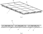
- FIG. 3 shows a solar module 25 according to the invention, which is connected to an alternative rear element 1", in a perspective view.
- Figure 4 shows the solar module 25 in a schematic sectional view.
- the embodiment variant of the rear side element 1" according to the invention differs by a third level 27, which is arranged between the first level 5 and the second level 7.
- a third level 27 which is arranged between the first level 5 and the second level 7.
Landscapes
- Photovoltaic Devices (AREA)
- Health & Medical Sciences (AREA)
- Life Sciences & Earth Sciences (AREA)
- Molecular Biology (AREA)
- Sustainable Development (AREA)
Claims (15)
- Un élément arrière (1, 1', 1") pour un module solaire (25), constitué d'une bande de matière (3) formée, découpée en sections, en particulier gaufrée et/ou poinçonnée, dans lequel la bande de matière (3) est disposée en sections dans un premier plan (5) et en sections dans au moins un deuxième plan (7) parallèle au premier plan (5), et dans lequel la bande de matière (3) forme des éléments d'espacement (9) dans la zone de transition du premier au deuxième plan (7) pour espacer le premier (5) du deuxième plan (7), et dans lequel au moins une première section de bande de matière (11, 11') s'étend continuellement, en particulier linéairement, d'un premier bord latéral à un deuxième bord latéral opposé de la bande de matière (3) dans le premier plan (5), dans lequel n premières sections de bande de matière (11, 11'), avec n = 1, 2, 3, 4, 5, 6, 7, 8, 9 ou plus, s'étendent d'un premier bord latéral à un deuxième bord latéral opposé de la bande de matière (3) dans le premier plan (5) et/ou m deuxièmes sections de bande de matière (13, 13'), avec m = 1, 2, 3, 4, 5, 6, 7, 8, 9 ou plus, s'étendent d'un troisième bord latéral de la bande matérielle (3) à un quatrième bord latéral opposé dans le premier plan (5), dans lequel les première et deuxième sections de bande de matière (11, 11', 13, 13') sont perpendiculaires l'une à l'autre, et dans lequel les sections de bande de matière créées à partir de la bande de matière (3) en formant et en coupant forment au moins en sections des ouvertures de l'élément arrière dans les zones où elles ne sont pas dans le même plan.
- L'élément arrière (1, 1', 1") selon la revendication 1, caractérisé en ce que les n premières sections d'bande de matière (11, 11') s'étendent continuellement d'un premier bord latéral à un deuxième bord latéral opposé de la bande de matière (3) dans le premier plan (5) et/ou les m deuxièmes sections de bande de matière (13, 13') s'étendent continuellement d'un troisième bord latéral de la bande de matière (3) à un quatrième bord latéral opposé dans le premier plan (5).
- L'élément arrière (1, 1', 1") selon l'une quelconque des revendications 1 ou 2, caractérisé en ce que le deuxième plan (7) comprend p, avec p = 1,2,3,4,5,6,7,8,9 ou plus, éléments plats qui sont espacés les uns des autres et qui sont disposés en particulier entre les n premières (11, 11') et/ou m deuxièmes sections de bande (13, 13') du premier plan (5).
- L'élément arrière (1, 1', 1") selon la revendication 3, caractérisé en ce que chacun des éléments plats du deuxième plan (7) est relié aux premières (11, 11') et/ou deuxièmes sections (13, 13') de bande de matière du premier plan (5) au moyen d'au moins un, en particulier quatre, élément d'espacement (9), dans lequel les éléments d'espacement (9) sont formés par formage de la bande de matière (3).
- L'élément arrière (1, 1', 1") selon la revendication 3 ou 4, caractérisé en ce que l'élément arrière (1, 1', 1") comporte q, avec q = 1 ,2,3,4,5,6,7,8,9 ou plus, cellules (23), chacune des q cellules (23) étant formée de deux premières sections de bande de matière (11, 11'), de deux deuxièmes sections de bande de matière (13, 13') dans le premier plan (5) et de l'élément plat dans le deuxième plan (7).
- L'élément arrière (1, 1', 1") selon la revendication 5, caractérisé en ce qu'une première première section de bande de matière (11) a une première extrémité latérale (15), une deuxième première section de bande de matière (11') a une deuxième extrémité latérale opposée à la première extrémité latérale (15), une première deuxième section de bande de matière (13) forme une troisième extrémité latérale (17) disposée perpendiculairement à la première (15) et à la deuxième extrémité latérale (13') et une deuxième deuxième section de bande de matière (13') forme une quatrième extrémité latérale opposée à la troisième extrémité latérale (17), dans lequel, en transformant, une première section de bande de matériau (3) est à partir de la deuxième deuxième section de bande de matière (13') à une première distance (21) parallèle à la première première section de bande de matière (11) jusqu'à un premier espacement (19) à la première deuxième section de bande de matière (13) et une deuxième section de bande de matière (3) est à partir de la deuxième deuxième section de bande de matière (13') à une deuxième distance (21') supérieure à la première distance (21) parallèle à la première première section de bande de matière (11) jusqu'à un deuxième espacement (19') supérieure au premier espacement (19) à la première deuxième section de bande de matière (13) et/ou, en transformant, une troisième section de bande de matière (3) est à partir de la première deuxième section de bande de matière (13) à une première distance parallèle à la deuxième première section de bande de matière (11') jusqu'à un premier espacement à la deuxième deuxième section de bande de matière (13') et une quatrième section de bande de matière est à partir de première deuxième section de bande de matière (13) à une deuxième distance, supérieure à la première distance, parallèle à la deuxième première section de bande de matière (11') jusqu'à un deuxième espacement, supérieure au premier espacement, à la deuxième deuxième section de bande de matière (13'), et/ou, en transformant, une cinquième section de bande de matière (3 est à partir de la première première section de bande de matière (11) à une première distance parallèle à la première deuxième section de bande de matière (13) jusqu'à un premier espacement à la deuxième première section de bande de matière (11') et une sixième section de bande de matière est à partir de la première première section de bande de matière (11) à une deuxième distance, supérieure à la première distance, parallèle à la première deuxième section de bande de matière (13) jusqu'à un deuxième espacement, supérieure au premier espacement, à la deuxième première section de bande de matière (11'), et/ou, en transformant, une septième section de bande de matière (3) est à partir de la deuxième première section de bande de matière (11') à une première distance parallèle à la deuxième deuxième section de bande de matière (13') jusqu'à un premier espacement à la première première section d'bande de matière (11) et une huitième section de bande de matière est à partir de la deuxième première section de bande de matière (11') à une deuxième distance, supérieure à la première distance, parallèle à la deuxième deuxième section de bande de matière (13') jusqu'à un deuxième espacement, supérieur au premier espacement, à la première première section de bande de matière (11), de sorte qu'au moins un, en particulier quatre, élément d'espacement (9) est formé pour espacer un élément plat des première (11, 11') et deuxième sections de bande de matière (13, 13') à l'intérieur de la cellule (23).
- L'élément arrière (1, 1', 1") selon l'une quelconque des revendications précédentes, caractérisé en ce que la bande de matière (3) consiste et/ou comprend du métal, de l'acier inoxydable, de la tôle d'acier, de la tôle, du cuivre, du laiton, de l'aluminium, du plastique, du plastique moulé par injection et/ou du métal partiellement surmoulé, et a en particulier une épaisseur dans une plage de 0,2 mm et 4 mm, de préférence dans une plage de 0,4 mm et 2 mm, particulièrement préférable dans une plage de 0,5 mm à 1 mm.
- L'élément arrière selon l'une quelconque des revendications précédentes, caractérisé en ce que l'élément arrière présente au moins un évidement ou une forme au premier plan et/ou au deuxième plan pour recevoir une boîte de jonction pour un contact électrique d'une cellule solaire et/ou d'une matrice de cellules solaires et/ou pour permettre un contact électrique d'une cellule solaire et/ou d'une matrice de cellules solaires, en particulier des zones des connecteurs transversaux d'une cellule solaire et/ou d'une matrice de cellules solaires exposées dans l'évidement et/ou que des œillets de retenue, des pinces, des guides câbles et/ou des conduits de câbles pour le contact électrique des cellules solaires sont inclus et/ou que l'élément arrière a des évidements dans la zone de bord afin de permettre le transport en toute sécurité des éléments de contact électrique, en particulier des câbles et/ou des fiches, et de simplifier/assurer leur fixation après l'installation du module solaire.
- L'élément arrière (1") selon l'une quelconque des revendications précédentes, caractérisé en ce que la bande de matière (3) comprend des éléments de renforcement, disposés en particulier dans la zone de liaison de l'élément arrière (1") avec une sous-structure et/ou que le deuxième plan (7), en particulier au moins un élément plat du deuxième plan (7), est transformé de telle sorte qu'un troisième plan (27) est formé et/ou a une structure de surface en relief, en particulier gaufrée, qui est en particulier en forme de nid d'abeille.
- L'élément arrière selon l'une quelconque des revendications précédentes, caractérisé en ce qu'au moins un bord extérieur, en particulier deux bords opposés, de préférence tous les bords, de l'élément arrière est ou sont transformés par pliage et forment en particulièrement un profil approprié au raidissement, en particulier un profil en caisson et/ou qu'au moins un bord extérieur, en particulier deux bords opposés, de préférence tous les bords, de l'élément arrière comprennent des évidements et/ou des formes qui peuvent être placés ou sont placés en contact actif avec des évidements et/ou des formes complémentaires d'un autre élément arrière, dans lequel les évidements et/ou les formes sont conçus et adaptés de manière à aligner deux éléments arrière l'un par rapport à l'autre et/ou qu'au moins un bord extérieur, en particulier deux bords opposés, de préférence tous les bords de l'élément arrière présentent des dispositifs de fixation et/ou des évidements, en particulier sous forme de trous, conçus et adaptés pour relier l'élément arrière à un autre élément et/ou à la sous-structure de manière non détachable ou détachable et/ou que l'élément arrière consiste d'une bande de matière transformé.
- Un module solaire (25) comprenant au moins deux cellules solaires et au moins un élément arrière (1") selon l'une quelconque des revendications précédentes et disposé à l'arrière des cellules solaires, dans lequel le deuxième plan (7) d'au moins un élément arrière (1") est disposé face à l'arrière des cellules solaires.
- Le module solaire (25) selon la revendication 11, caractérisé en ce que le module solaire (25) ne comprend pas de cadre de module et de système de montage comprenant des rails arrière.
- Le module solaire selon l'une quelconque des revendications 11 ou 12, caractérisé en ce que respectivement au moins un élément plat et/ou au moins une cellule, en particulier r éléments plats et/ou cellules, avec r = 1, 2, 3, 4, 5, 6, 7, 8, 9 ou plus, de préférence r = 1, 4, 9 ou 16, se chevauchent au moins partiellement, en particulier coïncident, dans le deuxième plan de l'élément arrière avec au moins une des cellules solaires de la matrice de cellules solaires du module solaire, de sorte que l'arrière de chacune des cellules solaires soit opposé à r éléments plats et/ou cellules, et/ou que l'élément arrière couvre tout l'arrière du module solairè ou au moins un ou plusieurs éléments arrière couvrent une partie de l'arrière du module solaire.
- Un procédé de fabrication d'un module solaire comprenant les étapes suivantes dans cet ordre :a) fournir un panneau de substrat ;b) disposer au moins deux cellules solaires en contact électrique sur le panneau de substrat ;c) disposer au moins une couche de stratifié arrière à l'arrière de la cellule solaire ;d) disposer au moins un élément arrière selon l'une des revendications 1 à 10 sur la couche stratifiée arrière ; ete) laminer le module solaire, comprenant optionnellement encore les étapes suivantes après l'étape e), en particulier dans cet ordre :f) ajuster le stratifié ; etg) fixer des boîtes de jonction pour la mise en contact électrique du module solaire.
- Un procédé de fabrication d'un module solaire comprenant les étapes suivantes dans cet ordre :aa) fournir un panneau de substrat ;ab) disposer au moins deux cellules solaires en contact électrique sur le panneau de substrat ;ac) disposer au moins une couche stratifié arrière à l'arrière de la cellule solaire ;ad) laminer au moins la couche stratifiée arrière ;ae) optionnellement ajuster le stratifié ;af) optionnellement fixer des boîtes de jonction pour la mise en contact électrique du module solaire et disposer au moins un élément arrière selon l'une des revendications 1 à 10 sur la couche stratifiée arrière et relier l'élément arrière avec la couche stratifiée arrière, en particulier au moyen d'un adhésif silicone oupolyuréthane ; ouag) disposer au moins un élément arrière selon l'une des revendications 1 à 10 sur la couche stratifiée arrière et relier l'élément arrière à la couche stratifiée arrière,en particulier au moyen d'un adhésif silicone ou polyuréthane, et fixer les boîtes de jonction pour la mise en contact électrique du module solaire.
Applications Claiming Priority (2)
| Application Number | Priority Date | Filing Date | Title |
|---|---|---|---|
| DE102015117793.5A DE102015117793A1 (de) | 2015-10-19 | 2015-10-19 | Rückseitenelement für ein Solarmodul |
| PCT/EP2016/074997 WO2017067940A1 (fr) | 2015-10-19 | 2016-10-18 | Élément arrière pour module solaire |
Publications (3)
| Publication Number | Publication Date |
|---|---|
| EP3365973A1 EP3365973A1 (fr) | 2018-08-29 |
| EP3365973C0 EP3365973C0 (fr) | 2024-08-14 |
| EP3365973B1 true EP3365973B1 (fr) | 2024-08-14 |
Family
ID=57153469
Family Applications (1)
| Application Number | Title | Priority Date | Filing Date |
|---|---|---|---|
| EP16784174.1A Active EP3365973B1 (fr) | 2015-10-19 | 2016-10-18 | Élément arrière pour module solaire |
Country Status (8)
| Country | Link |
|---|---|
| US (1) | US11004992B2 (fr) |
| EP (1) | EP3365973B1 (fr) |
| JP (1) | JP6726854B2 (fr) |
| KR (1) | KR102290125B1 (fr) |
| CN (1) | CN108141172B (fr) |
| AU (1) | AU2016341146B2 (fr) |
| DE (1) | DE102015117793A1 (fr) |
| WO (1) | WO2017067940A1 (fr) |
Families Citing this family (4)
| Publication number | Priority date | Publication date | Assignee | Title |
|---|---|---|---|---|
| US20190154305A1 (en) * | 2017-11-14 | 2019-05-23 | Quest Renewables, Llc | Apparatuses, systems, and methods for a self-balanced photovoltaic system |
| KR102251784B1 (ko) * | 2019-04-25 | 2021-05-14 | 한국에너지기술연구원 | 태양광 패널과 태양열 패널 통합을 위한 유연 모듈 |
| DE102020109118B3 (de) * | 2020-04-01 | 2021-03-25 | Matrix Module Gmbh | Abstandsstruktur, Sandwich-Konstruktion mit einer solchen Abstandsstruktur und Verfahren zur Herstellung einer solchen Abstandsstruktur |
| KR20240133217A (ko) * | 2023-02-28 | 2024-09-04 | 고려대학교 산학협력단 | 지지기판, 이를 포함하는 태양광 모듈 및 태양광 모듈의 제조방법 |
Family Cites Families (26)
| Publication number | Priority date | Publication date | Assignee | Title |
|---|---|---|---|---|
| DE3611543A1 (de) * | 1986-04-05 | 1987-10-08 | Remscheid Volksbank | Solarmodul |
| JP2651121B2 (ja) * | 1993-05-18 | 1997-09-10 | キヤノン株式会社 | 太陽電池モジュール及びその設置方法 |
| JP2000008567A (ja) | 1998-06-18 | 2000-01-11 | Canon Inc | 建材、固定具、建材構造物、太陽電池モジュール発電システム、および建材の固定方法 |
| JP2001053321A (ja) | 1999-08-13 | 2001-02-23 | Kanegafuchi Chem Ind Co Ltd | 太陽電池モデュール製品の製造方法 |
| WO2005029657A1 (fr) | 2003-09-19 | 2005-03-31 | The Furukawa Electric Co., Ltd. | Module pile solaire et elements constituants |
| EP1751795A4 (fr) * | 2004-06-04 | 2007-08-29 | Automation Tooling Syst | Procede de construction de modules photovoltaiques rigides |
| DE212004000096U1 (de) * | 2004-12-01 | 2007-07-05 | Hakemann, Fritz | Verbundplatte |
| DE102005057468A1 (de) * | 2005-11-30 | 2007-05-31 | Solarwatt Solar-Systeme Ag | Photovoltaisches rahmenloses Solarmodul in Plattenform |
| DE102006004626A1 (de) * | 2006-01-31 | 2007-08-02 | Triplex Kunststoffe Gmbh | Bauelement |
| US20090114268A1 (en) * | 2006-11-15 | 2009-05-07 | Solyndra, Inc. | Reinforced solar cell frames |
| WO2009143577A1 (fr) * | 2008-05-30 | 2009-12-03 | Ross Allan Edgar | Réseaux solaires tridimensionnels |
| DE202008013755U1 (de) * | 2008-07-04 | 2009-03-05 | Signet Solar Gmbh | Flächiges Verstärkungs- oder Stabilisierungselement und Befestigungsvorrichtung für ein Photovoltaikmodul |
| US20100031996A1 (en) * | 2008-08-11 | 2010-02-11 | Basol Bulent M | Structure and method of manufacturing thin film photovoltaic modules |
| US20100126554A1 (en) * | 2008-09-04 | 2010-05-27 | Morgan Solar Inc. | Staggered light collectors for concentrator solar panels |
| DE102009020426A1 (de) * | 2009-05-08 | 2010-11-11 | Gehrlicher Solar Ag | Stabiles Photovoltaik-Solarmodul aus zwei über einen Spacer verbundenen Platten und dazu passende Montagesysteme |
| US8302363B1 (en) * | 2009-05-12 | 2012-11-06 | Ebert Composites Corporation | Composite interlocking structure |
| NL2004065C2 (en) | 2010-01-06 | 2011-07-07 | Stichting Energie | Solar panel module and method for manufacturing such a solar panel module. |
| FR2967817B1 (fr) * | 2010-11-22 | 2013-08-16 | Solaire 2G | Panneau solaire hybride. |
| CN201853724U (zh) * | 2010-11-30 | 2011-06-01 | 东莞南玻太阳能玻璃有限公司 | 一种太阳能电池组件 |
| KR101037207B1 (ko) * | 2011-01-12 | 2011-05-26 | 두원산업(주) | 태양전지 모듈 지지대 |
| US8365479B2 (en) * | 2011-06-17 | 2013-02-05 | Phat Energy Corporation | Solar power structure |
| US10090799B2 (en) | 2012-01-10 | 2018-10-02 | Pvilion, Inc. | Tensioned sheet-metal based solar panels and structures for supporting the same |
| US9780253B2 (en) * | 2014-05-27 | 2017-10-03 | Sunpower Corporation | Shingled solar cell module |
| US20140196770A1 (en) * | 2013-01-17 | 2014-07-17 | University Of Central Florida Research Foundation, Inc. | Photovoltaic module and system |
| DE102013220802A1 (de) | 2013-10-15 | 2015-04-16 | SolarWorld Industries Thüringen GmbH | Solarmodul und Verfahren zum Herstellen eines Solarmoduls |
| US20170179321A1 (en) * | 2015-12-21 | 2017-06-22 | Lazar Izardel | Array of unequally shaped solar panels |
-
2015
- 2015-10-19 DE DE102015117793.5A patent/DE102015117793A1/de active Pending
-
2016
- 2016-10-18 US US15/769,083 patent/US11004992B2/en active Active
- 2016-10-18 EP EP16784174.1A patent/EP3365973B1/fr active Active
- 2016-10-18 KR KR1020187013887A patent/KR102290125B1/ko active Active
- 2016-10-18 JP JP2018521305A patent/JP6726854B2/ja active Active
- 2016-10-18 CN CN201680061009.0A patent/CN108141172B/zh active Active
- 2016-10-18 WO PCT/EP2016/074997 patent/WO2017067940A1/fr not_active Ceased
- 2016-10-18 AU AU2016341146A patent/AU2016341146B2/en active Active
Also Published As
| Publication number | Publication date |
|---|---|
| CN108141172B (zh) | 2020-06-30 |
| KR102290125B1 (ko) | 2021-08-13 |
| AU2016341146B2 (en) | 2020-03-12 |
| EP3365973C0 (fr) | 2024-08-14 |
| DE102015117793A1 (de) | 2017-04-20 |
| JP2018531523A (ja) | 2018-10-25 |
| JP6726854B2 (ja) | 2020-07-22 |
| WO2017067940A1 (fr) | 2017-04-27 |
| EP3365973A1 (fr) | 2018-08-29 |
| AU2016341146A1 (en) | 2018-06-07 |
| US11004992B2 (en) | 2021-05-11 |
| CN108141172A (zh) | 2018-06-08 |
| US20180309004A1 (en) | 2018-10-25 |
| KR20180071311A (ko) | 2018-06-27 |
Similar Documents
| Publication | Publication Date | Title |
|---|---|---|
| EP2093805B1 (fr) | Module photovoltaïque doté d'une protection contre l'aspiration par le vent | |
| EP3365973B1 (fr) | Élément arrière pour module solaire | |
| EP3497381B1 (fr) | Module thermique photovoltaïque à échangeur de chaleur par air | |
| WO2007144113A1 (fr) | Élément solaire avec dispositif de régulation de température | |
| DE102008051249A1 (de) | Photovoltaikanlage, Photovoltaikmodul und Verfahren zur Bestückung einer Photovoltaikanlage | |
| DE112012001993T5 (de) | Solarbatteriesystem und Solarbatteriemodul | |
| EP4591428A1 (fr) | Module photovoltaïque-thermique | |
| EP2159847B1 (fr) | Système comprenant un module solaire à couche fine sans cadre et une pince de fixation | |
| DE102011122126A1 (de) | Solarmodul | |
| DE102009035644A1 (de) | Anordnung und Verfahren zur Verringerung der Durchbiegung der durch einen Rahmen eingefassten Laminate von Photovoltaik-Modulen | |
| DE102010001016A1 (de) | Anschlusseinheit für Photovoltaische Module | |
| JP2018531523A6 (ja) | ソーラーモジュール用裏面部材 | |
| EP2109153A2 (fr) | Elément solaire pour installations solaires | |
| WO2014075919A1 (fr) | Module photovoltaïque pourvu d'une tôle de renfort arrière | |
| DE202011102874U1 (de) | Sonnenschutzvorrichtung mit Solarelement | |
| WO2009086803A2 (fr) | Élément photovoltaïque, structure support, procédé de montage d'une structure support, et centrale électrique correspondante | |
| EP2811239B1 (fr) | Entretoise | |
| EP2746694A1 (fr) | Agencement thermique, procédé de fabrication d'un agencement thermique et procédé de montage d'un agencement thermique | |
| DE202011109473U1 (de) | Solarmodul | |
| EP3715745A1 (fr) | Système de fixation pour un système de module solaire hybride ainsi que système de module solaire hybride et procédé de fixation | |
| DE102013208608B3 (de) | Solarthermischer Flachkollektor, Verfahren zu dessen Herstellung, sowie Montagerahmen zur Durchführung des Verfahrens | |
| DE102022123134B4 (de) | Photothermie-Modul | |
| EP2685200B1 (fr) | Conduction carrier with foamed metallic core and method for its production | |
| DE102013010407A1 (de) | Solarmodul mit Rückseitenverstärkung | |
| DE102017222720A1 (de) | Kühlanordnung, Leistungselektronikvorrichtung mit einer Kühlanordnung, Verfahren zum Herstellen einer Kühlanordnung |
Legal Events
| Date | Code | Title | Description |
|---|---|---|---|
| STAA | Information on the status of an ep patent application or granted ep patent |
Free format text: STATUS: THE INTERNATIONAL PUBLICATION HAS BEEN MADE |
|
| PUAI | Public reference made under article 153(3) epc to a published international application that has entered the european phase |
Free format text: ORIGINAL CODE: 0009012 |
|
| STAA | Information on the status of an ep patent application or granted ep patent |
Free format text: STATUS: REQUEST FOR EXAMINATION WAS MADE |
|
| 17P | Request for examination filed |
Effective date: 20180517 |
|
| AK | Designated contracting states |
Kind code of ref document: A1 Designated state(s): AL AT BE BG CH CY CZ DE DK EE ES FI FR GB GR HR HU IE IS IT LI LT LU LV MC MK MT NL NO PL PT RO RS SE SI SK SM TR |
|
| AX | Request for extension of the european patent |
Extension state: BA ME |
|
| DAV | Request for validation of the european patent (deleted) | ||
| DAX | Request for extension of the european patent (deleted) | ||
| STAA | Information on the status of an ep patent application or granted ep patent |
Free format text: STATUS: EXAMINATION IS IN PROGRESS |
|
| 17Q | First examination report despatched |
Effective date: 20190225 |
|
| RAP1 | Party data changed (applicant data changed or rights of an application transferred) |
Owner name: MATRIX MODULE GMBH |
|
| GRAP | Despatch of communication of intention to grant a patent |
Free format text: ORIGINAL CODE: EPIDOSNIGR1 |
|
| STAA | Information on the status of an ep patent application or granted ep patent |
Free format text: STATUS: GRANT OF PATENT IS INTENDED |
|
| INTG | Intention to grant announced |
Effective date: 20210706 |
|
| GRAJ | Information related to disapproval of communication of intention to grant by the applicant or resumption of examination proceedings by the epo deleted |
Free format text: ORIGINAL CODE: EPIDOSDIGR1 |
|
| STAA | Information on the status of an ep patent application or granted ep patent |
Free format text: STATUS: EXAMINATION IS IN PROGRESS |
|
| INTC | Intention to grant announced (deleted) | ||
| GRAP | Despatch of communication of intention to grant a patent |
Free format text: ORIGINAL CODE: EPIDOSNIGR1 |
|
| STAA | Information on the status of an ep patent application or granted ep patent |
Free format text: STATUS: GRANT OF PATENT IS INTENDED |
|
| INTG | Intention to grant announced |
Effective date: 20240228 |
|
| GRAS | Grant fee paid |
Free format text: ORIGINAL CODE: EPIDOSNIGR3 |
|
| GRAA | (expected) grant |
Free format text: ORIGINAL CODE: 0009210 |
|
| STAA | Information on the status of an ep patent application or granted ep patent |
Free format text: STATUS: THE PATENT HAS BEEN GRANTED |
|
| AK | Designated contracting states |
Kind code of ref document: B1 Designated state(s): AL AT BE BG CH CY CZ DE DK EE ES FI FR GB GR HR HU IE IS IT LI LT LU LV MC MK MT NL NO PL PT RO RS SE SI SK SM TR |
|
| REG | Reference to a national code |
Ref country code: GB Ref legal event code: FG4D Free format text: NOT ENGLISH |
|
| REG | Reference to a national code |
Ref country code: CH Ref legal event code: EP |
|
| REG | Reference to a national code |
Ref country code: DE Ref legal event code: R096 Ref document number: 502016016669 Country of ref document: DE |
|
| REG | Reference to a national code |
Ref country code: IE Ref legal event code: FG4D Free format text: LANGUAGE OF EP DOCUMENT: GERMAN |
|
| U01 | Request for unitary effect filed |
Effective date: 20240913 |
|
| U07 | Unitary effect registered |
Designated state(s): AT BE BG DE DK EE FI FR IT LT LU LV MT NL PT RO SE SI Effective date: 20240925 |
|
| U20 | Renewal fee for the european patent with unitary effect paid |
Year of fee payment: 9 Effective date: 20241022 |
|
| PG25 | Lapsed in a contracting state [announced via postgrant information from national office to epo] |
Ref country code: NO Free format text: LAPSE BECAUSE OF FAILURE TO SUBMIT A TRANSLATION OF THE DESCRIPTION OR TO PAY THE FEE WITHIN THE PRESCRIBED TIME-LIMIT Effective date: 20241114 |
|
| PG25 | Lapsed in a contracting state [announced via postgrant information from national office to epo] |
Ref country code: GR Free format text: LAPSE BECAUSE OF FAILURE TO SUBMIT A TRANSLATION OF THE DESCRIPTION OR TO PAY THE FEE WITHIN THE PRESCRIBED TIME-LIMIT Effective date: 20241115 Ref country code: PL Free format text: LAPSE BECAUSE OF FAILURE TO SUBMIT A TRANSLATION OF THE DESCRIPTION OR TO PAY THE FEE WITHIN THE PRESCRIBED TIME-LIMIT Effective date: 20240814 |
|
| PG25 | Lapsed in a contracting state [announced via postgrant information from national office to epo] |
Ref country code: IS Free format text: LAPSE BECAUSE OF FAILURE TO SUBMIT A TRANSLATION OF THE DESCRIPTION OR TO PAY THE FEE WITHIN THE PRESCRIBED TIME-LIMIT Effective date: 20241214 |
|
| PG25 | Lapsed in a contracting state [announced via postgrant information from national office to epo] |
Ref country code: HR Free format text: LAPSE BECAUSE OF FAILURE TO SUBMIT A TRANSLATION OF THE DESCRIPTION OR TO PAY THE FEE WITHIN THE PRESCRIBED TIME-LIMIT Effective date: 20240814 |
|
| PG25 | Lapsed in a contracting state [announced via postgrant information from national office to epo] |
Ref country code: RS Free format text: LAPSE BECAUSE OF FAILURE TO SUBMIT A TRANSLATION OF THE DESCRIPTION OR TO PAY THE FEE WITHIN THE PRESCRIBED TIME-LIMIT Effective date: 20241114 Ref country code: ES Free format text: LAPSE BECAUSE OF FAILURE TO SUBMIT A TRANSLATION OF THE DESCRIPTION OR TO PAY THE FEE WITHIN THE PRESCRIBED TIME-LIMIT Effective date: 20240814 |
|
| PG25 | Lapsed in a contracting state [announced via postgrant information from national office to epo] |
Ref country code: RS Free format text: LAPSE BECAUSE OF FAILURE TO SUBMIT A TRANSLATION OF THE DESCRIPTION OR TO PAY THE FEE WITHIN THE PRESCRIBED TIME-LIMIT Effective date: 20241114 Ref country code: PL Free format text: LAPSE BECAUSE OF FAILURE TO SUBMIT A TRANSLATION OF THE DESCRIPTION OR TO PAY THE FEE WITHIN THE PRESCRIBED TIME-LIMIT Effective date: 20240814 Ref country code: NO Free format text: LAPSE BECAUSE OF FAILURE TO SUBMIT A TRANSLATION OF THE DESCRIPTION OR TO PAY THE FEE WITHIN THE PRESCRIBED TIME-LIMIT Effective date: 20241114 Ref country code: IS Free format text: LAPSE BECAUSE OF FAILURE TO SUBMIT A TRANSLATION OF THE DESCRIPTION OR TO PAY THE FEE WITHIN THE PRESCRIBED TIME-LIMIT Effective date: 20241214 Ref country code: HR Free format text: LAPSE BECAUSE OF FAILURE TO SUBMIT A TRANSLATION OF THE DESCRIPTION OR TO PAY THE FEE WITHIN THE PRESCRIBED TIME-LIMIT Effective date: 20240814 Ref country code: GR Free format text: LAPSE BECAUSE OF FAILURE TO SUBMIT A TRANSLATION OF THE DESCRIPTION OR TO PAY THE FEE WITHIN THE PRESCRIBED TIME-LIMIT Effective date: 20241115 Ref country code: ES Free format text: LAPSE BECAUSE OF FAILURE TO SUBMIT A TRANSLATION OF THE DESCRIPTION OR TO PAY THE FEE WITHIN THE PRESCRIBED TIME-LIMIT Effective date: 20240814 |
|
| PG25 | Lapsed in a contracting state [announced via postgrant information from national office to epo] |
Ref country code: SM Free format text: LAPSE BECAUSE OF FAILURE TO SUBMIT A TRANSLATION OF THE DESCRIPTION OR TO PAY THE FEE WITHIN THE PRESCRIBED TIME-LIMIT Effective date: 20240814 |
|
| PG25 | Lapsed in a contracting state [announced via postgrant information from national office to epo] |
Ref country code: CZ Free format text: LAPSE BECAUSE OF FAILURE TO SUBMIT A TRANSLATION OF THE DESCRIPTION OR TO PAY THE FEE WITHIN THE PRESCRIBED TIME-LIMIT Effective date: 20240814 |
|
| PG25 | Lapsed in a contracting state [announced via postgrant information from national office to epo] |
Ref country code: SK Free format text: LAPSE BECAUSE OF FAILURE TO SUBMIT A TRANSLATION OF THE DESCRIPTION OR TO PAY THE FEE WITHIN THE PRESCRIBED TIME-LIMIT Effective date: 20240814 |
|
| REG | Reference to a national code |
Ref country code: CH Ref legal event code: PL |
|
| PLBE | No opposition filed within time limit |
Free format text: ORIGINAL CODE: 0009261 |
|
| STAA | Information on the status of an ep patent application or granted ep patent |
Free format text: STATUS: NO OPPOSITION FILED WITHIN TIME LIMIT |
|
| PG25 | Lapsed in a contracting state [announced via postgrant information from national office to epo] |
Ref country code: MC Free format text: LAPSE BECAUSE OF FAILURE TO SUBMIT A TRANSLATION OF THE DESCRIPTION OR TO PAY THE FEE WITHIN THE PRESCRIBED TIME-LIMIT Effective date: 20240814 |
|
| 26N | No opposition filed |
Effective date: 20250515 |
|
| GBPC | Gb: european patent ceased through non-payment of renewal fee |
Effective date: 20241114 |
|
| PG25 | Lapsed in a contracting state [announced via postgrant information from national office to epo] |
Ref country code: CH Free format text: LAPSE BECAUSE OF NON-PAYMENT OF DUE FEES Effective date: 20241031 |
|
| PG25 | Lapsed in a contracting state [announced via postgrant information from national office to epo] |
Ref country code: GB Free format text: LAPSE BECAUSE OF NON-PAYMENT OF DUE FEES Effective date: 20241114 |
|
| PG25 | Lapsed in a contracting state [announced via postgrant information from national office to epo] |
Ref country code: IE Free format text: LAPSE BECAUSE OF NON-PAYMENT OF DUE FEES Effective date: 20241018 |
|
| U20 | Renewal fee for the european patent with unitary effect paid |
Year of fee payment: 10 Effective date: 20251023 |
|
| PG25 | Lapsed in a contracting state [announced via postgrant information from national office to epo] |
Ref country code: CY Free format text: LAPSE BECAUSE OF FAILURE TO SUBMIT A TRANSLATION OF THE DESCRIPTION OR TO PAY THE FEE WITHIN THE PRESCRIBED TIME-LIMIT; INVALID AB INITIO Effective date: 20161018 |
|
| PG25 | Lapsed in a contracting state [announced via postgrant information from national office to epo] |
Ref country code: HU Free format text: LAPSE BECAUSE OF FAILURE TO SUBMIT A TRANSLATION OF THE DESCRIPTION OR TO PAY THE FEE WITHIN THE PRESCRIBED TIME-LIMIT; INVALID AB INITIO Effective date: 20161018 |