EP3366256A2 - Dispositif de guidage d'une fraise creuse de chirurgie dentaire et procédé de fabrication d'un tel dispositif - Google Patents
Dispositif de guidage d'une fraise creuse de chirurgie dentaire et procédé de fabrication d'un tel dispositif Download PDFInfo
- Publication number
- EP3366256A2 EP3366256A2 EP18157381.7A EP18157381A EP3366256A2 EP 3366256 A2 EP3366256 A2 EP 3366256A2 EP 18157381 A EP18157381 A EP 18157381A EP 3366256 A2 EP3366256 A2 EP 3366256A2
- Authority
- EP
- European Patent Office
- Prior art keywords
- template
- guide means
- bone
- hollow
- guide
- Prior art date
- Legal status (The legal status is an assumption and is not a legal conclusion. Google has not performed a legal analysis and makes no representation as to the accuracy of the status listed.)
- Granted
Links
Images







Classifications
-
- A—HUMAN NECESSITIES
- A61—MEDICAL OR VETERINARY SCIENCE; HYGIENE
- A61C—DENTISTRY; APPARATUS OR METHODS FOR ORAL OR DENTAL HYGIENE
- A61C1/00—Dental machines for boring or cutting ; General features of dental machines or apparatus, e.g. hand-piece design
- A61C1/08—Machine parts specially adapted for dentistry
- A61C1/082—Positioning or guiding, e.g. of drills
-
- A—HUMAN NECESSITIES
- A61—MEDICAL OR VETERINARY SCIENCE; HYGIENE
- A61B—DIAGNOSIS; SURGERY; IDENTIFICATION
- A61B17/00—Surgical instruments, devices or methods
- A61B17/16—Instruments for performing osteoclasis; Drills or chisels for bones; Trepans
- A61B17/17—Guides or aligning means for drills, mills, pins or wires
- A61B17/1739—Guides or aligning means for drills, mills, pins or wires specially adapted for particular parts of the body
- A61B17/176—Guides or aligning means for drills, mills, pins or wires specially adapted for particular parts of the body for the jaw
-
- A—HUMAN NECESSITIES
- A61—MEDICAL OR VETERINARY SCIENCE; HYGIENE
- A61C—DENTISTRY; APPARATUS OR METHODS FOR ORAL OR DENTAL HYGIENE
- A61C8/00—Means to be fixed to the jaw-bone for consolidating natural teeth or for fixing dental prostheses thereon; Dental implants; Implanting tools
- A61C8/0089—Implanting tools or instruments
-
- A—HUMAN NECESSITIES
- A61—MEDICAL OR VETERINARY SCIENCE; HYGIENE
- A61B—DIAGNOSIS; SURGERY; IDENTIFICATION
- A61B17/00—Surgical instruments, devices or methods
- A61B17/16—Instruments for performing osteoclasis; Drills or chisels for bones; Trepans
- A61B17/1635—Instruments for performing osteoclasis; Drills or chisels for bones; Trepans for grafts, harvesting or transplants
-
- A—HUMAN NECESSITIES
- A61—MEDICAL OR VETERINARY SCIENCE; HYGIENE
- A61C—DENTISTRY; APPARATUS OR METHODS FOR ORAL OR DENTAL HYGIENE
- A61C8/00—Means to be fixed to the jaw-bone for consolidating natural teeth or for fixing dental prostheses thereon; Dental implants; Implanting tools
- A61C8/0003—Not used, see subgroups
- A61C8/0004—Consolidating natural teeth
- A61C8/0006—Periodontal tissue or bone regeneration
-
- B—PERFORMING OPERATIONS; TRANSPORTING
- B33—ADDITIVE MANUFACTURING TECHNOLOGY
- B33Y—ADDITIVE MANUFACTURING, i.e. MANUFACTURING OF THREE-DIMENSIONAL [3D] OBJECTS BY ADDITIVE DEPOSITION, ADDITIVE AGGLOMERATION OR ADDITIVE LAYERING, e.g. BY 3D PRINTING, STEREOLITHOGRAPHY OR SELECTIVE LASER SINTERING
- B33Y50/00—Data acquisition or data processing for additive manufacturing
Definitions
- the present invention relates to a device for guiding a dental surgical hollow milling machine during bone removal. Furthermore, the present invention relates to a guide means and a template for such a device. Furthermore, the invention relates to a method for producing a device according to the invention.
- Autologous, patient-specific bone is still considered the gold standard in bone-building procedures. This is due to the properties of the bone, since autologous bone combines osteogenic, osteoinductive and osteoconductive properties. This means that the bone has the potential to form its own bone tissue, to form vessels and also acts as a guide for newly formed bones. In contrast to autologous bone, bone substitute material has no biological potency and acts only osteoconductive, that is, it also acts as a guide rail.
- the second intraoral removal site is always toothless bone areas, alternatively the maxillary tuberosity, the anterior nasal spine, the palate, the area of the maxillary sinus wall or the lower jaw, as this is more of a cortical nature and the bone quality is very good and stable.
- the lower jaw there are various bone removal sites, for example toothless areas, the chin or the retromolar area.
- Bone extraction can be done with different instruments.
- the concept of bone removal is usually similar.
- Trepanfräse or hollow milling is infected with a handpiece and having a head which is designed as a hollow cylinder. At the distal edge of the head teeth are formed for machining the bone.
- Trepan milling or hollow milling are used, for example, for implant bed preparation and have a diameter of about 3 mm to 4 mm. With the help of these milling extremely small and narrow drill cylinders are removed, which are only partially suitable for bone structure.
- the present invention is therefore based on the object of specifying a device so that a reliable and gentle to the patient bone removal is possible with structurally simple means. Furthermore, a method for producing such a device is to be specified.
- a device for guiding a dental surgical hollow milling machine in a bone removal is specified, with a fixable in the region of a donor template and at least one of the Template arranged guide means, wherein the guide means guides the hollow cutter such that only a part of the distal edge of the hollow cutter is brought into contact with the bone.
- the underlying object can be achieved in a sophisticated manner by means of a template with a guide means for guiding a dental surgical hollow milling machine.
- the template can be fixed in the area of the extraction point.
- a guide means is arranged, which guides the hollow cutter at a precisely defined angle to the removal point, so that the rotary hollow cutter can be brought into contact with the bone for bone removal only with a part of the distal edge.
- the hollow milling machine can be guided laterally along the bone so that a bone segment-shaped piece of bone is triggered. This ensures that the hollow milling machine can be introduced into the removal site by the surgeon in a guided movement, in particular at an exact angle.
- a hollow cutter is not only suitable for the removal of small cylinders. Rather, a correspondingly designed hollow milling machine can be used to "peel out” the required piece of bone or bone segment from the bone. Because of the guide means arranged on the template, the hollow milling machine can be brought into contact with the bone of the removal point in just such a manner. In other words, only a circular arc of the distal edge of the head of the hollow cutter can be brought into contact with the bone and thus serves as an effective effective range. In contrast to the instruments or tools known from the prior art, it is not necessary to apply three to four cuts or predetermined breaking points.
- the distal edge of the hollow cutter is the area of the hollow cylindrical head of the hollow cutter with which the bone is working, i.e., the hollow. milled, ground or cut.
- the term “hollow milling machine” is to be understood in the broadest sense, this may, for example. Saw teeth and / or a diamond in the effective range and be coupled to a dental handpiece to be set in rotation.
- the "sampling site” is the area of the bone from which the required piece of bone is cut out.
- the "bone deficit” is the area of the bone that is to be rebuilt by the removed bone segment.
- the template can be formed positively and / or non-positively fixed in the upper jaw and / or in the lower jaw. It is conceivable that the template is at least partially formed as a rail and / or can be fixed by holding pins or screws. In general, the template may be bone-worn and / or tooth-supported and / or mucosa-supported. It is also conceivable that the template is fixed via an external fixing device, which rests, for example, on the head of the patient.
- a plurality of guide means can be formed on the template.
- the hollow milling machine can be brought into contact with the bone through the guide means at different removal points.
- the guide means may surround the hollow milling machine in such a way that the tissue surrounding the removal point does not come into contact with the hollow milling machine.
- the guide means serves not only to bring the hollow cutter in a defined position with the bone in contact, but also as a protective element which shields the surrounding tissue against the hollow cutter.
- the guide means may be formed as a guide sleeve, in which the hollow cutter can be introduced.
- the guide sleeve may have a lateral opening, so that a part of the distal edge of the hollow cutter through the Opening the guide sleeve through with the bone can be brought into contact.
- the design of the guide means as a guide sleeve, the surrounding soft tissue is optimally protected from injury by the hollow cutter.
- guide sleeve is to be understood in the broadest sense.
- the guide sleeve does not necessarily have to be round or formed as part of a circular cylinder, namely, it may also have an at least partially angular geometry.
- the guide sleeve may be closed at its end region, thus has a bottom. This ensures once again that the surrounding tissue is protected.
- the hollow cutter has a spacer element which corresponds to the inner diameter of the guide sleeve and which is rotatably coupled to the hollow cutter. Thereby, the hollow cutter is rotatable in the guide sleeve and it is avoided that the distal edge of the hollow cutter comes into contact with the guide sleeve.
- the guide means may have a, in particular substantially cylindrical, receptacle for a corresponding guide element of the hollow milling machine.
- the guide element of the hollow milling machine may, for example, be a guide pin extending in the axial direction from the bottom of the head of the hollow milling machine.
- the receptacle can be designed as a sleeve or tube corresponding to the guide pin.
- the guide means of the template can be brought into engagement with a corresponding guide element of the hollow milling machine.
- a guide element rotatably coupled to the hollow milling machine, in particular a rail may be provided which corresponds to the guide means, for example a rail.
- a depth stop in the sense of a deep stop for the hollow milling machine can be formed on the guide means.
- the guide means in particular the guide sleeve, be releasably connected to the template.
- the guide means in particular the guide sleeve
- the template be provided with each other corresponding coupling elements over which the guide means at the desired angle to the template can be fixed.
- the corresponding coupling elements may be formed, for example, as a die and male.
- coupling elements can be provided on different areas of the template, so that the guide means can be fixed to the template at different angles of the base element in each case required angle and thus bone removal can take place at different sampling points.
- the guide means in particular the guide sleeve, is designed in one piece with the template or is an integral part of the template, for example glued to it, welded, etc.
- a plurality of guide means, in particular guide sleeves, may be provided on different regions of the base element.
- the template may comprise a holding means to hold the removed bone piece in the region of a bone deficit to be established.
- the bone piece can be positively and / or non-positively connectable with the template in the concrete, for example clipped or clamped in this. This makes it possible for the surgeon to fix the bone piece in the desired position in the region of the bone deficit, in particular to screw it to the jawbone to be erected.
- the guide means in particular the guide sleeve, be arranged or formed such that a hollow cutter can be used with the template according to the invention, whose head has an outer diameter of 5 mm to 11 mm, preferably 6 mm to 8 mm, and / or a depth of 6 mm to 17 mm, in particular 9 mm to 14 mm.
- the guide means in particular the guide sleeve, can be arranged or designed such that the arc of the distal edge of the hollow milling machine which can be brought into contact with the bone forms a circle segment having a segment height of 2.0 mm to 3.5 mm , preferably from 2.2 mm to 2.5 mm.
- a guide means for a device according to one of claims 1 to 9 is given, with a coupling element for releasable attachment to a template.
- the coupling element can also be a defined region of the guide means, which is glued or screwed to the template or otherwise attachable to the latter.
- the coupling element may be a die or male part, which can be brought into engagement with a corresponding male or female part of the template.
- a template according to claim 11 Thereafter, a template for a device according to one of claims 1 to 9 is given, with a coupling element for releasably securing a guide means.
- the coupling element can also be a defined region of the template, with which the guide means is glued or screwed or otherwise can be fastened thereto.
- the coupling element can be a die or a male part, which can be brought into engagement with a corresponding male or female part of the guide means.
- the guide means and / or the template may be designed according to the guide means described in claims 1 to 9 or the template described therein and have the features and advantages mentioned above with respect to this guide means or this template. Furthermore, the guide means according to claim 10 and the template according to claim 11 may have individual or all features of the guide means described in the following description of the figures or the template described.
- a three-dimensional, imaging procedure is first carried out at the removal site and possibly at the bone deficit.
- the donor site may be, in particular, the upper and / or lower jaw.
- a three-dimensional computer model of the removal site and possibly the bone deficit is generated in a further inventive manner.
- This has the advantage that the bone removal is virtually plannable, especially taking into account the individual anatomy of the patient, such as the course of nerves, root canals, etc.
- the patient-specific template is then planned or generated in a further inventive manner.
- the removal point and thus the positioning of the guide means can be determined exactly.
- the template can be produced by means of a rapid prototyping method, in particular a stereolithography method or a 3D printing method. Any method suitable for this purpose and known in particular in dental technology can be used.
- the guide means is formed integrally with the template, this can be generated in the same step together with the template, namely on the basis of the three-dimensional computer model.
- the coupling elements can be generated on the basis of the three-dimensional computer model on the template, so that the guide means with corresponding coupling elements in the desired, defined position on the template can be fixed.
- a computer tomography and / or a magnetic resonance tomography and / or a digital volume tomography can be used as a three-dimensional, imaging method.
- the invention further relates to a dental surgical hollow milling machine, wherein a spacer element is rotatably coupled to the hollow milling machine. This ensures that the hollow milling machine can not be brought into contact with the guide means according to the invention.
- the hollow milling machine according to the invention can advantageously have the features or individual features disclosed in the following description of the figures and the corresponding figures.
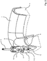
- a first embodiment of a device according to the invention is shown.
- the device has a template 1, on which a guide means 2 for a hollow cutter 3 is formed.
- a jaw bone 4 is shown on or on which the template 1 is arranged.
- the template 1 can not necessarily rest on the jaw bone 4, but alternatively or additionally to the existing teeth, the gums, etc.
- the guide means 2 is provided on the template 1, that only a part of the distal edge 5 of the hollow cutter 3 in a defined position with the bone 4 at the sampling point 6 can be brought into contact.
- the guide means 2 is designed such that the hollow cutter 3 is guided laterally along the jawbone 4.
- the guide means 2 is formed as a guide sleeve 7, wherein the guide sleeve 7 is not completely closed.
- the guide sleeve 7 serves in addition to the leadership of the hollow cutter 3 in addition to protect the surrounding tissue and may also be formed closed, with an opening 8 must be provided, through which the hollow cutter 3 with the bone 4 can be brought into contact.
- the inner diameter of the guide sleeve 7 is preferably to be dimensioned such that the rotating hollow cutter 3 does not come into contact with the guide sleeve 7.
- the guide means 2 comprises a cylindrical receptacle 9, which is realized as a circular cylinder or tube and serves for introducing a running within the head 10 of the hollow cutter 3 guide member 11 and guide pin.
- the receptacle 9 thus acts as a positive guide for the hollow cutter 3.
- the guide means 2 is not necessarily the guide sleeve 7 must have, but can be realized only by the receptacle 9.
- the guide means 2 can be designed releasably with the template 1. Furthermore, a depth stop 12 is formed, which serves as a depth stop, so that the hollow cutter 3 can be introduced into the jawbone 4 only over a defined length.
- the guide means 2 is formed as in the direction of the surrounding tissue closed guide sleeve 7, wherein the guide sleeve 7 is opened laterally in the direction of the removal point 6.
- a part of the distal edge 5 can process the bone 4.
- the guide sleeve 7 is formed integrally with the base member 1.
- the guide sleeve 7 may have coupling elements, via which it is releasably connected to the base element 1.
- the hollow cutter 3 is rotatably coupled to a protective device 13 and together with the protective device 13 in the guide sleeve 7 can be introduced.
- the protective device 13 has a lateral opening and serves as a spacer element 14, so that the head 10 does not come into contact with the guide sleeve 7 or the template 1.
- the guide sleeve 7 need not necessarily be formed closed. It is sufficient if the guide sleeve 7 surrounds the protective device 13 only partially.
- the embodiment corresponds to the Fig. 3 and 4 in the Fig. 1 and 2 shown embodiment, so that reference is made to avoid repetition of the above statements.
- the guide means 2 of the template 1 is realized by two rails 15 and matrices.
- the hollow milling machine 3 is rotatably coupled to a protective device 13, 13 guide elements 11 are formed as rails 16 and patricks on the protective device, which correspond to the rails 15 of the template 1.
- the hollow cutter 3 is above the rails 15, 16 guided.
- the hollow cutter 3 is rotatably connected to a spacer element 14.
- the outer diameter of the spacer element 14 corresponds approximately to the inner diameter of the guide sleeve 7.
- the spacer element 14 prevents the head 10 from coming into contact with the guide sleeve 7.
- the spacer element 14 has a bottom element 17 on which a plurality of fixing elements 18 are formed. The fixing elements 18 engage in a groove 19 of the head 10.
- the spacer element 14 thus surrounds the head 10 in regions and is rotatably coupled thereto.
- the fixing elements 18 may optionally continue to protrude in the direction of the distal edge 5 of the hollow milling machine 3, wherein at least one fixing element 18, preferably 3 fixing elements 18, are formed. It is essential that the fixing elements 18 extend far enough over the head 10, so that the hollow milling machine 3 is guided securely within the guide sleeve 7.
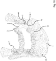
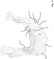
- the guide means 2 a receptacle 9 for the guide member 11 of the head 10 and is connected to the template 1.
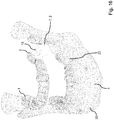
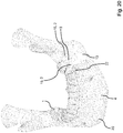
- the template 1 is positively or non-positively locatable on the teeth of the lower jaw 20 shown. Due to the design of the guide means 2, the hollow cutter 3 is guided along the bone 4, so that a bone segment can be removed. It is conceivable that the guide means 2 is formed detachably or non-detachably with the template 1. Furthermore, reference is made to the above description of the figures, which is analogous to the embodiment of the Fig. 9 to 11 applies.
- Fig. 12 to 14 illustrated embodiment corresponds to the in the Fig. 9 to 11 illustrated embodiment, wherein the guide means 2 is additionally formed in addition to the receptacle 9 as a guide sleeve 7.
- the guide sleeve 7 has an angular geometry and is used in particular for the protection of surrounding tissue.
- the guide sleeve 7 may be formed closed at its bottom 21.
- the guide means 2 is formed detachably or non-detachably with the template 1.
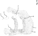
- the embodiment according to 15 to 17 essentially corresponds to the embodiment according to Fig. 3 and 4 , Furthermore, the embodiment corresponds to Fig. 18 to 20 essentially the one in the Fig. 5 and 6 shown device. To avoid repetition, reference is made at this point to the preceding description of the figures, wherein in each case the guide means 2 can be designed to be detachable or non-detachable with the template 1.
- Illustrated stencils 1 can be produced by the method according to the invention.
- a three-dimensional, imaging procedure is first of all carried out in order to obtain three-dimensional data from the jawbone 4 or the withdrawal site 6 and possibly the bone deficit 22.
- a three-dimensional computer model of the jawbone 4 is created.
- the sampling point 6 can be determined, namely taking into account the patient-specific anatomy.
- a patient-specific device can be generated. This can be done, for example, in the rapid prototyping method.
Landscapes
- Health & Medical Sciences (AREA)
- Oral & Maxillofacial Surgery (AREA)
- Life Sciences & Earth Sciences (AREA)
- Dentistry (AREA)
- Veterinary Medicine (AREA)
- General Health & Medical Sciences (AREA)
- Public Health (AREA)
- Animal Behavior & Ethology (AREA)
- Surgery (AREA)
- Epidemiology (AREA)
- Orthopedic Medicine & Surgery (AREA)
- Nuclear Medicine, Radiotherapy & Molecular Imaging (AREA)
- Engineering & Computer Science (AREA)
- Biomedical Technology (AREA)
- Heart & Thoracic Surgery (AREA)
- Medical Informatics (AREA)
- Molecular Biology (AREA)
- Surgical Instruments (AREA)
- Dental Prosthetics (AREA)
Priority Applications (1)
| Application Number | Priority Date | Filing Date | Title |
|---|---|---|---|
| PL18157381T PL3366256T3 (pl) | 2017-02-22 | 2018-02-19 | Urządzenie do prowadzenia chirurgicznego trepana dentystycznego |
Applications Claiming Priority (1)
| Application Number | Priority Date | Filing Date | Title |
|---|---|---|---|
| DE102017202817.3A DE102017202817B3 (de) | 2017-02-22 | 2017-02-22 | Vorrichtung zum Führen einer dentalchirurgischen Hohlfräse |
Publications (3)
| Publication Number | Publication Date |
|---|---|
| EP3366256A2 true EP3366256A2 (fr) | 2018-08-29 |
| EP3366256A3 EP3366256A3 (fr) | 2018-11-07 |
| EP3366256B1 EP3366256B1 (fr) | 2020-05-13 |
Family
ID=60996385
Family Applications (1)
| Application Number | Title | Priority Date | Filing Date |
|---|---|---|---|
| EP18157381.7A Active EP3366256B1 (fr) | 2017-02-22 | 2018-02-19 | Dispositif de guidage d'une fraise creuse de chirurgie dentaire |
Country Status (7)
| Country | Link |
|---|---|
| US (1) | US11007034B2 (fr) |
| EP (1) | EP3366256B1 (fr) |
| DE (1) | DE102017202817B3 (fr) |
| ES (1) | ES2809998T3 (fr) |
| HU (1) | HUE050078T2 (fr) |
| PL (1) | PL3366256T3 (fr) |
| PT (1) | PT3366256T (fr) |
Families Citing this family (7)
| Publication number | Priority date | Publication date | Assignee | Title |
|---|---|---|---|---|
| EP3267923B1 (fr) * | 2015-03-09 | 2020-07-22 | Samrano, Sergio | Ensemble de guidage pour procédures de restauration dentaire |
| US11007035B2 (en) | 2017-03-16 | 2021-05-18 | Viax Dental Technologies Llc | System for preparing teeth for the placement of veneers |
| DE102017115750A1 (de) * | 2017-07-13 | 2019-01-17 | Karl Leibinger Medizintechnik Gmbh & Co. Kg | Knochenpositioniervorrichtung für die Dysgnathie mit Trennwerkzeugführungsvorrichtung / -abschnitt |
| US11432906B2 (en) | 2018-06-18 | 2022-09-06 | Hu-Friedy Mfg. Co., Llc | Dental instrument with a flexible tip end and method of manufacture |
| US11213367B2 (en) * | 2018-12-21 | 2022-01-04 | National Dentex, Llc | Dental bone foundation guide with bur instrument guide features |
| US12138131B2 (en) | 2019-01-04 | 2024-11-12 | Viax Dental Technologies Llc | Tooth preparation system with lateral prongs for limiting three-dimensional movement |
| KR102193710B1 (ko) * | 2019-04-08 | 2020-12-21 | 이태경 | 정밀 맞춤형 멈춤 기능을 갖춘 임플란트 유도수술 기구 시스템 |
Family Cites Families (8)
| Publication number | Priority date | Publication date | Assignee | Title |
|---|---|---|---|---|
| FR2882250B1 (fr) * | 2005-02-24 | 2013-09-27 | Michel Isidori | Dispositifs de guidage et de coupe pour la preparation de sites osseux en chirurgie implantaire |
| JP5467726B2 (ja) * | 2007-09-12 | 2014-04-09 | イマグノーシス株式会社 | インプラント植立用穿孔器具、ハンドピース、ハンドピース用アダプタおよびサージカルガイド |
| DE102008049012A1 (de) * | 2008-09-25 | 2010-04-22 | Bagambisa, Frank, Dr. | Vorrichtung zum Explantieren eines Dentalimplantates aus einem menschlichen oder tierischen Knochen |
| DE102010048090B4 (de) * | 2010-10-01 | 2013-05-16 | Robert Kirmeier | Verfahren zur Herstellung einer Sägeführungsvorrichtung sowie Sägeführungsvorrichtung zur Knochenblockgewinnung |
| DE102012102255B4 (de) * | 2011-03-18 | 2013-07-25 | ICC GmbH implant competence center Öhringen | Behandlungsschablone |
| ITMI20130831A1 (it) * | 2013-05-22 | 2014-11-23 | Stavola Luca De | Metodo di realizzazione di una guida chirurgica per prelievo osseo |
| US9585729B2 (en) * | 2014-12-04 | 2017-03-07 | Hsieh-Hsing Lin | Drill guide device for dental implant |
| DE102015209769A1 (de) * | 2015-05-28 | 2016-12-01 | Frank Zastrow | Chirurgisches Handgerät sowie ein Werkzeug und eine Schutzeinrichtung |
-
2017
- 2017-02-22 DE DE102017202817.3A patent/DE102017202817B3/de not_active Expired - Fee Related
-
2018
- 2018-02-19 ES ES18157381T patent/ES2809998T3/es active Active
- 2018-02-19 PL PL18157381T patent/PL3366256T3/pl unknown
- 2018-02-19 EP EP18157381.7A patent/EP3366256B1/fr active Active
- 2018-02-19 HU HUE18157381A patent/HUE050078T2/hu unknown
- 2018-02-19 PT PT181573817T patent/PT3366256T/pt unknown
- 2018-02-22 US US15/902,553 patent/US11007034B2/en active Active
Also Published As
| Publication number | Publication date |
|---|---|
| HUE050078T2 (hu) | 2020-11-30 |
| DE102017202817B3 (de) | 2018-02-08 |
| PL3366256T3 (pl) | 2020-11-16 |
| US11007034B2 (en) | 2021-05-18 |
| ES2809998T3 (es) | 2021-03-08 |
| PT3366256T (pt) | 2020-08-21 |
| EP3366256A3 (fr) | 2018-11-07 |
| US20180235726A1 (en) | 2018-08-23 |
| EP3366256B1 (fr) | 2020-05-13 |
Similar Documents
| Publication | Publication Date | Title |
|---|---|---|
| DE102017202817B3 (de) | Vorrichtung zum Führen einer dentalchirurgischen Hohlfräse | |
| EP0799605B1 (fr) | Instrument chirurgical dentaire pour la réalisation de cavités dans la mâchoire pour la pose d'implants, ainsi que méthode pour la réalisation de ces cavités | |
| DE602005002951T2 (de) | Massgefertigte implantierbare chirurgische führung und zugehöriges fräswerkzeug und herstellungsverfahren | |
| EP1933757B1 (fr) | Ébauche utilisée comme gabarit de percage et pour enregistrer des enregistrements de données | |
| EP1663051B1 (fr) | Vis de positionnement pour produire une prothese dentaire pour une machoire partiellement ou completement depourvue de dents | |
| DE102012011238B4 (de) | Verfahren zur Herstellung eines Laboranalogs für Dentalimplantate | |
| EP0328911A2 (fr) | Dispositif de perçage pour cavités d'implants chirurgicaux des mâchoires | |
| WO2009000505A1 (fr) | Plaque de fixation et procédé pour son utilisation | |
| DE102016118626A1 (de) | Dentalschablone und Zusammenstellung von Dentalschablonen sowie deren Herstellung | |
| DE3878483T2 (de) | Zahnaerztliche vorrichtung fuer die perforation der kortikalknochen. | |
| EP0681462B1 (fr) | Instruments pour soins dentaires | |
| EP3331470B1 (fr) | Instrument chirurgical | |
| DE102005040739B4 (de) | Bohrschablone | |
| WO2022022787A1 (fr) | Système d'implantation et élément complémentaire destiné à un système d'implantation | |
| DE10036027A1 (de) | Bausatz zur Analyse der Knochenmorphologie im Bereich von Ober- und Unterkiefer zur Vorbereitung für mindestens eine Implantation | |
| EP3294156B1 (fr) | Appareil à main chirurgical et une dispositif de protection | |
| DE4036753A1 (de) | Vorrichtung zur durchfuehrung eines verfahrens zur zahnaerztlichen implantation | |
| EP3212096B1 (fr) | Appareil à main chirurgical, outil et dispositif de protection | |
| DE2834156A1 (de) | Instrumentarium zum herstellen einer nichtrunden alveole | |
| DE10033918A1 (de) | Vorrichtung / Implantat zur geführten Distraktionsosteogenese in atrophierten alveolären Kieferknochen | |
| DE202019105491U1 (de) | Verbessertes Instrument zur Entnahme von Knochenteilen | |
| DE2522941A1 (de) | Oralimplantat | |
| EP1515661B1 (fr) | Instrument chirurgical | |
| DE102015208610A1 (de) | Chirurgisches Werkzeug | |
| DE19902861A1 (de) | Kieferchirurgisches Implantat |
Legal Events
| Date | Code | Title | Description |
|---|---|---|---|
| PUAI | Public reference made under article 153(3) epc to a published international application that has entered the european phase |
Free format text: ORIGINAL CODE: 0009012 |
|
| STAA | Information on the status of an ep patent application or granted ep patent |
Free format text: STATUS: THE APPLICATION HAS BEEN PUBLISHED |
|
| AK | Designated contracting states |
Kind code of ref document: A2 Designated state(s): AL AT BE BG CH CY CZ DE DK EE ES FI FR GB GR HR HU IE IS IT LI LT LU LV MC MK MT NL NO PL PT RO RS SE SI SK SM TR |
|
| AX | Request for extension of the european patent |
Extension state: BA ME |
|
| PUAL | Search report despatched |
Free format text: ORIGINAL CODE: 0009013 |
|
| AK | Designated contracting states |
Kind code of ref document: A3 Designated state(s): AL AT BE BG CH CY CZ DE DK EE ES FI FR GB GR HR HU IE IS IT LI LT LU LV MC MK MT NL NO PL PT RO RS SE SI SK SM TR |
|
| AX | Request for extension of the european patent |
Extension state: BA ME |
|
| RIC1 | Information provided on ipc code assigned before grant |
Ipc: A61C 8/02 20060101ALN20181004BHEP Ipc: A61C 1/08 20060101AFI20181004BHEP Ipc: A61B 17/17 20060101ALI20181004BHEP |
|
| STAA | Information on the status of an ep patent application or granted ep patent |
Free format text: STATUS: REQUEST FOR EXAMINATION WAS MADE |
|
| 17P | Request for examination filed |
Effective date: 20190416 |
|
| RBV | Designated contracting states (corrected) |
Designated state(s): AL AT BE BG CH CY CZ DE DK EE ES FI FR GB GR HR HU IE IS IT LI LT LU LV MC MK MT NL NO PL PT RO RS SE SI SK SM TR |
|
| RIC1 | Information provided on ipc code assigned before grant |
Ipc: A61B 17/17 20060101ALI20191017BHEP Ipc: A61C 1/08 20060101AFI20191017BHEP Ipc: A61C 8/02 20060101ALN20191017BHEP |
|
| GRAP | Despatch of communication of intention to grant a patent |
Free format text: ORIGINAL CODE: EPIDOSNIGR1 |
|
| STAA | Information on the status of an ep patent application or granted ep patent |
Free format text: STATUS: GRANT OF PATENT IS INTENDED |
|
| INTG | Intention to grant announced |
Effective date: 20191204 |
|
| GRAS | Grant fee paid |
Free format text: ORIGINAL CODE: EPIDOSNIGR3 |
|
| GRAA | (expected) grant |
Free format text: ORIGINAL CODE: 0009210 |
|
| STAA | Information on the status of an ep patent application or granted ep patent |
Free format text: STATUS: THE PATENT HAS BEEN GRANTED |
|
| AK | Designated contracting states |
Kind code of ref document: B1 Designated state(s): AL AT BE BG CH CY CZ DE DK EE ES FI FR GB GR HR HU IE IS IT LI LT LU LV MC MK MT NL NO PL PT RO RS SE SI SK SM TR |
|
| REG | Reference to a national code |
Ref country code: GB Ref legal event code: FG4D Free format text: NOT ENGLISH |
|
| REG | Reference to a national code |
Ref country code: CH Ref legal event code: EP |
|
| REG | Reference to a national code |
Ref country code: DE Ref legal event code: R096 Ref document number: 502018001364 Country of ref document: DE |
|
| REG | Reference to a national code |
Ref country code: AT Ref legal event code: REF Ref document number: 1269242 Country of ref document: AT Kind code of ref document: T Effective date: 20200615 |
|
| REG | Reference to a national code |
Ref country code: PT Ref legal event code: SC4A Ref document number: 3366256 Country of ref document: PT Date of ref document: 20200821 Kind code of ref document: T Free format text: AVAILABILITY OF NATIONAL TRANSLATION Effective date: 20200807 |
|
| REG | Reference to a national code |
Ref country code: NL Ref legal event code: FP |
|
| REG | Reference to a national code |
Ref country code: SE Ref legal event code: TRGR |
|
| REG | Reference to a national code |
Ref country code: LT Ref legal event code: MG4D |
|
| REG | Reference to a national code |
Ref country code: GR Ref legal event code: EP Ref document number: 20200402230 Country of ref document: GR Effective date: 20201014 |
|
| PG25 | Lapsed in a contracting state [announced via postgrant information from national office to epo] |
Ref country code: LT Free format text: LAPSE BECAUSE OF FAILURE TO SUBMIT A TRANSLATION OF THE DESCRIPTION OR TO PAY THE FEE WITHIN THE PRESCRIBED TIME-LIMIT Effective date: 20200513 Ref country code: FI Free format text: LAPSE BECAUSE OF FAILURE TO SUBMIT A TRANSLATION OF THE DESCRIPTION OR TO PAY THE FEE WITHIN THE PRESCRIBED TIME-LIMIT Effective date: 20200513 Ref country code: NO Free format text: LAPSE BECAUSE OF FAILURE TO SUBMIT A TRANSLATION OF THE DESCRIPTION OR TO PAY THE FEE WITHIN THE PRESCRIBED TIME-LIMIT Effective date: 20200813 Ref country code: IS Free format text: LAPSE BECAUSE OF FAILURE TO SUBMIT A TRANSLATION OF THE DESCRIPTION OR TO PAY THE FEE WITHIN THE PRESCRIBED TIME-LIMIT Effective date: 20200913 |
|
| PG25 | Lapsed in a contracting state [announced via postgrant information from national office to epo] |
Ref country code: HR Free format text: LAPSE BECAUSE OF FAILURE TO SUBMIT A TRANSLATION OF THE DESCRIPTION OR TO PAY THE FEE WITHIN THE PRESCRIBED TIME-LIMIT Effective date: 20200513 Ref country code: RS Free format text: LAPSE BECAUSE OF FAILURE TO SUBMIT A TRANSLATION OF THE DESCRIPTION OR TO PAY THE FEE WITHIN THE PRESCRIBED TIME-LIMIT Effective date: 20200513 Ref country code: LV Free format text: LAPSE BECAUSE OF FAILURE TO SUBMIT A TRANSLATION OF THE DESCRIPTION OR TO PAY THE FEE WITHIN THE PRESCRIBED TIME-LIMIT Effective date: 20200513 |
|
| REG | Reference to a national code |
Ref country code: HU Ref legal event code: AG4A Ref document number: E050078 Country of ref document: HU |
|
| PG25 | Lapsed in a contracting state [announced via postgrant information from national office to epo] |
Ref country code: AL Free format text: LAPSE BECAUSE OF FAILURE TO SUBMIT A TRANSLATION OF THE DESCRIPTION OR TO PAY THE FEE WITHIN THE PRESCRIBED TIME-LIMIT Effective date: 20200513 |
|
| PG25 | Lapsed in a contracting state [announced via postgrant information from national office to epo] |
Ref country code: DK Free format text: LAPSE BECAUSE OF FAILURE TO SUBMIT A TRANSLATION OF THE DESCRIPTION OR TO PAY THE FEE WITHIN THE PRESCRIBED TIME-LIMIT Effective date: 20200513 Ref country code: SM Free format text: LAPSE BECAUSE OF FAILURE TO SUBMIT A TRANSLATION OF THE DESCRIPTION OR TO PAY THE FEE WITHIN THE PRESCRIBED TIME-LIMIT Effective date: 20200513 Ref country code: EE Free format text: LAPSE BECAUSE OF FAILURE TO SUBMIT A TRANSLATION OF THE DESCRIPTION OR TO PAY THE FEE WITHIN THE PRESCRIBED TIME-LIMIT Effective date: 20200513 |
|
| REG | Reference to a national code |
Ref country code: DE Ref legal event code: R097 Ref document number: 502018001364 Country of ref document: DE |
|
| PG25 | Lapsed in a contracting state [announced via postgrant information from national office to epo] |
Ref country code: SK Free format text: LAPSE BECAUSE OF FAILURE TO SUBMIT A TRANSLATION OF THE DESCRIPTION OR TO PAY THE FEE WITHIN THE PRESCRIBED TIME-LIMIT Effective date: 20200513 |
|
| REG | Reference to a national code |
Ref country code: ES Ref legal event code: FG2A Ref document number: 2809998 Country of ref document: ES Kind code of ref document: T3 Effective date: 20210308 |
|
| PLBE | No opposition filed within time limit |
Free format text: ORIGINAL CODE: 0009261 |
|
| STAA | Information on the status of an ep patent application or granted ep patent |
Free format text: STATUS: NO OPPOSITION FILED WITHIN TIME LIMIT |
|
| 26N | No opposition filed |
Effective date: 20210216 |
|
| PG25 | Lapsed in a contracting state [announced via postgrant information from national office to epo] |
Ref country code: SI Free format text: LAPSE BECAUSE OF FAILURE TO SUBMIT A TRANSLATION OF THE DESCRIPTION OR TO PAY THE FEE WITHIN THE PRESCRIBED TIME-LIMIT Effective date: 20200513 |
|
| P01 | Opt-out of the competence of the unified patent court (upc) registered |
Effective date: 20230515 |
|
| PG25 | Lapsed in a contracting state [announced via postgrant information from national office to epo] |
Ref country code: CY Free format text: LAPSE BECAUSE OF FAILURE TO SUBMIT A TRANSLATION OF THE DESCRIPTION OR TO PAY THE FEE WITHIN THE PRESCRIBED TIME-LIMIT Effective date: 20200513 |
|
| PGFP | Annual fee paid to national office [announced via postgrant information from national office to epo] |
Ref country code: LU Payment date: 20240220 Year of fee payment: 7 |
|
| PGFP | Annual fee paid to national office [announced via postgrant information from national office to epo] |
Ref country code: GR Payment date: 20240219 Year of fee payment: 7 |
|
| PGFP | Annual fee paid to national office [announced via postgrant information from national office to epo] |
Ref country code: IE Payment date: 20240216 Year of fee payment: 7 Ref country code: NL Payment date: 20240220 Year of fee payment: 7 Ref country code: ES Payment date: 20240319 Year of fee payment: 7 |
|
| PGFP | Annual fee paid to national office [announced via postgrant information from national office to epo] |
Ref country code: AT Payment date: 20240216 Year of fee payment: 7 |
|
| PGFP | Annual fee paid to national office [announced via postgrant information from national office to epo] |
Ref country code: MC Payment date: 20240219 Year of fee payment: 7 |
|
| PG25 | Lapsed in a contracting state [announced via postgrant information from national office to epo] |
Ref country code: MK Free format text: LAPSE BECAUSE OF FAILURE TO SUBMIT A TRANSLATION OF THE DESCRIPTION OR TO PAY THE FEE WITHIN THE PRESCRIBED TIME-LIMIT Effective date: 20200513 |
|
| PGFP | Annual fee paid to national office [announced via postgrant information from national office to epo] |
Ref country code: RO Payment date: 20240212 Year of fee payment: 7 Ref country code: HU Payment date: 20240215 Year of fee payment: 7 Ref country code: CZ Payment date: 20240207 Year of fee payment: 7 Ref country code: BG Payment date: 20240216 Year of fee payment: 7 Ref country code: CH Payment date: 20240301 Year of fee payment: 7 Ref country code: GB Payment date: 20240222 Year of fee payment: 7 Ref country code: PT Payment date: 20240219 Year of fee payment: 7 |
|
| PGFP | Annual fee paid to national office [announced via postgrant information from national office to epo] |
Ref country code: TR Payment date: 20240208 Year of fee payment: 7 Ref country code: SE Payment date: 20240221 Year of fee payment: 7 Ref country code: PL Payment date: 20240213 Year of fee payment: 7 Ref country code: IT Payment date: 20240229 Year of fee payment: 7 Ref country code: FR Payment date: 20240222 Year of fee payment: 7 Ref country code: BE Payment date: 20240219 Year of fee payment: 7 |
|
| PGFP | Annual fee paid to national office [announced via postgrant information from national office to epo] |
Ref country code: DE Payment date: 20240429 Year of fee payment: 7 |
|
| PG25 | Lapsed in a contracting state [announced via postgrant information from national office to epo] |
Ref country code: MT Free format text: LAPSE BECAUSE OF FAILURE TO SUBMIT A TRANSLATION OF THE DESCRIPTION OR TO PAY THE FEE WITHIN THE PRESCRIBED TIME-LIMIT Effective date: 20200513 |
|
| REG | Reference to a national code |
Ref country code: DE Ref legal event code: R082 Ref document number: 502018001364 Country of ref document: DE Representative=s name: LICHTI - PATENTANWAELTE PARTNERSCHAFT MBB, DE |
|
| REG | Reference to a national code |
Ref country code: DE Ref legal event code: R119 Ref document number: 502018001364 Country of ref document: DE |
|
| PG25 | Lapsed in a contracting state [announced via postgrant information from national office to epo] |
Ref country code: MC Free format text: LAPSE BECAUSE OF NON-PAYMENT OF DUE FEES Effective date: 20250228 |
|
| REG | Reference to a national code |
Ref country code: SE Ref legal event code: EUG Ref country code: CH Ref legal event code: PL |
|
| REG | Reference to a national code |
Ref country code: NL Ref legal event code: MM Effective date: 20250301 |
|
| PG25 | Lapsed in a contracting state [announced via postgrant information from national office to epo] |
Ref country code: PT Free format text: LAPSE BECAUSE OF NON-PAYMENT OF DUE FEES Effective date: 20250819 |
|
| PG25 | Lapsed in a contracting state [announced via postgrant information from national office to epo] |
Ref country code: GR Free format text: LAPSE BECAUSE OF NON-PAYMENT OF DUE FEES Effective date: 20250903 |
|
| PG25 | Lapsed in a contracting state [announced via postgrant information from national office to epo] |
Ref country code: LU Free format text: LAPSE BECAUSE OF NON-PAYMENT OF DUE FEES Effective date: 20250219 |
|
| REG | Reference to a national code |
Ref country code: AT Ref legal event code: MM01 Ref document number: 1269242 Country of ref document: AT Kind code of ref document: T Effective date: 20250219 |
|
| PG25 | Lapsed in a contracting state [announced via postgrant information from national office to epo] |
Ref country code: BG Free format text: LAPSE BECAUSE OF NON-PAYMENT OF DUE FEES Effective date: 20250219 Ref country code: HU Free format text: LAPSE BECAUSE OF NON-PAYMENT OF DUE FEES Effective date: 20250220 |
|
| PG25 | Lapsed in a contracting state [announced via postgrant information from national office to epo] |
Ref country code: AT Free format text: LAPSE BECAUSE OF NON-PAYMENT OF DUE FEES Effective date: 20250219 |
|
| PG25 | Lapsed in a contracting state [announced via postgrant information from national office to epo] |
Ref country code: CH Free format text: LAPSE BECAUSE OF NON-PAYMENT OF DUE FEES Effective date: 20250228 |
|
| PG25 | Lapsed in a contracting state [announced via postgrant information from national office to epo] |
Ref country code: CZ Free format text: LAPSE BECAUSE OF NON-PAYMENT OF DUE FEES Effective date: 20250219 |
|
| PG25 | Lapsed in a contracting state [announced via postgrant information from national office to epo] |
Ref country code: RO Free format text: LAPSE BECAUSE OF NON-PAYMENT OF DUE FEES Effective date: 20250219 |
|
| GBPC | Gb: european patent ceased through non-payment of renewal fee |
Effective date: 20250219 |
|
| PG25 | Lapsed in a contracting state [announced via postgrant information from national office to epo] |
Ref country code: NL Free format text: LAPSE BECAUSE OF NON-PAYMENT OF DUE FEES Effective date: 20250301 |
|
| REG | Reference to a national code |
Ref country code: BE Ref legal event code: MM Effective date: 20250228 |
|
| PG25 | Lapsed in a contracting state [announced via postgrant information from national office to epo] |
Ref country code: DE Free format text: LAPSE BECAUSE OF NON-PAYMENT OF DUE FEES Effective date: 20250902 |
|
| PG25 | Lapsed in a contracting state [announced via postgrant information from national office to epo] |
Ref country code: GB Free format text: LAPSE BECAUSE OF NON-PAYMENT OF DUE FEES Effective date: 20250219 |
|
| PG25 | Lapsed in a contracting state [announced via postgrant information from national office to epo] |
Ref country code: IT Free format text: LAPSE BECAUSE OF NON-PAYMENT OF DUE FEES Effective date: 20250219 Ref country code: FR Free format text: LAPSE BECAUSE OF NON-PAYMENT OF DUE FEES Effective date: 20250228 |
|
| PG25 | Lapsed in a contracting state [announced via postgrant information from national office to epo] |
Ref country code: BE Free format text: LAPSE BECAUSE OF NON-PAYMENT OF DUE FEES Effective date: 20250228 |
|
| PG25 | Lapsed in a contracting state [announced via postgrant information from national office to epo] |
Ref country code: IE Free format text: LAPSE BECAUSE OF NON-PAYMENT OF DUE FEES Effective date: 20250219 |
|
| REG | Reference to a national code |
Ref country code: ES Ref legal event code: FD2A Effective date: 20260401 |
|
| PG25 | Lapsed in a contracting state [announced via postgrant information from national office to epo] |
Ref country code: ES Free format text: LAPSE BECAUSE OF NON-PAYMENT OF DUE FEES Effective date: 20250220 |