EP3366356A1 - Klappe, insbesondere brandschutzkappe - Google Patents
Klappe, insbesondere brandschutzkappe Download PDFInfo
- Publication number
- EP3366356A1 EP3366356A1 EP17157630.9A EP17157630A EP3366356A1 EP 3366356 A1 EP3366356 A1 EP 3366356A1 EP 17157630 A EP17157630 A EP 17157630A EP 3366356 A1 EP3366356 A1 EP 3366356A1
- Authority
- EP
- European Patent Office
- Prior art keywords
- bearing pin
- damper blade
- bearing
- housing
- flap according
- Prior art date
- Legal status (The legal status is an assumption and is not a legal conclusion. Google has not performed a legal analysis and makes no representation as to the accuracy of the status listed.)
- Granted
Links
Images


Classifications
-
- A—HUMAN NECESSITIES
- A62—LIFE-SAVING; FIRE-FIGHTING
- A62C—FIRE-FIGHTING
- A62C2/00—Fire prevention or containment
- A62C2/06—Physical fire-barriers
- A62C2/12—Hinged dampers
Definitions
- the invention relates to a flap, in particular fire damper, with a, preferably a round or square flow cross-section having, housing and with a pivotally mounted about a pivot axis damper blade with a peripheral edge, wherein the pivot axis forming opposite bearings are provided for supporting the damper blade and wherein at least one bearing point is formed by a recess provided in the housing on the one hand and by a bearing pin on the other hand, and wherein the bearing pin protrudes at least with a partial area in the recess and at least a partial area in a free space of the damper blade.
- the flow cross-section is quadrangular, this may have a rectangular or a square configuration.
- One known in the art fire damper has two opposite bearing pins. At each bearing pin an angle with two holes is provided, by means of which the bearing pin on the damper blade, which consists for example of calcium silicate, can be attached.
- each of the two bearing pins is guided from the inside through the respective recess in the housing. Subsequently, the damper blade is held in the interior of the housing against the two angles, and through the holes in the angles fastening screws are screwed into the damper blade. Both the assembly and disassembly is so costly.
- the object of the invention is to avoid the aforementioned disadvantages and to provide a flap in which the mounting of the bearing pins is simpler.
- the bearing pin is at least one bearing point frictionally held in the free space of the damper blade, the bearing pin is rotatably disposed relative to the damper blade.
- the free space is created by the fact that the bearing pin is moved into the damper blade, for example by pressing, by nailing, by pressing or the like, so that the bearing pin itself generates the finally required free space.
- a free space of smaller diameter already exists, in which the bearing pin of larger diameter, for example, is pressed.
- the bearing pin at least one bearing can also be held only positively in the free space of the damper blade.
- the free space is already there when the bearing pin is guided into the free space.
- the bearing pin is not rotatably disposed relative to the damper blade.
- the bearing pin is at least one bearing friction and positively held in the free space of the damper blade.
- the bearing pin is rotationally fixed relative to the damper blade.
- a displacement of the bearing pin is at least outwardly, preferably only outwardly, and thus prevents a displacement of the bearing pin out of the free space of the damper blade out.
- the bearing pin can be secured at least one bearing by means of at least one, preferably arranged outside the housing, securing element, wherein the securing element displacement of the bearing pin at least outwardly, preferably only outwardly, and thus a displacement of the bearing pin prevented from the free space of the damper blade out.
- securing element prevents such undesired displacement of the bearing pin.
- the inventive design allows for safe storage of the damper blade both a simple installation and a simple subsequent disassembly of the damper blade.
- the relevant bearing pin can be easily and easily brought from the outside into its fixing position. If a disassembly is required later, for example, for the purpose of replacing the damper blade, the bearing pin in question can be easily and easily removed from the outside.
- At least one securing element can be fixed relative to the housing, preferably on the outside of the housing, and act on the end of the bearing pin located in the recess.
- the fuse element - if the fuse element and the housing are made of metal - welded, for example, on the outside of the housing.
- the securing element is designed such that it acts on the end located in the recess of the bearing pin and in this way prevents at least a displacement of the bearing pin to the outside. In this way, a safe storage is ge instantlyrleitstet.
- At least one securing element can be designed as a band, in particular as an adhesive tape, as a Velcro strip, as a rubber band, as a textile band or the like.
- Each bearing pin can be assigned its own securing element, for example a band. If the tape is designed, for example, as an adhesive tape, an adhesive tape of a small dimension in the manner of an adhesive tape segment is sufficient to secure the respective bearing pin. In such a case, it is advisable if the adhesive tape covers the bearing pin and is glued to the surface of the housing arranged immediately around the bearing pin.
- the fuse element secures both bearing pins.
- the securing element is designed, for example, as an adhesive tape, the adhesive tape is at least so long that it covers both bearing pins for a safety device.
- At least one securing element can consist of wire.
- the securing element may be formed, for example, in the manner of a snap ring or a clamping ring. To cover the snap ring or the clamping ring is widened and placed around the housing in the expanded state. In the folded state, the securing element acts on the two ends of the bearing pins. In such a case, the securing element preferably comprises the housing more than 180 ° on the outside. But it is also conceivable that the securing element is designed as a wire, which is wrapped around the housing and the two ends are connected together.
- At least one securing element can completely surround the housing on the outside.
- the two opposite bearing pins can be secured by one and the same securing element.
- the securing element is designed in the manner of a sleeve. If the securing element is, for example, an adhesive tape, if the housing is completely enclosed on the outside, the adhesive tape in this case is at least so long that it is once guided around the housing. Of course, the adhesive tape can also be made longer and thus be guided around the housing more than once. The tape sticks on the outside of the case, so that further fixation is not required.
- At least one bearing pin can have a head end, which protrudes on the outside relative to the housing. The head prevents too wide insertion of the bearing pin in the damper blade.
- the head of at least one bearing pin can be designed as a flat head or as a round head.
- Such a configuration of the bearing pin is only slightly opposite to the outer surface of the housing, so that, for example, an adhesive tape as well as securing element attached can be that the head is covered by the tape.
- a semi-circular head offers itself, inter alia, when using an adhesive tape as a security element, since the half-round head shape, the tape is not damaged.
- At least one bearing pin can be designed as a nail.
- the bearing pin at least one bearing can be an integral part of the damper blade. If, for example, the damper blade consists of a calcium-silicate plate, the corresponding bearing pin consists of calcium silicate.
- the damper blade designed as an integral part bearing pin is inserted in a tilted position of the damper blade from the inside into the corresponding recess in the housing. Subsequently, the damper blade is pivoted so that the pivot axis is aligned orthogonal to the longitudinal extent of the housing. Then the second bearing can be made.
- the bearing pins of the two opposite bearings can be integrally formed.
- the one-piece bearing pin extends through the damper blade and is therefore part of both bearing points.
- the housing can have a subregion extending along the circumference of the valve leaf in the closed state and provided with a material which expands when exposed to heat.
- the subregion can also be bounded on both sides, in particular as a groove.
- the expands upon exposure to heat expands material and seals in the closed position of the damper blade additionally the area between the outer edge, d. H. the edge, the damper blade and the inner surface of the housing.
- the width of the material may preferably correspond at least approximately to the thickness of the damper blade.
- the damper blade can have on the outside on its edge a seal, in particular a seal designed as a cold seal.
- the seal is used in particular for sealing a gap that may remain in the closed position of the damper blade.
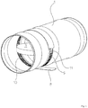
- each flap has a housing 1 with a round flow cross-section and a valve blade 3 mounted pivotably in the housing 1 about a pivot axis 2 with a circumferential edge 4.
- each bearing is formed by a recess 5 provided in the housing 1 on the one hand and by a bearing pin 6 on the other hand, wherein the bearing pin 6 on the one hand at least with a portion in the recess 5 and the other with at least a portion in a free space. 7 the damper blade 3 protrudes.
- the one bearing point is formed by a provided in the housing 1 recess 5 on the one hand and by a bearing pin 6 on the other hand, wherein the bearing pin 6 protrudes on the one hand at least with a portion in the recess 5 and the other with at least a portion of a free space 7 of the damper blade 3
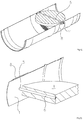
- the other, in Fig. 8 left bearing is formed by a provided in the housing 1 recess 5 on the one hand and by a bearing pin 6 on the other hand, wherein the bearing pin 6 is an integral part of the damper blade 3.
- a securing element 8 which is formed in the illustrated embodiment as an adhesive tape provided.
- the adhesive tape completely surrounds the housing 1 on the outside. The adhesive tape prevents the bearing pins 6 from shifting inadvertently to the outside.
- the housing 1 has, in the portion which extends along the circumference of the valve leaf 3 located in the closed state, five, parallel rows of slot-shaped recesses 9.
- the slot-shaped recesses 9 of a row are separated from each other by webs 10, wherein the webs 10 of adjacent rows are arranged offset from one another.
- This training serves the deterioration of heat transfer in case of fire from the end of the flap facing the fire to the end of the flap facing away from the fire.
- the adhesive tape also prevents the penetration of mortar water into the interior of the housing 1, when the flap is grouted in a breakthrough of a wall.
- the bearing pin 6 ends a head 11, which is formed in the illustrated embodiments as a flat head, on.
- the diameter of the head 11 is greater than the diameter of the recess 5 in the housing 1, so that the head 11 prevents too wide insertion of the bearing pin 6.
- an embodiment with a different head shape, for example, round head possible.
- a semicircular head has seen in section a semicircular configuration.
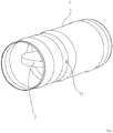
- the 4 to 6 show an embodiment in which the bearing pin 6 is formed as a nail.
- the bearing pin 6 is first guided through the recess 5 in the housing 1 and then driven into the damper blade 3. In this way, the bearing pin 6 generates its free space 7 in the damper blade 3 itself.
- the bearing pin 6 is rotatably fixed in the damper blade 3 in such a configuration.
- the bearing pin 6 of in Fig. 8 left bearing point integral part of the damper blade 3.
- the right bearing point can be formed as in the above-described first or second embodiment.
- a free space 7 - for example, by drilling - has been introduced into the edge 4 of the damper blade 3, in which then the bearing pin 6 is inserted.
- the bearing pin 6 is not rotationally fixed relative to the damper blade 3.
- the securing element 8 the in the present case is designed as an adhesive tape, the bearing pin 6 is secured.
- a displacement of the bearing pin 6 is prevented so far at least outwardly and thus a displacement of the bearing pin 6 from the free space 7 of the damper blade 3 out.
- the continuous bearing pin 6 has a head 11. During assembly, the head opposite the end of the bearing pin 6 is first passed through the recess 5 and then through the continuous space 7 in the opposite recess 5.
- the bearing pin 6 may be rotatably or non-rotatably disposed relative to the damper blade 3.
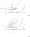
- Fig. 14 an embodiment of a bearing pin 6 is shown, which is held exclusively positively in the free space 7 of the damper blade 3.
- the bearing pin 6 has an arrow-shaped end thickening 12, wherein the corresponding free space 7 has a corresponding contour. Since the inner dimensions of the free space 7 are slightly larger than the outer dimensions of the arrow-like thickening 12, the bearing pin 6 is not rotationally fixed relative to the damper blade 3 is arranged. Due to the positive locking a displacement of the bearing pin 6 relative to the damper blade 3 and thus inadvertent release is prevented.
- Fig. 15 shows an embodiment in which the bearing pin 6 is frictionally and positively held in the free space 7 of the damper blade 3.
- the end of the bearing pin 6, which is located in the free space 7 of the damper blade 3 a thickening 12 with outside grooves 13.
- the grooves 13 are in contact with the inner surface of the clearance 7, so that there is a frictional connection.
- the thickening 12 causes in conjunction with the corresponding configuration of the free space 7 a positive connection.
Landscapes
- Health & Medical Sciences (AREA)
- Public Health (AREA)
- Business, Economics & Management (AREA)
- Emergency Management (AREA)
- Air-Flow Control Members (AREA)
- Building Environments (AREA)
- Special Wing (AREA)
Abstract
Description
- Die Erfindung betrifft eine Klappe, insbesondere Brandschutzklappe, mit einem, vorzugsweise einen runden oder einen viereckigen Strömungsquerschnitt aufweisenden, Gehäuse und mit einem um eine Schwenkachse schwenkbar gelagerten Klappenblatt mit einer umlaufenden Kante, wobei zur Lagerung des Klappenblattes zwei die Schwenkachse bildende gegenüberliegende Lagerstellen vorgesehen sind und wobei zumindest eine Lagerstelle durch eine in dem Gehäuse vorgesehene Ausnehmung einerseits und durch einen Lagerstift andererseits gebildet ist, und wobei der Lagerstift zum einen zumindest mit einem Teilbereich in die Ausnehmung und mit wenigstens einem Teilbereich in einen Freiraum des Klappenblatts hineinragt. Sofern der Strömungsquerschnitt viereckig ausgebildet ist, kann dieser eine rechteckige oder eine quadratische Ausgestaltung aufweisen.
- Eine im Stand der Technik bekannte Brandschutzklappe weist zwei gegenüberliegende Lagerstifte auf. An jedem Lagerstift ist ein Winkel mit zwei Löchern vorgesehen, mittels derer der Lagerstift an dem Klappenblatt, das beispielsweise aus Kalzium-Silikat besteht, befestigt werden kann. Für die Montage des Klappenblattes in der Klappe wird jeder der beiden Lagerstifte von innen durch die betreffende Ausnehmung in dem Gehäuse geführt. Anschließend wird das Klappenblatt im Inneren des Gehäuses gegen die beiden Winkel gehalten, und durch die Löcher in den Winkeln werden Befestigungsschrauben in das Klappenblatt hineingedreht. Sowohl die Montage als auch die Demontage ist insoweit aufwändig.
- Aufgabe der Erfindung ist es, die vorgenannten Nachteile zu vermeiden und eine Klappe anzugeben, bei der die Montage der Lagerstifte einfacher ist.
- Diese Aufgabe wird dadurch gelöst, dass
- der Lagerstift zumindest einer Lagerstelle reibschlüssig und/oder formschlüssig in dem Freiraum des Klappenblattes gehalten ist, so dass eine Verlagerung des Lagerstiftes zumindest nach außen, vorzugsweise ausschließlich nach außen, und damit eine Verlagerung des Lagerstiftes aus dem Freiraum des Klappenblattes heraus verhindert wird,
- der Lagerstift zumindest einer Lagerstelle mittels zumindest eines, vorzugsweise außerhalb des Gehäuses angeordneten, Sicherungselements gesichert ist, wobei das Sicherungselement eine Verlagerung des Lagerstiftes zumindest nach außen, vorzugsweise ausschließlich nach außen, und damit eine Verlagerung des Lagerstiftes aus dem Freiraum des Klappenblattes heraus verhindert.
- Sofern der Lagerstift zumindest einer Lagerstelle reibschlüssig in dem Freiraum des Klappenblattes gehalten ist, ist der Lagerstift drehfest gegenüber dem Klappenblatt angeordnet. Der Freiraum entsteht dadurch, dass der Lagerstift in das Klappenblatt, beispielsweise durch Drücken, durch Nageln, durch Pressen oder dergleichen, bewegt wird, so dass der Lagerstift auf diese Weise den endgültig benötigten Freiraum selbst erzeugt. Selbstverständlich ist es auch möglich, dass ein Freiraum geringeren Durchmessers bereits vorhanden ist, in den der Lagerstift größeren Durchmessers beispielsweise eingepresst wird.
- Der Lagerstift zumindest einer Lagerstelle kann in dem Freiraum des Klappenblattes auch nur formschlüssig gehalten sein. Bei einer solchen Ausgestaltung ist der Freiraum bereits da, wenn der Lagerstift in den Freiraum geführt wird. Bei einer solchen Ausgestaltung ist der Lagerstift nicht drehfest gegenüber dem Klappenblatt angeordnet.
- Selbstverständlich ist es aber auch möglich, dass der Lagerstift zumindest einer Lagerstelle reibschlüssig und formschlüssig in dem Freiraum des Klappenblattes gehalten ist. Bei einer solchen Ausgestaltung ist der Lagerstift drehfest gegenüber dem Klappenblatt.
- Durch die reibschlüssige und/oder formschlüssige Verbindung zwischen dem Lagerstift und dem Klappenblatt wird eine Verlagerung des Lagerstiftes zumindest nach außen, vorzugsweise ausschließlich nach außen, und damit eine Verlagerung des Lagerstiftes aus dem Freiraum des Klappenblattes heraus verhindert.
- Alternativ oder in Ergänzung zu der vorbeschriebenen Ausgestaltung kann der Lagerstift zumindest einer Lagerstelle mittels zumindest eines, vorzugsweise außerhalb des Gehäuses angeordneten, Sicherungselements gesichert sein, wobei das Sicherungselement eine Verlagerung des Lagerstiftes zumindest nach außen, vorzugsweise ausschließlich nach außen, und damit eine Verlagerung des Lagerstiftes aus dem Freiraum des Klappenblattes heraus verhindert. Eine solche Ausgestaltung bietet sich insbesondere dann an, wenn der Lagerstift nicht drehfest gegenüber dem Klappenblatt fixiert ist und sich insoweit nach außen bewegen könnte. Das Sicherungselement verhindert eine solche unerwünschte Verlagerung des Lagerstiftes.
- Sofern es sich um eine Klappe handelt, die beispielsweise in einer unterhalb einer Raumdecke geführten Kanalleitung montiert ist, erlaubt die erfindungsgemäße Ausgestaltung bei einer sicheren Lagerung des Klappenblattes sowohl eine einfache Montage als auch eine einfache spätere Demontage des Klappenblattes. So kann bei der Montage der betreffende Lagerstift einfach und problemlos von außen in seine Fixierposition gebracht werden. Sollte später einmal beispielwiese zum Zwecke des Austausches des Klappenblattes eine Demontage erforderlich sein, kann der betreffende Lagerstift wiederum von außen einfach und problemlos entfernt werden.
- Sofern es sich um eine Brandschutzklappe handelt, ist diese im Bereich ihres Achsbereichs üblicherweise in einen Wand-/Deckendurchbruch eingebaut. Die erfindungsgemäße Ausgestaltung erlaubt bei einer sicheren Lagerung des Klappenblattes wiederum eine einfache Montage vor dem Einbau in den Wand-/Deckendurchbruch. Auch eine spätere Demontage des Klappenblattes ist in der vorbeschriebenen Weise grundsätzlich möglich und aufgrund der erfindungsgemäßen Ausgestaltung auch einfach. Allerdings bedarf es hierzu eines vorherigen Ausbaus der Brandschutzklappe aus dem Wand-/Deckendurchbruch.
- Zumindest ein Sicherungselement kann gegenüber dem Gehäuse, vorzugsweise an der Außenseite des Gehäuses, fixiert sein und auf das in der Ausnehmung befindliche Ende des Lagerstiftes wirken. Bei einer solchen Ausgestaltung ist das Sicherungselement - sofern das Sicherungselement und das Gehäuse aus Metall sind - beispielsweise an dem Gehäuse außenseitig angeschweißt. Das Sicherungselement ist so ausgebildet, dass es auf das in der Ausnehmung befindliche Ende des Lagerstiftes wirkt und auf diese Weise zumindest eine Verlagerung des Lagerstiftes nach außen verhindert. Auf diese Weise ist eine sichere Lagerung gewährleitstet.
- Zumindest ein Sicherungselement kann als Band, insbesondere als Klebeband, als Klettband, als Gummiband, als textiles Band oder dergleichen, ausgebildet sein.
- Jedem Lagerstift kann ein eigenes Sicherungselement, beispielsweise ein Band, zugeordnet sein. Ist das Band beispielsweise als Klebeband ausgebildet, ist ein Klebeband einer geringen Abmessung nach Art eines Klebebandsegmentes ausreichend, um den betreffenden Lagerstift zu sichern. In einem solchen Fall bietet es sich an, wenn das Klebeband den Lagerstift überdeckt und auf die unmittelbar um den Lagerstift herum angeordnete Oberfläche des Gehäuses geklebt ist.
- Es ist aber auch möglich, dass zwei gegenüberliegenden Lagerstiften ein gemeinsames Sicherungselement zugeordnet ist. In diesem Fall sichert das Sicherungselement beide Lagerstifte. Ist das Sicherungselement beispielsweise als Klebeband ausgebildet, ist das Klebeband zumindest so lang, dass es beide Lagerstifte für eine Sicherung überdeckt.
- Zumindest ein Sicherungselement kann aus Draht bestehen. Das Sicherungselement kann beispielsweise nach Art eines Sprengringes bzw. eines Klemmringes ausgebildet sein. Zum Überziehen wird der Sprengring bzw. der Klemmring aufgeweitet und im aufgeweiteten Zustand um das Gehäuse herumgelegt. Im herumgelegten Zustand wirkt das Sicherungselement auf die beiden Enden der Lagerstifte. In einem solchen Fall umfasst das Sicherungselement vorzugsweise das Gehäuse außenseitig mehr als 180°. Es ist aber auch denkbar, dass das Sicherungselement als Draht ausgebildet ist, der um das Gehäuse herumgelegt wird und dessen beiden Enden miteinander verbunden sind.
- Zumindest ein Sicherungselement kann das Gehäuse außenseitig vollständig umfassen. Hierdurch können die beiden gegenüberliegenden Lagerstifte durch ein und dasselbe Sicherungselement gesichert werden. Bei einer solchen Ausgestaltung ist das Sicherungselement nach Art einer Manschette ausgebildet. Handelt es sich bei dem Sicherungselement beispielsweise um ein Klebeband, ist - sofern das Gehäuse außenseitig vollständig umfasst wird - das Klebeband in diesem Fall zumindest so lang, dass es einmal um das Gehäuse herumgeführt ist. Selbstverständlich kann das Klebeband auch länger ausgebildet und damit mehr als einmal um das Gehäuse herumgeführt sein. Das Klebeband klebt dabei auf der Außenseite des Gehäuses, so dass eine weitere Fixierung nicht erforderlich ist.
- Zumindest ein Lagerstift kann endseitig einen Kopf aufweisen, der außenseitig gegenüber dem Gehäuse hervorsteht. Der Kopf verhindert ein zu weites Einführen des Lagerstiftes in das Klappenblatt.
- Dabei kann der Kopf zumindest eines Lagerstiftes als Flachkopf oder als Halbrundkopf ausgebildet sein. Durch eine solche Ausgestaltung steht der Lagerstift nur geringfügig gegenüber der Außenfläche des Gehäuses über, so dass beispielsweise ein Klebeband als Sicherungselement derart gut angebracht werden kann, dass der Kopf durch das Klebeband verdeckt ist. Ein Halbrundkopf bietet sich u. a. bei Verwendung eines Klebebandes als Sicherungselement an, da durch die halbrunde Kopfform das Klebeband nicht beschädigt wird.
- Zumindest ein Lagerstift kann als Nagel ausgebildet sein.
- Der Lagerstift zumindest einer Lagerstelle kann integraler Bestandteil des Klappenblattes sein. Sofern beispielsweise das Klappenblatt aus einer Kalzium-Silikat-Platte besteht, besteht auch der entsprechende Lagerstift aus Kalzium-Silikat. Für die Montage des Klappenblattes wird der als integraler Bestandteil ausgebildete Lagerstift in einer gekippten Stellung des Klappenblattes von innen in die entsprechende Ausnehmung in dem Gehäuse eingeführt. Anschließend wird das Klappenblatt derart verschwenkt, dass die Schwenkachse orthogonal zur Längserstreckung des Gehäuses ausgerichtet ist. Dann kann die zweite Lagerstelle hergestellt werden.
- Die Lagerstifte der beiden gegenüberliegenden Lagerstellen können einteilig ausgebildet sein. Bei einer einteiligen Ausgestaltung erstreckt sich insoweit der einteilig ausgebildete Lagerstift durch das Klappenblatt und ist damit Bestandteil beider Lagerstellen.
- Das Gehäuse kann innenseitig einen sich längs des Umfangs des in geschlossenem Zustand befindlichen Klappenblattes erstreckenden und mit einem sich bei Wärmeeinwirkung ausdehnenden Material versehenen Teilbereich aufweisen. Der Teilbereich kann auch beidseitig begrenzt, insbesondere als Nut ausgebildet, sein. Im Brandfall dehnt sich das bei Wärmeeinwirkung ausdehnende Material aus und dichtet in der Schließstellung des Klappenblattes zusätzlich den Bereich zwischen dem Außenrand, d. h. der Kante, des Klappenblattes und der Innenfläche des Gehäuses ab.
- Die Breite des Materials kann vorzugsweise zumindest in etwa der Dicke des Klappenblattes entsprechen.
- Im geschlossenen Zustand des Klappenblattes kann zwischen dem Außenrand, d. h. der Kante, des Klappenblattes und der Innenfläche des Gehäuses bzw. des Materials, das sich noch nicht durch Wärmeeinwirkung ausgedehnt hat, ein umlaufender Bewegungsspalt vorgesehen sein.
- Das Klappenblatt kann außenseitig auf seiner Kante eine Dichtung, insbesondere eine als Kaltdichtung ausgebildete Dichtung, aufweisen. Die Dichtung dient insbesondere zur Abdichtung eines eventuell in der Schließstellung des Klappenblattes verbleibenden Spalts.
- Im Folgenden werden in den Zeichnungen dargestellte Ausführungsbeispiele der Erfindung erläutert. Es zeigen:
- Fig. 1 - 3
- ein erstes Ausführungsbeispiel einer erfindungsgemäßen Klappe,
- Fig. 4 - 6
- ein zweites Ausführungsbeispiel einer erfindungsgemäßen Klappe,
- Fig. 7 - 10
- ein drittes Ausführungsbeispiel einer erfindungsgemäßen Klappe,
- Fig. 11 - 13
- ein viertes Ausführungsbeispiel einer erfindungsgemäßen Klappe,
- Fig. 14
- einen Schnitt durch ein Klappenblatt im Bereich einer Lagerstelle und
- Fig. 15
- einen Schnitt durch ein Klappenblatt im Bereich einer Lagerstelle.
- In allen Figuren werden für gleiche bzw. gleichartige Bauteile übereinstimmende Bezugszeichen verwendet.
- Die Figuren zeigen eine erfindungsgemäße Klappe unterschiedlicher Ausgestaltungen, wobei die Klappe in den dargestellten Ausführungsbeispielen als Brandschutzklappe ausgebildet ist. Jede Klappe weist ein Gehäuse 1 mit einem runden Strömungsquerschnitt sowie ein in dem Gehäuse 1 um eine Schwenkachse 2 verschwenkbar gelagertes Klappenblatt 3 mit einer umlaufenden Kante 4 auf.
- Zur Lagerung des Klappenblattes 3 sind zwei, die Schwenkachse 2 bildende, gegenüberliegende Lagerstellen vorgesehen. Bei den Ausführungsbeispielen nach den
Fig. 1 bis 3 ,4 bis 6 sowie 11 bis 13 ist jede Lagerstelle durch eine in dem Gehäuse 1 vorgesehene Ausnehmung 5 einerseits und durch einen Lagerstift 6 andererseits gebildet, wobei der Lagerstift 6 zum einen zumindest mit einem Teilbereich in die Ausnehmung 5 und zum anderen mit wenigstens einem Teilbereich in einen Freiraum 7 des Klappenblattes 3 hineinragt. - Bei dem Ausführungsbeispiel nach den
Fig. 7 bis 10 ist die eine Lagerstelle durch eine im Gehäuse 1 vorgesehene Ausnehmung 5 einerseits und durch einen Lagerstift 6 andererseits gebildet, wobei der Lagerstift 6 zum einen zumindest mit einem Teilbereich in die Ausnehmung 5 und zum anderen mit wenigstens einem Teilbereich in einen Freiraum 7 des Klappenblattes 3 hineinragt. Die andere, inFig. 8 linke Lagerstelle ist durch eine im Gehäuse 1 vorgesehene Ausnehmung 5 einerseits und durch einen Lagerstift 6 andererseits gebildet, wobei der Lagerstift 6 integraler Bestandteil des Klappenblattes 3 ist. - Bei den Ausführungsbeispielen nach den
Fig. 1 bis 3 ist der Freiraum 7 in dem Klappenblatt 3 bereits vorhanden, wenn der betreffende Lagerstift 6 von außen durch die Ausnehmung 5 des Gehäuses 1 in den Freiraum 7 des Klappenblattes 3 geführt wird. In Folge dessen ist der Lagerstift 6 nicht drehfest gegenüber dem Klappenblatt 3. Wie denFiguren 1 bis 3 zu entnehmen ist, ist außerhalb des Gehäuses 1 ein Sicherungselement 8, das in dem dargestellten Ausführungsbeispiel als Klebeband ausgebildet ist, vorgesehen. Das Klebeband umfasst das Gehäuse 1 außenseitig vollständig. Das Klebeband verhindert, dass sich die Lagerstifte 6 unbeabsichtigt nach außen verlagern. - Das Gehäuse 1 weist in dem Teilbereich, der sich längs des Umfangs des im geschlossenen Zustand befindlichen Klappenblattes 3 erstreckt, fünf, parallel angeordnete Reihen an schlitzförmigen Ausnehmungen 9 auf. Die schlitzförmigen Ausnehmungen 9 einer Reihe sind durch Stege 10 voneinander getrennt, wobei die Stege 10 benachbarter Reihen versetzt zueinander angeordnet sind. Diese Ausbildung dient der Verschlechterung der Wärmeübertragung im Brandfall von dem, dem Brand zugewandten Ende der Klappe zu dem, dem Brand abgewandten Ende der Klappe. Das Klebeband verhindert auch das Eindringen von Mörtelwasser in das Innere des Gehäuses 1, wenn die Klappe in einem Durchbruch einer Mauer eingemörtelt wird.
- Wie den
Fig. 1 bis 3 zu entnehmen ist, weist der Lagerstift 6 endseitig einen Kopf 11, der in den dargestellten Ausführungsbeispielen als Flachkopf ausgebildet ist, auf. Der Durchmesser des Kopfes 11 ist größer als der Durchmesser der Ausnehmung 5 in dem Gehäuse 1, so dass der Kopf 11 ein zu weites Einführen des Lagerstiftes 6 verhindert. Selbstverständlich ist auch eine Ausgestaltung mit einer anderen Kopfform, beispielsweise Halbrundkopf, möglich. Ein Halbrundkopf hat im Schnitt gesehen eine halbkreisförmige Ausgestaltung. - Die
Fig. 4 bis 6 zeigen ein Ausführungsbeispiel, bei dem der Lagerstift 6 als Nagel ausgebildet ist. Bei der Montage wird der Lagerstift 6 zunächst durch die Ausnehmung 5 in dem Gehäuse 1 geführt und anschließend in das Klappenblatt 3 getrieben. Auf diese Weise erzeugt der Lagerstift 6 seinen Freiraum 7 in dem Klappenblatt 3 selbst. Der Lagerstift 6 ist bei einer solchen Ausgestaltung drehfest in dem Klappenblatt 3 fixiert. - Bei dem dritten Ausführungsbeispiel, das in den
Fig. 7 bis 10 dargestellt ist, ist der Lagerstift 6 der inFig. 8 linken Lagerstelle integraler Bestandteil des Klappenblattes 3. Die rechte Lagerstelle kann wie bei dem vorbeschriebenen ersten oder zweiten Ausführungsbeispiel ausgebildet sein. In dem dargestellten Ausführungsbeispiel ist für die rechte Lagerstelle zunächst ein Freiraum 7 - beispielsweise durch Bohren - in die Kante 4 des Klappenblattes 3 eingebracht worden, in den dann der Lagerstift 6 eingeführt wird. Der Lagerstift 6 ist nicht drehfest gegenüber dem Klappenblatt 3. Durch das Sicherungselement 8, das vorliegend als Klebeband ausgebildet ist, ist der Lagerstift 6 gesichert. Durch das Sicherungselement 8 wird insoweit eine Verlagerung des Lagerstiftes 6 zumindest nach außen und damit eine Verlagerung des Lagerstiftes 6 aus dem Freiraum 7 des Klappenblattes 3 heraus verhindert. - In den
Fig. 11 bis 13 ist ein Ausführungsbeispiel dargestellt, bei dem die Lagerstifte 6 der beiden gegenüberliegenden Lagerstellen einteilig ausgebildet sind. Der durchgehende Lagerstift 6 weist einen Kopf 11 auf. Bei der Montage wird zunächst das dem Kopf gegenüberliegende Ende des Lagerstifts 6 durch die Ausnehmung 5 und dann durch den durchgehenden Freiraum 7 in die gegenüberliegende Ausnehmung 5 geführt. Der Lagerstift 6 kann drehfest oder nicht drehfest gegenüber dem Klappenblatt 3 angeordnet sein. - In
Fig. 14 ist ein Ausführungsbeispiel eines Lagerstiftes 6 dargestellt, der ausschließlich formschlüssig in dem Freiraum 7 des Klappenblattes 3 gehalten ist. Der Lagerstift 6 weist eine pfeilartig ausgebildete endseitige Verdickung 12 auf, wobei der korrespondierende Freiraum 7 eine korrespondierende Kontur aufweist. Da die Innenabmessungen des Freiraums 7 etwas größer als die Außenabmessungen der pfeilartig ausgebildeten Verdickung 12 sind, ist der Lagerstift 6 nicht drehfest gegenüber dem Klappenblatt 3 angeordnet. Durch den Formschluss wird eine Verlagerung des Lagerstiftes 6 gegenüber dem Klappenblatt 3 und damit ein unbeabsichtigtes Lösen verhindert. -
Fig. 15 zeigt ein Ausführungsbeispiel, bei dem der Lagerstift 6 reibschlüssig und formschlüssig in dem Freiraum 7 des Klappenblattes 3 gehalten wird. So weist das Ende des Lagerstiftes 6, das sich in dem Freiraum 7 des Klappenblattes 3 befindet, eine Verdickung 12 mit außenseitigen Rillen 13 auf. Die Rillen 13 sind mit der Innenfläche des Freiraumes 7 in Kontakt, so dass eine reibschlüssige Verbindung besteht. Die Verdickung 12 bewirkt in Verbindung mit der korrespondierenden Ausgestaltung des Freiraums 7 einen Formschluss.
Claims (14)
- Klappe, insbesondere Brandschutzklappe, mit einem, vorzugsweise einen runden oder einen viereckigen Strömungsquerschnitt aufweisenden, Gehäuse (1) und mit einem um eine Schwenkachse (2) schwenkbar gelagerten Klappenblatt (3) mit einer umlaufenden Kante (4), wobei zur Lagerung des Klappenblattes (3) zwei die Schwenkachse (2) bildende gegenüberliegende Lagerstellen vorgesehen sind und wobei zumindest eine Lagerstelle durch eine in dem Gehäuse (1) vorgesehene Ausnehmung (5) einerseits und durch einen Lagerstift (6) andererseits gebildet ist, und wobei der Lagerstift (6) zum einen zumindest mit einem Teilbereich in die Ausnehmung (5) und mit wenigstens einem Teilbereich in einen Freiraum (7) des Klappenblatts (3) hineinragt, dadurch gekennzeichnet, dass
der Lagerstift (6) zumindest einer Lagerstelle reibschlüssig und/oder formschlüssig in dem Freiraum (7) des Klappenblattes (3) gehalten ist
und/oder
der Lagerstift (6) zumindest einer Lagerstelle mittels zumindest eines, vorzugsweise außerhalb des Gehäuses (1) angeordneten, Sicherungselements (8) gesichert ist, wobei das Sicherungselement (8) eine Verlagerung des Lagerstiftes (6) zumindest nach außen, vorzugsweise ausschließlich nach außen, und damit eine Verlagerung des Lagerstiftes (6) aus dem Freiraum (7) des Klappenblattes (3) heraus verhindert. - Klappe nach dem vorhergehenden Anspruch, dadurch gekennzeichnet, dass zumindest ein Sicherungselement (8) gegenüber dem Gehäuse (1), vorzugsweise an der Außenseite des Gehäuses (1), fixiert ist und auf das in der Ausnehmung (5) befindliche Ende des Lagerstiftes (6) wirkt.
- Klappe nach einem der vorhergehenden Ansprüche, dadurch gekennzeichnet, dass zumindest ein Sicherungselement (8) als Band, insbesondere als Klebeband, als Klettband, als Gummiband, als textiles Band oder dergleichen, ausgebildet ist.
- Klappe nach einem der vorhergehenden Ansprüche, dadurch gekennzeichnet, dass zumindest ein Sicherungselement (8) aus Draht besteht.
- Klappe nach einem der vorhergehenden Ansprüche, dadurch gekennzeichnet, dass zumindest ein Sicherungselement (8) das Gehäuse (1) außenseitig vollständig umfasst.
- Klappe nach einem der vorhergehenden Ansprüche, dadurch gekennzeichnet, dass zumindest ein Lagerstift (6) endseitig einen Kopf (11) aufweist, der außenseitig gegenüber dem Gehäuse (1) hervorsteht.
- Klappe nach dem vorhergehenden Anspruch, dadurch gekennzeichnet, dass der Kopf (11) zumindest eines Lagerstiftes (6) als Flachkopf oder als Halbrundkopf ausgebildet ist.
- Klappe nach einem der Ansprüche 6 oder 7, dadurch gekennzeichnet, dass zumindest ein Lagerstift (6) als Nagel ausgebildet ist.
- Klappe nach einem der vorhergehenden Ansprüche, dadurch gekennzeichnet, dass der Lagerstift (6) zumindest einer Lagerstelle integraler Bestandteil des Klappenblattes (3) ist.
- Klappe nach einem der Ansprüche 1 bis 9, dadurch gekennzeichnet, dass die Lagerstifte (6) der beiden gegenüberliegenden Lagerstellen einteilig ausgebildet sind.
- Klappe nach einem der vorhergehenden Ansprüche, dadurch gekennzeichnet, dass das Gehäuse (1) innenseitig einen sich längs des Umfangs des in geschlossenem Zustand befindlichen Klappenblattes (3) erstreckenden und mit einem sich bei Wärmeeinwirkung ausdehnenden Material versehenen Teilbereich aufweist.
- Klappe nach dem vorhergehenden Anspruch, dadurch gekennzeichnet, dass die Breite des Materials vorzugsweise zumindest in etwa der Dicke des Klappenblattes (3) entspricht.
- Klappe nach einem der vorhergehenden Ansprüche, dadurch gekennzeichnet, dass im geschlossenen Zustand des Klappenblattes (3) zwischen dem Außenrand des Klappenblattes (3) und der Innenfläche des Gehäuses (1) bzw. des Materials, das sich noch nicht durch Wärmeeinwirkung ausgedehnt hat, ein umlaufender Bewegungsspalt vorgesehen ist.
- Klappe nach einem der vorhergehenden Ansprüche, dadurch gekennzeichnet, dass das Klappenblatt (3) außenseitig auf seiner Kante (4) eine Dichtung, insbesondere eine als Kaltdichtung ausgebildete Dichtung, aufweist.
Priority Applications (4)
| Application Number | Priority Date | Filing Date | Title |
|---|---|---|---|
| ES17157630T ES2883100T3 (es) | 2017-02-23 | 2017-02-23 | Compuerta, especialmente compuerta cortafuegos |
| EP17157630.9A EP3366356B8 (de) | 2017-02-23 | 2017-02-23 | Klappe, insbesondere brandschutzklappe |
| PL17157630T PL3366356T3 (pl) | 2017-02-23 | 2017-02-23 | Klapa, zwłaszcza klapa przeciwpożarowa |
| DK17157630.9T DK3366356T3 (da) | 2017-02-23 | 2017-02-23 | Klap, især brandbeskyttelsesklap |
Applications Claiming Priority (1)
| Application Number | Priority Date | Filing Date | Title |
|---|---|---|---|
| EP17157630.9A EP3366356B8 (de) | 2017-02-23 | 2017-02-23 | Klappe, insbesondere brandschutzklappe |
Publications (3)
| Publication Number | Publication Date |
|---|---|
| EP3366356A1 true EP3366356A1 (de) | 2018-08-29 |
| EP3366356B1 EP3366356B1 (de) | 2021-05-19 |
| EP3366356B8 EP3366356B8 (de) | 2021-09-01 |
Family
ID=58162479
Family Applications (1)
| Application Number | Title | Priority Date | Filing Date |
|---|---|---|---|
| EP17157630.9A Active EP3366356B8 (de) | 2017-02-23 | 2017-02-23 | Klappe, insbesondere brandschutzklappe |
Country Status (4)
| Country | Link |
|---|---|
| EP (1) | EP3366356B8 (de) |
| DK (1) | DK3366356T3 (de) |
| ES (1) | ES2883100T3 (de) |
| PL (1) | PL3366356T3 (de) |
Citations (6)
| Publication number | Priority date | Publication date | Assignee | Title |
|---|---|---|---|---|
| DE2410561A1 (de) * | 1974-03-06 | 1975-09-11 | Schako Metallwarenfabrik | Feuerschutzklappe fuer lufttechnische anlagen |
| DE2708109A1 (de) * | 1977-02-25 | 1978-08-31 | Schako Metallwarenfabrik | Feuerschutzklappe fuer kanaele von klima- und belueftungsanlagen |
| EP0447944A1 (de) * | 1990-03-17 | 1991-09-25 | Schako Metallwarenfabrik Ferdinand Schad Kg | Brandschutzklappe |
| DE202007013909U1 (de) * | 2007-10-05 | 2008-02-28 | Trox Gmbh | Klappe, insbesondere Brandschutzklappe |
| EP2181733A1 (de) * | 2008-10-28 | 2010-05-05 | MP3 S.r.l. | Feuerbeständige Klappe mit Vertiefungen für einen Stift, die in Kombination aus zwei Rohrelementen erzeugt werden; und Verfahren zur Installation der feuerbeständigen Klappe |
| EP2778554A1 (de) * | 2013-03-11 | 2014-09-17 | TROX GmbH | Absperrklappe für den Einsatz in einer Leitung einer raumlufttechnischen Anlage oder einer maschinellen Entrauchungsanlage |
-
2017
- 2017-02-23 DK DK17157630.9T patent/DK3366356T3/da active
- 2017-02-23 PL PL17157630T patent/PL3366356T3/pl unknown
- 2017-02-23 ES ES17157630T patent/ES2883100T3/es active Active
- 2017-02-23 EP EP17157630.9A patent/EP3366356B8/de active Active
Patent Citations (6)
| Publication number | Priority date | Publication date | Assignee | Title |
|---|---|---|---|---|
| DE2410561A1 (de) * | 1974-03-06 | 1975-09-11 | Schako Metallwarenfabrik | Feuerschutzklappe fuer lufttechnische anlagen |
| DE2708109A1 (de) * | 1977-02-25 | 1978-08-31 | Schako Metallwarenfabrik | Feuerschutzklappe fuer kanaele von klima- und belueftungsanlagen |
| EP0447944A1 (de) * | 1990-03-17 | 1991-09-25 | Schako Metallwarenfabrik Ferdinand Schad Kg | Brandschutzklappe |
| DE202007013909U1 (de) * | 2007-10-05 | 2008-02-28 | Trox Gmbh | Klappe, insbesondere Brandschutzklappe |
| EP2181733A1 (de) * | 2008-10-28 | 2010-05-05 | MP3 S.r.l. | Feuerbeständige Klappe mit Vertiefungen für einen Stift, die in Kombination aus zwei Rohrelementen erzeugt werden; und Verfahren zur Installation der feuerbeständigen Klappe |
| EP2778554A1 (de) * | 2013-03-11 | 2014-09-17 | TROX GmbH | Absperrklappe für den Einsatz in einer Leitung einer raumlufttechnischen Anlage oder einer maschinellen Entrauchungsanlage |
Also Published As
| Publication number | Publication date |
|---|---|
| PL3366356T3 (pl) | 2021-11-22 |
| DK3366356T3 (da) | 2022-01-17 |
| EP3366356B1 (de) | 2021-05-19 |
| ES2883100T3 (es) | 2021-12-07 |
| EP3366356B8 (de) | 2021-09-01 |
Similar Documents
| Publication | Publication Date | Title |
|---|---|---|
| EP2587106B1 (de) | Brandschutzmanschette | |
| CH619282A5 (de) | ||
| DE102007058319B4 (de) | Schneckengewindeschelle | |
| DE19922246B4 (de) | Befestigungsanordnung und Bremsschuhanordnung mit rohrförmigen Nieten | |
| DE60314807T2 (de) | Dichtungsvorrichtung | |
| WO2017220357A1 (de) | Brandschutzelement zum abdichten von durchgangsöffnungen in bauelementen | |
| EP3366356A1 (de) | Klappe, insbesondere brandschutzkappe | |
| DE102004014347B4 (de) | Brandschutzmanschette | |
| DE202008012151U1 (de) | Klappring | |
| EP3290764B1 (de) | Haltevorrichtung für einen länglichen gegenstand | |
| DE102015120509A1 (de) | Schlauchschelle | |
| DE102012217372A1 (de) | Verschlusselement für eine Brandschutzmanschette | |
| DE202005018356U1 (de) | Wand- oder Deckendurchführung | |
| EP0667463B1 (de) | Halteelement aus Kunststoff, insbesondere für Rohrleitungen | |
| DE102011053827B3 (de) | Vorreiberverschluss mit Drehmomentausgleich | |
| EP3623016A1 (de) | Brandschutzklappe mit einem gehäuse für eine darin schwenkbar um eine schwenkachse herum gelagerte absperrklappe und mit einem das gehäuse aussenseitig umgebenen einbausatz | |
| DE102013108275B3 (de) | Scharnier | |
| DE102013210723A1 (de) | Sicherungsmutter | |
| DE3643448C2 (de) | Absperrvorrichtung gegen Brandübertragung in Lüftungsleitungen | |
| DE202009012128U1 (de) | Jalousieklappensystem | |
| DE102017127527B4 (de) | Führungsschiene für ein Linearlager | |
| DE2534297C2 (de) | Feuerschutzklappe | |
| DE102018102261A1 (de) | Spreizdübel | |
| EP3364053B1 (de) | Spreizdübel | |
| DE19503064C1 (de) | Stangenführung |
Legal Events
| Date | Code | Title | Description |
|---|---|---|---|
| PUAI | Public reference made under article 153(3) epc to a published international application that has entered the european phase |
Free format text: ORIGINAL CODE: 0009012 |
|
| STAA | Information on the status of an ep patent application or granted ep patent |
Free format text: STATUS: THE APPLICATION HAS BEEN PUBLISHED |
|
| AK | Designated contracting states |
Kind code of ref document: A1 Designated state(s): AL AT BE BG CH CY CZ DE DK EE ES FI FR GB GR HR HU IE IS IT LI LT LU LV MC MK MT NL NO PL PT RO RS SE SI SK SM TR |
|
| AX | Request for extension of the european patent |
Extension state: BA ME |
|
| STAA | Information on the status of an ep patent application or granted ep patent |
Free format text: STATUS: REQUEST FOR EXAMINATION WAS MADE |
|
| 17P | Request for examination filed |
Effective date: 20190228 |
|
| RBV | Designated contracting states (corrected) |
Designated state(s): AL AT BE BG CH CY CZ DE DK EE ES FI FR GB GR HR HU IE IS IT LI LT LU LV MC MK MT NL NO PL PT RO RS SE SI SK SM TR |
|
| STAA | Information on the status of an ep patent application or granted ep patent |
Free format text: STATUS: EXAMINATION IS IN PROGRESS |
|
| 17Q | First examination report despatched |
Effective date: 20190611 |
|
| GRAP | Despatch of communication of intention to grant a patent |
Free format text: ORIGINAL CODE: EPIDOSNIGR1 |
|
| STAA | Information on the status of an ep patent application or granted ep patent |
Free format text: STATUS: GRANT OF PATENT IS INTENDED |
|
| INTG | Intention to grant announced |
Effective date: 20201204 |
|
| GRAS | Grant fee paid |
Free format text: ORIGINAL CODE: EPIDOSNIGR3 |
|
| GRAA | (expected) grant |
Free format text: ORIGINAL CODE: 0009210 |
|
| STAA | Information on the status of an ep patent application or granted ep patent |
Free format text: STATUS: THE PATENT HAS BEEN GRANTED |
|
| AK | Designated contracting states |
Kind code of ref document: B1 Designated state(s): AL AT BE BG CH CY CZ DE DK EE ES FI FR GB GR HR HU IE IS IT LI LT LU LV MC MK MT NL NO PL PT RO RS SE SI SK SM TR |
|
| REG | Reference to a national code |
Ref country code: GB Ref legal event code: FG4D Free format text: NOT ENGLISH |
|
| REG | Reference to a national code |
Ref country code: CH Ref legal event code: EP |
|
| REG | Reference to a national code |
Ref country code: DE Ref legal event code: R096 Ref document number: 502017010365 Country of ref document: DE |
|
| REG | Reference to a national code |
Ref country code: AT Ref legal event code: REF Ref document number: 1393425 Country of ref document: AT Kind code of ref document: T Effective date: 20210615 |
|
| REG | Reference to a national code |
Ref country code: IE Ref legal event code: FG4D Free format text: LANGUAGE OF EP DOCUMENT: GERMAN |
|
| REG | Reference to a national code |
Ref country code: CH Ref legal event code: PK Free format text: TITEL Ref country code: CH Ref legal event code: PK Free format text: BERICHTIGUNG B8 |
|
| REG | Reference to a national code |
Ref country code: NL Ref legal event code: FP |
|
| REG | Reference to a national code |
Ref country code: SE Ref legal event code: TRGR |
|
| REG | Reference to a national code |
Ref country code: LT Ref legal event code: MG9D |
|
| REG | Reference to a national code |
Ref country code: NO Ref legal event code: T2 Effective date: 20210519 |
|
| PG25 | Lapsed in a contracting state [announced via postgrant information from national office to epo] |
Ref country code: FI Free format text: LAPSE BECAUSE OF FAILURE TO SUBMIT A TRANSLATION OF THE DESCRIPTION OR TO PAY THE FEE WITHIN THE PRESCRIBED TIME-LIMIT Effective date: 20210519 Ref country code: LT Free format text: LAPSE BECAUSE OF FAILURE TO SUBMIT A TRANSLATION OF THE DESCRIPTION OR TO PAY THE FEE WITHIN THE PRESCRIBED TIME-LIMIT Effective date: 20210519 Ref country code: HR Free format text: LAPSE BECAUSE OF FAILURE TO SUBMIT A TRANSLATION OF THE DESCRIPTION OR TO PAY THE FEE WITHIN THE PRESCRIBED TIME-LIMIT Effective date: 20210519 Ref country code: BG Free format text: LAPSE BECAUSE OF FAILURE TO SUBMIT A TRANSLATION OF THE DESCRIPTION OR TO PAY THE FEE WITHIN THE PRESCRIBED TIME-LIMIT Effective date: 20210819 |
|
| PG25 | Lapsed in a contracting state [announced via postgrant information from national office to epo] |
Ref country code: RS Free format text: LAPSE BECAUSE OF FAILURE TO SUBMIT A TRANSLATION OF THE DESCRIPTION OR TO PAY THE FEE WITHIN THE PRESCRIBED TIME-LIMIT Effective date: 20210519 Ref country code: PT Free format text: LAPSE BECAUSE OF FAILURE TO SUBMIT A TRANSLATION OF THE DESCRIPTION OR TO PAY THE FEE WITHIN THE PRESCRIBED TIME-LIMIT Effective date: 20210920 Ref country code: IS Free format text: LAPSE BECAUSE OF FAILURE TO SUBMIT A TRANSLATION OF THE DESCRIPTION OR TO PAY THE FEE WITHIN THE PRESCRIBED TIME-LIMIT Effective date: 20210919 Ref country code: LV Free format text: LAPSE BECAUSE OF FAILURE TO SUBMIT A TRANSLATION OF THE DESCRIPTION OR TO PAY THE FEE WITHIN THE PRESCRIBED TIME-LIMIT Effective date: 20210519 Ref country code: GR Free format text: LAPSE BECAUSE OF FAILURE TO SUBMIT A TRANSLATION OF THE DESCRIPTION OR TO PAY THE FEE WITHIN THE PRESCRIBED TIME-LIMIT Effective date: 20210820 |
|
| REG | Reference to a national code |
Ref country code: ES Ref legal event code: FG2A Ref document number: 2883100 Country of ref document: ES Kind code of ref document: T3 Effective date: 20211207 |
|
| REG | Reference to a national code |
Ref country code: DK Ref legal event code: T3 Effective date: 20220114 |
|
| PG25 | Lapsed in a contracting state [announced via postgrant information from national office to epo] |
Ref country code: SM Free format text: LAPSE BECAUSE OF FAILURE TO SUBMIT A TRANSLATION OF THE DESCRIPTION OR TO PAY THE FEE WITHIN THE PRESCRIBED TIME-LIMIT Effective date: 20210519 Ref country code: SK Free format text: LAPSE BECAUSE OF FAILURE TO SUBMIT A TRANSLATION OF THE DESCRIPTION OR TO PAY THE FEE WITHIN THE PRESCRIBED TIME-LIMIT Effective date: 20210519 Ref country code: CZ Free format text: LAPSE BECAUSE OF FAILURE TO SUBMIT A TRANSLATION OF THE DESCRIPTION OR TO PAY THE FEE WITHIN THE PRESCRIBED TIME-LIMIT Effective date: 20210519 Ref country code: EE Free format text: LAPSE BECAUSE OF FAILURE TO SUBMIT A TRANSLATION OF THE DESCRIPTION OR TO PAY THE FEE WITHIN THE PRESCRIBED TIME-LIMIT Effective date: 20210519 Ref country code: RO Free format text: LAPSE BECAUSE OF FAILURE TO SUBMIT A TRANSLATION OF THE DESCRIPTION OR TO PAY THE FEE WITHIN THE PRESCRIBED TIME-LIMIT Effective date: 20210519 |
|
| REG | Reference to a national code |
Ref country code: DE Ref legal event code: R097 Ref document number: 502017010365 Country of ref document: DE |
|
| PLBE | No opposition filed within time limit |
Free format text: ORIGINAL CODE: 0009261 |
|
| STAA | Information on the status of an ep patent application or granted ep patent |
Free format text: STATUS: NO OPPOSITION FILED WITHIN TIME LIMIT |
|
| 26N | No opposition filed |
Effective date: 20220222 |
|
| PG25 | Lapsed in a contracting state [announced via postgrant information from national office to epo] |
Ref country code: IS Free format text: LAPSE BECAUSE OF FAILURE TO SUBMIT A TRANSLATION OF THE DESCRIPTION OR TO PAY THE FEE WITHIN THE PRESCRIBED TIME-LIMIT Effective date: 20210919 Ref country code: AL Free format text: LAPSE BECAUSE OF FAILURE TO SUBMIT A TRANSLATION OF THE DESCRIPTION OR TO PAY THE FEE WITHIN THE PRESCRIBED TIME-LIMIT Effective date: 20210519 |
|
| PG25 | Lapsed in a contracting state [announced via postgrant information from national office to epo] |
Ref country code: MC Free format text: LAPSE BECAUSE OF FAILURE TO SUBMIT A TRANSLATION OF THE DESCRIPTION OR TO PAY THE FEE WITHIN THE PRESCRIBED TIME-LIMIT Effective date: 20210519 |
|
| PG25 | Lapsed in a contracting state [announced via postgrant information from national office to epo] |
Ref country code: LU Free format text: LAPSE BECAUSE OF NON-PAYMENT OF DUE FEES Effective date: 20220223 |
|
| PG25 | Lapsed in a contracting state [announced via postgrant information from national office to epo] |
Ref country code: IE Free format text: LAPSE BECAUSE OF NON-PAYMENT OF DUE FEES Effective date: 20220223 |
|
| P01 | Opt-out of the competence of the unified patent court (upc) registered |
Effective date: 20230517 |
|
| PG25 | Lapsed in a contracting state [announced via postgrant information from national office to epo] |
Ref country code: HU Free format text: LAPSE BECAUSE OF FAILURE TO SUBMIT A TRANSLATION OF THE DESCRIPTION OR TO PAY THE FEE WITHIN THE PRESCRIBED TIME-LIMIT; INVALID AB INITIO Effective date: 20170223 |
|
| PG25 | Lapsed in a contracting state [announced via postgrant information from national office to epo] |
Ref country code: MK Free format text: LAPSE BECAUSE OF FAILURE TO SUBMIT A TRANSLATION OF THE DESCRIPTION OR TO PAY THE FEE WITHIN THE PRESCRIBED TIME-LIMIT Effective date: 20210519 Ref country code: CY Free format text: LAPSE BECAUSE OF FAILURE TO SUBMIT A TRANSLATION OF THE DESCRIPTION OR TO PAY THE FEE WITHIN THE PRESCRIBED TIME-LIMIT Effective date: 20210519 |
|
| PG25 | Lapsed in a contracting state [announced via postgrant information from national office to epo] |
Ref country code: MT Free format text: LAPSE BECAUSE OF FAILURE TO SUBMIT A TRANSLATION OF THE DESCRIPTION OR TO PAY THE FEE WITHIN THE PRESCRIBED TIME-LIMIT Effective date: 20210519 |
|
| REG | Reference to a national code |
Ref country code: DE Ref legal event code: R081 Ref document number: 502017010365 Country of ref document: DE Owner name: TROX SE, DE Free format text: FORMER OWNER: TROX GMBH, 47506 NEUKIRCHEN-VLUYN, DE |
|
| PGFP | Annual fee paid to national office [announced via postgrant information from national office to epo] |
Ref country code: CH Payment date: 20250301 Year of fee payment: 9 |
|
| PGFP | Annual fee paid to national office [announced via postgrant information from national office to epo] |
Ref country code: PL Payment date: 20251219 Year of fee payment: 10 |
|
| REG | Reference to a national code |
Ref country code: CH Ref legal event code: U11 Free format text: ST27 STATUS EVENT CODE: U-0-0-U10-U11 (AS PROVIDED BY THE NATIONAL OFFICE) Effective date: 20260301 |
|
| PGFP | Annual fee paid to national office [announced via postgrant information from national office to epo] |
Ref country code: NL Payment date: 20260218 Year of fee payment: 10 |
|
| PGFP | Annual fee paid to national office [announced via postgrant information from national office to epo] |
Ref country code: SE Payment date: 20260218 Year of fee payment: 10 |
|
| PGFP | Annual fee paid to national office [announced via postgrant information from national office to epo] |
Ref country code: GB Payment date: 20260219 Year of fee payment: 10 |
|
| PGFP | Annual fee paid to national office [announced via postgrant information from national office to epo] |
Ref country code: ES Payment date: 20260319 Year of fee payment: 10 |
|
| PGFP | Annual fee paid to national office [announced via postgrant information from national office to epo] |
Ref country code: DE Payment date: 20251223 Year of fee payment: 10 Ref country code: DK Payment date: 20260217 Year of fee payment: 10 Ref country code: NO Payment date: 20260217 Year of fee payment: 10 |
|
| PGFP | Annual fee paid to national office [announced via postgrant information from national office to epo] |
Ref country code: AT Payment date: 20260216 Year of fee payment: 10 |
|
| PGFP | Annual fee paid to national office [announced via postgrant information from national office to epo] |
Ref country code: BE Payment date: 20260218 Year of fee payment: 10 Ref country code: IT Payment date: 20260227 Year of fee payment: 10 |
|
| PGFP | Annual fee paid to national office [announced via postgrant information from national office to epo] |
Ref country code: FR Payment date: 20260219 Year of fee payment: 10 |
|
| PGFP | Annual fee paid to national office [announced via postgrant information from national office to epo] |
Ref country code: TR Payment date: 20260213 Year of fee payment: 10 |