EP3366406B1 - Widerstandsschweissen von nichtschweissbaren metallen mit thermisch gespritzten zwischenlagen - Google Patents
Widerstandsschweissen von nichtschweissbaren metallen mit thermisch gespritzten zwischenlagen Download PDFInfo
- Publication number
- EP3366406B1 EP3366406B1 EP17157773.7A EP17157773A EP3366406B1 EP 3366406 B1 EP3366406 B1 EP 3366406B1 EP 17157773 A EP17157773 A EP 17157773A EP 3366406 B1 EP3366406 B1 EP 3366406B1
- Authority
- EP
- European Patent Office
- Prior art keywords
- substrate
- layer
- aluminum
- joining
- thermally sprayed
- Prior art date
- Legal status (The legal status is an assumption and is not a legal conclusion. Google has not performed a legal analysis and makes no representation as to the accuracy of the status listed.)
- Active
Links
Images
Classifications
-
- B—PERFORMING OPERATIONS; TRANSPORTING
- B23—MACHINE TOOLS; METAL-WORKING NOT OTHERWISE PROVIDED FOR
- B23K—SOLDERING OR UNSOLDERING; WELDING; CLADDING OR PLATING BY SOLDERING OR WELDING; CUTTING BY APPLYING HEAT LOCALLY, e.g. FLAME CUTTING; WORKING BY LASER BEAM
- B23K3/00—Tools, devices or special appurtenances for soldering, e.g. brazing, or unsoldering, not specially adapted for particular methods
- B23K3/04—Heating appliances
- B23K3/047—Heating appliances electric
- B23K3/0478—Heating appliances electric comprising means for controlling or selecting the temperature or power
-
- B—PERFORMING OPERATIONS; TRANSPORTING
- B23—MACHINE TOOLS; METAL-WORKING NOT OTHERWISE PROVIDED FOR
- B23K—SOLDERING OR UNSOLDERING; WELDING; CLADDING OR PLATING BY SOLDERING OR WELDING; CUTTING BY APPLYING HEAT LOCALLY, e.g. FLAME CUTTING; WORKING BY LASER BEAM
- B23K11/00—Resistance welding; Severing by resistance heating
- B23K11/06—Resistance welding; Severing by resistance heating using roller electrodes
-
- B—PERFORMING OPERATIONS; TRANSPORTING
- B23—MACHINE TOOLS; METAL-WORKING NOT OTHERWISE PROVIDED FOR
- B23K—SOLDERING OR UNSOLDERING; WELDING; CLADDING OR PLATING BY SOLDERING OR WELDING; CUTTING BY APPLYING HEAT LOCALLY, e.g. FLAME CUTTING; WORKING BY LASER BEAM
- B23K11/00—Resistance welding; Severing by resistance heating
- B23K11/10—Spot welding; Stitch welding
-
- B—PERFORMING OPERATIONS; TRANSPORTING
- B23—MACHINE TOOLS; METAL-WORKING NOT OTHERWISE PROVIDED FOR
- B23K—SOLDERING OR UNSOLDERING; WELDING; CLADDING OR PLATING BY SOLDERING OR WELDING; CUTTING BY APPLYING HEAT LOCALLY, e.g. FLAME CUTTING; WORKING BY LASER BEAM
- B23K11/00—Resistance welding; Severing by resistance heating
- B23K11/10—Spot welding; Stitch welding
- B23K11/11—Spot welding
-
- B—PERFORMING OPERATIONS; TRANSPORTING
- B23—MACHINE TOOLS; METAL-WORKING NOT OTHERWISE PROVIDED FOR
- B23K—SOLDERING OR UNSOLDERING; WELDING; CLADDING OR PLATING BY SOLDERING OR WELDING; CUTTING BY APPLYING HEAT LOCALLY, e.g. FLAME CUTTING; WORKING BY LASER BEAM
- B23K11/00—Resistance welding; Severing by resistance heating
- B23K11/14—Projection welding
-
- B—PERFORMING OPERATIONS; TRANSPORTING
- B23—MACHINE TOOLS; METAL-WORKING NOT OTHERWISE PROVIDED FOR
- B23K—SOLDERING OR UNSOLDERING; WELDING; CLADDING OR PLATING BY SOLDERING OR WELDING; CUTTING BY APPLYING HEAT LOCALLY, e.g. FLAME CUTTING; WORKING BY LASER BEAM
- B23K11/00—Resistance welding; Severing by resistance heating
- B23K11/16—Resistance welding; Severing by resistance heating taking account of the properties of the material to be welded
- B23K11/163—Welding of coated materials
-
- B—PERFORMING OPERATIONS; TRANSPORTING
- B23—MACHINE TOOLS; METAL-WORKING NOT OTHERWISE PROVIDED FOR
- B23K—SOLDERING OR UNSOLDERING; WELDING; CLADDING OR PLATING BY SOLDERING OR WELDING; CUTTING BY APPLYING HEAT LOCALLY, e.g. FLAME CUTTING; WORKING BY LASER BEAM
- B23K11/00—Resistance welding; Severing by resistance heating
- B23K11/16—Resistance welding; Severing by resistance heating taking account of the properties of the material to be welded
- B23K11/20—Resistance welding; Severing by resistance heating taking account of the properties of the material to be welded of different metals
-
- B—PERFORMING OPERATIONS; TRANSPORTING
- B23—MACHINE TOOLS; METAL-WORKING NOT OTHERWISE PROVIDED FOR
- B23K—SOLDERING OR UNSOLDERING; WELDING; CLADDING OR PLATING BY SOLDERING OR WELDING; CUTTING BY APPLYING HEAT LOCALLY, e.g. FLAME CUTTING; WORKING BY LASER BEAM
- B23K26/00—Working by laser beam, e.g. welding, cutting or boring
- B23K26/20—Bonding
- B23K26/32—Bonding taking account of the properties of the material involved
- B23K26/323—Bonding taking account of the properties of the material involved involving parts made of dissimilar metallic material
-
- B—PERFORMING OPERATIONS; TRANSPORTING
- B23—MACHINE TOOLS; METAL-WORKING NOT OTHERWISE PROVIDED FOR
- B23K—SOLDERING OR UNSOLDERING; WELDING; CLADDING OR PLATING BY SOLDERING OR WELDING; CUTTING BY APPLYING HEAT LOCALLY, e.g. FLAME CUTTING; WORKING BY LASER BEAM
- B23K9/00—Arc welding or cutting
- B23K9/23—Arc welding or cutting taking account of the properties of the materials to be welded
- B23K9/232—Arc welding or cutting taking account of the properties of the materials to be welded of different metals
-
- B—PERFORMING OPERATIONS; TRANSPORTING
- B32—LAYERED PRODUCTS
- B32B—LAYERED PRODUCTS, i.e. PRODUCTS BUILT-UP OF STRATA OF FLAT OR NON-FLAT, e.g. CELLULAR OR HONEYCOMB, FORM
- B32B15/00—Layered products comprising a layer of metal
- B32B15/01—Layered products comprising a layer of metal all layers being exclusively metallic
- B32B15/012—Layered products comprising a layer of metal all layers being exclusively metallic one layer being formed of an iron alloy or steel, another layer being formed of aluminium or an aluminium alloy
-
- B—PERFORMING OPERATIONS; TRANSPORTING
- B32—LAYERED PRODUCTS
- B32B—LAYERED PRODUCTS, i.e. PRODUCTS BUILT-UP OF STRATA OF FLAT OR NON-FLAT, e.g. CELLULAR OR HONEYCOMB, FORM
- B32B15/00—Layered products comprising a layer of metal
- B32B15/01—Layered products comprising a layer of metal all layers being exclusively metallic
- B32B15/013—Layered products comprising a layer of metal all layers being exclusively metallic one layer being formed of an iron alloy or steel, another layer being formed of a metal other than iron or aluminium
-
- C—CHEMISTRY; METALLURGY
- C23—COATING METALLIC MATERIAL; COATING MATERIAL WITH METALLIC MATERIAL; CHEMICAL SURFACE TREATMENT; DIFFUSION TREATMENT OF METALLIC MATERIAL; COATING BY VACUUM EVAPORATION, BY SPUTTERING, BY ION IMPLANTATION OR BY CHEMICAL VAPOUR DEPOSITION, IN GENERAL; INHIBITING CORROSION OF METALLIC MATERIAL OR INCRUSTATION IN GENERAL
- C23C—COATING METALLIC MATERIAL; COATING MATERIAL WITH METALLIC MATERIAL; SURFACE TREATMENT OF METALLIC MATERIAL BY DIFFUSION INTO THE SURFACE, BY CHEMICAL CONVERSION OR SUBSTITUTION; COATING BY VACUUM EVAPORATION, BY SPUTTERING, BY ION IMPLANTATION OR BY CHEMICAL VAPOUR DEPOSITION, IN GENERAL
- C23C4/00—Coating by spraying the coating material in the molten state, e.g. by flame, plasma or electric discharge
- C23C4/02—Pretreatment of the material to be coated, e.g. for coating on selected surface areas
-
- C—CHEMISTRY; METALLURGY
- C23—COATING METALLIC MATERIAL; COATING MATERIAL WITH METALLIC MATERIAL; CHEMICAL SURFACE TREATMENT; DIFFUSION TREATMENT OF METALLIC MATERIAL; COATING BY VACUUM EVAPORATION, BY SPUTTERING, BY ION IMPLANTATION OR BY CHEMICAL VAPOUR DEPOSITION, IN GENERAL; INHIBITING CORROSION OF METALLIC MATERIAL OR INCRUSTATION IN GENERAL
- C23C—COATING METALLIC MATERIAL; COATING MATERIAL WITH METALLIC MATERIAL; SURFACE TREATMENT OF METALLIC MATERIAL BY DIFFUSION INTO THE SURFACE, BY CHEMICAL CONVERSION OR SUBSTITUTION; COATING BY VACUUM EVAPORATION, BY SPUTTERING, BY ION IMPLANTATION OR BY CHEMICAL VAPOUR DEPOSITION, IN GENERAL
- C23C4/00—Coating by spraying the coating material in the molten state, e.g. by flame, plasma or electric discharge
- C23C4/04—Coating by spraying the coating material in the molten state, e.g. by flame, plasma or electric discharge characterised by the coating material
- C23C4/06—Metallic material
-
- C—CHEMISTRY; METALLURGY
- C23—COATING METALLIC MATERIAL; COATING MATERIAL WITH METALLIC MATERIAL; CHEMICAL SURFACE TREATMENT; DIFFUSION TREATMENT OF METALLIC MATERIAL; COATING BY VACUUM EVAPORATION, BY SPUTTERING, BY ION IMPLANTATION OR BY CHEMICAL VAPOUR DEPOSITION, IN GENERAL; INHIBITING CORROSION OF METALLIC MATERIAL OR INCRUSTATION IN GENERAL
- C23C—COATING METALLIC MATERIAL; COATING MATERIAL WITH METALLIC MATERIAL; SURFACE TREATMENT OF METALLIC MATERIAL BY DIFFUSION INTO THE SURFACE, BY CHEMICAL CONVERSION OR SUBSTITUTION; COATING BY VACUUM EVAPORATION, BY SPUTTERING, BY ION IMPLANTATION OR BY CHEMICAL VAPOUR DEPOSITION, IN GENERAL
- C23C4/00—Coating by spraying the coating material in the molten state, e.g. by flame, plasma or electric discharge
- C23C4/04—Coating by spraying the coating material in the molten state, e.g. by flame, plasma or electric discharge characterised by the coating material
- C23C4/06—Metallic material
- C23C4/08—Metallic material containing only metal elements
-
- C—CHEMISTRY; METALLURGY
- C23—COATING METALLIC MATERIAL; COATING MATERIAL WITH METALLIC MATERIAL; CHEMICAL SURFACE TREATMENT; DIFFUSION TREATMENT OF METALLIC MATERIAL; COATING BY VACUUM EVAPORATION, BY SPUTTERING, BY ION IMPLANTATION OR BY CHEMICAL VAPOUR DEPOSITION, IN GENERAL; INHIBITING CORROSION OF METALLIC MATERIAL OR INCRUSTATION IN GENERAL
- C23C—COATING METALLIC MATERIAL; COATING MATERIAL WITH METALLIC MATERIAL; SURFACE TREATMENT OF METALLIC MATERIAL BY DIFFUSION INTO THE SURFACE, BY CHEMICAL CONVERSION OR SUBSTITUTION; COATING BY VACUUM EVAPORATION, BY SPUTTERING, BY ION IMPLANTATION OR BY CHEMICAL VAPOUR DEPOSITION, IN GENERAL
- C23C4/00—Coating by spraying the coating material in the molten state, e.g. by flame, plasma or electric discharge
- C23C4/04—Coating by spraying the coating material in the molten state, e.g. by flame, plasma or electric discharge characterised by the coating material
- C23C4/10—Oxides, borides, carbides, nitrides or silicides; Mixtures thereof
-
- C—CHEMISTRY; METALLURGY
- C23—COATING METALLIC MATERIAL; COATING MATERIAL WITH METALLIC MATERIAL; CHEMICAL SURFACE TREATMENT; DIFFUSION TREATMENT OF METALLIC MATERIAL; COATING BY VACUUM EVAPORATION, BY SPUTTERING, BY ION IMPLANTATION OR BY CHEMICAL VAPOUR DEPOSITION, IN GENERAL; INHIBITING CORROSION OF METALLIC MATERIAL OR INCRUSTATION IN GENERAL
- C23C—COATING METALLIC MATERIAL; COATING MATERIAL WITH METALLIC MATERIAL; SURFACE TREATMENT OF METALLIC MATERIAL BY DIFFUSION INTO THE SURFACE, BY CHEMICAL CONVERSION OR SUBSTITUTION; COATING BY VACUUM EVAPORATION, BY SPUTTERING, BY ION IMPLANTATION OR BY CHEMICAL VAPOUR DEPOSITION, IN GENERAL
- C23C4/00—Coating by spraying the coating material in the molten state, e.g. by flame, plasma or electric discharge
- C23C4/18—After-treatment
-
- B—PERFORMING OPERATIONS; TRANSPORTING
- B23—MACHINE TOOLS; METAL-WORKING NOT OTHERWISE PROVIDED FOR
- B23K—SOLDERING OR UNSOLDERING; WELDING; CLADDING OR PLATING BY SOLDERING OR WELDING; CUTTING BY APPLYING HEAT LOCALLY, e.g. FLAME CUTTING; WORKING BY LASER BEAM
- B23K2103/00—Materials to be soldered, welded or cut
- B23K2103/02—Iron or ferrous alloys
- B23K2103/04—Steel or steel alloys
-
- B—PERFORMING OPERATIONS; TRANSPORTING
- B23—MACHINE TOOLS; METAL-WORKING NOT OTHERWISE PROVIDED FOR
- B23K—SOLDERING OR UNSOLDERING; WELDING; CLADDING OR PLATING BY SOLDERING OR WELDING; CUTTING BY APPLYING HEAT LOCALLY, e.g. FLAME CUTTING; WORKING BY LASER BEAM
- B23K2103/00—Materials to be soldered, welded or cut
- B23K2103/18—Dissimilar materials
- B23K2103/20—Ferrous alloys and aluminium or alloys thereof
Definitions
- the present invention relates to make unweldable metal combinations like aluminium to (stainless) steel resistance weldable by applying an aluminum thermal-sprayed layer on the surface of the (stainless) steel with a well-defined thickness, surface roughness and transition resistance (see, for example, JP H04 251676 A ). Then in a second step the resistance (spot) welding process follows.
- the used welding parameters must be selected in a way that only the aluminium to aluminium contact area melts without having brittle intermetallic phases between the aluminium layer and the (stainless) steel.
- the resistance welding is one of the most used welding procedures in metal manufacturing industries.
- the resistance welding can be carried out for instance by spot welding, roller seam welding, Projection welding or weldbonding in order to have welded white goods, fuel tanks, body construction of cars, railways or trucks.
- materials such as hot formed martensitic stainless steels or two and three joint material combinations which do not have weldability for a resistance welding process.
- mechanical solder or brazing depots require deformation and/or cutting of the material in order to have good bond or form closure between the material and the mechanical solder or brazing depots.
- the weld spot has typically as results cold cracks brittle fracture behavior and therefore low strength level as well as a low transmission of power.
- the whole automotive car body engineering industry wants to use different metals like (stainless) steels and aluminium in multi-material design with dissimilar joints.
- state of the art there is no thermal welding method available, only bonding and mechanical joining can be used.
- conventional welding methods brittle intermetallic phases results between aluminum and (stainless) steel.
- spot welding can be used.
- (contact) corrosion resistance can be increased.
- joining forces like similar aluminum joints can be reached for dissimilar combinations.
- the EP patent application 2679328 A1 relates to a method for joining a first joining partner with a second joining partner by means of an electrical resistance welding and a procedural modern permanent connection between the two joining partners.
- Object is to provide an alternate way for joining a first joining partner with a second joining partner using a joining auxiliary and a welding process, in particular to provide a way to add different parts to be joined, in particular, different joining partners, in which at least one comprises an oxide layer.
- a corrosion resistant assembly comprising: a first metal part which is assembled with a second metal component, a joint between the first and the second component, and a corrosion protection layer, at least a portion of the joint covers, wherein the corrosion protective layer of aluminum or zinc.
- the DE patent application 102014011599 relates a method for joining at least two components, wherein in process and production technical simple manner a reliable connection of the two components is possible.
- the weld nugget forms centrally from between the joining auxiliary member and the inside of the second component (steel). This allows the disadvantages of the eccentric material-locking connection, as well as a bad lens formation, inclination of the joining auxiliary element, pore and void formation and isotopically strength properties are reduced.
- the diameter of the dome above material thickening may be smaller than the element head diameter and be dimensioned only so high that a still permissible gap between the two components is obtained.
- the EP patent application 1582283 relates to a process for spot welding two rigid steel sheet parts that are finally primed or painted in an electrophoretic bath comprises arranging small platelets, preferably of easily welded metal such as low-carbon iron, between the sheets at the welding points.
- the DE patent application 10251414 relates to a method for spot welding or soldering by means of resistance or inductive heating of components, in particular sheet metal parts made of metallic materials, as well as a specific method for carrying out the joining auxiliary member.
- a process for spot welding or soldering using resistance or inductive heating comprises determining the heat introduction by a controlled change of the current strength and the joining force depending on a selected cross-sectional contour of a joint auxiliary element inserted between components to be welded or soldered.
- the DE patent applications 102004025493 and 102004025492 relates to a method for joining components, a joining element and a component for joining components.
- Two or more joining parts, particularly metal sheets and / or sheets of plastic by means of joining elements are joined together.
- the components to be joined are provided with openings, in particular provided bores into which the joining elements can be inserted.
- Advantageously can be used as a conventional welding a conventional welding gun, but where is the required heat input due to the soldering significantly lower compared to welding.
- the DE patent application 102012013325 relates to a composite of three or more components easier to manufacture, in particular through a simplified pre-fixing of two or more components to a partial composite prior to final manufacturing of the entire composite component.
- a method for assembling components of different materials An improved composite component of a first component, carried out to enable a second component and a third component, a provision of an auxiliary bonding means, a manufacturing a part composite of one of the two components by means of the joining auxiliary, with: penetration of two of the components by means of the joining aid and producing a positive and / or non-positive connection between the two of the components and the joining tool and a joining of the partial composite penetrating joining auxilia 2 ry to a remaining one of the components by a pressure welding.
- the DE patent application 102012013589 relates to a self-punching fastening element for the resistor element welding for joining more than two formed from flat material components.
- a self-piercing fastening element of the type mentioned which is suitable for the joining of more than two components, wherein at least one of these components may also be formed from a non-plastic deformable material.
- the WO patent application 2010022709 relates to a method of producing a joint connection is thus provided at least between a sheet metal part made of steel, in particular a hot-shaped high-strength steel, and at least one sheet metal component from an aluminum material, in which first a solder deposit by an arc or laser process to ensure safe transportation to one of the metal components is fixed and then disposed between the sheet metal parts on arranged solder deposit and the metal components by applying an electric current and applying the metal components compressive pressure force or be heated by induction heating in the region of a joint such that between the sheet metal part made of steel and the solder deposit a solder and formed between the sheet metal component from aluminum material and the solder deposit a welding or soldering.
- the US patent application 5273204 relates to a method where a butt joint configuration is used to thermal-spray a weld seam into the v-shaped butt joint.
- the thermal sprayed material is at the same time on the weld seam.
- US patent application 20100089977A1 describes a friction stir welding process, where a powder is loosely applied between the two metals to create a special metallurgy and to harden for example an aluminium alloy.
- the idea of the present invention is to make unweldable metal combinations like aluminium to (stainless) steel or general unweldable materials like hot formed martensitic stainless steels resistance weldable by applying an aluminum thermal-sprayed layer on the surface of the (stainless) steel with a well-defined thickness, surface roughness and transition resistance. Then in a second step the resistance (spot) welding process follows.
- the used welding parameters must be selected in a way that only the aluminium to aluminium contact area melts without having brittle intermetallic phases between the aluminium layer and the (stainless) steel.
- the formula for the phase growth can be formulated with parabolic growth
- the parabolic growth curve formula provides information on the layer thickness for typical spot welds, which means a strength decrease of more than 50% in comparison to the aluminum base material.
- Layer thickness typical for spot welds is greater than or equal to 15 ⁇ m. That means a strength decrease of more than 50% in comparison to aluminium base material (280N/mm 2 ). As a result of this the invention must avoid any growth of an intermetallic phase during welding.
- thermomechanical coating method regarding to this invention can consist of flame spaying, arc spraying, plasma spraying, laser spraying, cold gas spraying, detonation spraying, high velocity oxygen fuel spraying or molten pool spraying.
- the materials, non-weldable directly together without the thermal sprayed layer to be used by the method of the present invention are for instance steels like unalloyed, low-alloyed or stainless steels, aluminium, an aluminum based alloy, magnesium or a magnesium based alloy.
- the thermal sprayed layer is welded according to this invention with resistance spot welding.
- the ratio of the thermal sprayed layer thickness to the reached by spot weld diameter is under/lower or equal to 0.25 mm.
- the total sheet thickness including substrate, thermal sprayed layer, applied sheet is between 1.5 mm up to 6.0 mm, while the transition zone between thermal sprayed layer and the base material is under 350 °C.
- T is the total sheet thickness [mm] summing up of t base + t sprayed layer + t applied sheet t base is the sheet thickness [mm] of the base material, in the upper example of (stainless) steel.
- t sprayed layer is the thickness [mm] of the thermal sprayed layer, in the upper examples manufactured with an arc spraying process where a wire of AlMg 3 was used.
- At least t applied sheet is the thickness [mm] of the sheet, which is applied onto the thermomechanical coated layer, which was in the upper examples of an aluminum sheet of an EN AW-6081 alloy.
- the substrate to be thermal sprayed can consists of a steel material, unalloyed or low-alloyed steel with a hot-dip and electrolytically galvanized surface coating. More preferably it is a stainless steel with a chromium-oxid passivation layer. Additionally the materials to be used suitable in the method of the present invention can be also hot-formed or press-hardened steels with a scaled surface or a surface protection layer with aluminum-silicon or zinc layer coating.
- the substrate to be thermal sprayed can be an unalloyed or low-alloyed steel having the carbon equivalent (CEV) more than 0,65 %, where CEV is calculated using a formula (element contents by weight %)
- CEV C + Mn/6 + (Cu + Ni)/15 + (Cr + Mo + V)/5.
- the substrate surface can be treated in accordance with the present invention pretreated by cleaning or degreasing, and blasting or peening.
- the blasting abrasive for blasting or peening can consists also of corundum, steel wire, silicium carbide, and hard cast gravel or glass bead.
- the present invention shows a high power transmission of those dissimilar welds.
- the fracture behavior can be concentrated into the applied sheet area. Therefore it is possible with the invention to reach a higher or equal power transmission in relation to a similar weld of one of the materials in state of the art, compared to the same thickness combination.
- One kind of example is to create an aluminium thermal sprayed layer on to the top of stainless steel surface, which uses the effect of diffusion, adhesion, mechanical interlocking of the layer, chemical binding and where the layer on stainless steel is consisting of an aluminium-based alloy and which combination is welded by a resistance welding with an applied aluminum sheet to avoid intermetallic brittle phases.
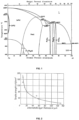
- Fig. 1 illustrates a theoretical background for a binary system, which only works for infinitely long cooling rates and as a result of that the resistance spot welding has ⁇ 1,500K/s cooling rate with brittle intermetallic phases: FeAl 3 and Fe 2 Al 5 .
- a binary system* of Fe/AI is represented with a temperature range. *The source is from Guimaraens, E., university of Bayreuth, 2005.
- Fig. 2 illustrates a theoretical background for a phase growth, which is formulated with parabolic growth curve.
- the relation of intermetallic layer thickness and tensile strength is presented.
- a layer thickness for typical spot welds is more than or equal to 15 ⁇ m.
- the curve shows a strength decrease of more than 50% in comparison to aluminium base material (280N/mm 2 ). Because of that phenomenon in the present invention a method regarding to this any growth of an intermetallic phase during welding must avoid.
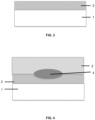
- thermomechanical or mechanical Al-alloyed surface coating manufactured with a thermal sprayed interlayer (2) is on the top of substrate material (1) like stainless steel, which is non-weldable directly to each other.
- Fig. 4 illustrates a schematic view of the preferred embodiment of the invention from the side view, where resistance spot welding process between thermal sprayed coating layer (2) on substrate (1) and an applied aluminium (3) sheet is used to join the material combination.
- the temperature in the contact area between the substrate (1) and the thermal sprayed coating layer is, according to the present invention, under 350 Celsius degree.
Landscapes
- Engineering & Computer Science (AREA)
- Chemical & Material Sciences (AREA)
- Mechanical Engineering (AREA)
- Physics & Mathematics (AREA)
- Plasma & Fusion (AREA)
- Materials Engineering (AREA)
- Chemical Kinetics & Catalysis (AREA)
- Metallurgy (AREA)
- Organic Chemistry (AREA)
- Optics & Photonics (AREA)
- Coating By Spraying Or Casting (AREA)
- Arc Welding In General (AREA)
- Resistance Welding (AREA)
Claims (7)
- Verfahren zum Verbinden von mindestens zwei nicht direkt miteinander verschweißbaren Materialien durch thermische Fügeverfahren in einer Überlappungskonfiguration, wobei eine zweistufige Sequenz verwendet wird, die aus einem ersten Schritt zum Aufbringen einer Oberflächenschutzschicht durch thermisches Spritzen auf die Oberfläche eines Stahlsubstrats, wie z.B. eines unlegierten, eines niedriglegierten oder eines rostfreien Stahls (1), und einem zweiten Schritt besteht, bei dem ein Punktschweißverfahren verwendet wird, um die Schutzschicht (2) an ein aufgebrachtes Aluminium-, Aluminiumbasislegierungs-, Magnesium- oder Magnesiumbasislegierungsblech (3) zu schweißen, ohne dass spröde intermetallische Phasen in der gesamten Materialkonfiguration auftreten, und wobei die Temperatur im Kontaktbereich zwischen dem Substrat (1) und der thermisch aufgespritzten Überzugsschicht unter 350 °C liegt, dadurch gekennzeichnet, dass die thermisch gespritzte Schicht (2) aus Aluminium, einer Legierung auf Aluminiumbasis oder einer Kombination aus Aluminium und Karbiden besteht und eine Dicke zwischen 0,25 mm und 1,5 mm aufweist.
- Verfahren nach Anspruch 1, dadurch gekennzeichnet, dass die Oberflächenschutzschicht durch ein thermomechanisches Beschichtungsverfahren ausgeführt wird.
- Verfahren nach einem der vorhergehenden Ansprüche, dadurch gekennzeichnet, dass die Gesamtblechdicke, einschließlich des Substrats (1), der thermisch gespritzten Schicht (2) und des aufgebrachten Blechs (3), zwischen 1,5 mm und 6,0 mm beträgt.
- Verfahren nach einem der vorhergehenden Ansprüche, dadurch gekennzeichnet, dass das thermisch zu bespritzende Substrat (1) ein Kohlenstoffstahl mit einem Kohlenstoffäquivalent (CEV) von mehr als 0,65 % ist, wobei CEV nach der Formel (Elementgehalt in Gewichtsprozent) CEV = C + Mn/6 + (Cu + Ni)/15 + (Cr + Mo + V)/5 berechnet wird.
- Verfahren nach einem der vorhergehenden Ansprüche, dadurch gekennzeichnet, dass das thermisch zu bespritzende Substrat (1) ein Kohlenstoffstahlmaterial ist, vorzugsweise Kohlenstoffstahl mit einer verzinkten Oberflächenbeschichtung.
- Verfahren nach einem der Ansprüche 1 - 5, dadurch gekennzeichnet, dass das thermisch zu bespritzende Substrat (1) ein rostfreier Stahl ist.
- Verfahren nach einem der vorhergehenden Ansprüche, dadurch gekennzeichnet, dass die Oberfläche des Substrats (1) durch Reinigen und Strahlen vorbehandelt wird.
Priority Applications (22)
| Application Number | Priority Date | Filing Date | Title |
|---|---|---|---|
| EP17157773.7A EP3366406B1 (de) | 2017-02-24 | 2017-02-24 | Widerstandsschweissen von nichtschweissbaren metallen mit thermisch gespritzten zwischenlagen |
| EP17209825.3A EP3369516B1 (de) | 2017-02-24 | 2017-02-24 | Mehrstufiges fügeverfahren mit thermisch gespritzten schichten |
| CA3053613A CA3053613A1 (en) | 2017-02-24 | 2018-02-16 | Resistance welding of unweldable metals with thermal sprayed interlayers |
| SG10202108993YA SG10202108993YA (en) | 2017-02-24 | 2018-02-16 | Resistance welding of unweldable metals with thermal sprayed interlayers |
| CN201880012634.5A CN110312589B (zh) | 2017-02-24 | 2018-02-16 | 以热机械涂布的中间层电阻焊接不可焊金属的方法 |
| AU2018223090A AU2018223090A1 (en) | 2017-02-24 | 2018-02-16 | Resistance welding of unweldable metals with thermal sprayed interlayers |
| SG11201907514XA SG11201907514XA (en) | 2017-02-24 | 2018-02-16 | Resistance welding of unweldable metals with thermal sprayed interlayers |
| BR112019017427-3A BR112019017427B1 (pt) | 2017-02-24 | 2018-02-16 | Método para união de pelo menos dois materiais |
| KR1020197026381A KR102436341B1 (ko) | 2017-02-24 | 2018-02-16 | 용사 중간층들을 갖는 용접 불가능한 금속들의 저항 용접 |
| PCT/EP2018/053892 WO2018153785A1 (en) | 2017-02-24 | 2018-02-16 | Resistance welding of unweldable metals with thermal sprayed interlayers |
| US16/487,930 US11548087B2 (en) | 2017-02-24 | 2018-02-16 | Resistance welding of unweldable metals with thermal sprayed interlayers |
| JP2019546234A JP7261167B2 (ja) | 2017-02-24 | 2018-02-16 | 溶射された中間層を用いた溶接できない金属の抵抗溶接 |
| MYPI2019004827A MY205920A (en) | 2017-02-24 | 2018-02-16 | Resistant welding of unweldable metals with thermal sprayed interlayers |
| MX2019010071A MX2019010071A (es) | 2017-02-24 | 2018-02-16 | Soldadura por resistencia de metales no soldables con capas intercaladas pulverizadas termicamente. |
| RU2019126649A RU2776711C2 (ru) | 2017-02-24 | 2018-02-16 | Контактная сварка несвариваемых металлов с помощью нанесенных термическим напылением промежуточных слоев |
| TW107106193A TWI762588B (zh) | 2017-02-24 | 2018-02-23 | 以熱噴塗中間層電阻焊接不可焊金屬 |
| TW107145270A TWI783095B (zh) | 2017-02-24 | 2018-12-14 | 使用熱噴覆層之多階段接合方法 |
| US16/955,865 US11524351B2 (en) | 2017-02-24 | 2018-12-19 | Multistage joining process with thermal sprayed layers |
| PCT/EP2018/000565 WO2019149336A1 (en) | 2017-02-24 | 2018-12-19 | Multistage joining process with thermal sprayed layers |
| CN201880077294.4A CN111432971A (zh) | 2017-02-24 | 2018-12-19 | 利用热喷涂层的多级接合工艺 |
| ZA2019/05415A ZA201905415B (en) | 2017-02-24 | 2019-08-15 | Resistance welding of unweldable metals with thermal sprayed interlayers |
| AU2024201319A AU2024201319B2 (en) | 2017-02-24 | 2024-02-28 | Resistance welding of unweldable metals with thermal sprayed interlayers |
Applications Claiming Priority (1)
| Application Number | Priority Date | Filing Date | Title |
|---|---|---|---|
| EP17157773.7A EP3366406B1 (de) | 2017-02-24 | 2017-02-24 | Widerstandsschweissen von nichtschweissbaren metallen mit thermisch gespritzten zwischenlagen |
Related Child Applications (2)
| Application Number | Title | Priority Date | Filing Date |
|---|---|---|---|
| EP17209825.3A Division-Into EP3369516B1 (de) | 2017-02-24 | 2017-02-24 | Mehrstufiges fügeverfahren mit thermisch gespritzten schichten |
| EP17209825.3A Division EP3369516B1 (de) | 2017-02-24 | 2017-02-24 | Mehrstufiges fügeverfahren mit thermisch gespritzten schichten |
Publications (2)
| Publication Number | Publication Date |
|---|---|
| EP3366406A1 EP3366406A1 (de) | 2018-08-29 |
| EP3366406B1 true EP3366406B1 (de) | 2024-12-25 |
Family
ID=58158959
Family Applications (2)
| Application Number | Title | Priority Date | Filing Date |
|---|---|---|---|
| EP17157773.7A Active EP3366406B1 (de) | 2017-02-24 | 2017-02-24 | Widerstandsschweissen von nichtschweissbaren metallen mit thermisch gespritzten zwischenlagen |
| EP17209825.3A Active EP3369516B1 (de) | 2017-02-24 | 2017-02-24 | Mehrstufiges fügeverfahren mit thermisch gespritzten schichten |
Family Applications After (1)
| Application Number | Title | Priority Date | Filing Date |
|---|---|---|---|
| EP17209825.3A Active EP3369516B1 (de) | 2017-02-24 | 2017-02-24 | Mehrstufiges fügeverfahren mit thermisch gespritzten schichten |
Country Status (13)
| Country | Link |
|---|---|
| US (2) | US11548087B2 (de) |
| EP (2) | EP3366406B1 (de) |
| JP (1) | JP7261167B2 (de) |
| KR (1) | KR102436341B1 (de) |
| CN (2) | CN110312589B (de) |
| AU (1) | AU2018223090A1 (de) |
| CA (1) | CA3053613A1 (de) |
| MX (1) | MX2019010071A (de) |
| MY (1) | MY205920A (de) |
| SG (2) | SG11201907514XA (de) |
| TW (2) | TWI762588B (de) |
| WO (2) | WO2018153785A1 (de) |
| ZA (1) | ZA201905415B (de) |
Families Citing this family (6)
| Publication number | Priority date | Publication date | Assignee | Title |
|---|---|---|---|---|
| US11524358B2 (en) * | 2018-11-07 | 2022-12-13 | GM Global Technology Operations LLC | Mechanical performance of al-steel weld joints |
| CN114340833B (zh) * | 2019-08-27 | 2024-03-19 | 株式会社神户制钢所 | 异种材料接合结构体的制造方法和异种材料接合结构体 |
| DE102021106365A1 (de) | 2021-03-16 | 2022-09-22 | Bayerische Motoren Werke Aktiengesellschaft | Verfahren zum Fügen von Bauteilen sowie Bauteilverbindung |
| CN115354264B (zh) * | 2021-05-02 | 2024-01-30 | 兰州交通大学 | 一种304不锈钢板表面喷涂铝金属的喷涂方法 |
| CN115255585B (zh) * | 2022-07-21 | 2023-10-20 | 吉林大学 | 一种基于电弧喷涂中间层的铝镁异种合金电阻点焊方法 |
| KR102906221B1 (ko) * | 2023-07-14 | 2026-01-02 | (주)티티에스 | 스테인리스 스틸과 하스텔로이의 이종 접합 용접 방법 |
Citations (1)
| Publication number | Priority date | Publication date | Assignee | Title |
|---|---|---|---|---|
| CN101643899A (zh) * | 2009-09-05 | 2010-02-10 | 中国船舶重工集团公司第七二五研究所 | 一种异种金属焊接中间层的制备方法 |
Family Cites Families (25)
| Publication number | Priority date | Publication date | Assignee | Title |
|---|---|---|---|---|
| US5273204A (en) | 1988-03-25 | 1993-12-28 | Howmet Corporation | Method for joining materials by metal spraying |
| JPH04251676A (ja) * | 1991-01-28 | 1992-09-08 | Nisshin Steel Co Ltd | 鋼材とアルミニウム系材料との抵抗溶接方法 |
| JPH067952A (ja) * | 1992-05-28 | 1994-01-18 | Nippon Steel Corp | 複層鋼板の溶接方法 |
| JPH0724581A (ja) * | 1993-02-03 | 1995-01-27 | Sumitomo Metal Ind Ltd | アルミニウムと鋼の抵抗溶接方法 |
| WO2000038854A1 (en) * | 1998-12-28 | 2000-07-06 | Abb Alstom Power Inc. | Method of fabricating fins on heat exchanger tubes |
| JP2001087866A (ja) * | 1999-09-24 | 2001-04-03 | Denso Corp | アルミニウムと銅との接合方法 |
| JP2004090093A (ja) * | 2002-08-15 | 2004-03-25 | Yoshimitsu Miyaki | 異種金属接合用インサート材 |
| DE10251414B4 (de) | 2002-11-01 | 2012-08-16 | Volkswagen Ag | Verfahren und Fügehilfselement zum Punktschweißen oder -löten |
| DE102004016512A1 (de) | 2004-04-03 | 2005-10-20 | Bayerische Motoren Werke Ag | Verfahren zum Punktschweißen von zwei Blechteilen |
| DE102004025493A1 (de) | 2004-05-21 | 2005-12-15 | Volkswagen Ag | Verfahren zum Fügen mittels Löten, sowie Fügeelement und Bauteil nach dem Verfahren |
| DE102004025492A1 (de) | 2004-05-21 | 2009-08-06 | Volkswagen Ag | Verfahren zum Fügen mittels mechanischen Eintreibens und Verschweißens eines Fügeelementes, sowie derartiges Fügeelement |
| JP4601052B2 (ja) * | 2004-12-24 | 2010-12-22 | 日産自動車株式会社 | 異種金属の接合方法 |
| CN101259563A (zh) * | 2008-04-11 | 2008-09-10 | 哈尔滨工业大学 | 铝钢异种金属预涂层连接方法 |
| DE102008044691A1 (de) | 2008-08-28 | 2010-03-04 | Volkswagen Ag | Verfahren zur Herstellung einer Fügeverbindung |
| US7997472B2 (en) * | 2008-10-14 | 2011-08-16 | GM Global Technology Operations LLC | Friction stir welding using an adhesive, copper, tin and zinc interlayer |
| US20100089977A1 (en) | 2008-10-14 | 2010-04-15 | Gm Global Technology Operations, Inc. | Friction stir welding of dissimilar metals |
| US8963042B2 (en) * | 2009-04-09 | 2015-02-24 | GM Global Technology Operations LLC | Welding light metal workpieces by reaction metallurgy |
| DE102012013014A1 (de) | 2012-06-29 | 2014-01-02 | Slv Halle Gmbh | Fügen von zwei Fügepartnern mittels einer Kombination eines elektrischen Widerstandsschweißens und eines Reibschweißens |
| DE102012013325A1 (de) | 2012-07-06 | 2014-10-30 | Volkswagen Aktiengesellschaft | Fügen von Bauelementen aus unterschiedlichen Werkstoffen mittels eines Fügehilfsmittels |
| DE102012013589A1 (de) | 2012-07-10 | 2014-01-16 | Volkswagen Aktiengesellschaft | Selbststanzendes Fügeelement für das Widerstandselementschweißen und Bauteilverbund mit wenigstens einem solchen Fügeelement |
| CH708666A1 (de) * | 2013-10-08 | 2015-04-15 | Kistler Holding Ag | Verfahren zur Herstellung einer Metall-Keramiklötverbindung. |
| JP6246666B2 (ja) * | 2014-06-11 | 2017-12-13 | 日本発條株式会社 | 積層体の製造方法 |
| DE102014011599A1 (de) | 2014-08-02 | 2016-02-04 | Audi Ag | Verfahren zum Fügen zumindest zweier Bauteile |
| PL3067147T3 (pl) * | 2015-03-13 | 2020-09-21 | Outokumpu Oyj | Sposób zgrzewania przy użyciu przekładki, materiałów na bazie metalu nie ulegających zgrzewaniu ze sobą bezpośrednio |
| US20160319417A1 (en) | 2015-04-28 | 2016-11-03 | Ford Global Technologies, Llc | Thermal Spray for Corrosion Protection |
-
2017
- 2017-02-24 EP EP17157773.7A patent/EP3366406B1/de active Active
- 2017-02-24 EP EP17209825.3A patent/EP3369516B1/de active Active
-
2018
- 2018-02-16 MX MX2019010071A patent/MX2019010071A/es unknown
- 2018-02-16 MY MYPI2019004827A patent/MY205920A/en unknown
- 2018-02-16 KR KR1020197026381A patent/KR102436341B1/ko active Active
- 2018-02-16 SG SG11201907514XA patent/SG11201907514XA/en unknown
- 2018-02-16 CN CN201880012634.5A patent/CN110312589B/zh active Active
- 2018-02-16 CA CA3053613A patent/CA3053613A1/en active Pending
- 2018-02-16 AU AU2018223090A patent/AU2018223090A1/en not_active Abandoned
- 2018-02-16 SG SG10202108993YA patent/SG10202108993YA/en unknown
- 2018-02-16 JP JP2019546234A patent/JP7261167B2/ja active Active
- 2018-02-16 WO PCT/EP2018/053892 patent/WO2018153785A1/en not_active Ceased
- 2018-02-16 US US16/487,930 patent/US11548087B2/en active Active
- 2018-02-23 TW TW107106193A patent/TWI762588B/zh active
- 2018-12-14 TW TW107145270A patent/TWI783095B/zh active
- 2018-12-19 WO PCT/EP2018/000565 patent/WO2019149336A1/en not_active Ceased
- 2018-12-19 US US16/955,865 patent/US11524351B2/en active Active
- 2018-12-19 CN CN201880077294.4A patent/CN111432971A/zh active Pending
-
2019
- 2019-08-15 ZA ZA2019/05415A patent/ZA201905415B/en unknown
Patent Citations (1)
| Publication number | Priority date | Publication date | Assignee | Title |
|---|---|---|---|---|
| CN101643899A (zh) * | 2009-09-05 | 2010-02-10 | 中国船舶重工集团公司第七二五研究所 | 一种异种金属焊接中间层的制备方法 |
Also Published As
| Publication number | Publication date |
|---|---|
| US20210069819A1 (en) | 2021-03-11 |
| US11548087B2 (en) | 2023-01-10 |
| CA3053613A1 (en) | 2018-08-30 |
| JP7261167B2 (ja) | 2023-04-19 |
| KR20190122219A (ko) | 2019-10-29 |
| RU2019126649A3 (de) | 2021-04-07 |
| TWI783095B (zh) | 2022-11-11 |
| EP3366406A1 (de) | 2018-08-29 |
| TW201938390A (zh) | 2019-10-01 |
| TWI762588B (zh) | 2022-05-01 |
| SG11201907514XA (en) | 2019-09-27 |
| EP3369516A1 (de) | 2018-09-05 |
| TW201838493A (zh) | 2018-10-16 |
| WO2018153785A1 (en) | 2018-08-30 |
| US20190381592A1 (en) | 2019-12-19 |
| RU2019126649A (ru) | 2021-03-24 |
| CN111432971A (zh) | 2020-07-17 |
| BR112019017427A2 (pt) | 2020-04-07 |
| KR102436341B1 (ko) | 2022-08-25 |
| US11524351B2 (en) | 2022-12-13 |
| WO2019149336A1 (en) | 2019-08-08 |
| CN110312589A (zh) | 2019-10-08 |
| ZA201905415B (en) | 2024-12-18 |
| EP3369516B1 (de) | 2023-10-18 |
| MX2019010071A (es) | 2019-10-15 |
| CN110312589B (zh) | 2022-12-16 |
| AU2024201319A1 (en) | 2024-03-21 |
| SG10202108993YA (en) | 2021-09-29 |
| MY205920A (en) | 2024-11-20 |
| JP2020508877A (ja) | 2020-03-26 |
| AU2018223090A1 (en) | 2019-09-05 |
Similar Documents
| Publication | Publication Date | Title |
|---|---|---|
| US11548087B2 (en) | Resistance welding of unweldable metals with thermal sprayed interlayers | |
| US10625367B2 (en) | Method of resistance spot welding aluminum to steel | |
| US10500679B2 (en) | Resistance welding electrode and method of resistance welding | |
| JP4519508B2 (ja) | 鋼材とアルミニウム材との異材接合体 | |
| KR102197434B1 (ko) | 저항 스폿 용접 방법 | |
| US10857618B2 (en) | Improving mechanical performance of Al-steel weld joints by limiting steel sheet deformation | |
| US11524358B2 (en) | Mechanical performance of al-steel weld joints | |
| CN110711932A (zh) | 镀锌钢电阻焊中减轻液态金属脆化开裂的焊接凸缘预处理 | |
| US11548091B2 (en) | Pretreatment of weld flanges to mitigate liquid metal embrittlement cracking in resistance welding of galvanized steels | |
| JP2012179630A (ja) | アルミニウム板またはアルミニウム合金板と鋼板との溶接継手及びアルミニウム板またはアルミニウム合金板と鋼板との溶接方法 | |
| AU2024201319B2 (en) | Resistance welding of unweldable metals with thermal sprayed interlayers | |
| RU2776711C2 (ru) | Контактная сварка несвариваемых металлов с помощью нанесенных термическим напылением промежуточных слоев | |
| JP2009072812A (ja) | 鉄−アルミニウム材料の溶接方法及び鉄−アルミニウム接合部材 | |
| US20200324358A1 (en) | Welding of dissimilar materials with features in faying surface | |
| JP7435935B1 (ja) | 溶接部材およびその製造方法 | |
| JP7355281B1 (ja) | 溶接継手、溶接部材およびその製造方法、ならびに、抵抗スポット溶接方法 | |
| BR112019017427B1 (pt) | Método para união de pelo menos dois materiais | |
| WO2024063010A1 (ja) | 溶接部材およびその製造方法 |
Legal Events
| Date | Code | Title | Description |
|---|---|---|---|
| PUAI | Public reference made under article 153(3) epc to a published international application that has entered the european phase |
Free format text: ORIGINAL CODE: 0009012 |
|
| STAA | Information on the status of an ep patent application or granted ep patent |
Free format text: STATUS: THE APPLICATION HAS BEEN PUBLISHED |
|
| AK | Designated contracting states |
Kind code of ref document: A1 Designated state(s): AL AT BE BG CH CY CZ DE DK EE ES FI FR GB GR HR HU IE IS IT LI LT LU LV MC MK MT NL NO PL PT RO RS SE SI SK SM TR |
|
| AX | Request for extension of the european patent |
Extension state: BA ME |
|
| STAA | Information on the status of an ep patent application or granted ep patent |
Free format text: STATUS: REQUEST FOR EXAMINATION WAS MADE |
|
| 17P | Request for examination filed |
Effective date: 20190228 |
|
| RBV | Designated contracting states (corrected) |
Designated state(s): AL AT BE BG CH CY CZ DE DK EE ES FI FR GB GR HR HU IE IS IT LI LT LU LV MC MK MT NL NO PL PT RO RS SE SI SK SM TR |
|
| STAA | Information on the status of an ep patent application or granted ep patent |
Free format text: STATUS: EXAMINATION IS IN PROGRESS |
|
| 17Q | First examination report despatched |
Effective date: 20201110 |
|
| GRAP | Despatch of communication of intention to grant a patent |
Free format text: ORIGINAL CODE: EPIDOSNIGR1 |
|
| STAA | Information on the status of an ep patent application or granted ep patent |
Free format text: STATUS: GRANT OF PATENT IS INTENDED |
|
| RIC1 | Information provided on ipc code assigned before grant |
Ipc: B23K 103/20 20060101ALN20240618BHEP Ipc: B23K 11/16 20060101ALI20240618BHEP Ipc: B23K 11/14 20060101ALI20240618BHEP Ipc: B23K 11/06 20060101ALI20240618BHEP Ipc: B23K 26/323 20140101ALI20240618BHEP Ipc: B23K 11/20 20060101ALI20240618BHEP Ipc: B23K 11/10 20060101ALI20240618BHEP Ipc: B23K 9/23 20060101AFI20240618BHEP |
|
| INTG | Intention to grant announced |
Effective date: 20240715 |
|
| GRAS | Grant fee paid |
Free format text: ORIGINAL CODE: EPIDOSNIGR3 |
|
| GRAA | (expected) grant |
Free format text: ORIGINAL CODE: 0009210 |
|
| STAA | Information on the status of an ep patent application or granted ep patent |
Free format text: STATUS: THE PATENT HAS BEEN GRANTED |
|
| AK | Designated contracting states |
Kind code of ref document: B1 Designated state(s): AL AT BE BG CH CY CZ DE DK EE ES FI FR GB GR HR HU IE IS IT LI LT LU LV MC MK MT NL NO PL PT RO RS SE SI SK SM TR |
|
| REG | Reference to a national code |
Ref country code: GB Ref legal event code: FG4D |
|
| REG | Reference to a national code |
Ref country code: CH Ref legal event code: EP |
|
| REG | Reference to a national code |
Ref country code: DE Ref legal event code: R096 Ref document number: 602017086916 Country of ref document: DE |
|
| REG | Reference to a national code |
Ref country code: IE Ref legal event code: FG4D |
|
| REG | Reference to a national code |
Ref country code: LT Ref legal event code: MG9D |
|
| PG25 | Lapsed in a contracting state [announced via postgrant information from national office to epo] |
Ref country code: FI Free format text: LAPSE BECAUSE OF FAILURE TO SUBMIT A TRANSLATION OF THE DESCRIPTION OR TO PAY THE FEE WITHIN THE PRESCRIBED TIME-LIMIT Effective date: 20241225 |
|
| PG25 | Lapsed in a contracting state [announced via postgrant information from national office to epo] |
Ref country code: BG Free format text: LAPSE BECAUSE OF FAILURE TO SUBMIT A TRANSLATION OF THE DESCRIPTION OR TO PAY THE FEE WITHIN THE PRESCRIBED TIME-LIMIT Effective date: 20241225 |
|
| PG25 | Lapsed in a contracting state [announced via postgrant information from national office to epo] |
Ref country code: NO Free format text: LAPSE BECAUSE OF FAILURE TO SUBMIT A TRANSLATION OF THE DESCRIPTION OR TO PAY THE FEE WITHIN THE PRESCRIBED TIME-LIMIT Effective date: 20250325 |
|
| PG25 | Lapsed in a contracting state [announced via postgrant information from national office to epo] |
Ref country code: GR Free format text: LAPSE BECAUSE OF FAILURE TO SUBMIT A TRANSLATION OF THE DESCRIPTION OR TO PAY THE FEE WITHIN THE PRESCRIBED TIME-LIMIT Effective date: 20250326 Ref country code: LV Free format text: LAPSE BECAUSE OF FAILURE TO SUBMIT A TRANSLATION OF THE DESCRIPTION OR TO PAY THE FEE WITHIN THE PRESCRIBED TIME-LIMIT Effective date: 20241225 |
|
| PG25 | Lapsed in a contracting state [announced via postgrant information from national office to epo] |
Ref country code: RS Free format text: LAPSE BECAUSE OF FAILURE TO SUBMIT A TRANSLATION OF THE DESCRIPTION OR TO PAY THE FEE WITHIN THE PRESCRIBED TIME-LIMIT Effective date: 20250325 |
|
| REG | Reference to a national code |
Ref country code: NL Ref legal event code: MP Effective date: 20241225 |
|
| PG25 | Lapsed in a contracting state [announced via postgrant information from national office to epo] |
Ref country code: NL Free format text: LAPSE BECAUSE OF FAILURE TO SUBMIT A TRANSLATION OF THE DESCRIPTION OR TO PAY THE FEE WITHIN THE PRESCRIBED TIME-LIMIT Effective date: 20241225 |
|
| REG | Reference to a national code |
Ref country code: AT Ref legal event code: MK05 Ref document number: 1753768 Country of ref document: AT Kind code of ref document: T Effective date: 20241225 |
|
| PG25 | Lapsed in a contracting state [announced via postgrant information from national office to epo] |
Ref country code: SM Free format text: LAPSE BECAUSE OF FAILURE TO SUBMIT A TRANSLATION OF THE DESCRIPTION OR TO PAY THE FEE WITHIN THE PRESCRIBED TIME-LIMIT Effective date: 20241225 |
|
| PG25 | Lapsed in a contracting state [announced via postgrant information from national office to epo] |
Ref country code: PL Free format text: LAPSE BECAUSE OF FAILURE TO SUBMIT A TRANSLATION OF THE DESCRIPTION OR TO PAY THE FEE WITHIN THE PRESCRIBED TIME-LIMIT Effective date: 20241225 |
|
| PG25 | Lapsed in a contracting state [announced via postgrant information from national office to epo] |
Ref country code: ES Free format text: LAPSE BECAUSE OF FAILURE TO SUBMIT A TRANSLATION OF THE DESCRIPTION OR TO PAY THE FEE WITHIN THE PRESCRIBED TIME-LIMIT Effective date: 20241225 |
|
| PG25 | Lapsed in a contracting state [announced via postgrant information from national office to epo] |
Ref country code: IS Free format text: LAPSE BECAUSE OF FAILURE TO SUBMIT A TRANSLATION OF THE DESCRIPTION OR TO PAY THE FEE WITHIN THE PRESCRIBED TIME-LIMIT Effective date: 20250425 |
|
| PG25 | Lapsed in a contracting state [announced via postgrant information from national office to epo] |
Ref country code: PT Free format text: LAPSE BECAUSE OF FAILURE TO SUBMIT A TRANSLATION OF THE DESCRIPTION OR TO PAY THE FEE WITHIN THE PRESCRIBED TIME-LIMIT Effective date: 20250428 |
|
| PG25 | Lapsed in a contracting state [announced via postgrant information from national office to epo] |
Ref country code: EE Free format text: LAPSE BECAUSE OF FAILURE TO SUBMIT A TRANSLATION OF THE DESCRIPTION OR TO PAY THE FEE WITHIN THE PRESCRIBED TIME-LIMIT Effective date: 20241225 |
|
| PG25 | Lapsed in a contracting state [announced via postgrant information from national office to epo] |
Ref country code: AT Free format text: LAPSE BECAUSE OF FAILURE TO SUBMIT A TRANSLATION OF THE DESCRIPTION OR TO PAY THE FEE WITHIN THE PRESCRIBED TIME-LIMIT Effective date: 20241225 Ref country code: RO Free format text: LAPSE BECAUSE OF FAILURE TO SUBMIT A TRANSLATION OF THE DESCRIPTION OR TO PAY THE FEE WITHIN THE PRESCRIBED TIME-LIMIT Effective date: 20241225 |
|
| PG25 | Lapsed in a contracting state [announced via postgrant information from national office to epo] |
Ref country code: SK Free format text: LAPSE BECAUSE OF FAILURE TO SUBMIT A TRANSLATION OF THE DESCRIPTION OR TO PAY THE FEE WITHIN THE PRESCRIBED TIME-LIMIT Effective date: 20241225 |
|
| PG25 | Lapsed in a contracting state [announced via postgrant information from national office to epo] |
Ref country code: CZ Free format text: LAPSE BECAUSE OF FAILURE TO SUBMIT A TRANSLATION OF THE DESCRIPTION OR TO PAY THE FEE WITHIN THE PRESCRIBED TIME-LIMIT Effective date: 20241225 |
|
| PG25 | Lapsed in a contracting state [announced via postgrant information from national office to epo] |
Ref country code: IT Free format text: LAPSE BECAUSE OF FAILURE TO SUBMIT A TRANSLATION OF THE DESCRIPTION OR TO PAY THE FEE WITHIN THE PRESCRIBED TIME-LIMIT Effective date: 20241225 |
|
| REG | Reference to a national code |
Ref country code: DE Ref legal event code: R119 Ref document number: 602017086916 Country of ref document: DE |
|
| PG25 | Lapsed in a contracting state [announced via postgrant information from national office to epo] |
Ref country code: SE Free format text: LAPSE BECAUSE OF FAILURE TO SUBMIT A TRANSLATION OF THE DESCRIPTION OR TO PAY THE FEE WITHIN THE PRESCRIBED TIME-LIMIT Effective date: 20241225 |
|
| PG25 | Lapsed in a contracting state [announced via postgrant information from national office to epo] |
Ref country code: MC Free format text: LAPSE BECAUSE OF FAILURE TO SUBMIT A TRANSLATION OF THE DESCRIPTION OR TO PAY THE FEE WITHIN THE PRESCRIBED TIME-LIMIT Effective date: 20241225 |
|
| REG | Reference to a national code |
Ref country code: CH Ref legal event code: PL |
|
| PG25 | Lapsed in a contracting state [announced via postgrant information from national office to epo] |
Ref country code: DK Free format text: LAPSE BECAUSE OF FAILURE TO SUBMIT A TRANSLATION OF THE DESCRIPTION OR TO PAY THE FEE WITHIN THE PRESCRIBED TIME-LIMIT Effective date: 20241225 |
|
| PG25 | Lapsed in a contracting state [announced via postgrant information from national office to epo] |
Ref country code: LU Free format text: LAPSE BECAUSE OF NON-PAYMENT OF DUE FEES Effective date: 20250224 |
|
| PG25 | Lapsed in a contracting state [announced via postgrant information from national office to epo] |
Ref country code: CH Free format text: LAPSE BECAUSE OF NON-PAYMENT OF DUE FEES Effective date: 20250228 |
|
| PLBE | No opposition filed within time limit |
Free format text: ORIGINAL CODE: 0009261 |
|
| STAA | Information on the status of an ep patent application or granted ep patent |
Free format text: STATUS: NO OPPOSITION FILED WITHIN TIME LIMIT |
|
| GBPC | Gb: european patent ceased through non-payment of renewal fee |
Effective date: 20250325 |
|
| 26N | No opposition filed |
Effective date: 20250926 |
|
| REG | Reference to a national code |
Ref country code: BE Ref legal event code: MM Effective date: 20250228 |
|
| PG25 | Lapsed in a contracting state [announced via postgrant information from national office to epo] |
Ref country code: DE Free format text: LAPSE BECAUSE OF NON-PAYMENT OF DUE FEES Effective date: 20250902 |
|
| PG25 | Lapsed in a contracting state [announced via postgrant information from national office to epo] |
Ref country code: GB Free format text: LAPSE BECAUSE OF NON-PAYMENT OF DUE FEES Effective date: 20250325 |
|
| PG25 | Lapsed in a contracting state [announced via postgrant information from national office to epo] |
Ref country code: FR Free format text: LAPSE BECAUSE OF NON-PAYMENT OF DUE FEES Effective date: 20250225 |
|
| PG25 | Lapsed in a contracting state [announced via postgrant information from national office to epo] |
Ref country code: BE Free format text: LAPSE BECAUSE OF NON-PAYMENT OF DUE FEES Effective date: 20250228 |
|
| PG25 | Lapsed in a contracting state [announced via postgrant information from national office to epo] |
Ref country code: IE Free format text: LAPSE BECAUSE OF NON-PAYMENT OF DUE FEES Effective date: 20250224 |
|
| PG25 | Lapsed in a contracting state [announced via postgrant information from national office to epo] |
Ref country code: HR Free format text: LAPSE BECAUSE OF FAILURE TO SUBMIT A TRANSLATION OF THE DESCRIPTION OR TO PAY THE FEE WITHIN THE PRESCRIBED TIME-LIMIT Effective date: 20241225 |