EP3366502A2 - Installation de climatisation pour un véhicule - Google Patents
Installation de climatisation pour un véhicule Download PDFInfo
- Publication number
- EP3366502A2 EP3366502A2 EP18157379.1A EP18157379A EP3366502A2 EP 3366502 A2 EP3366502 A2 EP 3366502A2 EP 18157379 A EP18157379 A EP 18157379A EP 3366502 A2 EP3366502 A2 EP 3366502A2
- Authority
- EP
- European Patent Office
- Prior art keywords
- air conditioning
- conditioning system
- pressure
- refrigerant circuit
- fan
- Prior art date
- Legal status (The legal status is an assumption and is not a legal conclusion. Google has not performed a legal analysis and makes no representation as to the accuracy of the status listed.)
- Granted
Links
Images

Classifications
-
- B—PERFORMING OPERATIONS; TRANSPORTING
- B60—VEHICLES IN GENERAL
- B60H—ARRANGEMENTS OF HEATING, COOLING, VENTILATING OR OTHER AIR-TREATING DEVICES SPECIALLY ADAPTED FOR PASSENGER OR GOODS SPACES OF VEHICLES
- B60H1/00—Heating, cooling or ventilating devices
- B60H1/00357—Air-conditioning arrangements specially adapted for particular vehicles
- B60H1/00371—Air-conditioning arrangements specially adapted for particular vehicles for vehicles carrying large numbers of passengers, e.g. buses
-
- B—PERFORMING OPERATIONS; TRANSPORTING
- B60—VEHICLES IN GENERAL
- B60H—ARRANGEMENTS OF HEATING, COOLING, VENTILATING OR OTHER AIR-TREATING DEVICES SPECIALLY ADAPTED FOR PASSENGER OR GOODS SPACES OF VEHICLES
- B60H1/00—Heating, cooling or ventilating devices
- B60H1/00492—Heating, cooling or ventilating devices comprising regenerative heating or cooling means, e.g. heat accumulators
- B60H1/005—Regenerative cooling means, e.g. cold accumulators
-
- B—PERFORMING OPERATIONS; TRANSPORTING
- B60—VEHICLES IN GENERAL
- B60H—ARRANGEMENTS OF HEATING, COOLING, VENTILATING OR OTHER AIR-TREATING DEVICES SPECIALLY ADAPTED FOR PASSENGER OR GOODS SPACES OF VEHICLES
- B60H1/00—Heating, cooling or ventilating devices
- B60H1/32—Cooling devices
- B60H1/3204—Cooling devices using compression
- B60H1/3205—Control means therefor
- B60H1/3211—Control means therefor for increasing the efficiency of a vehicle refrigeration cycle
-
- B—PERFORMING OPERATIONS; TRANSPORTING
- B61—RAILWAYS
- B61D—BODY DETAILS OR KINDS OF RAILWAY VEHICLES
- B61D27/00—Heating, cooling, ventilating, or air-conditioning
- B61D27/0018—Air-conditioning means, i.e. combining at least two of the following ways of treating or supplying air, namely heating, cooling or ventilating
-
- B—PERFORMING OPERATIONS; TRANSPORTING
- B60—VEHICLES IN GENERAL
- B60H—ARRANGEMENTS OF HEATING, COOLING, VENTILATING OR OTHER AIR-TREATING DEVICES SPECIALLY ADAPTED FOR PASSENGER OR GOODS SPACES OF VEHICLES
- B60H1/00—Heating, cooling or ventilating devices
- B60H1/32—Cooling devices
- B60H2001/3236—Cooling devices information from a variable is obtained
- B60H2001/3248—Cooling devices information from a variable is obtained related to pressure
-
- B—PERFORMING OPERATIONS; TRANSPORTING
- B60—VEHICLES IN GENERAL
- B60H—ARRANGEMENTS OF HEATING, COOLING, VENTILATING OR OTHER AIR-TREATING DEVICES SPECIALLY ADAPTED FOR PASSENGER OR GOODS SPACES OF VEHICLES
- B60H1/00—Heating, cooling or ventilating devices
- B60H1/32—Cooling devices
- B60H2001/3269—Cooling devices output of a control signal
- B60H2001/328—Cooling devices output of a control signal related to an evaporating unit
- B60H2001/3282—Cooling devices output of a control signal related to an evaporating unit to control the air flow
-
- Y—GENERAL TAGGING OF NEW TECHNOLOGICAL DEVELOPMENTS; GENERAL TAGGING OF CROSS-SECTIONAL TECHNOLOGIES SPANNING OVER SEVERAL SECTIONS OF THE IPC; TECHNICAL SUBJECTS COVERED BY FORMER USPC CROSS-REFERENCE ART COLLECTIONS [XRACs] AND DIGESTS
- Y02—TECHNOLOGIES OR APPLICATIONS FOR MITIGATION OR ADAPTATION AGAINST CLIMATE CHANGE
- Y02T—CLIMATE CHANGE MITIGATION TECHNOLOGIES RELATED TO TRANSPORTATION
- Y02T30/00—Transportation of goods or passengers via railways, e.g. energy recovery or reducing air resistance
Definitions
- the invention relates to an air conditioning system for a vehicle, and more particularly to a rail vehicle having a refrigerant circuit comprising a compressor, an outdoor heat exchanger, a throttle, and an indoor heat exchanger.
- Generic air conditioning systems for rail vehicles generally include a refrigerant circuit designed to operate with a process gas such as CO 2 or fluorocarbon (HFC) as a refrigerant.
- a process gas such as CO 2 or fluorocarbon (HFC) as a refrigerant.
- HFC fluorocarbon
- the standstill pressure of the process gas in the refrigeration circuit rises above the maximum operating pressure defined for the system or for individual system sections.
- the ambient temperature can rise significantly above the normal outside temperature, for example, by sunlight on the roof of air conditioning systems, which are installed under a metal canopy, or by solar radiation on track bed in air conditioning systems, which are installed as underfloor air conditioning in trains.
- safety devices are known from the prior art, which increase the refrigerant pressure over a certain Prevent threshold.
- Examples include rupture disks or safety valves that burst or are pressed when a threshold value is exceeded, so that process gas can escape into the environment, thus protecting the components installed in the refrigerant circuit from excessive pressures. If a rupture disc is opened, the rupture disc must be replaced and the circuit re-filled with refrigerant before re-operation of the A / C system.
- a safety valve only part of the refrigerant charge is released to the environment. Thus, even after a high-pressure event, a limited operation of the air conditioning with less cooling power done, but there is still the need for refilling, to ensure unrestricted operation again.
- the object of the invention is to find a measure that can prevent or at least delay an excessive increase in the standstill pressure at high ambient temperatures in the refrigerant circuit and at the same time avoids the disadvantages of the known solutions.
- the invention relates to an air conditioning system for a vehicle and in particular a rail vehicle with a refrigerant circuit having a compressor, an outdoor heat exchanger, a throttle and an inner heat exchanger, wherein a fan is provided on the inner heat exchanger.
- the air conditioning system is designed such that the fan operation is recorded when the air conditioning system is at standstill, if the internal pressure of the refrigerant circuit exceeds a pressure threshold below the maximum operating pressure and / or the ambient temperature of the air conditioning system exceeds a defined temperature threshold.
- the heat exchanger is understood, which exchanges heat in the installed state of the air conditioner with the environment of the vehicle. In the cooling mode of the air conditioning system, this is the warm heat exchanger, which gives off heat to the environment.
- the indoor heat exchanger exchanges heat in the installed state of the air conditioner with the cabin of the vehicle. In the cooling mode of the air conditioning system, this is the cold heat exchanger, which absorbs heat from the cabin.
- a pressure sensor for determining the internal pressure in the refrigerant circuit and / or a temperature sensor for determining the ambient temperature of the air conditioner is provided, and further that a control unit is provided which is in communication with the fan.
- a pressure switch is provided, which is connected to a power supply of the fan and is configured so that the fan is energized when the internal pressure of the refrigerant circuit exceeds a lying below the maximum operating pressure threshold pressure.
- the pressure threshold is a fictitious value stored in a control unit or pre-set on a pressure switch.
- it may correspond to the pressure prevailing in the normal, i.e., according to the manufacturer's recommendation filled refrigerant circuit at a certain fictitious temperature, for example, between 45 ° C and 70 ° C or between 50 ° C and 60 ° C.
- the maximum operating pressure is specified by the manufacturer and varies from plant to plant. Above the maximum operating pressure, components of the refrigerant circuit may be damaged.
- the pressure-related threshold for operating the fan is between the standstill pressure at normal temperature and the maximum operating pressure.
- the standstill pressure at normal temperature is the pressure prevailing in the normally filled and stationary refrigerant circuit at normal ambient temperatures of, for example, up to 45 ° C. This pressure, as well as the maximum operating pressure, can vary from plant to plant.
- the ambient temperature is the temperature in the immediate vicinity of the air conditioning system.
- the temperature sensor should be designed so that it measures this temperature directly or measures a temperature that allows direct conclusions about the ambient temperature.
- the normal temperature may for example include all temperatures of up to 45 ° C.
- the temperature threshold is a fictitious value stored in the control unit.
- it may correspond to a temperature between 40 ° C and 70 ° C or between 50 ° C and 60 ° C. It is selected so that it lies below a plant-specific critical temperature, which corresponds to a critical system pressure in a refrigerant circuit filled according to the manufacturer's recommendation with a given ratio of refrigerant charge to internal volume.
- the critical temperatures may be about 60 ° C to 70 ° C.
- the threshold is typically above a temperature of 40 ° C, which is still considered to be normal, which is often reached.
- the air temperature in the vehicle cabin is below the critical temperatures, it is possible according to the invention to act positively on the refrigerant temperature and thus also on the standstill pressure by means of forced convection on the interior heat exchanger. So existing components are already used in the air conditioning to reduce the standstill pressure at high ambient temperatures, if necessary, so that, for example, safety devices such as rupture discs or safety valve are not triggered.
- the standstill operation of the fan associated with the indoor heat exchanger can therefore also be particularly effective because, for example, modern passenger trains, the interior temperature is lower than the outside temperature, if the train is not too long at a standstill or out of service.
- the fan associated with the indoor heat exchanger is usually connected as standard to the vehicle battery in modern rail vehicles in order to enable an emergency operation even if the energy supply on the train fails. Thus, no change in the vehicle design is necessary to achieve that the inventive standstill operation of the fan can be realized.
- a photovoltaic module is provided, which is connected directly or via an interposed battery with the fan.
- a standstill operation of the fan can be realized independently of the vehicle battery or while preserving the vehicle battery.
- a photovoltaic module is therefore particularly well suited in the given context for the standstill supply of the fan, since there is a tendency to overheat the refrigerant especially at significant solar radiation.
- This embodiment can be particularly advantageous in connection with the previously described passive type of control of the fan by means of Pressure switch can be used, because then the invention standstill operation of the fan can get along entirely without central power supply.
- the pressure switch is arranged on the power line between the photovoltaic module or battery if necessary and the fan.
- the throttle is an expansion valve and that the refrigerant circuit has a capillary, which is arranged parallel to the expansion valve.
- the high-pressure region can be separated from the low-pressure region via the compressor or a downstream non-return valve on the one hand and an electronically controlled, active expansion valve on the other hand.
- an expansion valve which can be completely closed, it is particularly advantageous for the implementation of the invention to provide a non-closable capillary line parallel to the expansion valve.
- a refrigerant circuit which has no disconnected in the plant standstill from the indoor heat exchanger and filled with refrigerant sections. This applies in particular to the above-described passive type of implementation of the idea according to the invention with a pressure switch, since an efficient implementation is then possible even without energizing the expansion valve.
- the air conditioning system and in particular the control unit is further configured such that the fan operation is also recorded when the air conditioning system is at a standstill, when the internal pressure falls below a lower pressure limit value.
- the lower pressure limit value should be selected such that its lower limit indicates a leakage in the refrigerant circuit and a refrigerant leak.
- the fan may be operated in such a case to local concentrations of the possible leakage of the refrigerant in the passenger compartment of the vehicle To avoid refrigerant.
- the operation of the fan when falling below the lower pressure limit can be done, for example, once for a defined time interval.
- the lower pressure limit may be a variable pressure value determined by the control unit, which is preferably significantly below the pressure that should prevail in the normally filled refrigerant circuit at a given ambient temperature.
- the invention also relates to a method for operating an air conditioning system according to the invention, wherein provision is made for the fan operation to be recorded when the air conditioning system is at a standstill if the internal pressure exceeds a pressure threshold value lying below the maximum operating pressure and / or the ambient temperature exceeds a defined temperature threshold value.
- Preferred method features correspond to preferred control commands of the control unit of the air conditioning system according to the invention.
- the invention further relates to an air conditioning system for a vehicle, and more particularly to a rail vehicle having a refrigerant circuit comprising a compressor, an outdoor heat exchanger, a throttle and an indoor heat exchanger.
- the refrigerant circuit is at least partially in contact with a thermal storage, wherein it is preferably provided that portions of the refrigerant circuit are covered with a thermal storage.
- This measure according to the invention can be used alone or together with the measure according to the invention for standstill operation of the fan.
- the use of thermal storage may, in the ideal case, delay a critical increase in standstill pressure with increasing temperature by a significant amount of time. This time saving can often be regarded as a sufficient countermeasure since the downtimes of rail vehicles or the periods in which a stationary rail vehicle is exposed to the sun, are usually limited in time to a few hours.
- the thermal store comprises a thermal storage material and preferably a phase change material.
- the phase change material is preferably such a material whose phase transition solid / liquid takes place at a temperature between 40 ° C and 60 ° C, thus above a still classified as normal temperature of for example 40 ° C and below one in typical air conditioning systems already critical temperature of for example 60 ° C.
- the phase transition temperature solid / liquid of the phase change material is between 50 ° C and 65 ° C. It may be preferred that the phase transition temperature is just below the critical temperature of typical air conditioners (60 ° C to 70 ° C). For example, the phase transition temperature may be less than 10 ° C or less than 5 ° C below the critical temperature.
- the refrigerant circuit are in contact or coated with the thermal storage, which are in the low pressure region of the refrigerant circuit, preferably between the heat exchanger and the suction side of the compressor.
- These sections are located both in the cooling mode and in a possible heating mode (reversing the heat exchanger sequence by switching to an optionally existing, alternative line system) in a cooled area of the refrigerant circuit whose temperature level is below the phase transition temperature of the phase change material.
- the phase change material is automatically regenerated during operation of the air conditioning, regardless of whether the air conditioner is operated in heating or cooling mode.
- An arrangement after the cold heat exchanger is particularly useful when it comes to the cold heat exchanger to the inner heat exchanger, as is the case in the cooling mode. Because that's how the heat absorption not hindered on the cold heat exchanger or the cooling of the cold heat exchanger. It is preferably provided that also or exclusively the suction pipe of the refrigerant circuit and / or a liquid separator of the refrigerant circuit, which is arranged in the low-pressure region of the refrigerant circuit between the heat exchanger and the suction side of the compressor, is in contact or coated with the thermal storage.
- the measures according to the invention can also be used in addition to the measures known from the prior art.
- the refrigerant circuit of the air conditioner according to the invention may be further equipped with a rupture disk or a safety valve.
- the safety valve or the rupture disk is activated less frequently but still remains as an emergency device.
- the refrigerant circuit of the air conditioner according to the invention has a pressure vessel for increasing the internal volume in order to additionally curb an increase in the standstill pressure at high ambient temperatures.
- the refrigerant of the refrigerant circuit CO 2 is or includes.
- maximum operating pressures of the refrigerant circuit can be about 120 to 140 bar. Accordingly, the pressure threshold can be set, for example, between 80 and 100 bar.
- the invention relates to a vehicle and in particular rail vehicle with an air conditioner according to the invention in the background mentioned above.
- the vehicle according to the invention may also be another land vehicle, an aircraft such as an aircraft, or a watercraft such as a ship.
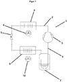
- FIG. 1 shows a refrigerant circuit of an air conditioner according to the invention, which is generally designated by the reference numeral 1.
- the air conditioning is installed on the roof of a train not shown in the figure.
- the refrigerant circuit 1 comprises a piping system 2 with a compressor 3, an outdoor heat exchanger 4, an electronically controlled active throttle valve 5, an internal heat exchanger 6, a liquid separator 7 and a suction pipe 8.
- Parallel to the throttle valve 5 is a thin capillary, not shown in the figure, the the pressure equalization at standstill of the system is used.
- the outdoor heat exchanger 4 is in thermal communication with the environment of the train and gives off heat to the environment during cooling operation.
- an outdoor fan 9 is assigned.
- the indoor heat exchanger 6 is in thermal communication with the passenger compartment of the train and absorbs heat from the passenger compartment during cooling operation.
- the interior heat exchanger 6 is associated with a fan 10 which communicates with a control unit not shown in the figure and is designed for a standstill operation according to the invention, which will be described in more detail below.
- the fan 10 is also in communication with the vehicle battery. Further, a not shown in the figure photovoltaic module is provided with a storage battery to the fan 10 in Supply the following standstill operation, described in detail below, when available, and protect the vehicle battery.
- the refrigerant circuit 1 is designed for operation with CO 2 as a process gas or refrigerant.
- the maximum operating pressure is 120 bar.
- the predetermined for the operation of the refrigerant circuit normal ratio of the filling weight of CO 2 to the internal volume of the refrigerant circuit 1 is such that then critical pressures can occur when the process gas temperature in the entire refrigerant circuit exceeds 65 ° C. Such a high temperature and homogeneous temperature distribution of the refrigerant can be adjusted after a longer standstill of the refrigerant circuit 1.
- the air conditioner shown schematically comprises a pressure sensor, not shown in the figure, for determining the internal pressure in the refrigerant circuit 1.
- the pressure sensor is connected to the control unit.
- an algorithm is stored, which specifies a recording of the operation of the fan 10 at standstill of the air conditioning, if after a certain grace period after switching off the air conditioner, the standstill pressure exceeds a pressure threshold of 95 bar.
- the standstill operation is continued until the pressure threshold is either fallen below again or the air conditioner is put back into operation. Due to the standstill operation, a critical increase in the standstill pressure with increasing temperature can be delayed by a significant amount of time.
- FIG. 2 shows a refrigerant circuit 1 of another embodiment of an air conditioner according to the invention. Identical parts are provided with the same reference numerals.
- the difference to the refrigerant circuit according to FIG. 1 lies in this embodiment in that the liquid separator 7 and the suction tube 8 are covered with thermal storage 11 and 12 respectively.
- the thermal storage 11 and 12 comprise a phase change material in the form of a hydrocarbon wax whose phase transition temperature is solid / liquid at 55 ° C.
- the use of the thermal stores 11 and 12 can delay a critical increase in standstill pressure with increasing temperature by a significant amount of time, thereby assisting the delay achieved by the standstill operation of the fan 10.
Landscapes
- Engineering & Computer Science (AREA)
- Mechanical Engineering (AREA)
- Physics & Mathematics (AREA)
- Thermal Sciences (AREA)
- Air-Conditioning For Vehicles (AREA)
Applications Claiming Priority (1)
| Application Number | Priority Date | Filing Date | Title |
|---|---|---|---|
| DE102017001914.2A DE102017001914A1 (de) | 2017-02-27 | 2017-02-27 | Klimaanlage für ein Fahrzeug |
Publications (3)
| Publication Number | Publication Date |
|---|---|
| EP3366502A2 true EP3366502A2 (fr) | 2018-08-29 |
| EP3366502A3 EP3366502A3 (fr) | 2018-11-14 |
| EP3366502B1 EP3366502B1 (fr) | 2023-05-17 |
Family
ID=61244461
Family Applications (1)
| Application Number | Title | Priority Date | Filing Date |
|---|---|---|---|
| EP18157379.1A Active EP3366502B1 (fr) | 2017-02-27 | 2018-02-19 | Installation de climatisation pour un véhicule |
Country Status (2)
| Country | Link |
|---|---|
| EP (1) | EP3366502B1 (fr) |
| DE (1) | DE102017001914A1 (fr) |
Cited By (1)
| Publication number | Priority date | Publication date | Assignee | Title |
|---|---|---|---|---|
| CN111319645A (zh) * | 2020-03-30 | 2020-06-23 | 中车大连机车研究所有限公司 | 一种机车用co2冷媒空调控制系统 |
Families Citing this family (2)
| Publication number | Priority date | Publication date | Assignee | Title |
|---|---|---|---|---|
| DE102020100296A1 (de) | 2020-01-09 | 2021-07-15 | Knorr-Bremse Systeme für Schienenfahrzeuge GmbH | Kompressorsystem und Verfahren zum Betreiben eines Kompressorsystems in Abhängigkeit des Druckluftbedarfs eines Betriebszustands des Fahrzeugs |
| DE102022118623A1 (de) * | 2022-07-26 | 2024-02-01 | Audi Aktiengesellschaft | Verfahren zum Betreiben einer Kälteanlage mit überkritisch arbeitendem Kältemittel, Kälteanlage und Kraftfahrzeug mit Kälteanlage |
Family Cites Families (9)
| Publication number | Priority date | Publication date | Assignee | Title |
|---|---|---|---|---|
| IT1266773B1 (it) | 1993-11-05 | 1997-01-21 | Franco Formenti | Dispositivo di protezione per compressori frigoriferi |
| DE19743828A1 (de) | 1997-10-03 | 1999-04-08 | Behr Gmbh & Co | Verfahren zum Betrieb einer Klimaanlage mit Kompressor und Kondensatorgebläse |
| DE10062824A1 (de) | 2000-12-15 | 2002-06-27 | Obrist Engineering Gmbh Lusten | Klimaanlage |
| DE10323813A1 (de) * | 2003-05-23 | 2004-12-09 | Behr Gmbh & Co. Kg | Verfahren und Vorrichtung zur Steuerung einer Einrichtung zum Austausch von Wärme |
| DE102006016166A1 (de) * | 2006-04-06 | 2007-10-11 | GM Global Technology Operations, Inc., Detroit | Klimaanlage in einem Kraftfahrzeug |
| DE102007043162B4 (de) | 2006-09-14 | 2021-02-25 | Konvekta Ag | Klimaanlage mit automatischer Kältemittelverlagerung |
| DE102008047753B4 (de) | 2008-09-17 | 2015-10-08 | Konvekta Ag | Kälteanlage mit durch Kaskadenwärmetauscher gekoppelten Kältekreisen |
| DE102014215574B4 (de) * | 2014-08-06 | 2017-10-26 | Siemens Aktiengesellschaft | Fahrzeug, insbesondere Schienenfahrzeug, mit Klimatisierungseinrichtung |
| DE102016110443B4 (de) | 2016-06-06 | 2018-03-29 | Konvekta Aktiengesellschaft | Kälteanlage, Kälteanlagensystem und Verfahren mit Kältemittelverlagerung |
-
2017
- 2017-02-27 DE DE102017001914.2A patent/DE102017001914A1/de not_active Withdrawn
-
2018
- 2018-02-19 EP EP18157379.1A patent/EP3366502B1/fr active Active
Cited By (1)
| Publication number | Priority date | Publication date | Assignee | Title |
|---|---|---|---|---|
| CN111319645A (zh) * | 2020-03-30 | 2020-06-23 | 中车大连机车研究所有限公司 | 一种机车用co2冷媒空调控制系统 |
Also Published As
| Publication number | Publication date |
|---|---|
| EP3366502B1 (fr) | 2023-05-17 |
| DE102017001914A1 (de) | 2018-08-30 |
| EP3366502A3 (fr) | 2018-11-14 |
Similar Documents
| Publication | Publication Date | Title |
|---|---|---|
| EP3697635B1 (fr) | Procédé servant à faire fonctionner un circuit frigorifique ainsi qu'une installation de réfrigération de véhicule | |
| DE102011118162C5 (de) | Kombinierte Kälteanlage und Wärmepumpe und Verfahren zum Betreiben der Anlage mit funktionsabhängiger Kältemittelverlagerung innerhalb des Kältemittelkreislaufes | |
| DE102009011797B4 (de) | Verfahren zum Betreiben eines Kühlsystems sowie Kühlsystem | |
| WO2002092368A1 (fr) | Installation de climatisation | |
| DE102019119272B4 (de) | Gesicherte Kälteanlage, bodengebundenes Fahrzeug damit und Verfahren dafür | |
| DE102012004094B3 (de) | Vorrichtung, insbesondere Wärmepumpe, mit einem in einem Kreislauf geführten Kältemittel sowie Verfahren zum Betrieb einer derartigen Vorrichtung | |
| DE102014219514A1 (de) | Anlagen-Aus-Konfiguration für eine Klimaanlage | |
| DE102011118078A1 (de) | Wärmetauscher, Kühlsystem sowie Verfahren zum Betreiben eines Wärmetauschers und eines Kühlsystems | |
| EP3366502B1 (fr) | Installation de climatisation pour un véhicule | |
| WO2022084322A1 (fr) | Procédé de fonctionnement d'un système de réfrigération à fonction de pompe à chaleur et fonction de régénération pour sources de chaleur, système de réfrigération et véhicule à moteur comprenant un tel système de réfrigération | |
| DE102005007551B4 (de) | Verfahren zum Betreiben eines Tieftemperatur-Flüssiggasspeichertanks | |
| DE102015222778A1 (de) | Kraftfahrzeug mit Ausströmöffnungen für Brennstoff und Verfahren zum Ablassen von Brennstoff | |
| EP4078050B1 (fr) | Contrôle de refroidissement pour un processus de réchauffage destiné à commander un système de refroidissement pour un véhicule à moteur, système de refroidissement, et véhicule à moteur ayant un tel système de refroidissement | |
| DE102014108454B4 (de) | Kältemittelkreislauf mit einer Bypassleitung | |
| DE102020117133B4 (de) | Verfahren zum Betreiben einer Kälteanlage eines Kraftfahrzeugs und Kälteanlage mit Rückströmungsverhinderung | |
| EP1600314B1 (fr) | Arrangement et procédé d'operation dans un circuit de réfrigérant | |
| DE102009022765A1 (de) | Solaranlage für eine Heiz- oder Kühlanlage | |
| AT504135B1 (de) | Verfahren zur wärmerückgewinnung | |
| DE102019133489A1 (de) | Nachheizverfahren zum Betreiben einer Kälteanlage für ein Kraftfahrzeug, Kälteanlage und Kraftfahrzeug mit einer solchen Kälteanlage | |
| DE102014105612B4 (de) | Fahrzeug-Klimasystem und Verfahren zum Betrieb eines Fahrzeug-Klimasystems | |
| EP3767187B1 (fr) | Procédé de commande d'un ensemble de pompes à chaleur | |
| AT513855B1 (de) | Verfahren zum Steuern einer Klimaanlage | |
| DE102007052259A1 (de) | Kraftstoffversorgungseinrichtung für ein mit Wasserstoff zu betreibendes Kraftfahrzeug | |
| DE102014117149A1 (de) | Dezentrale Anlage für die Klimatisierung von Aufenthaltsräumen mit einem raumseitigen Anlagenteil und einem außenseitigen Anlagenteil | |
| DE102023112282B3 (de) | Verfahren zum Betreiben eines Kühlsystems eines Hybridkraftfahrzeugs sowie Hybridkraftfahrzeug |
Legal Events
| Date | Code | Title | Description |
|---|---|---|---|
| PUAI | Public reference made under article 153(3) epc to a published international application that has entered the european phase |
Free format text: ORIGINAL CODE: 0009012 |
|
| STAA | Information on the status of an ep patent application or granted ep patent |
Free format text: STATUS: THE APPLICATION HAS BEEN PUBLISHED |
|
| AK | Designated contracting states |
Kind code of ref document: A2 Designated state(s): AL AT BE BG CH CY CZ DE DK EE ES FI FR GB GR HR HU IE IS IT LI LT LU LV MC MK MT NL NO PL PT RO RS SE SI SK SM TR |
|
| AX | Request for extension of the european patent |
Extension state: BA ME |
|
| PUAL | Search report despatched |
Free format text: ORIGINAL CODE: 0009013 |
|
| AK | Designated contracting states |
Kind code of ref document: A3 Designated state(s): AL AT BE BG CH CY CZ DE DK EE ES FI FR GB GR HR HU IE IS IT LI LT LU LV MC MK MT NL NO PL PT RO RS SE SI SK SM TR |
|
| AX | Request for extension of the european patent |
Extension state: BA ME |
|
| RIC1 | Information provided on ipc code assigned before grant |
Ipc: B60H 1/00 20060101AFI20181009BHEP Ipc: B60H 1/32 20060101ALI20181009BHEP Ipc: B61D 27/00 20060101ALI20181009BHEP |
|
| STAA | Information on the status of an ep patent application or granted ep patent |
Free format text: STATUS: REQUEST FOR EXAMINATION WAS MADE |
|
| 17P | Request for examination filed |
Effective date: 20190513 |
|
| STAA | Information on the status of an ep patent application or granted ep patent |
Free format text: STATUS: EXAMINATION IS IN PROGRESS |
|
| 17Q | First examination report despatched |
Effective date: 20200507 |
|
| GRAP | Despatch of communication of intention to grant a patent |
Free format text: ORIGINAL CODE: EPIDOSNIGR1 |
|
| STAA | Information on the status of an ep patent application or granted ep patent |
Free format text: STATUS: GRANT OF PATENT IS INTENDED |
|
| INTG | Intention to grant announced |
Effective date: 20230113 |
|
| GRAS | Grant fee paid |
Free format text: ORIGINAL CODE: EPIDOSNIGR3 |
|
| GRAA | (expected) grant |
Free format text: ORIGINAL CODE: 0009210 |
|
| STAA | Information on the status of an ep patent application or granted ep patent |
Free format text: STATUS: THE PATENT HAS BEEN GRANTED |
|
| AK | Designated contracting states |
Kind code of ref document: B1 Designated state(s): AL AT BE BG CH CY CZ DE DK EE ES FI FR GB GR HR HU IE IS IT LI LT LU LV MC MK MT NL NO PL PT RO RS SE SI SK SM TR |
|
| REG | Reference to a national code |
Ref country code: GB Ref legal event code: FG4D Free format text: NOT ENGLISH |
|
| REG | Reference to a national code |
Ref country code: DE Ref legal event code: R096 Ref document number: 502018012151 Country of ref document: DE |
|
| REG | Reference to a national code |
Ref country code: CH Ref legal event code: EP |
|
| REG | Reference to a national code |
Ref country code: IE Ref legal event code: FG4D Free format text: LANGUAGE OF EP DOCUMENT: GERMAN |
|
| REG | Reference to a national code |
Ref country code: AT Ref legal event code: REF Ref document number: 1568266 Country of ref document: AT Kind code of ref document: T Effective date: 20230615 |
|
| REG | Reference to a national code |
Ref country code: LT Ref legal event code: MG9D |
|
| REG | Reference to a national code |
Ref country code: NL Ref legal event code: MP Effective date: 20230517 |
|
| PG25 | Lapsed in a contracting state [announced via postgrant information from national office to epo] |
Ref country code: SE Free format text: LAPSE BECAUSE OF FAILURE TO SUBMIT A TRANSLATION OF THE DESCRIPTION OR TO PAY THE FEE WITHIN THE PRESCRIBED TIME-LIMIT Effective date: 20230517 Ref country code: PT Free format text: LAPSE BECAUSE OF FAILURE TO SUBMIT A TRANSLATION OF THE DESCRIPTION OR TO PAY THE FEE WITHIN THE PRESCRIBED TIME-LIMIT Effective date: 20230918 Ref country code: NO Free format text: LAPSE BECAUSE OF FAILURE TO SUBMIT A TRANSLATION OF THE DESCRIPTION OR TO PAY THE FEE WITHIN THE PRESCRIBED TIME-LIMIT Effective date: 20230817 Ref country code: NL Free format text: LAPSE BECAUSE OF FAILURE TO SUBMIT A TRANSLATION OF THE DESCRIPTION OR TO PAY THE FEE WITHIN THE PRESCRIBED TIME-LIMIT Effective date: 20230517 Ref country code: ES Free format text: LAPSE BECAUSE OF FAILURE TO SUBMIT A TRANSLATION OF THE DESCRIPTION OR TO PAY THE FEE WITHIN THE PRESCRIBED TIME-LIMIT Effective date: 20230517 |
|
| PG25 | Lapsed in a contracting state [announced via postgrant information from national office to epo] |
Ref country code: RS Free format text: LAPSE BECAUSE OF FAILURE TO SUBMIT A TRANSLATION OF THE DESCRIPTION OR TO PAY THE FEE WITHIN THE PRESCRIBED TIME-LIMIT Effective date: 20230517 Ref country code: PL Free format text: LAPSE BECAUSE OF FAILURE TO SUBMIT A TRANSLATION OF THE DESCRIPTION OR TO PAY THE FEE WITHIN THE PRESCRIBED TIME-LIMIT Effective date: 20230517 Ref country code: LV Free format text: LAPSE BECAUSE OF FAILURE TO SUBMIT A TRANSLATION OF THE DESCRIPTION OR TO PAY THE FEE WITHIN THE PRESCRIBED TIME-LIMIT Effective date: 20230517 Ref country code: LT Free format text: LAPSE BECAUSE OF FAILURE TO SUBMIT A TRANSLATION OF THE DESCRIPTION OR TO PAY THE FEE WITHIN THE PRESCRIBED TIME-LIMIT Effective date: 20230517 Ref country code: IS Free format text: LAPSE BECAUSE OF FAILURE TO SUBMIT A TRANSLATION OF THE DESCRIPTION OR TO PAY THE FEE WITHIN THE PRESCRIBED TIME-LIMIT Effective date: 20230917 Ref country code: HR Free format text: LAPSE BECAUSE OF FAILURE TO SUBMIT A TRANSLATION OF THE DESCRIPTION OR TO PAY THE FEE WITHIN THE PRESCRIBED TIME-LIMIT Effective date: 20230517 Ref country code: GR Free format text: LAPSE BECAUSE OF FAILURE TO SUBMIT A TRANSLATION OF THE DESCRIPTION OR TO PAY THE FEE WITHIN THE PRESCRIBED TIME-LIMIT Effective date: 20230818 |
|
| PG25 | Lapsed in a contracting state [announced via postgrant information from national office to epo] |
Ref country code: FI Free format text: LAPSE BECAUSE OF FAILURE TO SUBMIT A TRANSLATION OF THE DESCRIPTION OR TO PAY THE FEE WITHIN THE PRESCRIBED TIME-LIMIT Effective date: 20230517 |
|
| PG25 | Lapsed in a contracting state [announced via postgrant information from national office to epo] |
Ref country code: SK Free format text: LAPSE BECAUSE OF FAILURE TO SUBMIT A TRANSLATION OF THE DESCRIPTION OR TO PAY THE FEE WITHIN THE PRESCRIBED TIME-LIMIT Effective date: 20230517 |
|
| PG25 | Lapsed in a contracting state [announced via postgrant information from national office to epo] |
Ref country code: SM Free format text: LAPSE BECAUSE OF FAILURE TO SUBMIT A TRANSLATION OF THE DESCRIPTION OR TO PAY THE FEE WITHIN THE PRESCRIBED TIME-LIMIT Effective date: 20230517 Ref country code: SK Free format text: LAPSE BECAUSE OF FAILURE TO SUBMIT A TRANSLATION OF THE DESCRIPTION OR TO PAY THE FEE WITHIN THE PRESCRIBED TIME-LIMIT Effective date: 20230517 Ref country code: RO Free format text: LAPSE BECAUSE OF FAILURE TO SUBMIT A TRANSLATION OF THE DESCRIPTION OR TO PAY THE FEE WITHIN THE PRESCRIBED TIME-LIMIT Effective date: 20230517 Ref country code: EE Free format text: LAPSE BECAUSE OF FAILURE TO SUBMIT A TRANSLATION OF THE DESCRIPTION OR TO PAY THE FEE WITHIN THE PRESCRIBED TIME-LIMIT Effective date: 20230517 Ref country code: DK Free format text: LAPSE BECAUSE OF FAILURE TO SUBMIT A TRANSLATION OF THE DESCRIPTION OR TO PAY THE FEE WITHIN THE PRESCRIBED TIME-LIMIT Effective date: 20230517 Ref country code: CZ Free format text: LAPSE BECAUSE OF FAILURE TO SUBMIT A TRANSLATION OF THE DESCRIPTION OR TO PAY THE FEE WITHIN THE PRESCRIBED TIME-LIMIT Effective date: 20230517 |
|
| REG | Reference to a national code |
Ref country code: DE Ref legal event code: R097 Ref document number: 502018012151 Country of ref document: DE |
|
| PLBE | No opposition filed within time limit |
Free format text: ORIGINAL CODE: 0009261 |
|
| STAA | Information on the status of an ep patent application or granted ep patent |
Free format text: STATUS: NO OPPOSITION FILED WITHIN TIME LIMIT |
|
| 26N | No opposition filed |
Effective date: 20240220 |
|
| PG25 | Lapsed in a contracting state [announced via postgrant information from national office to epo] |
Ref country code: SI Free format text: LAPSE BECAUSE OF FAILURE TO SUBMIT A TRANSLATION OF THE DESCRIPTION OR TO PAY THE FEE WITHIN THE PRESCRIBED TIME-LIMIT Effective date: 20230517 |
|
| PG25 | Lapsed in a contracting state [announced via postgrant information from national office to epo] |
Ref country code: SI Free format text: LAPSE BECAUSE OF FAILURE TO SUBMIT A TRANSLATION OF THE DESCRIPTION OR TO PAY THE FEE WITHIN THE PRESCRIBED TIME-LIMIT Effective date: 20230517 Ref country code: IT Free format text: LAPSE BECAUSE OF FAILURE TO SUBMIT A TRANSLATION OF THE DESCRIPTION OR TO PAY THE FEE WITHIN THE PRESCRIBED TIME-LIMIT Effective date: 20230517 |
|
| PG25 | Lapsed in a contracting state [announced via postgrant information from national office to epo] |
Ref country code: MC Free format text: LAPSE BECAUSE OF FAILURE TO SUBMIT A TRANSLATION OF THE DESCRIPTION OR TO PAY THE FEE WITHIN THE PRESCRIBED TIME-LIMIT Effective date: 20230517 |
|
| PG25 | Lapsed in a contracting state [announced via postgrant information from national office to epo] |
Ref country code: LU Free format text: LAPSE BECAUSE OF NON-PAYMENT OF DUE FEES Effective date: 20240219 |
|
| GBPC | Gb: european patent ceased through non-payment of renewal fee |
Effective date: 20240219 |
|
| PG25 | Lapsed in a contracting state [announced via postgrant information from national office to epo] |
Ref country code: LU Free format text: LAPSE BECAUSE OF NON-PAYMENT OF DUE FEES Effective date: 20240219 |
|
| PG25 | Lapsed in a contracting state [announced via postgrant information from national office to epo] |
Ref country code: BG Free format text: LAPSE BECAUSE OF FAILURE TO SUBMIT A TRANSLATION OF THE DESCRIPTION OR TO PAY THE FEE WITHIN THE PRESCRIBED TIME-LIMIT Effective date: 20230517 |
|
| PG25 | Lapsed in a contracting state [announced via postgrant information from national office to epo] |
Ref country code: BG Free format text: LAPSE BECAUSE OF FAILURE TO SUBMIT A TRANSLATION OF THE DESCRIPTION OR TO PAY THE FEE WITHIN THE PRESCRIBED TIME-LIMIT Effective date: 20230517 |
|
| REG | Reference to a national code |
Ref country code: BE Ref legal event code: MM Effective date: 20240229 |
|
| PG25 | Lapsed in a contracting state [announced via postgrant information from national office to epo] |
Ref country code: BE Free format text: LAPSE BECAUSE OF NON-PAYMENT OF DUE FEES Effective date: 20240229 |
|
| PG25 | Lapsed in a contracting state [announced via postgrant information from national office to epo] |
Ref country code: GB Free format text: LAPSE BECAUSE OF NON-PAYMENT OF DUE FEES Effective date: 20240219 |
|
| PG25 | Lapsed in a contracting state [announced via postgrant information from national office to epo] |
Ref country code: IE Free format text: LAPSE BECAUSE OF NON-PAYMENT OF DUE FEES Effective date: 20240219 |
|
| PG25 | Lapsed in a contracting state [announced via postgrant information from national office to epo] |
Ref country code: IE Free format text: LAPSE BECAUSE OF NON-PAYMENT OF DUE FEES Effective date: 20240219 Ref country code: GB Free format text: LAPSE BECAUSE OF NON-PAYMENT OF DUE FEES Effective date: 20240219 Ref country code: BE Free format text: LAPSE BECAUSE OF NON-PAYMENT OF DUE FEES Effective date: 20240229 |
|
| PGFP | Annual fee paid to national office [announced via postgrant information from national office to epo] |
Ref country code: DE Payment date: 20250225 Year of fee payment: 8 |
|
| PG25 | Lapsed in a contracting state [announced via postgrant information from national office to epo] |
Ref country code: CY Free format text: LAPSE BECAUSE OF FAILURE TO SUBMIT A TRANSLATION OF THE DESCRIPTION OR TO PAY THE FEE WITHIN THE PRESCRIBED TIME-LIMIT; INVALID AB INITIO Effective date: 20180219 |
|
| PG25 | Lapsed in a contracting state [announced via postgrant information from national office to epo] |
Ref country code: HU Free format text: LAPSE BECAUSE OF FAILURE TO SUBMIT A TRANSLATION OF THE DESCRIPTION OR TO PAY THE FEE WITHIN THE PRESCRIBED TIME-LIMIT; INVALID AB INITIO Effective date: 20180219 |
|
| PG25 | Lapsed in a contracting state [announced via postgrant information from national office to epo] |
Ref country code: TR Free format text: LAPSE BECAUSE OF FAILURE TO SUBMIT A TRANSLATION OF THE DESCRIPTION OR TO PAY THE FEE WITHIN THE PRESCRIBED TIME-LIMIT Effective date: 20230517 |
|
| REG | Reference to a national code |
Ref country code: CH Ref legal event code: U11 Free format text: ST27 STATUS EVENT CODE: U-0-0-U10-U11 (AS PROVIDED BY THE NATIONAL OFFICE) Effective date: 20260325 |
|
| PGFP | Annual fee paid to national office [announced via postgrant information from national office to epo] |
Ref country code: AT Payment date: 20260331 Year of fee payment: 9 |
|
| PGFP | Annual fee paid to national office [announced via postgrant information from national office to epo] |
Ref country code: FR Payment date: 20260320 Year of fee payment: 9 |
|
| PGFP | Annual fee paid to national office [announced via postgrant information from national office to epo] |
Ref country code: CH Payment date: 20260325 Year of fee payment: 9 |