EP3366571B1 - Propulseur passif de couche limite - Google Patents
Propulseur passif de couche limite Download PDFInfo
- Publication number
- EP3366571B1 EP3366571B1 EP18157589.5A EP18157589A EP3366571B1 EP 3366571 B1 EP3366571 B1 EP 3366571B1 EP 18157589 A EP18157589 A EP 18157589A EP 3366571 B1 EP3366571 B1 EP 3366571B1
- Authority
- EP
- European Patent Office
- Prior art keywords
- boundary layer
- propulsor
- radially
- aerofoil
- aerofoil blades
- Prior art date
- Legal status (The legal status is an assumption and is not a legal conclusion. Google has not performed a legal analysis and makes no representation as to the accuracy of the status listed.)
- Active
Links
Images

Classifications
-
- B—PERFORMING OPERATIONS; TRANSPORTING
- B64—AIRCRAFT; AVIATION; COSMONAUTICS
- B64C—AEROPLANES; HELICOPTERS
- B64C11/00—Propellers, e.g. of ducted type; Features common to propellers and rotors for rotorcraft
- B64C11/16—Blades
- B64C11/18—Aerodynamic features
-
- B—PERFORMING OPERATIONS; TRANSPORTING
- B64—AIRCRAFT; AVIATION; COSMONAUTICS
- B64C—AEROPLANES; HELICOPTERS
- B64C11/00—Propellers, e.g. of ducted type; Features common to propellers and rotors for rotorcraft
- B64C11/46—Arrangements of, or constructional features peculiar to, multiple propellers
- B64C11/48—Units of two or more coaxial propellers
-
- B—PERFORMING OPERATIONS; TRANSPORTING
- B64—AIRCRAFT; AVIATION; COSMONAUTICS
- B64C—AEROPLANES; HELICOPTERS
- B64C21/00—Influencing air flow over aircraft surfaces by affecting boundary layer flow
-
- B—PERFORMING OPERATIONS; TRANSPORTING
- B64—AIRCRAFT; AVIATION; COSMONAUTICS
- B64C—AEROPLANES; HELICOPTERS
- B64C21/00—Influencing air flow over aircraft surfaces by affecting boundary layer flow
- B64C21/01—Boundary layer ingestion [BLI] propulsion
-
- B—PERFORMING OPERATIONS; TRANSPORTING
- B64—AIRCRAFT; AVIATION; COSMONAUTICS
- B64D—EQUIPMENT FOR FITTING IN OR TO AIRCRAFT; FLIGHT SUITS; PARACHUTES; ARRANGEMENT OR MOUNTING OF POWER PLANTS OR PROPULSION TRANSMISSIONS IN AIRCRAFT
- B64D27/00—Arrangement or mounting of power plants in aircraft; Aircraft characterised by the type or position of power plants
- B64D27/02—Aircraft characterised by the type or position of power plants
-
- B—PERFORMING OPERATIONS; TRANSPORTING
- B64—AIRCRAFT; AVIATION; COSMONAUTICS
- B64C—AEROPLANES; HELICOPTERS
- B64C2230/00—Boundary layer controls
-
- B—PERFORMING OPERATIONS; TRANSPORTING
- B64—AIRCRAFT; AVIATION; COSMONAUTICS
- B64C—AEROPLANES; HELICOPTERS
- B64C2230/00—Boundary layer controls
- B64C2230/04—Boundary layer controls by actively generating fluid flow
-
- Y—GENERAL TAGGING OF NEW TECHNOLOGICAL DEVELOPMENTS; GENERAL TAGGING OF CROSS-SECTIONAL TECHNOLOGIES SPANNING OVER SEVERAL SECTIONS OF THE IPC; TECHNICAL SUBJECTS COVERED BY FORMER USPC CROSS-REFERENCE ART COLLECTIONS [XRACs] AND DIGESTS
- Y02—TECHNOLOGIES OR APPLICATIONS FOR MITIGATION OR ADAPTATION AGAINST CLIMATE CHANGE
- Y02T—CLIMATE CHANGE MITIGATION TECHNOLOGIES RELATED TO TRANSPORTATION
- Y02T50/00—Aeronautics or air transport
- Y02T50/10—Drag reduction
Definitions
- the present disclosure relates to a passive boundary layer propulsor and particularly, but not exclusively, to a passive boundary layer propulsor for an aircraft.
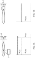
- FIG. 1A A schematic example is shown in Figure 1A in which ⁇ surface represents the dissipation that occurs due to skin friction, and ⁇ wake represents the dissipation that occurs due to wake mixing.
- Fuselage Boundary Layer Ingestion places the aircraft's engine at or immediately behind the tail of the aircraft so as to ingest the boundary layer flow as it leaves the aircraft's fuselage surface. In this way, the downstream mixing losses in the fuselage wake can be eliminated or significantly reduced as illustrated in Figure 1B .
- US 4,927,331 A discloses a blade for a shrouded propeller in which its aerodynamically active part presents a rectangular shape.
- the maximum relative camber of the successive profiles constituting the aerodynamically active part of the blade increases from a value close to 0 to a value close to 0.04.
- the twist of the aerodynamically active part of the blade decreases from a first value close to 12° to a second value close to 4°, then increases to a third value close to 4.5°.
- the maximum relative thickness of the successive profiles decreases from a value close to 13.5% to a value close to 9.5%.
- GB 873 851 A discloses a means for improving the propulsion of streamlined bodies, such as aircraft and submarines, which have a surface region where a transition of boundary layer flow from laminar to turbulent occurs.
- the streamlined body comprises a power operated propulsion means at the rear of the body arranged coaxially with the axis of symmetry of the body, a first tubular element coaxial with and radially spaced from the propulsion means, and a second tubular element surrounding a rear part of the body aft of said region and radially spaced therefrom to define an annular passage.
- the second element has an external diameter smaller than that of the first element and has a longitudinal section shaped to accelerate the fluid flow induced through the passage by the propulsion means.
- a screw propeller and impeller provide forward motion, and vanes straighten the fluid flow from the impeller.
- US 4,911,612 A discloses a section for shrouded propeller blade having a relative thickness of between 9% and 15%.
- the curvature of the section has a maximum value at the leading edge.
- the upper surface line comprises three successive portions. In the first portion, the curvature decreases rapidly from said maximum value at the leading edge to a value close to 20 at a first point of which the reduced abscissa is close to 1%. In the second portion, the curvature decreases more slowly from the value close to 20 at the first point up to a value close to 1 at a second point, of which the reduced abscissa is close to 25 percent. In the third portion, the curvature is less than 1 between the second point and the trailing edge.
- EP 3 048 042 A1 discloses a gas-electric propulsion system for an aircraft.
- the system may include a turbofan jet engine, an electric powered boundary layer ingestion fan that is coupled to a fuselage portion of the aircraft aft of the turbofan jet engine, and an electric generator that is electronically coupled to the turbofan jet engine and to the boundary layer ingestion fan.
- the electric generator converts rotational energy from the turbofan jet engine to electrical energy and provides at least a portion of the electrical energy to the boundary layer ingestion fan.
- a boundary layer propulsor configured to be mounted to a tail of an aircraft, the propulsor comprising:
- the boundary layer propulsor of the present disclosure is a passive boundary layer propulsor. In other words the propulsor is not actively powered by an engine or other equivalent source of motive power.
- the radially proximal portions extend radially from the rotor to a distance approximately equal to a thickness of the boundary layer that is generated when the aircraft is in its normal operating conditions.
- the boundary layer propulsor is powered by an air flow passing over the radially distal portions of the aerofoil blades.
- the radially distal portions of the aerofoil blades are configured as a turbine.
- the radially distal portions of the aerofoil blades extract energy from the air flow passing over the aerofoil blades.
- the radially proximal portions of the aerofoil blades are configured as a compressor.
- the radially proximal portions of the aerofoil blades accelerate the low momentum flow at the base of the boundary layer to thereby minimise the mixing losses resulting from the boundary layer detaching from the surface of the aircraft.
- the plurality of first aerofoil blades may be arranged to fold such that the axis of each first aerofoil blade is aligned to be approximately parallel with the axis of rotation.
- the first cambered cross-section is a negative camber
- the third cambered cross-section is a positive camber
- the radially distal portions of the aerofoil blades are provided with a positively cambered cross-section. In this way, the radially distal portions of the aerofoil blades are configured as a turbine array.
- the radially proximal portions of the aerofoil blades are provided with a negatively cambered cross-section. In this way, the radially proximal portions of the aerofoil blades are configured as a compressor array.
- each first aerofoil blade has a first surface and an opposite second surface, each of the first surface and second surface being provided with a smoothed transition between the radially proximal portion and the middle portion, and between the middle portion and the radially distal portion.
- the plurality of first aerofoil blades comprises between two and six first aerofoil blades.
- the plurality of first aerofoil blades is equi-spaced around the axis of rotation. Equi-spacing the first aerofoil blades simplifies the manufacture of the propulsor.
- the first aerofoil blades are unevenly spaced around the axis of rotation. This uneven spacing will reduce vibration and/or noise generation problems.
- a boundary layer propulsor according to the first aspect and further comprising:
- the boundary layer propulsor comprises two first aerofoil blades and eight second aerofoil blades.
- the use of more second aerofoil blades increases the efficiency of the propulsor at accelerating the boundary layer flow and so reduces the associated wake losses.
- a radial length of each second aerofoil blade is equal to a radial length of each radially proximal portion of the first aerofoil blades.
- Each second aerofoil blade is intended only to accelerate the boundary layer flow.
- the plurality of second aerofoil blades is equi-spaced radially between the first aerofoil blades.
- each of the first aerofoil blades has a first chord length, and the first chord length decreases from the radially innermost end of the first aerofoil blade to the radially outermost end of the first aerofoil blade.
- the mechanical loading experienced by the first aerofoil blades will be greater at the rotor end (i.e. at a proximal end) than at the tip (i.e. at a distal end). Consequently, the weight efficiency of the first aerofoil blades may be improved by making the chord of the first aerofoil blade wider at the proximal end than at the distal end.
- a boundary layer propulsion system comprising:
- the boundary layer propulsion system uses energy drawn from the free stream passing over the machine body to impart rotation to the boundary layer propulsor via the free stream interaction with the radially distal portions of the first aerofoil blades.
- the rotation of the boundary layer propulsor then accelerates the boundary layer flow over the machine body by the rotation of the radially proximal portions of the first aerofoil blades.
- boundary layer propulsion system can increase the efficiency of the powered machine body making it attractive for a user.
- the boundary layer propulsor according to the first aspect comprises the boundary layer propulsor according to the second aspect, and wherein the rotation of the boundary layer propulsor relative to the machine body causes the second aerofoil blades to entrain a boundary layer flow passing over the surface of the machine body to thereby accelerate the boundary layer flow.
- supplementary second aerofoil blades increases the degree of acceleration that can be imparted to the boundary layer flow by the boundary layer propulsor so increasing the amount by which the mixing losses (as the boundary layer flow leaves the machine body) are reduced.
- an aircraft comprising a boundary layer propulsion system according to the third aspect.
- the boundary layer propulsor is positioned at the rearmost portion of the fuselage of the aircraft. This positioning provides the aircraft with additional stability which in turn enables the vertical and/or horizontal stabiliser surfaces of the aircraft to be reduced in area. This reduces the aerodynamic losses associated with these stabilising surfaces so increasing the aerodynamic efficiency of the aircraft.
- This rearmost positioning of the boundary layer propulsor means that the plane of the first aerofoil blades and the plane of the second aerofoil blades is behind the vertical and horizontal tail surfaces of the aircraft.
- any debris emanating from a failure of the first and/or second aerofoil blades will not impinge on the aircraft's fuselage structure.
- aspects of the disclosure provide devices, methods and systems which include and/or implement some or all of the actions described herein.
- the illustrative aspects of the disclosure are designed to solve one or more of the problems herein described and/or one or more other problems not discussed.
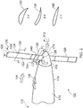
- a boundary layer propulsor according to a first embodiment of the disclosure is designated generally by the reference numeral 100.
- the following disclosure describes the application of the boundary layer propulsor to an aircraft. However, it is to be understood that the boundary layer propulsor of the disclosure may equally be applied to a machine body passing through an alternative fluid flow stream, such as a submersible vessel.
- the machine body 170 has an upstream end 172 and an opposite downstream end 174.
- the boundary layer propulsor 100 has a rotor 110 having an axis of rotation 112, and a plurality of first aerofoil blades 120. Each of the first aerofoil blades 120 extends radially from the rotor 110. The plurality of first aerofoil blades 120 is arranged in a circumferential array around the axis of rotation 112.
- Each first aerofoil blade 120 has, in a radially outward sequence, a radially proximal portion 130, a middle portion 140, and a radially distal portion 150.
- the radially proximal portion 130 has a first cambered cross-section 132
- the middle portion 140 has a second uncambered cross-section 142
- the radially distal portion 150 has a third cambered cross-section 152.
- the first cambered cross-section 132 is cambered in an opposite sense to the third cambered cross-section 152.
- the first cambered cross-section 132 is a negative camber
- the third cambered cross-section 152 is a positive camber.
- the radially distal portion 150 of the first aerofoil blades 120 are configured as a turbine array
- the radially proximal portion 130 of the first aerofoil blades 120 are configured as a compressor array.
- Each first aerofoil blade 120 has a pressure surface 122 and an opposite suction surface 124 with each of the pressure surface 122 and suction surface 124 being provided with a smoothed transition between the radially proximal portion 130 and the middle portion 140, and between the middle portion 140 and the radially distal portion 150.
- Each of the first aerofoil blades 120 has a first chord length 126.
- the first chord length 126 decreases from the radially innermost end 127 of the first aerofoil blade 120 to the radially outermost end 128 of the first aerofoil blade 120.
- the boundary layer propulsor 100 has two first aerofoil blades 120 that are spaced opposite one another around the axis of rotation 112.
- the boundary layer propulsor 100 is mounted to the tail 170 of an aircraft (not shown) and an air flow 114 passes over the surface of the aircraft.
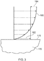
- Figure 3 provides a schematic illustration of the velocity profile of the air flow over a surface 176 of the aircraft tail 170.
- the velocity profile 180 increases from zero at the surface 176 to a free stream velocity 114.
- an amount of energy represented by reference numeral 184 is extracted from the free stream flow 114 to generate rotation of the propulsor and this is transferred to energy (represented by reference numeral 182) used to accelerate the boundary layer flow 116.
- the radially distal portions 150 acting as a turbine array, extract energy from the free stream flow 114 and generate rotation of the boundary layer propulsor 100. This rotation causes the radially proximal portions 130, acting as a compressor array to accelerate the boundary layer flow 116 passing over the surface 176 of the machine body 170.
- This acceleration of the boundary layer flow 116 reduces the mixing losses experienced by the boundary layer flow 116 when it leaves the surface 176 of the aircraft at a downstream end 174.
- a boundary layer propulsor according to a second embodiment of the disclosure is designated generally by the reference numeral 200.
- Features of the boundary layer propulsor 200 which correspond to those of boundary layer propulsor 100 have been given corresponding reference numerals for ease of reference.
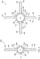
- the boundary layer propulsor 200 has two first aerofoil blades 120, as described above in relation to the first embodiment, and eight second aerofoil blades 160. Each of the second aerofoil blades 160 extends radially from the rotor 110. The second aerofoil blades 160 are arranged in a circumferential array around the axis of rotation 112.
- four of the second aerofoil blades 160 are arranged on each side of the rotor 110 and equi-spaced from the two first aerofoil blades 120.
- Each second aerofoil blade 160 has a fourth cambered cross-section, with the fourth cambered cross-section being cambered in the same sense as the first cambered cross-section 132.
- Each of the second aerofoil blades 160 has a radial length 164 that is equal to a radial length 134 of each radially proximal portion 130 of the first aerofoil blades 120.
- the radially proximal portions 130 of each of the first aerofoil blades 120 together with the second aerofoil blades 160 together define a compressor array.
- boundary layer propulsor 200 operates in the same manner as the boundary layer propulsor 100 that has been described above, with the second aerofoil blades 160 acting to supplement the radially proximal portions 130 of each of the first aerofoil blades 120 in accelerating the boundary layer flow of the surface 176 of the aircraft 170.
- a boundary layer propulsor according to a third embodiment of the disclosure is designated generally by the reference numeral 300.
- Features of the boundary layer propulsor 300 which correspond to those of boundary layer propulsor 100 have been given corresponding reference numerals for ease of reference.
- the boundary layer propulsor 300 has four first aerofoil blades 120, and eight second aerofoil blades 160. Each of the second aerofoil blades 160 extends radially from the rotor 110. The second aerofoil blades 160 are arranged in a circumferential array around the axis of rotation 112.
- two of the second aerofoil blades 160 are positioned in an equi-spaced arrangement between each pair of adjacent first aerofoil blades 120.
- Each second aerofoil blade 160 is as described above in relation to the second embodiment.
- boundary layer propulsor 300 operates in the same manner as the boundary layer propulsor 100 that has been described above, with the second aerofoil blades 160 acting to supplement the radially proximal portions 130 of each of the first aerofoil blades 120 in accelerating the boundary layer flow 116 of the surface 176 of the aircraft 170.
- a boundary layer propulsor according to a fourth embodiment of the disclosure is designated generally by the reference numeral 400.
- Features of the boundary layer propulsor 400 which correspond to those of boundary layer propulsor 100 have been given corresponding reference numerals for ease of reference.
- the boundary layer propulsor 400 has a first rotor 410 and a second rotor 411. Each of the first rotor 410 and the second rotor 411 are co-located in axial sequence on the axis of rotation 112. The second rotor 411 is positioned upstream of the first rotor 410.
- the first rotor 410 has two first aerofoil blades 420. Each of the first aerofoil blades 420 extends radially from the first rotor 410. The first aerofoil blades 420 are equi-spaced around the axis of rotation 112. Each first aerofoil blade 420 is as described above in relation to the first embodiment.
- the second rotor 411 has sixteen second aerofoil blades 460.
- Each of the second aerofoil blades 460 extends radially from the second rotor 411.
- the second aerofoil blades 460 are equi-spaced around the axis of rotation 112.
- Each second aerofoil blade 460 is as described above in relation to the first embodiment.
- Each first aerofoil blade 420 has, in a radially outward sequence, a radially proximal portion 430, a middle portion 440, and a radially distal portion 450.
- the radially proximal portion 430 has a first cambered cross-section 432
- the middle portion 440 has a second uncambered cross-section 442
- the radially distal portion 450 has a third cambered cross-section 452.
- the first cambered cross-section 432 is cambered in an opposite sense to the third cambered cross-section 452.
- the third cambered cross-section 452 is a positive camber, and the first cambered cross-section 432 is a negative camber.
- the radially distal portion 450 of the first aerofoil blades 420 are configured as a turbine array, and the radially proximal portion 430 of the first aerofoil blades 420 are configured as a compressor array.
- Each first aerofoil blade 420 has a pressure surface 422 and an opposite suction surface 424 with each of the pressure surface 422 and suction surface 424 being provided with a smoothed transition between the radially proximal portion 430 and the middle portion 440, and between the middle portion 440 and the radially distal portion 450.
- Each second aerofoil blade 460 has a fourth cambered cross-section 462, with the fourth cambered cross-section 462 being cambered in the same sense as the first cambered cross-section 432.
- Each of the second aerofoil blades 460 has a radial length 464 that is equal to a radial length 434 of each radially proximal portion 430 of the first aerofoil blades 420.
- Rotational drive to the boundary layer propulsor 400 is provided via a shaft 496 from a source of motive power (not shown).
- the source of motive power may be an electric motor, a gas turbine engine, a shaft drive from another engine, or another source.
- the shaft 496 provides an input drive to a gearbox 494.
- a first output drive 490 from the gearbox 494 drives the first rotor 410, and a second output drive 492 from the gearbox 494 droves the second rotor 411.
- the second output drive 492 provides a 4:1 step-up over the first output drive 490.
- boundary layer propulsor 400 operates in the same manner as the boundary layer propulsor 200 that has been described above, with the second aerofoil blades 460 acting to supplement the radially proximal portions 430 of each of the first aerofoil blades 420 in accelerating the boundary layer flow 116 of the surface 176 of the aircraft 170.
- the step-up in speed ratio between the first rotor 410 and the second rotor 411 enables the second rotor and the corresponding second aerofoil blades 460 to generate a higher pressure ratio in the acceleration of the boundary layer flow 116.
- the relatively lower rotational speed of the first aerofoil blades 420 enables them to act effectively as Outlet Guide Vanes in their hub portion and as a turbine array in their tip portion.
Landscapes
- Engineering & Computer Science (AREA)
- Aviation & Aerospace Engineering (AREA)
- Physics & Mathematics (AREA)
- Fluid Mechanics (AREA)
- Chemical & Material Sciences (AREA)
- Combustion & Propulsion (AREA)
- Structures Of Non-Positive Displacement Pumps (AREA)
- Wind Motors (AREA)
Claims (12)
- Propulseur de couche limite (100:200:300) conçu pour être monté sur une queue d'un aéronef, le propulseur comprenant :un rotor (110) possédant un axe de rotation (112) ; etune pluralité de premières pales de profil aérodynamique (120) s'étendant radialement à partir du rotor et agencées en un réseau circonférentiel autour de l'axe de rotation, chaque première pale de profil aérodynamique (120) possédant, dans une séquence radialement vers l'extérieur, une partie radialement proximale (130), une partie médiane (140) et une partie radialement distale (150), la partie radialement proximale (130) possédant une première section transversale cambrée (132) conçue pour accélérer un écoulement à faible quantité de mouvement au niveau de la base d'un écoulement de couche limite passant sur une surface de l'aéronef, la partie médiane (140) possédant une deuxième section transversale non cambrée (142) et la partie radialement distale (150) possédant une troisième section transversale cambrée (152) conçue pour extraire l'énergie d'un écoulement libre afin de générer la rotation du propulseur, la première section transversale cambrée (132) étant cambrée dans un sens opposé à la troisième section transversale cambrée (152), etledit propulseur (100:200:300) n'étant pas activement alimenté par un moteur ou une autre source équivalente de puissance motrice, le propulseur étant alimenté par l'écoulement libre passant sur les parties radialement distales des pales de profil aérodynamique.
- Propulseur de couche limite (100:200:300) selon la revendication 1, ladite première section transversale cambrée (132) étant une cambrure négative et ladite troisième section transversale cambrée (152) étant une cambrure positive.
- Propulseur de couche limite (100:200:300) selon la revendication 1 ou 2, chaque première pale de profil aérodynamique (120) possédant une première surface (122) et une seconde surface opposée (124), chacune de la première surface (122) et de la seconde surface (124) étant dotées d'une transition lissée entre la partie radialement proximale (130) et la partie médiane (140), et entre la partie médiane (140) et la partie radialement distale (150).
- Propulseur de couche limite (100:200:300) selon l'une quelconque des revendications 1 à 3, ladite pluralité de premières pales de profil aérodynamique (120) comprenant entre deux et six premières pales de profil aérodynamique (120).
- Propulseur de couche limite (100:200:300) selon l'une quelconque des revendications 1 à 4, ladite pluralité de premières pales de profil aérodynamique (120) étant équidistante autour de l'axe de rotation (112).
- Propulseur de couche limite (200:300) selon l'une quelconque des revendications 1 à 5, comprenant en outre une pluralité de secondes pales de profil aérodynamique (160) s'étendant radialement à partir du rotor (110) et agencées en un réseau circonférentiel autour de l'axe de rotation (112), chaque seconde pale de profil aérodynamique (160) possédant une quatrième section transversale cambrée, la quatrième section transversale cambrée étant cambrée dans le même sens que la première section transversale cambrée (132).
- Propulseur de couche limite (200:300) selon la revendication 6, une longueur radiale (164) de chaque seconde pale de profil aérodynamique (160) étant égale à une longueur radiale (134) de chaque partie radialement proximale (130) des premières pales de profil aérodynamique (120).
- Propulseur de couche limite (200:300) selon la revendication 6 ou 7, ladite pluralité de secondes pales de profil aérodynamique (160) étant équidistantes radialement entre les premières pales de profil aérodynamique (120).
- Propulseur de couche limite (100:200:300) selon l'une quelconque des revendications 1 à 8, chacune des premières pales de profil aérodynamique (120) possédant une première longueur de corde (126), et la première longueur de corde (126) diminuant à partir de l'extrémité radialement la plus intérieure (127) de la première pale de profil aérodynamique (120) jusqu'à l'extrémité radialement la plus extérieure (128) de la première pale de profil aérodynamique (120).
- Système de propulsion de couche limite comprenant :un corps de machine (170) possédant une extrémité en amont (172) et une extrémité en aval opposée (174) ; etun propulseur de couche limite (100:200:300) selon l'une quelconque des revendications 1 à 5, ledit propulseur de couche limite (100:200:300) étant positionné au niveau de l'extrémité en aval (174) du corps de machine (170) de sorte qu'un écoulement de fluide passant sur le corps de machine (170), à partir de l'extrémité en amont (172) jusqu'à l'extrémité en aval (174), s'écoule sur la pluralité de premières pales de profil aérodynamique (120), l'écoulement de fluide passant sur les parties radialement distales (150) des premières pales de profil aérodynamique (120) entraînant une rotation du propulseur de couche limite (100:200:300) par rapport au corps de machine (170), et amenant ainsi les parties radialement proximales (130) à accélérer un écoulement à faible quantité de mouvement au niveau de la base d'un écoulement de couche limite passant sur la surface du corps de machine (170) pour accélérer ainsi l'écoulement de couche limite.
- Système de propulsion de couche limite selon la revendication 10, ledit propulseur de couche limite (200:300) selon l'une quelconque des revendications 1 à 5, comprenant le propulseur de couche limite (200:300) selon l'une quelconque des revendications 6 à 9, et ladite rotation du propulseur de couche limite (200:300) par rapport au corps de machine (170) amenant les secondes pales de profil aérodynamique (160) à entraîner un écoulement de couche limite passant sur la surface du corps de machine (170) pour accélérer ainsi l'écoulement de la couche limite.
- Aéronef comprenant un système de propulsion de couche limite selon la revendication 10 ou 11.
Applications Claiming Priority (1)
| Application Number | Priority Date | Filing Date | Title |
|---|---|---|---|
| GBGB1702822.6A GB201702822D0 (en) | 2017-02-22 | 2017-02-22 | A propulsor |
Publications (2)
| Publication Number | Publication Date |
|---|---|
| EP3366571A1 EP3366571A1 (fr) | 2018-08-29 |
| EP3366571B1 true EP3366571B1 (fr) | 2021-04-07 |
Family
ID=58486879
Family Applications (1)
| Application Number | Title | Priority Date | Filing Date |
|---|---|---|---|
| EP18157589.5A Active EP3366571B1 (fr) | 2017-02-22 | 2018-02-20 | Propulseur passif de couche limite |
Country Status (3)
| Country | Link |
|---|---|
| US (1) | US10787270B2 (fr) |
| EP (1) | EP3366571B1 (fr) |
| GB (1) | GB201702822D0 (fr) |
Families Citing this family (1)
| Publication number | Priority date | Publication date | Assignee | Title |
|---|---|---|---|---|
| US20250223025A1 (en) * | 2024-01-04 | 2025-07-10 | United States Of America As Represented By The Administrator Of Nasa | Improved propeller |
Family Cites Families (20)
| Publication number | Priority date | Publication date | Assignee | Title |
|---|---|---|---|---|
| GB873851A (en) * | 1957-08-07 | 1961-07-26 | Pierre Mercier | Apparatus for improving the performance of stream-lined bodies propelled in a fluid |
| US2982361A (en) * | 1958-12-19 | 1961-05-02 | United Aircraft Corp | Variable camber blading |
| US4630787A (en) * | 1985-11-18 | 1986-12-23 | Middlebrook Daryl L | Airframe and propulsion system |
| FR2626841B1 (fr) * | 1988-02-05 | 1995-07-28 | Onera (Off Nat Aerospatiale) | Profils pour pale d'helice aerienne carenee |
| FR2628062B1 (fr) * | 1988-03-07 | 1990-08-10 | Aerospatiale | Pale pour helice carenee a hautes performances, helice carenee multipale pourvue de telles pales et agencement de rotor de queue a helice carenee pour aeronef a voilure tournante |
| DE19643222C2 (de) * | 1996-10-19 | 1998-12-10 | Daimler Benz Ag | Auftriebskörper mit veränderbarer Wölbung |
| US5791878A (en) | 1997-03-10 | 1998-08-11 | United Technologies Corporation | Airfoiled blade for cargo transport aircraft |
| US5911559A (en) | 1997-09-16 | 1999-06-15 | United Technologies Corporation | Airfoiled blade for a propeller |
| GB0516149D0 (en) * | 2005-08-05 | 2005-09-14 | Univ Strathclyde | Turbine |
| FR2974563B1 (fr) * | 2011-04-28 | 2014-01-17 | Airbus Operations Sas | Profil aerodynamique reduisant le deficit de vitesse dans son sillage |
| US20130181562A1 (en) * | 2012-01-17 | 2013-07-18 | Hamilton Sundstrand Corporation | Dual-rotor machine |
| US9531246B2 (en) * | 2013-12-23 | 2016-12-27 | Grover Curtis Harris | Bi-rotational generator |
| US10000293B2 (en) * | 2015-01-23 | 2018-06-19 | General Electric Company | Gas-electric propulsion system for an aircraft |
| GB2542184A (en) * | 2015-09-11 | 2017-03-15 | Rolls Royce Plc | Aircraft comprising a boundary layer ingesting propulsor |
| GB201519024D0 (en) * | 2015-10-28 | 2015-12-09 | Rolls Royce Plc | Aircraft |
| US20180118364A1 (en) * | 2016-11-03 | 2018-05-03 | The Boeing Company | System and method for augmenting a primary powerplant |
| US10826343B2 (en) * | 2016-11-17 | 2020-11-03 | General Electric Company | High speed electric machine with radially supported rotor magnets |
| EP3326910A1 (fr) * | 2016-11-29 | 2018-05-30 | Airbus Operations GmbH | Aéronef ayant un dispositif de compensation de traînée en fonction d'un ventilateur d'ingestion de couche limite |
| US10823056B2 (en) * | 2016-12-07 | 2020-11-03 | Raytheon Technologies Corporation | Boundary layer excitation aft fan gas turbine engine |
| GB201704268D0 (en) * | 2017-03-17 | 2017-05-03 | Rolls Royce Plc | An electrical machine |
-
2017
- 2017-02-22 GB GBGB1702822.6A patent/GB201702822D0/en not_active Ceased
-
2018
- 2018-02-20 US US15/899,481 patent/US10787270B2/en active Active
- 2018-02-20 EP EP18157589.5A patent/EP3366571B1/fr active Active
Non-Patent Citations (1)
| Title |
|---|
| None * |
Also Published As
| Publication number | Publication date |
|---|---|
| US20180237126A1 (en) | 2018-08-23 |
| EP3366571A1 (fr) | 2018-08-29 |
| GB201702822D0 (en) | 2017-04-05 |
| US10787270B2 (en) | 2020-09-29 |
Similar Documents
| Publication | Publication Date | Title |
|---|---|---|
| CN104755703B (zh) | 无涵道的推力产生系统 | |
| EP3964438B1 (fr) | Système de propulsion d'aéronef hybride | |
| JP6401759B2 (ja) | 航空機用後部エンジン | |
| EP3441305B1 (fr) | Profil aérodynamique à faible bruit pour rotor ouvert | |
| JP6779624B2 (ja) | 航空機用ガス−電気推進システム | |
| US6203269B1 (en) | Centrifugal air flow control | |
| EP0622526B1 (fr) | Ensemble de rotor | |
| CN104520542B (zh) | 包括多个被安装在风扇上游的固定径向叶片的涡轮机组 | |
| US20110044796A1 (en) | Fluidfoil tip vortex disruption | |
| JPH06508319A (ja) | 推進性スラストリングシステム | |
| CN106996336A (zh) | 用于飞机的尾发动机 | |
| CN115973425B (zh) | 非管道式推进系统 | |
| JP2014513233A (ja) | 拡散器により増強された風力タービン | |
| EP2685065A2 (fr) | Moteur à turbine à gaz | |
| JP6385951B2 (ja) | ターボ機械用プロペラブレード | |
| EP3653513B1 (fr) | Système de ventilateur d'ingestion de couche limite | |
| EP3219606A1 (fr) | Ventilateur à flux transversal avec des aubes directrices de sortie | |
| US20170152019A1 (en) | Airfoil for a rotary machine including a propellor assembly | |
| EP3504119B1 (fr) | Aéronef ayant un moteur arrière | |
| US11999466B2 (en) | Ultra-wide-chord propeller | |
| EP3366571B1 (fr) | Propulseur passif de couche limite | |
| EP3653508B1 (fr) | Système de ventilateur d'ingestion de couche limite | |
| EP3653509B1 (fr) | Système de ventilateur d'ingestion de couche limite | |
| EP3653511B1 (fr) | Système de ventilateur d'ingestion de couche limite | |
| US20260084826A1 (en) | Aircraft with an unducted fan propulsor |
Legal Events
| Date | Code | Title | Description |
|---|---|---|---|
| PUAI | Public reference made under article 153(3) epc to a published international application that has entered the european phase |
Free format text: ORIGINAL CODE: 0009012 |
|
| STAA | Information on the status of an ep patent application or granted ep patent |
Free format text: STATUS: THE APPLICATION HAS BEEN PUBLISHED |
|
| AK | Designated contracting states |
Kind code of ref document: A1 Designated state(s): AL AT BE BG CH CY CZ DE DK EE ES FI FR GB GR HR HU IE IS IT LI LT LU LV MC MK MT NL NO PL PT RO RS SE SI SK SM TR |
|
| AX | Request for extension of the european patent |
Extension state: BA ME |
|
| STAA | Information on the status of an ep patent application or granted ep patent |
Free format text: STATUS: REQUEST FOR EXAMINATION WAS MADE |
|
| 17P | Request for examination filed |
Effective date: 20190220 |
|
| RBV | Designated contracting states (corrected) |
Designated state(s): AL AT BE BG CH CY CZ DE DK EE ES FI FR GB GR HR HU IE IS IT LI LT LU LV MC MK MT NL NO PL PT RO RS SE SI SK SM TR |
|
| STAA | Information on the status of an ep patent application or granted ep patent |
Free format text: STATUS: EXAMINATION IS IN PROGRESS |
|
| 17Q | First examination report despatched |
Effective date: 20190528 |
|
| RAP1 | Party data changed (applicant data changed or rights of an application transferred) |
Owner name: ROLLS-ROYCE PLC |
|
| RIC1 | Information provided on ipc code assigned before grant |
Ipc: B64C 21/00 20060101ALI20200903BHEP Ipc: B64D 27/02 20060101ALN20200903BHEP Ipc: F01D 5/14 20060101ALI20200903BHEP Ipc: B64C 11/18 20060101AFI20200903BHEP Ipc: B64C 11/48 20060101ALN20200903BHEP |
|
| GRAP | Despatch of communication of intention to grant a patent |
Free format text: ORIGINAL CODE: EPIDOSNIGR1 |
|
| STAA | Information on the status of an ep patent application or granted ep patent |
Free format text: STATUS: GRANT OF PATENT IS INTENDED |
|
| INTG | Intention to grant announced |
Effective date: 20201009 |
|
| GRAS | Grant fee paid |
Free format text: ORIGINAL CODE: EPIDOSNIGR3 |
|
| GRAA | (expected) grant |
Free format text: ORIGINAL CODE: 0009210 |
|
| STAA | Information on the status of an ep patent application or granted ep patent |
Free format text: STATUS: THE PATENT HAS BEEN GRANTED |
|
| AK | Designated contracting states |
Kind code of ref document: B1 Designated state(s): AL AT BE BG CH CY CZ DE DK EE ES FI FR GB GR HR HU IE IS IT LI LT LU LV MC MK MT NL NO PL PT RO RS SE SI SK SM TR |
|
| REG | Reference to a national code |
Ref country code: GB Ref legal event code: FG4D |
|
| REG | Reference to a national code |
Ref country code: AT Ref legal event code: REF Ref document number: 1379375 Country of ref document: AT Kind code of ref document: T Effective date: 20210415 Ref country code: CH Ref legal event code: EP |
|
| REG | Reference to a national code |
Ref country code: DE Ref legal event code: R096 Ref document number: 602018014976 Country of ref document: DE |
|
| REG | Reference to a national code |
Ref country code: IE Ref legal event code: FG4D |
|
| REG | Reference to a national code |
Ref country code: LT Ref legal event code: MG9D |
|
| REG | Reference to a national code |
Ref country code: NL Ref legal event code: MP Effective date: 20210407 Ref country code: AT Ref legal event code: MK05 Ref document number: 1379375 Country of ref document: AT Kind code of ref document: T Effective date: 20210407 |
|
| PG25 | Lapsed in a contracting state [announced via postgrant information from national office to epo] |
Ref country code: FI Free format text: LAPSE BECAUSE OF FAILURE TO SUBMIT A TRANSLATION OF THE DESCRIPTION OR TO PAY THE FEE WITHIN THE PRESCRIBED TIME-LIMIT Effective date: 20210407 Ref country code: LT Free format text: LAPSE BECAUSE OF FAILURE TO SUBMIT A TRANSLATION OF THE DESCRIPTION OR TO PAY THE FEE WITHIN THE PRESCRIBED TIME-LIMIT Effective date: 20210407 Ref country code: NL Free format text: LAPSE BECAUSE OF FAILURE TO SUBMIT A TRANSLATION OF THE DESCRIPTION OR TO PAY THE FEE WITHIN THE PRESCRIBED TIME-LIMIT Effective date: 20210407 Ref country code: AT Free format text: LAPSE BECAUSE OF FAILURE TO SUBMIT A TRANSLATION OF THE DESCRIPTION OR TO PAY THE FEE WITHIN THE PRESCRIBED TIME-LIMIT Effective date: 20210407 Ref country code: BG Free format text: LAPSE BECAUSE OF FAILURE TO SUBMIT A TRANSLATION OF THE DESCRIPTION OR TO PAY THE FEE WITHIN THE PRESCRIBED TIME-LIMIT Effective date: 20210707 Ref country code: HR Free format text: LAPSE BECAUSE OF FAILURE TO SUBMIT A TRANSLATION OF THE DESCRIPTION OR TO PAY THE FEE WITHIN THE PRESCRIBED TIME-LIMIT Effective date: 20210407 |
|
| PG25 | Lapsed in a contracting state [announced via postgrant information from national office to epo] |
Ref country code: SE Free format text: LAPSE BECAUSE OF FAILURE TO SUBMIT A TRANSLATION OF THE DESCRIPTION OR TO PAY THE FEE WITHIN THE PRESCRIBED TIME-LIMIT Effective date: 20210407 Ref country code: RS Free format text: LAPSE BECAUSE OF FAILURE TO SUBMIT A TRANSLATION OF THE DESCRIPTION OR TO PAY THE FEE WITHIN THE PRESCRIBED TIME-LIMIT Effective date: 20210407 Ref country code: LV Free format text: LAPSE BECAUSE OF FAILURE TO SUBMIT A TRANSLATION OF THE DESCRIPTION OR TO PAY THE FEE WITHIN THE PRESCRIBED TIME-LIMIT Effective date: 20210407 Ref country code: NO Free format text: LAPSE BECAUSE OF FAILURE TO SUBMIT A TRANSLATION OF THE DESCRIPTION OR TO PAY THE FEE WITHIN THE PRESCRIBED TIME-LIMIT Effective date: 20210707 Ref country code: PL Free format text: LAPSE BECAUSE OF FAILURE TO SUBMIT A TRANSLATION OF THE DESCRIPTION OR TO PAY THE FEE WITHIN THE PRESCRIBED TIME-LIMIT Effective date: 20210407 Ref country code: PT Free format text: LAPSE BECAUSE OF FAILURE TO SUBMIT A TRANSLATION OF THE DESCRIPTION OR TO PAY THE FEE WITHIN THE PRESCRIBED TIME-LIMIT Effective date: 20210809 Ref country code: IS Free format text: LAPSE BECAUSE OF FAILURE TO SUBMIT A TRANSLATION OF THE DESCRIPTION OR TO PAY THE FEE WITHIN THE PRESCRIBED TIME-LIMIT Effective date: 20210807 Ref country code: GR Free format text: LAPSE BECAUSE OF FAILURE TO SUBMIT A TRANSLATION OF THE DESCRIPTION OR TO PAY THE FEE WITHIN THE PRESCRIBED TIME-LIMIT Effective date: 20210708 |
|
| REG | Reference to a national code |
Ref country code: DE Ref legal event code: R097 Ref document number: 602018014976 Country of ref document: DE |
|
| PG25 | Lapsed in a contracting state [announced via postgrant information from national office to epo] |
Ref country code: RO Free format text: LAPSE BECAUSE OF FAILURE TO SUBMIT A TRANSLATION OF THE DESCRIPTION OR TO PAY THE FEE WITHIN THE PRESCRIBED TIME-LIMIT Effective date: 20210407 Ref country code: DK Free format text: LAPSE BECAUSE OF FAILURE TO SUBMIT A TRANSLATION OF THE DESCRIPTION OR TO PAY THE FEE WITHIN THE PRESCRIBED TIME-LIMIT Effective date: 20210407 Ref country code: CZ Free format text: LAPSE BECAUSE OF FAILURE TO SUBMIT A TRANSLATION OF THE DESCRIPTION OR TO PAY THE FEE WITHIN THE PRESCRIBED TIME-LIMIT Effective date: 20210407 Ref country code: EE Free format text: LAPSE BECAUSE OF FAILURE TO SUBMIT A TRANSLATION OF THE DESCRIPTION OR TO PAY THE FEE WITHIN THE PRESCRIBED TIME-LIMIT Effective date: 20210407 Ref country code: ES Free format text: LAPSE BECAUSE OF FAILURE TO SUBMIT A TRANSLATION OF THE DESCRIPTION OR TO PAY THE FEE WITHIN THE PRESCRIBED TIME-LIMIT Effective date: 20210407 Ref country code: SM Free format text: LAPSE BECAUSE OF FAILURE TO SUBMIT A TRANSLATION OF THE DESCRIPTION OR TO PAY THE FEE WITHIN THE PRESCRIBED TIME-LIMIT Effective date: 20210407 Ref country code: SK Free format text: LAPSE BECAUSE OF FAILURE TO SUBMIT A TRANSLATION OF THE DESCRIPTION OR TO PAY THE FEE WITHIN THE PRESCRIBED TIME-LIMIT Effective date: 20210407 |
|
| PLBE | No opposition filed within time limit |
Free format text: ORIGINAL CODE: 0009261 |
|
| STAA | Information on the status of an ep patent application or granted ep patent |
Free format text: STATUS: NO OPPOSITION FILED WITHIN TIME LIMIT |
|
| 26N | No opposition filed |
Effective date: 20220110 |
|
| PG25 | Lapsed in a contracting state [announced via postgrant information from national office to epo] |
Ref country code: IS Free format text: LAPSE BECAUSE OF FAILURE TO SUBMIT A TRANSLATION OF THE DESCRIPTION OR TO PAY THE FEE WITHIN THE PRESCRIBED TIME-LIMIT Effective date: 20210807 Ref country code: AL Free format text: LAPSE BECAUSE OF FAILURE TO SUBMIT A TRANSLATION OF THE DESCRIPTION OR TO PAY THE FEE WITHIN THE PRESCRIBED TIME-LIMIT Effective date: 20210407 |
|
| PG25 | Lapsed in a contracting state [announced via postgrant information from national office to epo] |
Ref country code: IT Free format text: LAPSE BECAUSE OF FAILURE TO SUBMIT A TRANSLATION OF THE DESCRIPTION OR TO PAY THE FEE WITHIN THE PRESCRIBED TIME-LIMIT Effective date: 20210407 |
|
| PG25 | Lapsed in a contracting state [announced via postgrant information from national office to epo] |
Ref country code: MC Free format text: LAPSE BECAUSE OF FAILURE TO SUBMIT A TRANSLATION OF THE DESCRIPTION OR TO PAY THE FEE WITHIN THE PRESCRIBED TIME-LIMIT Effective date: 20210407 |
|
| REG | Reference to a national code |
Ref country code: CH Ref legal event code: PL |
|
| REG | Reference to a national code |
Ref country code: BE Ref legal event code: MM Effective date: 20220228 |
|
| PG25 | Lapsed in a contracting state [announced via postgrant information from national office to epo] |
Ref country code: LU Free format text: LAPSE BECAUSE OF NON-PAYMENT OF DUE FEES Effective date: 20220220 |
|
| PG25 | Lapsed in a contracting state [announced via postgrant information from national office to epo] |
Ref country code: LI Free format text: LAPSE BECAUSE OF NON-PAYMENT OF DUE FEES Effective date: 20220228 Ref country code: IE Free format text: LAPSE BECAUSE OF NON-PAYMENT OF DUE FEES Effective date: 20220220 Ref country code: CH Free format text: LAPSE BECAUSE OF NON-PAYMENT OF DUE FEES Effective date: 20220228 |
|
| PG25 | Lapsed in a contracting state [announced via postgrant information from national office to epo] |
Ref country code: BE Free format text: LAPSE BECAUSE OF NON-PAYMENT OF DUE FEES Effective date: 20220228 |
|
| P01 | Opt-out of the competence of the unified patent court (upc) registered |
Effective date: 20230528 |
|
| PG25 | Lapsed in a contracting state [announced via postgrant information from national office to epo] |
Ref country code: HU Free format text: LAPSE BECAUSE OF FAILURE TO SUBMIT A TRANSLATION OF THE DESCRIPTION OR TO PAY THE FEE WITHIN THE PRESCRIBED TIME-LIMIT; INVALID AB INITIO Effective date: 20180220 |
|
| PG25 | Lapsed in a contracting state [announced via postgrant information from national office to epo] |
Ref country code: MK Free format text: LAPSE BECAUSE OF FAILURE TO SUBMIT A TRANSLATION OF THE DESCRIPTION OR TO PAY THE FEE WITHIN THE PRESCRIBED TIME-LIMIT Effective date: 20210407 Ref country code: CY Free format text: LAPSE BECAUSE OF FAILURE TO SUBMIT A TRANSLATION OF THE DESCRIPTION OR TO PAY THE FEE WITHIN THE PRESCRIBED TIME-LIMIT Effective date: 20210407 |
|
| PG25 | Lapsed in a contracting state [announced via postgrant information from national office to epo] |
Ref country code: MT Free format text: LAPSE BECAUSE OF FAILURE TO SUBMIT A TRANSLATION OF THE DESCRIPTION OR TO PAY THE FEE WITHIN THE PRESCRIBED TIME-LIMIT Effective date: 20210407 |
|
| PG25 | Lapsed in a contracting state [announced via postgrant information from national office to epo] |
Ref country code: TR Free format text: LAPSE BECAUSE OF FAILURE TO SUBMIT A TRANSLATION OF THE DESCRIPTION OR TO PAY THE FEE WITHIN THE PRESCRIBED TIME-LIMIT Effective date: 20210407 |
|
| PGFP | Annual fee paid to national office [announced via postgrant information from national office to epo] |
Ref country code: GB Payment date: 20260223 Year of fee payment: 9 |
|
| PGFP | Annual fee paid to national office [announced via postgrant information from national office to epo] |
Ref country code: DE Payment date: 20260220 Year of fee payment: 9 |
|
| PGFP | Annual fee paid to national office [announced via postgrant information from national office to epo] |
Ref country code: FR Payment date: 20260224 Year of fee payment: 9 |