EP3366572A1 - Finition protectrice pour dispositifs d'extrémité d'aile - Google Patents
Finition protectrice pour dispositifs d'extrémité d'aile Download PDFInfo
- Publication number
- EP3366572A1 EP3366572A1 EP18167097.7A EP18167097A EP3366572A1 EP 3366572 A1 EP3366572 A1 EP 3366572A1 EP 18167097 A EP18167097 A EP 18167097A EP 3366572 A1 EP3366572 A1 EP 3366572A1
- Authority
- EP
- European Patent Office
- Prior art keywords
- airfoil
- sheath
- winglet
- percent
- leading edge
- Prior art date
- Legal status (The legal status is an assumption and is not a legal conclusion. Google has not performed a legal analysis and makes no representation as to the accuracy of the status listed.)
- Granted
Links
Images

Classifications
-
- B—PERFORMING OPERATIONS; TRANSPORTING
- B64—AIRCRAFT; AVIATION; COSMONAUTICS
- B64D—EQUIPMENT FOR FITTING IN OR TO AIRCRAFT; FLIGHT SUITS; PARACHUTES; ARRANGEMENT OR MOUNTING OF POWER PLANTS OR PROPULSION TRANSMISSIONS IN AIRCRAFT
- B64D45/00—Aircraft indicators or protectors not otherwise provided for
-
- B—PERFORMING OPERATIONS; TRANSPORTING
- B64—AIRCRAFT; AVIATION; COSMONAUTICS
- B64C—AEROPLANES; HELICOPTERS
- B64C23/00—Influencing air flow over aircraft surfaces, not otherwise provided for
- B64C23/06—Influencing air flow over aircraft surfaces, not otherwise provided for by generating vortices
- B64C23/065—Influencing air flow over aircraft surfaces, not otherwise provided for by generating vortices at the wing tips
- B64C23/069—Influencing air flow over aircraft surfaces, not otherwise provided for by generating vortices at the wing tips using one or more wing tip airfoil devices, e.g. winglets, splines, wing tip fences or raked wingtips
-
- B—PERFORMING OPERATIONS; TRANSPORTING
- B64—AIRCRAFT; AVIATION; COSMONAUTICS
- B64C—AEROPLANES; HELICOPTERS
- B64C3/00—Wings
-
- B—PERFORMING OPERATIONS; TRANSPORTING
- B64—AIRCRAFT; AVIATION; COSMONAUTICS
- B64C—AEROPLANES; HELICOPTERS
- B64C21/00—Influencing air flow over aircraft surfaces by affecting boundary layer flow
-
- B—PERFORMING OPERATIONS; TRANSPORTING
- B64—AIRCRAFT; AVIATION; COSMONAUTICS
- B64D—EQUIPMENT FOR FITTING IN OR TO AIRCRAFT; FLIGHT SUITS; PARACHUTES; ARRANGEMENT OR MOUNTING OF POWER PLANTS OR PROPULSION TRANSMISSIONS IN AIRCRAFT
- B64D45/00—Aircraft indicators or protectors not otherwise provided for
- B64D2045/009—Fire detection or protection; Erosion protection, e.g. from airborne particles
-
- Y—GENERAL TAGGING OF NEW TECHNOLOGICAL DEVELOPMENTS; GENERAL TAGGING OF CROSS-SECTIONAL TECHNOLOGIES SPANNING OVER SEVERAL SECTIONS OF THE IPC; TECHNICAL SUBJECTS COVERED BY FORMER USPC CROSS-REFERENCE ART COLLECTIONS [XRACs] AND DIGESTS
- Y02—TECHNOLOGIES OR APPLICATIONS FOR MITIGATION OR ADAPTATION AGAINST CLIMATE CHANGE
- Y02T—CLIMATE CHANGE MITIGATION TECHNOLOGIES RELATED TO TRANSPORTATION
- Y02T50/00—Aeronautics or air transport
- Y02T50/10—Drag reduction
-
- Y—GENERAL TAGGING OF NEW TECHNOLOGICAL DEVELOPMENTS; GENERAL TAGGING OF CROSS-SECTIONAL TECHNOLOGIES SPANNING OVER SEVERAL SECTIONS OF THE IPC; TECHNICAL SUBJECTS COVERED BY FORMER USPC CROSS-REFERENCE ART COLLECTIONS [XRACs] AND DIGESTS
- Y10—TECHNICAL SUBJECTS COVERED BY FORMER USPC
- Y10T—TECHNICAL SUBJECTS COVERED BY FORMER US CLASSIFICATION
- Y10T156/00—Adhesive bonding and miscellaneous chemical manufacture
- Y10T156/10—Methods of surface bonding and/or assembly therefor
Definitions
- the present disclosure relates to wing tip devices.
- it relates to a protective finish for wing tip devices.
- Airfoil leading edges and nose cones of aircraft are susceptible to erosion caused by debris and/or weathering.
- protective film or erosion caps are used to protect leading edges of airfoils and nose cones from erosion.
- a known polyurethane protective tape has been used on airfoil leading edges to protect them from erosion.
- At least one known aircraft includes winglets having a protective film covering on the leading edge of the winglet.
- Known erosion caps include contoured metal sheets mechanically fastened to the airfoil leading edge. These erosion caps extend rearwardly covering about ten (10) percent (%) of the chord length. As such, the mechanical fasteners and the back edge of the erosion cap disturbs the laminar flow.
- Such protective coverings and erosion caps are manufactured to only extended rearwardly covering about 10% of the chord length to save on weight and cost.
- laminar flow across a winglet or other airfoil is also disturbed by steps that are formed from the layers of paint on the winglet (e.g., painting on the winglet is done by applying multiple single-color paint layers, and steps are formed between the successive layers of paint).
- steps that are formed from the layers of paint on the winglet e.g., painting on the winglet is done by applying multiple single-color paint layers, and steps are formed between the successive layers of paint.
- the disruption of laminar flow by the back edge of the protective covering or erosion cap and/or by the paint steps increases the drag across the airfoil and reduces fuel efficiency.
- the present disclosure relates to a method, system, and apparatus for a protective finish for an airfoil.
- the disclosed method for a protective finish for an airfoil involves providing a sheath.
- the method further involves applying the sheath to the surface of the airfoil.
- the sheath wraps around the surface of the airfoil from the leading edge of the airfoil towards the trailing edge of the airfoil.
- the sheath covers approximately 50 percent to approximately 70 percent of the chord length of the airfoil.
- the sheath is manufactured from at least one polymer.
- at least one polymer is a polyurethane and/or a floropolymer.
- the sheath is manufactured from a polyurethane protective tape manufactured by the 3MTM Company.
- the airfoil is a winglet, a raked wing tip, and/or a wing. In one or more embodiments, the airfoil is manufactured to have a monocoque carbon fiber architecture.
- the method further involves printing an image on at least one side of the sheath.
- the image is a customer livery, such as an airline trademark.
- the applying of the sheath to the surface of the airfoil is achieved by an adhesion of an adhesive surface of the sheath to the surface of the airfoil.
- the sheath is manufactured to be contoured corresponding to a shape of the airfoil.
- a system for a protective finish for an airfoil comprises the airfoil, and a sheath.
- the sheath is applied to the surface of the airfoil.
- the sheath wraps around the surface of the airfoil from the leading edge of the airfoil towards the trailing edge of the airfoil. In some embodiments, the sheath covers approximately 50 percent to approximately 70 percent of the chord length of the airfoil.
- an image is printed on at least one side of the sheath.
- the sheath is applied to the surface of the airfoil by adhesion of an adhesive surface of the sheath to the surface of the airfoil.
- an apparatus for use with an airfoil comprises a sheath, where the shape of the sheath is contoured corresponding to the shape of the airfoil.
- the size of the sheath is such that the sheath, when wrapped around the surface of the airfoil from the leading edge of the airfoil towards the trailing edge of the airfoil, covers approximately 50 percent to approximately 70 percent of the chord length of the airfoil.
- the methods and apparatus disclosed herein provide an operative system for a protective finish for wing tip devices.
- the system employs an airfoil sheath that wraps around the leading edge of an airfoil, and extends rearwardly from the leading edge towards the trailing edge to cover approximately fifty (50) to approximately seventy (70) percent (%) of the chord length of the airfoil.
- the back edge of the sheath is positioned downstream from where the flow over the airfoil separates.
- current conventional leading edge protection extends only about ten (10) % of the chord length of the airfoil such that the back edge of the leading edge protection causes a disruption to the laminar flow across the airfoil.
- the current existing design solutions for leading edge erosion protection and protection of customer livery (e.g., the airline trademark) of wing tip devices consists of a discrete metallic sheet attached to the leading edge of the wing tip device, where the customer livery is directly painted onto the torque box and trailing edge structure.
- This architecture results in a structural configuration that is higher in part count (i.e., it requires multiple detailed parts and mechanical fasteners), higher in assembly time (i.e., due to the high part count), and higher in the amount of tooling required to complete the assembly.
- the most significant drawback to these design solutions is the limitation of natural laminar flow across the wing tip device that occurs due to the joints in the assembled parts and the paint steps used for the customer livery.
- the disclosed system provides a means to protect the leading edge of wing tip devices while increasing the natural laminar flow of the wing tip airfoil due to the elimination of a discrete attached erosion cap and corresponding streamwise join in the wing structure.
- the disclosed system will provide a protective finish system that will protect the leading edge of wing tip devices (e.g., winglets and/or raked wing tips), which in some embodiments are of a monocoque carbon fiber architecture.
- the disclosed system will eliminate the multiple paint steps (i.e., one paint step for each color) that are currently required as a result of a multi-colored unique livery, thereby providing a smooth surface to enable natural laminar flow across the planform livery.
- the system of the present disclosure utilizes polyurethane tape(s) (i.e., a boot made of at least one thin sheet of polyurethane tape) for erosion protection and protection of customer livery on wingtip devices.
- the customer livery is digitally printed on an adhesive backed floropolymer film that covers the inboard and/or outboard planform surface of the wing tip device.
- the printed livery is wrapped by a polymer fitted boot that spans from the upper trailing edge to the lower trailing edge of the wing tip device.
- This protective finish system will protect the leading edge of, for example, a carbon monocoque airfoil from leading edge erosion as well as enable greater natural laminar flow due to the elimination of span-wise splices in the airfoil.
- the disclosed system provides a protective coating that increase laminar flow across an airfoil, such as a winglet, and provides erosion protection for the leading edge.
- the proposed airfoil sheath includes a contoured film corresponding to the shape of the leading edges of a multi-surfaced winglet.
- the film has a smooth finish to facilitate laminar flow over the leading edges.
- the sheath extends rearwardly from the leading edge toward the trailing edge to cover approximately 50 % to approximately 70 % (in some embodiments, to cover approximately 2/3 is preferable) of the chord length of the winglet airfoil.
- the sheath includes more material (i.e., thereby leading to added weight and cost) as compared to known film coverings and erosion caps, the back edge of the proposed sheath is positioned downstream from the point where the flow over the winglet separates. As such, the sheath does not disturb the laminar flow over the winglet. Additionally, the proposed sheath covers the paint on the airfoil to shield the paint from contact with the flow over the winglet. As such, the steps in the winglet livery paint do not impact the flow over the winglet.
- the sheath can be formed from polyurethane, floropolymer, or other suitable polymer.
- FIG. 1 is an illustration of an exemplary current, conventional design 100 for airfoil protection.
- a winglet 110 on a main wing 120 of an aircraft (not shown) is depicted.
- the winglet 110 may be manufactured from various different materials including, but not limited to, carbon fiber and/or aluminum (Al).
- the winglet 110 has a leading edge 130 and a trailing edge 140.
- the winglet 110 is shown to have three segments: a first segment 150, a second segment 160, and a third segment 170.
- the customer livery 180 e.g., the airline trademark
- the customer livery 180 is printed directly onto the surface of the winglet 110.
- the leading edge 130 of the winglet 110 is covered with a thin strip of metal 195 that is riveted to the winglet 110.
- This thin strip of metal 195 is used for protection for the winglet 110 from erosion caused by debris and/or weathering.
- the strip of metal 195 only covers approximately ten percent (10 %) of the chord length 190 of the winglet 110 and, as such, causes a disruption to the laminar flow across the winglet 110.
- the customer livery 180 is printed directly onto the surface of the winglet 110, the multiple layers of paint, which are needed to paint the different colors of the customer livery 180 (e.g., one layer of paint is needed for each color), also cause a disruption to the laminar flow across the winglet 110.
- the rivets which are used to attach the thin strip of metal 195 to the winglet 110, are not completely flush with the surface of the winglet 110, the rivets also contribute to the disruption of the laminar flow across the winglet 110.
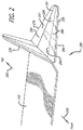
- FIG. 2 is an illustration of the disclosed system 200 for a protective finish for an airfoil, in accordance with at least one embodiment of the present disclosure.
- a main wing 210 of an aircraft (not shown) is shown to have two winglets, an upper winglet 220 and a lower winglet 230.
- arrow 240 is pointing towards the location of the nose of the aircraft
- arrow 250 is pointing towards the location of the tail of the aircraft.
- the disclosed system 200 is illustrated to be employed by the lower winglet 230; although it should be understood that the system 200 can be used with any suitable airfoil, such as a wiglet, a raked wing tip, and/or a wing. However, it should be noted that in various embodiments, both winglets 220, 230 or only one winglet 220, 230 (especially for the case of a main wing that only employs one winglet) may employ this disclosed system 200.
- the lower winglet 230 which employs the disclosed system 200, is shown to have a leading edge 260 and a trailing edge 270.
- the lower winglet 230 also has a front spar 280, a mid spar 285, and a rear spar 290.
- a sheath 295 is applied to the surface of the lower winglet 230.
- the sheath 295 is applied such that the sheath 295 wraps around the surface of the lower winglet 230 from the leading edge 260 of the lower winglet 230 towards the trailing edge 270 of the lower winglet 230, and such that the sheath 295 covers approximately 50 to approximately 70 percent of the chord length 297 of the lower winglet 230.
- the sheath 295 covers approximately two-thirds (2/3) of the chord length 297 of the lower winglet 230.
- the sheath 295 may be manufactured from at least one polymer, such as a polyurethane and/or a floropolymer.
- a polyurethane protective tape e.g., at least one large sheet of tape
- the sheath 295 is manufactured such that it is contoured corresponding to the shape of the lower winglet 230.
- one side of the sheath 295 is manufactured to have an adhesive.
- the adhesive side of the sheath 295 is placed in contact with the surface of the lower winglet 230 such that the sheath 295 adheres to the surface of lower winglet 230.
- the sheath 295 is significantly transparent.
- the customer livery may be printed on the side of the sheath 295 that is in contact with the surface of the lower winglet 230 such that the customer livery shows through on the opposite side of the sheath 295. Since the customer livery is printed on the underside of the sheath 295 and not the external side of the sheath 295, the layers of paint of the customer livery are covered by the sheath 295 and, thus, the paint layers will not cause a disruption to the laminar flow across the lower winglet 230.
- the customer livery may be painted directly onto the surface of the lower winglet 230, and then the sheath 295 may be placed on top of the surface of the lower winglet 230, thereby allowing the paint of the customer livery to show through the significantly transparent sheath 295. Since the customer livery is printed on the lower winglet 230, which is covered by the sheath 295, the layers of paint of the customer livery are covered by the sheath 295 and, thus, the paint layers will not cause a disruption to the laminar flow across the lower winglet 230.
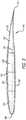
- FIG. 3 is a cross-sectional view of the lower winglet 230 of FIG. 2 , in accordance with at least one embodiment of the present disclosure.
- the lower winglet 230 is shown to have a leading edge 260 and a trailing edge 270.
- the chord 297 of the lower winglet 230 stretches from the leading edge 260 to the trailing edge 270.
- the lower winglet is shown to contain four cells: a first cell 310, a second cell 320, a third cell 330, and a fourth cell 340.
- the sheath 295 is shown to be applied to the surface of the lower winglet 230 such that the sheath 295 wraps around the surface of the lower winglet 230 from the leading edge 260 of the lower winglet 230 towards the trailing edge 270 of the lower winglet 230, and such that the sheath 295 covers approximately 50 to approximately 70 percent of the chord length 297 of the lower winglet 230.
Landscapes
- Engineering & Computer Science (AREA)
- Aviation & Aerospace Engineering (AREA)
- Mechanical Engineering (AREA)
- Turbine Rotor Nozzle Sealing (AREA)
- Structures Of Non-Positive Displacement Pumps (AREA)
- Application Of Or Painting With Fluid Materials (AREA)
- Catching Or Destruction (AREA)
Applications Claiming Priority (2)
| Application Number | Priority Date | Filing Date | Title |
|---|---|---|---|
| US13/887,211 US9845162B2 (en) | 2013-05-03 | 2013-05-03 | Protective finish for wing tip devices |
| EP14163491.5A EP2799330B1 (fr) | 2013-05-03 | 2014-04-04 | Finition protectrice pour dispositifs d'extrémité d'aile |
Related Parent Applications (2)
| Application Number | Title | Priority Date | Filing Date |
|---|---|---|---|
| EP14163491.5A Division EP2799330B1 (fr) | 2013-05-03 | 2014-04-04 | Finition protectrice pour dispositifs d'extrémité d'aile |
| EP14163491.5A Division-Into EP2799330B1 (fr) | 2013-05-03 | 2014-04-04 | Finition protectrice pour dispositifs d'extrémité d'aile |
Publications (2)
| Publication Number | Publication Date |
|---|---|
| EP3366572A1 true EP3366572A1 (fr) | 2018-08-29 |
| EP3366572B1 EP3366572B1 (fr) | 2020-07-08 |
Family
ID=50434079
Family Applications (2)
| Application Number | Title | Priority Date | Filing Date |
|---|---|---|---|
| EP14163491.5A Active EP2799330B1 (fr) | 2013-05-03 | 2014-04-04 | Finition protectrice pour dispositifs d'extrémité d'aile |
| EP18167097.7A Active EP3366572B1 (fr) | 2013-05-03 | 2014-04-04 | Finition protectrice pour dispositifs d'extrémité d'aile |
Family Applications Before (1)
| Application Number | Title | Priority Date | Filing Date |
|---|---|---|---|
| EP14163491.5A Active EP2799330B1 (fr) | 2013-05-03 | 2014-04-04 | Finition protectrice pour dispositifs d'extrémité d'aile |
Country Status (5)
| Country | Link |
|---|---|
| US (1) | US9845162B2 (fr) |
| EP (2) | EP2799330B1 (fr) |
| CN (1) | CN104129496B (fr) |
| BR (1) | BR102014010558B1 (fr) |
| CA (1) | CA2846709C (fr) |
Families Citing this family (13)
| Publication number | Priority date | Publication date | Assignee | Title |
|---|---|---|---|---|
| US9302766B2 (en) * | 2008-06-20 | 2016-04-05 | Aviation Partners, Inc. | Split blended winglet |
| DK2303685T3 (en) | 2008-06-20 | 2016-01-18 | Aviat Partners Inc | KRUM wingtip |
| CN103717490B (zh) * | 2011-06-09 | 2016-08-17 | 航空伙伴股份有限公司 | 螺旋形机翼末梢以及飞行器 |
| KR102457401B1 (ko) | 2013-08-07 | 2022-10-21 | 스트리커 코포레이션 | 초음파 핸드피스를 이 핸드피스의 기계 임피던스의 함수로서 구동시키기 위한 시스템 및 방법 |
| US10059461B2 (en) * | 2014-10-17 | 2018-08-28 | Saf-T-Glo Limited | Aircraft marking system |
| EP3269635A1 (fr) * | 2016-07-12 | 2018-01-17 | The Aircraft Performance Company UG | Aile d'avion |
| US10682840B2 (en) | 2017-06-01 | 2020-06-16 | The Boeing Company | Methods and systems for inkjet printing on co-curable paint film |
| ES2905192T3 (es) * | 2018-01-15 | 2022-04-07 | The Aircraft Performance Company Gmbh | Ala de avión |
| CN109551088A (zh) * | 2018-10-12 | 2019-04-02 | 江西昌河航空工业有限公司 | 一种用于翼尖罩焊接成形的工装 |
| US11952512B2 (en) | 2020-05-08 | 2024-04-09 | The Boeing Company | Chemical process for stripping surfaces |
| GB2615311A (en) * | 2022-01-31 | 2023-08-09 | Airbus Operations Ltd | Aircraft wing with movable wing tip device |
| GB2616252A (en) * | 2022-01-31 | 2023-09-06 | Airbus Operations Ltd | Aircraft with movable wing tip device |
| GB2628523B (en) * | 2022-11-16 | 2025-07-09 | Airbus Operations Ltd | Aircraft wing |
Citations (6)
| Publication number | Priority date | Publication date | Assignee | Title |
|---|---|---|---|---|
| GB662110A (en) * | 1949-07-11 | 1951-11-28 | Dehavilland Aircraft | Improvements in aircraft propeller and rotor blades |
| US2946541A (en) * | 1955-04-11 | 1960-07-26 | John R Boyd | Airfoil fluid flow control system |
| GB2461133A (en) * | 2008-06-27 | 2009-12-30 | George Valentino Constantinou | Erosion-protecting devices for aircraft |
| EP2348192A2 (fr) * | 2010-01-26 | 2011-07-27 | United Technologies Corporation | Gaine d'aube de soufflante |
| US20120156049A1 (en) * | 2005-12-14 | 2012-06-21 | Hong Shek C | Method and coating for protecting and repairing an airfoil surface |
| GB2490425A (en) * | 2011-04-28 | 2012-10-31 | Hamilton Sundstrand Corp | Interlocking blade sheath |
Family Cites Families (13)
| Publication number | Priority date | Publication date | Assignee | Title |
|---|---|---|---|---|
| US3616140A (en) * | 1968-05-17 | 1971-10-26 | Brunswick Corp | Rain erosion resistant material for airborne vehicle |
| US4594761A (en) * | 1984-02-13 | 1986-06-17 | General Electric Company | Method of fabricating hollow composite airfoils |
| FR2616409B1 (fr) * | 1987-06-09 | 1989-09-15 | Aerospatiale | Pale en materiaux composites et son procede de fabrication |
| DE3826378A1 (de) * | 1988-08-03 | 1990-02-08 | Mtu Muenchen Gmbh | Fasertechnische propellerschaufeln |
| US5486096A (en) * | 1994-06-30 | 1996-01-23 | United Technologies Corporation | Erosion resistant surface protection |
| US6516652B1 (en) * | 1999-06-08 | 2003-02-11 | Cortana Corporation | Design of viscoelastic coatings to reduce turbulent friction drag |
| US6290119B1 (en) * | 1999-11-08 | 2001-09-18 | Sonoco Development Inc. | Composite container having film label ply and method for manufacturing same |
| US8096508B2 (en) * | 2007-08-10 | 2012-01-17 | 3M Innovative Properties Company | Erosion resistant films for use on heated aerodynamic surfaces |
| US20110001016A1 (en) * | 2007-12-18 | 2011-01-06 | Robert Stewart Skillen | Telescoping and sweeping wing that is reconfigurable during flight |
| US8870124B2 (en) * | 2009-07-10 | 2014-10-28 | Peter Ireland | Application of elastomeric vortex generators |
| GB2483672B (en) * | 2010-09-15 | 2017-01-18 | Ge Aviat Systems Ltd | Propeller blades having icephobic coating |
| CN202320773U (zh) * | 2011-09-29 | 2012-07-11 | 西北工业大学 | 一种抗鸟撞飞机尾翼 |
| CN102582825B (zh) * | 2012-02-14 | 2013-12-25 | 西北工业大学 | 一种用于飞机机翼表面的密封机构 |
-
2013
- 2013-05-03 US US13/887,211 patent/US9845162B2/en active Active
-
2014
- 2014-03-14 CA CA2846709A patent/CA2846709C/fr active Active
- 2014-04-04 EP EP14163491.5A patent/EP2799330B1/fr active Active
- 2014-04-04 EP EP18167097.7A patent/EP3366572B1/fr active Active
- 2014-04-30 BR BR102014010558-1A patent/BR102014010558B1/pt active IP Right Grant
- 2014-05-04 CN CN201410184102.3A patent/CN104129496B/zh active Active
Patent Citations (6)
| Publication number | Priority date | Publication date | Assignee | Title |
|---|---|---|---|---|
| GB662110A (en) * | 1949-07-11 | 1951-11-28 | Dehavilland Aircraft | Improvements in aircraft propeller and rotor blades |
| US2946541A (en) * | 1955-04-11 | 1960-07-26 | John R Boyd | Airfoil fluid flow control system |
| US20120156049A1 (en) * | 2005-12-14 | 2012-06-21 | Hong Shek C | Method and coating for protecting and repairing an airfoil surface |
| GB2461133A (en) * | 2008-06-27 | 2009-12-30 | George Valentino Constantinou | Erosion-protecting devices for aircraft |
| EP2348192A2 (fr) * | 2010-01-26 | 2011-07-27 | United Technologies Corporation | Gaine d'aube de soufflante |
| GB2490425A (en) * | 2011-04-28 | 2012-10-31 | Hamilton Sundstrand Corp | Interlocking blade sheath |
Also Published As
| Publication number | Publication date |
|---|---|
| EP2799330A2 (fr) | 2014-11-05 |
| EP2799330A3 (fr) | 2014-12-17 |
| US20140328694A1 (en) | 2014-11-06 |
| CA2846709C (fr) | 2017-05-30 |
| CN104129496A (zh) | 2014-11-05 |
| EP2799330B1 (fr) | 2018-06-06 |
| CA2846709A1 (fr) | 2014-11-03 |
| BR102014010558A2 (pt) | 2015-01-20 |
| EP3366572B1 (fr) | 2020-07-08 |
| BR102014010558B1 (pt) | 2021-11-16 |
| US9845162B2 (en) | 2017-12-19 |
| CN104129496B (zh) | 2021-08-10 |
Similar Documents
| Publication | Publication Date | Title |
|---|---|---|
| EP2799330B1 (fr) | Finition protectrice pour dispositifs d'extrémité d'aile | |
| US7980515B2 (en) | Aircraft wing modification and related methods | |
| US11738857B2 (en) | Wing tip device | |
| CN215944856U (zh) | 一种固定翼察打一体无人机模型 | |
| EP1371550B1 (fr) | Bord de fuite d'un profil à écoulement laminaire | |
| US10629757B2 (en) | Laminar airfoil and the assembly and mounting of solar cell arrays on such airfoils | |
| CN208559739U (zh) | 一种翼尖预埋放电刷结构 | |
| US12528600B2 (en) | Methods and apparatus to repair composite airfoil structures | |
| Jacobs et al. | Effect of winglets on a first-generation jet transport wing. 1: Longitudinal aerodynamic characteristics of a semispan model at subsonic speeds | |
| RU2255023C1 (ru) | Способ торможения летательного аппарата с двухкилевым вертикальным оперением (варианты) | |
| CN211167372U (zh) | 一种飞机驾驶舱以及挡风玻璃结构 | |
| CN211391662U (zh) | 一种舵面固定装置 | |
| US11214351B2 (en) | Wing, aircraft, and method for delaying wing stall of an aircraft | |
| Stephens | Declassified April 15, 1958 | |
| Stephens | The Effect of External Stiffening Ribs on the Rolling Power of Ailerons on a Swept Wing | |
| Anderson et al. | FLIGHT MEASUREMENTS OF THE LOW-SPEED CHARACTERISTICS | |
| Mavriplis | COMPARISON OF PREDICTION, WIND TUNNEL AND FLIGHT TEST DATA FOR THE CANADAIR CHALLENCER TURBOFAN AIRCRAFT | |
| Grimaud et al. | Effects of Twist and Camber and Thickness on the Aerodynamic Characteristics of a 75 Deg Swept Arrow Wing at a Mach Number of 2.91 | |
| Keener | Professional Measurements Obtained in Flight at Transonic Speeds for a Conically Cambered Delta Wing | |
| Booker | AEROELASTIC TAILORING FOR CONTROL AND PERFORMANCE-ARE REQUIREMENTS COMPATIBLE? | |
| White | Wind-tunnel investigation of effects of wing-leading-edge modifications on the high angle-of-attack characteristics of a t-tail low-wing general-aviation aircraft | |
| HAVING et al. | By Angelo Bandettini Ames Aeronautical Laboratory Moffett Field, Calif. | |
| FR2401061A1 (fr) | Fuselage aerodynamique | |
| Daley | Aerodynamic Characteristics of Several 6-percent-thick Airfoils at Angles of Attack from 0 to 20 Degrees at High Subsonic Speeds | |
| Johnson | Flight Investigation of the Aerodynamic Forces on a Wing-mounted External-store Installation on the Douglas D-558-II Research Airplane |
Legal Events
| Date | Code | Title | Description |
|---|---|---|---|
| PUAI | Public reference made under article 153(3) epc to a published international application that has entered the european phase |
Free format text: ORIGINAL CODE: 0009012 |
|
| STAA | Information on the status of an ep patent application or granted ep patent |
Free format text: STATUS: REQUEST FOR EXAMINATION WAS MADE |
|
| 17P | Request for examination filed |
Effective date: 20180412 |
|
| AC | Divisional application: reference to earlier application |
Ref document number: 2799330 Country of ref document: EP Kind code of ref document: P |
|
| AK | Designated contracting states |
Kind code of ref document: A1 Designated state(s): AL AT BE BG CH CY CZ DE DK EE ES FI FR GB GR HR HU IE IS IT LI LT LU LV MC MK MT NL NO PL PT RO RS SE SI SK SM TR |
|
| GRAP | Despatch of communication of intention to grant a patent |
Free format text: ORIGINAL CODE: EPIDOSNIGR1 |
|
| STAA | Information on the status of an ep patent application or granted ep patent |
Free format text: STATUS: GRANT OF PATENT IS INTENDED |
|
| INTG | Intention to grant announced |
Effective date: 20200117 |
|
| GRAS | Grant fee paid |
Free format text: ORIGINAL CODE: EPIDOSNIGR3 |
|
| GRAA | (expected) grant |
Free format text: ORIGINAL CODE: 0009210 |
|
| STAA | Information on the status of an ep patent application or granted ep patent |
Free format text: STATUS: THE PATENT HAS BEEN GRANTED |
|
| AC | Divisional application: reference to earlier application |
Ref document number: 2799330 Country of ref document: EP Kind code of ref document: P |
|
| AK | Designated contracting states |
Kind code of ref document: B1 Designated state(s): AL AT BE BG CH CY CZ DE DK EE ES FI FR GB GR HR HU IE IS IT LI LT LU LV MC MK MT NL NO PL PT RO RS SE SI SK SM TR |
|
| REG | Reference to a national code |
Ref country code: CH Ref legal event code: EP Ref country code: AT Ref legal event code: REF Ref document number: 1288190 Country of ref document: AT Kind code of ref document: T Effective date: 20200715 |
|
| REG | Reference to a national code |
Ref country code: DE Ref legal event code: R096 Ref document number: 602014067637 Country of ref document: DE |
|
| REG | Reference to a national code |
Ref country code: IE Ref legal event code: FG4D |
|
| REG | Reference to a national code |
Ref country code: LT Ref legal event code: MG4D |
|
| REG | Reference to a national code |
Ref country code: AT Ref legal event code: MK05 Ref document number: 1288190 Country of ref document: AT Kind code of ref document: T Effective date: 20200708 |
|
| REG | Reference to a national code |
Ref country code: NL Ref legal event code: MP Effective date: 20200708 |
|
| PG25 | Lapsed in a contracting state [announced via postgrant information from national office to epo] |
Ref country code: HR Free format text: LAPSE BECAUSE OF FAILURE TO SUBMIT A TRANSLATION OF THE DESCRIPTION OR TO PAY THE FEE WITHIN THE PRESCRIBED TIME-LIMIT Effective date: 20200708 Ref country code: PT Free format text: LAPSE BECAUSE OF FAILURE TO SUBMIT A TRANSLATION OF THE DESCRIPTION OR TO PAY THE FEE WITHIN THE PRESCRIBED TIME-LIMIT Effective date: 20201109 Ref country code: LT Free format text: LAPSE BECAUSE OF FAILURE TO SUBMIT A TRANSLATION OF THE DESCRIPTION OR TO PAY THE FEE WITHIN THE PRESCRIBED TIME-LIMIT Effective date: 20200708 Ref country code: FI Free format text: LAPSE BECAUSE OF FAILURE TO SUBMIT A TRANSLATION OF THE DESCRIPTION OR TO PAY THE FEE WITHIN THE PRESCRIBED TIME-LIMIT Effective date: 20200708 Ref country code: SE Free format text: LAPSE BECAUSE OF FAILURE TO SUBMIT A TRANSLATION OF THE DESCRIPTION OR TO PAY THE FEE WITHIN THE PRESCRIBED TIME-LIMIT Effective date: 20200708 Ref country code: ES Free format text: LAPSE BECAUSE OF FAILURE TO SUBMIT A TRANSLATION OF THE DESCRIPTION OR TO PAY THE FEE WITHIN THE PRESCRIBED TIME-LIMIT Effective date: 20200708 Ref country code: GR Free format text: LAPSE BECAUSE OF FAILURE TO SUBMIT A TRANSLATION OF THE DESCRIPTION OR TO PAY THE FEE WITHIN THE PRESCRIBED TIME-LIMIT Effective date: 20201009 Ref country code: BG Free format text: LAPSE BECAUSE OF FAILURE TO SUBMIT A TRANSLATION OF THE DESCRIPTION OR TO PAY THE FEE WITHIN THE PRESCRIBED TIME-LIMIT Effective date: 20201008 Ref country code: NO Free format text: LAPSE BECAUSE OF FAILURE TO SUBMIT A TRANSLATION OF THE DESCRIPTION OR TO PAY THE FEE WITHIN THE PRESCRIBED TIME-LIMIT Effective date: 20201008 Ref country code: AT Free format text: LAPSE BECAUSE OF FAILURE TO SUBMIT A TRANSLATION OF THE DESCRIPTION OR TO PAY THE FEE WITHIN THE PRESCRIBED TIME-LIMIT Effective date: 20200708 |
|
| PG25 | Lapsed in a contracting state [announced via postgrant information from national office to epo] |
Ref country code: RS Free format text: LAPSE BECAUSE OF FAILURE TO SUBMIT A TRANSLATION OF THE DESCRIPTION OR TO PAY THE FEE WITHIN THE PRESCRIBED TIME-LIMIT Effective date: 20200708 Ref country code: PL Free format text: LAPSE BECAUSE OF FAILURE TO SUBMIT A TRANSLATION OF THE DESCRIPTION OR TO PAY THE FEE WITHIN THE PRESCRIBED TIME-LIMIT Effective date: 20200708 Ref country code: LV Free format text: LAPSE BECAUSE OF FAILURE TO SUBMIT A TRANSLATION OF THE DESCRIPTION OR TO PAY THE FEE WITHIN THE PRESCRIBED TIME-LIMIT Effective date: 20200708 Ref country code: IS Free format text: LAPSE BECAUSE OF FAILURE TO SUBMIT A TRANSLATION OF THE DESCRIPTION OR TO PAY THE FEE WITHIN THE PRESCRIBED TIME-LIMIT Effective date: 20201108 |
|
| PG25 | Lapsed in a contracting state [announced via postgrant information from national office to epo] |
Ref country code: NL Free format text: LAPSE BECAUSE OF FAILURE TO SUBMIT A TRANSLATION OF THE DESCRIPTION OR TO PAY THE FEE WITHIN THE PRESCRIBED TIME-LIMIT Effective date: 20200708 |
|
| REG | Reference to a national code |
Ref country code: DE Ref legal event code: R097 Ref document number: 602014067637 Country of ref document: DE |
|
| PG25 | Lapsed in a contracting state [announced via postgrant information from national office to epo] |
Ref country code: IT Free format text: LAPSE BECAUSE OF FAILURE TO SUBMIT A TRANSLATION OF THE DESCRIPTION OR TO PAY THE FEE WITHIN THE PRESCRIBED TIME-LIMIT Effective date: 20200708 Ref country code: SM Free format text: LAPSE BECAUSE OF FAILURE TO SUBMIT A TRANSLATION OF THE DESCRIPTION OR TO PAY THE FEE WITHIN THE PRESCRIBED TIME-LIMIT Effective date: 20200708 Ref country code: RO Free format text: LAPSE BECAUSE OF FAILURE TO SUBMIT A TRANSLATION OF THE DESCRIPTION OR TO PAY THE FEE WITHIN THE PRESCRIBED TIME-LIMIT Effective date: 20200708 Ref country code: DK Free format text: LAPSE BECAUSE OF FAILURE TO SUBMIT A TRANSLATION OF THE DESCRIPTION OR TO PAY THE FEE WITHIN THE PRESCRIBED TIME-LIMIT Effective date: 20200708 Ref country code: CZ Free format text: LAPSE BECAUSE OF FAILURE TO SUBMIT A TRANSLATION OF THE DESCRIPTION OR TO PAY THE FEE WITHIN THE PRESCRIBED TIME-LIMIT Effective date: 20200708 Ref country code: EE Free format text: LAPSE BECAUSE OF FAILURE TO SUBMIT A TRANSLATION OF THE DESCRIPTION OR TO PAY THE FEE WITHIN THE PRESCRIBED TIME-LIMIT Effective date: 20200708 |
|
| PLBE | No opposition filed within time limit |
Free format text: ORIGINAL CODE: 0009261 |
|
| STAA | Information on the status of an ep patent application or granted ep patent |
Free format text: STATUS: NO OPPOSITION FILED WITHIN TIME LIMIT |
|
| PG25 | Lapsed in a contracting state [announced via postgrant information from national office to epo] |
Ref country code: AL Free format text: LAPSE BECAUSE OF FAILURE TO SUBMIT A TRANSLATION OF THE DESCRIPTION OR TO PAY THE FEE WITHIN THE PRESCRIBED TIME-LIMIT Effective date: 20200708 |
|
| 26N | No opposition filed |
Effective date: 20210409 |
|
| PG25 | Lapsed in a contracting state [announced via postgrant information from national office to epo] |
Ref country code: SK Free format text: LAPSE BECAUSE OF FAILURE TO SUBMIT A TRANSLATION OF THE DESCRIPTION OR TO PAY THE FEE WITHIN THE PRESCRIBED TIME-LIMIT Effective date: 20200708 |
|
| PG25 | Lapsed in a contracting state [announced via postgrant information from national office to epo] |
Ref country code: SI Free format text: LAPSE BECAUSE OF FAILURE TO SUBMIT A TRANSLATION OF THE DESCRIPTION OR TO PAY THE FEE WITHIN THE PRESCRIBED TIME-LIMIT Effective date: 20200708 |
|
| PG25 | Lapsed in a contracting state [announced via postgrant information from national office to epo] |
Ref country code: MC Free format text: LAPSE BECAUSE OF FAILURE TO SUBMIT A TRANSLATION OF THE DESCRIPTION OR TO PAY THE FEE WITHIN THE PRESCRIBED TIME-LIMIT Effective date: 20200708 |
|
| PG25 | Lapsed in a contracting state [announced via postgrant information from national office to epo] |
Ref country code: LU Free format text: LAPSE BECAUSE OF NON-PAYMENT OF DUE FEES Effective date: 20210404 |
|
| REG | Reference to a national code |
Ref country code: BE Ref legal event code: MM Effective date: 20210430 |
|
| PG25 | Lapsed in a contracting state [announced via postgrant information from national office to epo] |
Ref country code: LI Free format text: LAPSE BECAUSE OF NON-PAYMENT OF DUE FEES Effective date: 20210430 Ref country code: CH Free format text: LAPSE BECAUSE OF NON-PAYMENT OF DUE FEES Effective date: 20210430 |
|
| PG25 | Lapsed in a contracting state [announced via postgrant information from national office to epo] |
Ref country code: IE Free format text: LAPSE BECAUSE OF NON-PAYMENT OF DUE FEES Effective date: 20210404 |
|
| PG25 | Lapsed in a contracting state [announced via postgrant information from national office to epo] |
Ref country code: IS Free format text: LAPSE BECAUSE OF FAILURE TO SUBMIT A TRANSLATION OF THE DESCRIPTION OR TO PAY THE FEE WITHIN THE PRESCRIBED TIME-LIMIT Effective date: 20201108 |
|
| PG25 | Lapsed in a contracting state [announced via postgrant information from national office to epo] |
Ref country code: BE Free format text: LAPSE BECAUSE OF NON-PAYMENT OF DUE FEES Effective date: 20210430 |
|
| P01 | Opt-out of the competence of the unified patent court (upc) registered |
Effective date: 20230516 |
|
| PG25 | Lapsed in a contracting state [announced via postgrant information from national office to epo] |
Ref country code: CY Free format text: LAPSE BECAUSE OF FAILURE TO SUBMIT A TRANSLATION OF THE DESCRIPTION OR TO PAY THE FEE WITHIN THE PRESCRIBED TIME-LIMIT Effective date: 20200708 |
|
| PG25 | Lapsed in a contracting state [announced via postgrant information from national office to epo] |
Ref country code: HU Free format text: LAPSE BECAUSE OF FAILURE TO SUBMIT A TRANSLATION OF THE DESCRIPTION OR TO PAY THE FEE WITHIN THE PRESCRIBED TIME-LIMIT; INVALID AB INITIO Effective date: 20140404 |
|
| PG25 | Lapsed in a contracting state [announced via postgrant information from national office to epo] |
Ref country code: MK Free format text: LAPSE BECAUSE OF FAILURE TO SUBMIT A TRANSLATION OF THE DESCRIPTION OR TO PAY THE FEE WITHIN THE PRESCRIBED TIME-LIMIT Effective date: 20200708 |
|
| PG25 | Lapsed in a contracting state [announced via postgrant information from national office to epo] |
Ref country code: TR Free format text: LAPSE BECAUSE OF FAILURE TO SUBMIT A TRANSLATION OF THE DESCRIPTION OR TO PAY THE FEE WITHIN THE PRESCRIBED TIME-LIMIT Effective date: 20200708 |
|
| PG25 | Lapsed in a contracting state [announced via postgrant information from national office to epo] |
Ref country code: MT Free format text: LAPSE BECAUSE OF FAILURE TO SUBMIT A TRANSLATION OF THE DESCRIPTION OR TO PAY THE FEE WITHIN THE PRESCRIBED TIME-LIMIT Effective date: 20200708 |
|
| PGFP | Annual fee paid to national office [announced via postgrant information from national office to epo] |
Ref country code: DE Payment date: 20250429 Year of fee payment: 12 |
|
| PGFP | Annual fee paid to national office [announced via postgrant information from national office to epo] |
Ref country code: GB Payment date: 20250428 Year of fee payment: 12 |
|
| PGFP | Annual fee paid to national office [announced via postgrant information from national office to epo] |
Ref country code: FR Payment date: 20250425 Year of fee payment: 12 |