EP3366580B1 - Flugzeugfahrwerk und zugehörige verfahren - Google Patents
Flugzeugfahrwerk und zugehörige verfahren Download PDFInfo
- Publication number
- EP3366580B1 EP3366580B1 EP18158456.6A EP18158456A EP3366580B1 EP 3366580 B1 EP3366580 B1 EP 3366580B1 EP 18158456 A EP18158456 A EP 18158456A EP 3366580 B1 EP3366580 B1 EP 3366580B1
- Authority
- EP
- European Patent Office
- Prior art keywords
- strut assembly
- assembly
- tubular housing
- configuration
- strut
- Prior art date
- Legal status (The legal status is an assumption and is not a legal conclusion. Google has not performed a legal analysis and makes no representation as to the accuracy of the status listed.)
- Active
Links
Images





Classifications
-
- B—PERFORMING OPERATIONS; TRANSPORTING
- B64—AIRCRAFT; AVIATION; COSMONAUTICS
- B64C—AEROPLANES; HELICOPTERS
- B64C25/00—Alighting gear
- B64C25/02—Undercarriages
- B64C25/08—Undercarriages non-fixed, e.g. jettisonable
- B64C25/10—Undercarriages non-fixed, e.g. jettisonable retractable, foldable, or the like
-
- B—PERFORMING OPERATIONS; TRANSPORTING
- B64—AIRCRAFT; AVIATION; COSMONAUTICS
- B64C—AEROPLANES; HELICOPTERS
- B64C25/00—Alighting gear
- B64C25/02—Undercarriages
- B64C25/08—Undercarriages non-fixed, e.g. jettisonable
- B64C25/10—Undercarriages non-fixed, e.g. jettisonable retractable, foldable, or the like
- B64C25/18—Operating mechanisms
- B64C25/22—Operating mechanisms fluid
-
- B—PERFORMING OPERATIONS; TRANSPORTING
- B64—AIRCRAFT; AVIATION; COSMONAUTICS
- B64C—AEROPLANES; HELICOPTERS
- B64C25/00—Alighting gear
- B64C25/32—Alighting gear characterised by elements which contact the ground or similar surface
- B64C25/34—Alighting gear characterised by elements which contact the ground or similar surface wheeled type, e.g. multi-wheeled bogies
- B64C25/36—Arrangements or adaptations of wheels, tyres or axles in general
-
- B—PERFORMING OPERATIONS; TRANSPORTING
- B64—AIRCRAFT; AVIATION; COSMONAUTICS
- B64C—AEROPLANES; HELICOPTERS
- B64C25/00—Alighting gear
- B64C25/32—Alighting gear characterised by elements which contact the ground or similar surface
- B64C25/58—Arrangements or adaptations of shock-absorbers or springs
- B64C25/60—Oleo legs
-
- B—PERFORMING OPERATIONS; TRANSPORTING
- B64—AIRCRAFT; AVIATION; COSMONAUTICS
- B64C—AEROPLANES; HELICOPTERS
- B64C25/00—Alighting gear
- B64C25/001—Devices not provided for in the groups B64C25/02 - B64C25/68
- B64C2025/008—Comprising means for modifying their length, e.g. for kneeling, for jumping, or for leveling the aircraft
-
- B—PERFORMING OPERATIONS; TRANSPORTING
- B64—AIRCRAFT; AVIATION; COSMONAUTICS
- B64C—AEROPLANES; HELICOPTERS
- B64C25/00—Alighting gear
- B64C25/02—Undercarriages
- B64C25/08—Undercarriages non-fixed, e.g. jettisonable
- B64C25/10—Undercarriages non-fixed, e.g. jettisonable retractable, foldable, or the like
- B64C25/12—Undercarriages non-fixed, e.g. jettisonable retractable, foldable, or the like sideways
- B64C2025/125—Undercarriages non-fixed, e.g. jettisonable retractable, foldable, or the like sideways into the fuselage, e.g. main landing gear pivotally retracting into or extending out of the fuselage
Definitions
- Landing gear structures on aircraft generally employ an oleo strut shock absorber, in which a piston compresses a volume that includes both a compressible gas and a substantially incompressible liquid.
- the volume includes two chambers separated by an orifice through which the liquid flows, such that the overall structure provides both resilient shock absorption and dampening of the oscillation of the oleo strut shock absorber.
- such landing gear structures include a main fitting (e.g., an outer tube), a piston (e.g., an inner tube), and a sliding tube cylinder, thus involving three tubes/cylinders.
- a landing gear structure that includes an oleo strut shock absorber may be compressed into a retracted configuration for stowage in the wheel well during flight. However, achieving the retracted configuration may require compressing the compressible gas to an undesirably high pressure. Additionally, such landing gear structures tend to be heavy and complex, thus creating potential disadvantages from aircraft economy, maintenance, and manufacture standpoints.
- the disclosure provides a strut assembly for an aircraft landing gear structure as defined in independent claim 1.
- Embodiments of the strut assembly form the subject matter of dependent claims 2-8.
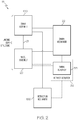
- strut assembly 100 has an extended pressure within pressure chamber 42 when strut assembly 100 is in the extended configuration and in the retracted configuration, and a compressed pressure within pressure chamber 42 when strut assembly 100 is in the compressed configuration.
- the compressed pressure is greater than the extended pressure, such as due to compression of a strut gas within pressure chamber 42.
- a retracted pressure within pressure chamber 42 when strut assembly 100 is in the retracted configuration is substantially equal to the extended pressure (e.g., there is substantially no compression of strut fluids or gases within pressure chamber 42 when strut assembly 100 is transitioned to the retracted configuration).
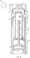
- Strut assembly 71 or aircraft landing gear structure 70 includes upper bulkhead 38 supported by upper tubular housing 26, and configured to be selectively and longitudinally translated with respect to upper tubular housing 26 between a lower position ( Figs 4 and 5 ) and an upper position ( Fig. 6 ).
- Upper bulkhead 38 is in the lower position when strut assembly 71 is in the compressed configuration and the extended configuration, and upper bulkhead 38 is in the upper position when strut assembly 71 is in the retracted configuration.
- Translation of upper bulkhead 38 to the upper position mechanically causes translation of lower tubular housing 28 to the retracted position, by virtue of a mechanical (e.g., physical) link between upper bulkhead 38 and lower tubular housing 28.
- shrink mechanism 23 includes upper bulkhead 38.
- a difference between extended length 74 and retracted length 76 may be in a range of 0-12.5 cm (0-5 inches), 12.5-25 cm (5-10 inches), 12.5-37.5 cm (5-15 inches), 25-62.5 cm (10-25 inches), 25-50 cm (10-20 inches), 25-37.5 cm (10-15 inches), 37.5-62.5 cm (15-25 inches), 37.5-50 cm (15-20 inches), and/or 50-62.5 cm (20-25 inches).
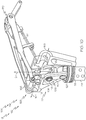
- Upper link 108 is pivotally coupled to a fixed structure of the aircraft, in some examples, such as via an upper pin 116.
- An apex pin 118 pivotally couples upper link 108 to lower link 110, and a lower pin 120 pivotally couples lower link 110 to strut assembly 71 (e.g., to upper bulkhead 38) in some examples.
- upper link 108 and lower link 110 may be coupled via other mechanisms, and/or locking link assembly 106 may be coupled to upper bulkhead 38 via other mechanisms. Additionally or alternatively, locking link assembly 106 may include additional links, connections, and/or components.
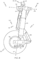
- pivot angle 60 is acute when strut assembly 71 is in the compressed configuration, and obtuse when strut assembly 71 is in the extended configuration.
- This is not meant to be limiting as to the arrangement between truck beam 34 and forward link 36 (e.g., all examples of strut assembly 100 or aircraft landing gear structure 18 need not have this arrangement), but rather is meant to describe an example of forward link 36 and truck beam 34 pivoting with respect to one another as strut assembly 71 transitions between configurations.
Landscapes
- Engineering & Computer Science (AREA)
- Mechanical Engineering (AREA)
- Aviation & Aerospace Engineering (AREA)
- Fluid-Damping Devices (AREA)
- Transmission Devices (AREA)
- General Details Of Gearings (AREA)
- Manipulator (AREA)
Claims (15)
- Federbeinanordnung (71, 100, 154) für eine Flugzeugfahrwerkstruktur (18), wobei die Federbeinanordnung (71, 100, 154) so ausgelegt ist, dass sie zwischen einer komprimierten Konfiguration, in der die Federbeinanordnung (71, 100, 154) eine komprimierte Länge (72) aufweist, wenn die Federbeinanordnung (71, 100, 154) von einem Flugzeug beschwert wird, einer ausgefahrenen Konfiguration, in der die Federbeinanordnung (71, 100, 154) eine ausgefahrene Länge (74) aufweist, wenn die Federbeinanordnung (71, 100, 154) nicht von dem Flugzeug beschwert wird, und einer eingefahrenen Konfiguration zum Verstauen der Flugzeugfahrwerkstruktur (18) innerhalb des Flugzeugs, bei der die Federbeinanordnung (71, 100, 154) eine eingefahrene Länge (76) aufweist, übergeht, wobei die komprimierte Länge (72) und die eingefahrene Länge (76) kleiner sind als die ausgefahrene Länge (74), wobei die komprimierte Länge (72), die eingefahrene Länge (76) und die ausgefahrene Länge (74) entlang einer Längsachse (24) der Federbeinanordnung (71, 100, 154) definiert sind, und wobei die Federbeinanordnung (71, 100, 154) Folgendes umfasst:ein oberes rohrförmiges Gehäuse (26);eine obere Trennwand (38), die von dem oberen rohrförmigen Gehäuse (26) getragen wird und so ausgelegt ist, dass sie wahlweise und in Längsrichtung in Bezug auf das obere rohrförmige Gehäuse (26) zwischen einer unteren Position und einer oberen Position verschoben werden kann, wobei die obere Trennwand (38) sich in der unteren Position befindet, wenn sich die Federbeinanordnung (71, 100, 154) in der komprimierten Konfiguration befindet und wenn sich die Federbeinanordnung (71, 100, 154) in der ausgefahrenen Konfiguration befindet, und wobei die obere Trennwand (38) sich in der oberen Position befindet, wenn sich die Federbeinanordnung (71, 100, 154) in der eingefahrenen Konfiguration befindet;ein unteres röhrenförmiges Gehäuse (28), das betriebsmäßig mit dem oberen röhrenförmigen Gehäuse (26) verbunden ist und so ausgelegt ist, dass es in Längsrichtung relativ zu dem oberen röhrenförmigen Gehäuse (26) verschoben werden kann;eine untere Trennwand (40), die in Bezug auf das untere rohrförmige Gehäuse (28) befestigt ist und von diesem getragen wird, wobei das untere rohrförmige Gehäuse (28) so ausgelegt ist, dass es in Längsrichtung zwischen einer komprimierten Position, wenn die Federbeinanordnung (71, 100, 154) sich in der komprimierten Konfiguration befindet, und einer ausgefahrenen Position, wenn die Federbeinanordnung (71, 100, 154) sich in der ausgefahrenen Konfiguration befindet, verschoben werden kann, wobei das untere rohrförmige Gehäuse (28) weiterhin so ausgelegt ist, dass es wahlweise und in Längsrichtung in eine eingefahrene Position verschoben wird, wenn die Federbeinanordnung (71, 100, 154) sich in der eingefahrenen Konfiguration befindet, und wobei die Federbeinanordnung (71, 100, 154) derart ausgelegt ist, dass eine Verschiebung der oberen Trennwand (38) in die obere Position mechanisch eine Verschiebung des unteren rohrförmigen Gehäuses (28) in die eingefahrene Position bewirkt; undeine Verriegelungsverbindungsstangenanordnung, die eine obere Verbindungsstange und eine untere Verbindungsstange umfasst, die schwenkbar miteinander verbunden sind, wobei die untere Verbindungsstange schwenkbar mit der oberen Verbindungsstange (38) gekoppelt ist, wobei die Verriegelungsverbindungsstangenanordnung derart ausgelegt ist, dass sie zwischen einer verlängerten Konfiguration und einer verkürzten Konfiguration übergeht,wobei die Federbeinanordnung (71, 100, 154) derart ausgelegt ist, dass die Verriegelungsverbindungsstangenstangenanordnung sich in der verlängerten Konfiguration befindet, wenn die Federbeinanordnung (71, 100, 154) sich in der komprimierten Konfiguration befindet und wenn die Federbeinanordnung (71, 100, 154) sich in der ausgefahrenen Konfiguration befindet, wobei die Federbeinanordnung (71, 100, 154) derart ausgelegt ist, dass die Verriegelungsverbindungsstangenanordnung sich in der verkürzten Konfiguration befindet, wenn die Federbeinanordnung (71, 100, 154) sich in der eingefahrenen Konfiguration befindet, und wobei die Federbeinanordnung (71, 100, 154) derart ausgelegt ist, dass das Übergehen der Verriegelungsverbindungsstangenanordnung aus der verlängerten Konfiguration in die verkürzte Konfiguration eine Längsverschiebung der oberen Trennwand (38) in die obere Position bewirkt;wobei die obere Verbindungsstange und die untere Verbindungsstange in der verlängerten Konfiguration in einer selbsthemmenden Position verriegelt sind, wobei die obere Verbindungsstange und die untere Verbindungsstange in der verkürzten Konfiguration nicht in einer selbsthemmenden Position gehalten werden, wobei die Verriegelungsverbindungsstangenanordnung derart ausgelegt ist, dass sie Kräften des Gewichts des Flugzeugs standhält, die über das untere rohrförmige Element, die untere Trennwand (40) und die obere Trennwand (38) auf die Verriegelungsverbindungsstangenanordnung übertragen werden, so dass sie in der verlängerten Konfiguration verbleibt, wenn die Federbeinanordnung (71, 100, 154) sich in der komprimierten Konfiguration befindet.
- Federbeinanordnung (71, 100, 154) nach Anspruch 1, die weiterhin ein drittes rohrförmiges Element umfasst, das sich in Längsrichtung von einem ersten Endbereich zu einem zweiten Endbereich erstreckt, wobei der erste Endbereich derart mit der oberen Trennwand (38) gekoppelt ist, dass das dritte rohrförmige Element im Wesentlichen in Bezug auf die obere Trennwand (38) fest ist, wobei der zweite Endbereich des dritten rohrförmigen Elements innerhalb des unteren rohrförmigen Gehäuses (28) angeordnet ist.
- Federbeinanordnung (71, 100, 154) nach Anspruch 2, die weiterhin einen Anschlag des dritten rohrförmigen Elements umfasst, der innerhalb des zweiten Endbereichs des dritten rohrförmigen Elements befestigt ist.
- Federbeinanordnung (71, 100, 154) nach Anspruch 3, wobei das untere rohrförmige Gehäuse (28) einen inneren Rohranschlag aufweist, der dazu ausgelegt ist, die Längsverschiebung des unteren rohrförmigen Gehäuses (28) in Bezug auf das obere rohrförmige Gehäuse (26) zu begrenzen, und wobei der Anschlag des dritten rohrförmigen Elements mit dem inneren Rohranschlag in Eingriff steht, wenn sich die Federbeinanordnung (71, 100, 154) in der ausgefahrenen Konfiguration befindet.
- Federbeinanordnung (71, 100, 154) nach Anspruch 3 oder 4, wobei die Federbeinanordnung (71, 100, 154) derart ausgelegt ist, dass eine Verschiebung der oberen Trennwand (38) in die obere Position mechanisch eine Längsverschiebung des dritten rohrförmigen Elements bewirkt, während der Anschlag des dritten rohrförmigen Elements den inneren rohrförmigen Anschlag des unteren rohrförmigen Gehäuses (28) berührt und eine Längsverschiebung desselben bewirkt, wodurch eine Verschiebung des unteren rohrförmigen Gehäuses (28) in die eingefahrene Position bewirkt wird.
- Federbeinanordnung (71, 100, 154) nach einem der Ansprüche 1 bis 5, wobei die Federbeinanordnung (71, 100, 154) weiterhin einen Schrumpfaktuator umfasst, der mit der Verriegelungsverbindungsstangenanordnung gekoppelt isst und dazu ausgelegt ist, die Verriegelungsverbindungsstangenanordnung wahlweise zwischen der verlängerten Konfiguration und der verkürzten Konfiguration übergehen zu lassen, und wobei der Schrumpfaktuator weiterhin dazu ausgelegt ist, die Flugzeugfahrwerkstruktur (18) in das Flugzeug einzufahren.
- Federbeinanordnung (71, 100, 154) nach einem der Ansprüche 1 bis 6, wobei eine Druckkammer zwischen der unteren Trennwand (40) und der oberen Trennwand (38) und innerhalb des oberen rohrförmigen Gehäuses (26) und des unteren rohrförmigen Gehäuses (28) definiert ist.
- Federbeinanordnung (71, 100, 154) nach Anspruch 7, wobei die obere Trennwand (38) eine dynamische Gasdichtung innerhalb des oberen rohrförmigen Gehäuses (26) bildet, wodurch im Wesentlichen verhindert wird, dass der Inhalt der Druckkammer an der oberen Trennwand (38) aus der Druckkammer entweicht;
wobei es sich bei der Federbeinanordnung (71, 100, 154) optional um eine Gas-Öl-Federbeinanordnung (71, 100, 154) handelt, die ein Federbeingas und ein Federbeinfluid in der Druckkammer aufweist, wobei die Federbeinanordnung (71, 100, 154) einen Ausfahrdruck innerhalb der Druckkammer aufweist, wenn die Federbeinanordnung (71, 100, 154) sich in der ausgefahrenen Konfiguration und in der eingefahrenen Konfiguration befindet, wobei die Federbeinanordnung (71, 100, 154) einen Komprimierungsdruck innerhalb der Druckkammer aufweist, wenn die Federbeinanordnung (71, 100, 154) sich in der komprimierten Konfiguration befindet, wobei der Komprimierungsdruck größer als der Ausfahrdruck ist, wobei die Druckkammer ein erstes Innenvolumen aufweist, wenn die Federbeinanordnung (71, 100, 154) sich in der ausgefahrenen Konfiguration und in der eingefahrenen Konfiguration befindet, wobei die Druckkammer ein zweites Innenvolumen aufweist, wenn die Federbeinanordnung (71, 100, 154) sich in der komprimierten Konfiguration befindet, und wobei das erste Innenvolumen aufgrund der Kompression des Federbeingases größer als das zweite Innenvolumen ist. - Flugzeugfahrwerksstruktur (18), die Folgendes umfasst:die Federbeinanordnung (71, 100, 154) nach einem der Ansprüche 1 bis 8; undwenigstens eine Radanordnung, die mit dem unteren rohrförmigen Gehäuse (28) der Federbeinanordnung (71, 100, 154) betriebsmäßig gekoppelt ist.
- Flugzeug, das Folgendes umfasst:einen Rumpf;eine Tragflächenanordnung, die mit dem Rumpf betriebsmäßig gekoppelt ist, wobei einer oder mehrere von Rumpf und Tragflächenanordnung einen oder mehrere Radkästen, Fahrwerksschächte oder Radschächte definieren; undeine oder mehrere Federbeinanordnungen (71, 100, 154) nach einem der Ansprüche 1 bis 8, die betriebsmäßig mit einer oder mehreren von Rumpf und Tragflächenanordnung gekoppelt ist bzw. sind, wobei die eine oder mehreren Federbeinanordnungen (71, 100, 154) derart ausgelegt sind, dass sie während des Fluges in dem einen oder den mehreren Radkästen, Fahrwerksschächten oder Radschächten gelagert werden.
- Verfahren zum Einfahren einer Federbeinanordnung (71, 100, 154) zum Verstauen eines Flugzeugfahrwerks in einem Flugzeug, wobei das Verfahren Folgendes umfasst:Bereitstellen der Federbeinanordnung (71, 100, 154) nach einem der Ansprüche 1 bis 8;Schrumpfen der Federbeinanordnung (71, 100, 154) durch Längsverschieben der oberen Trennwand (38) innerhalb des oberen rohrförmigen Gehäuses (26) von der unteren Position in die obere Position, wobei die Längsverschiebung der oberen Trennwand (38) mechanisch eine Verschiebung des unteren rohrförmigen Gehäuses (28) in Bezug auf das obere rohrförmige Gehäuse (26) bewirkt, wobei die Längsverschiebung der oberen Trennwand (38) in die obere Position bewirkt, dass die Federbeinanordnung (71, 100, 154) in die eingefahrene Konfiguration übergeht; undEinfahren der Strebenanordnung (71, 100, 154) in einen Radkasten des Flugzeugs;wobei das Verfahren weiterhin Folgendes umfasst:a) Verriegeln einer Verriegelungsverbindungsstangenanordnung in einer verlängerten Konfiguration, wodurch die obere Trennwand (38) in der unteren Position gehalten wird; undb) Entriegeln der Verriegelungsverbindungsstangenanordnung und Übergehen der Verriegelungsverbindungsstangenanordnung in eine verkürzte Konfiguration, wodurch die obere Trennwand (38) in Längsrichtung in die obere Position verschoben wird.
- Verfahren nach Anspruch 11, wobei das Einfahren der Federbeinanordnung (71, 100, 154) durch einen Rückzugsaktuator durchgeführt wird, und wobei der Rückzugsaktuator einen Schrumpfmechanismus betätigt, der das Schrumpfen der Federbeinanordnung (71, 100, 154) durchführt.
- Verfahren nach Anspruch 11 oder 12, wobei die Federbeinanordnung (71, 100, 154) weiterhin Folgendes umfasst:ein drittes rohrförmiges Element, das sich in Längsrichtung von einem ersten Endbereich zu einem zweiten Endbereich erstreckt, wobei der erste Endbereich derart mit der oberen Trennwand (38) gekoppelt ist, dass das dritte rohrförmige Element im Wesentlichen in Bezug auf die obere Trennwand (38) fest ist, wobei der zweite Endbereich des dritten rohrförmigen Elements innerhalb des unteren rohrförmigen Gehäuses (28) angeordnet ist;einen Anschlag des dritten rohrförmigen Elements, der innerhalb des zweiten Endbereichs des dritten rohrförmigen Elements befestigt ist; undeinnen inneren Rohranschlag innerhalb des unteren rohrförmigen Gehäusen (28), wobei der innere Rohranschlag dazu ausgelegt ist, die Längsverschiebung des unteren rohrförmigen Gehäuses (28) in Bezug auf das obere rohrförmige Gehäuse (26) zu begrenzen, und wobei der Anschlag des dritten rohrförmigen Elements mit dem inneren Rohranschlag in Eingriff steht, wenn sich die Federbeinanordnung (71, 100, 154) in der ausgefahrenen Konfiguration befindet.
- Verfahren nach Anspruch 13, wobei das Schrumpfen der Federbeinanordnung (71, 100, 154) eine Verschiebung der oberen Trennwand (38) in die obere Position umfasst, und dadurch mechanisch eine Längsverschiebung des dritten rohrförmigen Elements und des Anschlags des dritten rohrförmigen Elements bewirkt, während der Anschlag des dritten rohrförmigen Elements den inneren rohrförmigen Anschlag des unteren rohrförmigen Gehäuses (28) berührt und eine Längsverschiebung desselben bewirkt, wodurch eine Verschiebung des unteren rohrförmigen Gehäuses (28) in die eingefahrene Position bewirkt wird.
- Verfahren nach einem der Ansprüche 11 bis 14, wobei das Einfahren der Federbeinanordnung (71, 100, 154) in den Radkasten das Einfahren der Federbeinanordnung (71, 100, 154) und einer betriebsmäßig mit der Federbeinanordnung (71, 100, 154) gekoppelten Radanordnung umfasst.
Applications Claiming Priority (1)
| Application Number | Priority Date | Filing Date | Title |
|---|---|---|---|
| US15/445,836 US10669017B2 (en) | 2017-02-28 | 2017-02-28 | Aircraft landing gear, aircraft, and related methods |
Publications (2)
| Publication Number | Publication Date |
|---|---|
| EP3366580A1 EP3366580A1 (de) | 2018-08-29 |
| EP3366580B1 true EP3366580B1 (de) | 2020-09-30 |
Family
ID=61274206
Family Applications (1)
| Application Number | Title | Priority Date | Filing Date |
|---|---|---|---|
| EP18158456.6A Active EP3366580B1 (de) | 2017-02-28 | 2018-02-23 | Flugzeugfahrwerk und zugehörige verfahren |
Country Status (9)
| Country | Link |
|---|---|
| US (1) | US10669017B2 (de) |
| EP (1) | EP3366580B1 (de) |
| JP (1) | JP7053300B2 (de) |
| KR (1) | KR102481424B1 (de) |
| CN (1) | CN108502142B (de) |
| AU (1) | AU2018200465B2 (de) |
| BR (1) | BR102018003345B1 (de) |
| CA (1) | CA2995182C (de) |
| RU (1) | RU2745415C2 (de) |
Cited By (1)
| Publication number | Priority date | Publication date | Assignee | Title |
|---|---|---|---|---|
| EP3366579B1 (de) * | 2017-02-28 | 2024-10-30 | The Boeing Company | Flugzeugfahrwerk und zugehöriges verfahren |
Families Citing this family (8)
| Publication number | Priority date | Publication date | Assignee | Title |
|---|---|---|---|---|
| US10562614B2 (en) | 2016-09-21 | 2020-02-18 | The Boeing Company | Aircraft landing gear, aircraft, and related methods |
| US10597146B2 (en) * | 2017-02-28 | 2020-03-24 | The Boeing Company | Aircraft landing gear having a lever assembly, aircraft including the same, and related methods |
| US10669017B2 (en) | 2017-02-28 | 2020-06-02 | The Boeing Company | Aircraft landing gear, aircraft, and related methods |
| US10981646B2 (en) * | 2018-07-30 | 2021-04-20 | The Boeing Company | Landing gear shrink link mechanism |
| GB2586824A (en) * | 2019-09-04 | 2021-03-10 | Airbus Operations Ltd | Landing gear assembly |
| JP7256761B2 (ja) * | 2020-01-09 | 2023-04-12 | 川崎重工業株式会社 | 昇降システム |
| US12054282B2 (en) * | 2022-05-23 | 2024-08-06 | Safran Landing Systems Canada Inc. | Landing gear load detection system |
| KR20240084326A (ko) * | 2022-12-06 | 2024-06-13 | 현대자동차주식회사 | 랜딩 기어 시스템 |
Family Cites Families (36)
| Publication number | Priority date | Publication date | Assignee | Title |
|---|---|---|---|---|
| US2174315A (en) | 1936-03-16 | 1939-09-26 | Dowty George Herbert | Aircraft undercarriage |
| US2467015A (en) | 1944-11-03 | 1949-04-12 | Curtiss Wright Corp | Retracting mechanism |
| US2621004A (en) * | 1950-06-16 | 1952-12-09 | Electrol Inc | Retractable landing gear |
| US2754072A (en) | 1952-09-23 | 1956-07-10 | Roeing Airplane Company | Aircraft landing gear |
| US2892626A (en) | 1955-08-17 | 1959-06-30 | Cleveland Pneumatic Ind Inc | Landing gear construction |
| US2868482A (en) | 1955-10-18 | 1959-01-13 | Cleveland Pneumatic Ind Inc | Retractable landing gear |
| US3195840A (en) * | 1963-10-10 | 1965-07-20 | Bendix Corp | Aircraft landing gear |
| US3580531A (en) | 1968-07-19 | 1971-05-25 | Ver Flugtechnische Werke | Retractable main carriage for vertically starting airplanes and airplanes starting on a short runway |
| US4004762A (en) | 1974-06-06 | 1977-01-25 | Automotive Products Company Limited | Aircraft undercarriage with ride control means |
| FR2461852A1 (fr) | 1979-07-17 | 1981-02-06 | Messier Hispano Sa | Perfectionnements aux amortisseurs et amortisseurs-verins notamment pour trains d'atterrissage d'aerodyne |
| FR2547271B1 (fr) | 1983-06-08 | 1985-08-23 | Messier Hispano Sa | Atterrisseur du type a balancier |
| FR2598676B1 (fr) * | 1986-05-13 | 1988-07-29 | Messier Hispano Sa | Atterrisseur d'aeronef a poutre basculante et a encombrement reduit |
| JP2784574B2 (ja) * | 1988-03-30 | 1998-08-06 | 住友精密工業株式会社 | 航空機用緩衝装置 |
| US4907760A (en) | 1988-05-18 | 1990-03-13 | The Boeing Company | Contracting landing gear shock strut |
| FR2688467B1 (fr) * | 1992-03-11 | 1994-05-13 | Messier Bugatti | Atterrisseur relevable a raccourcissement de jambe. |
| FR2699886B1 (fr) * | 1992-12-28 | 1995-03-24 | Messier Bugatti | Atterrisseur relevable, notamment pour avion gros porteur. |
| US6182925B1 (en) | 1999-03-30 | 2001-02-06 | The Boeing Company | Semi-levered landing gear and auxiliary strut therefor |
| GB2428650B (en) | 2005-08-04 | 2011-01-12 | Messier Dowty Ltd | Landing gear |
| US8186620B2 (en) * | 2008-06-25 | 2012-05-29 | Goodrich Corporation | Adjustable landing gear system |
| US8973725B2 (en) | 2008-07-21 | 2015-03-10 | Goodrich Corporation | Shock strut with pressure relief |
| US8556209B2 (en) | 2008-10-22 | 2013-10-15 | Goodrich Corporation | Electric-powered transfer cylinder for landing gear system |
| FR2939099B1 (fr) * | 2008-12-02 | 2012-06-22 | Messier Dowty Sa | Dispositif electromecanique multifonctions pour atterrisseur |
| FR2939407B1 (fr) * | 2008-12-05 | 2011-02-11 | Messier Dowty Sa | Dispositif de raccourcissement d'un atterisseur d'aeronef |
| US8448900B2 (en) | 2010-03-24 | 2013-05-28 | The Boeing Company | Semi-levered landing gear and associated method |
| US9481452B2 (en) | 2010-11-22 | 2016-11-01 | The Boeing Company | Hydraulic actuator for semi levered landing gear |
| US8998133B2 (en) | 2011-04-01 | 2015-04-07 | The Boeing Company | Landing gear system |
| RU2539433C2 (ru) * | 2012-10-30 | 2015-01-20 | Российская Федерация, от имени которой выступает Министерство промышленности и торговли Российской Федерации (Департамент авиационной промышленности Минпромторга России) | Убирающаяся опора шасси летательного аппарата |
| US9308989B2 (en) | 2013-01-16 | 2016-04-12 | Otto Aviation Group | Aircraft front landing gear and method of operating the same |
| US9321525B2 (en) | 2013-10-11 | 2016-04-26 | Goodrich Corporation | Shrink strut landing gear system, method, and apparatus |
| GB2528498A (en) | 2014-07-24 | 2016-01-27 | Airbus Operations Ltd | Aircraft landing gear |
| GB2529483A (en) * | 2014-08-22 | 2016-02-24 | Airbus Operations Ltd | A landing gear assembly |
| EP3263449B1 (de) | 2016-07-01 | 2018-08-29 | Safran Landing Systems UK Limited | Fahrwerk für ein flugzeug |
| US10597146B2 (en) | 2017-02-28 | 2020-03-24 | The Boeing Company | Aircraft landing gear having a lever assembly, aircraft including the same, and related methods |
| US10669017B2 (en) | 2017-02-28 | 2020-06-02 | The Boeing Company | Aircraft landing gear, aircraft, and related methods |
| US10766608B2 (en) | 2017-02-28 | 2020-09-08 | The Boeing Company | Aircraft landing gear having a retract actuator, aircraft including the same, and related methods |
| US10800516B2 (en) | 2017-06-02 | 2020-10-13 | The Boeing Company | Semi-levered shrink landing gear |
-
2017
- 2017-02-28 US US15/445,836 patent/US10669017B2/en active Active
-
2018
- 2018-01-19 AU AU2018200465A patent/AU2018200465B2/en active Active
- 2018-01-22 RU RU2018102302A patent/RU2745415C2/ru active
- 2018-02-01 CN CN201810104265.4A patent/CN108502142B/zh active Active
- 2018-02-14 CA CA2995182A patent/CA2995182C/en active Active
- 2018-02-16 JP JP2018025568A patent/JP7053300B2/ja active Active
- 2018-02-21 BR BR102018003345-0A patent/BR102018003345B1/pt active IP Right Grant
- 2018-02-23 EP EP18158456.6A patent/EP3366580B1/de active Active
- 2018-02-27 KR KR1020180024022A patent/KR102481424B1/ko active Active
Non-Patent Citations (1)
| Title |
|---|
| None * |
Cited By (1)
| Publication number | Priority date | Publication date | Assignee | Title |
|---|---|---|---|---|
| EP3366579B1 (de) * | 2017-02-28 | 2024-10-30 | The Boeing Company | Flugzeugfahrwerk und zugehöriges verfahren |
Also Published As
| Publication number | Publication date |
|---|---|
| US10669017B2 (en) | 2020-06-02 |
| JP7053300B2 (ja) | 2022-04-12 |
| RU2745415C2 (ru) | 2021-03-24 |
| RU2018102302A (ru) | 2019-07-23 |
| CA2995182C (en) | 2022-05-31 |
| CN108502142A (zh) | 2018-09-07 |
| CN108502142B (zh) | 2022-10-11 |
| BR102018003345A2 (pt) | 2018-10-30 |
| RU2018102302A3 (de) | 2021-01-21 |
| EP3366580A1 (de) | 2018-08-29 |
| JP2018172107A (ja) | 2018-11-08 |
| KR102481424B1 (ko) | 2022-12-23 |
| AU2018200465A1 (en) | 2018-09-13 |
| AU2018200465B2 (en) | 2022-08-25 |
| BR102018003345B1 (pt) | 2023-12-26 |
| US20180244371A1 (en) | 2018-08-30 |
| KR20180099554A (ko) | 2018-09-05 |
| CA2995182A1 (en) | 2018-08-28 |
Similar Documents
| Publication | Publication Date | Title |
|---|---|---|
| EP3366579B1 (de) | Flugzeugfahrwerk und zugehöriges verfahren | |
| US11407499B2 (en) | Aircraft landing gear having a lever assembly, aircraft including the same, and related methods | |
| EP3366580B1 (de) | Flugzeugfahrwerk und zugehörige verfahren | |
| EP2860102B1 (de) | Schrumpfstreben-Fahrwerksystem | |
| EP3409582B1 (de) | Halbgehebeltes schrumpffahrwerk | |
| US11427309B2 (en) | Hinged truck assembly for aircraft landing gear | |
| US20200115042A1 (en) | Aircraft landing gear, aircraft, and related methods |
Legal Events
| Date | Code | Title | Description |
|---|---|---|---|
| PUAI | Public reference made under article 153(3) epc to a published international application that has entered the european phase |
Free format text: ORIGINAL CODE: 0009012 |
|
| STAA | Information on the status of an ep patent application or granted ep patent |
Free format text: STATUS: REQUEST FOR EXAMINATION WAS MADE |
|
| 17P | Request for examination filed |
Effective date: 20180223 |
|
| AK | Designated contracting states |
Kind code of ref document: A1 Designated state(s): AL AT BE BG CH CY CZ DE DK EE ES FI FR GB GR HR HU IE IS IT LI LT LU LV MC MK MT NL NO PL PT RO RS SE SI SK SM TR |
|
| AX | Request for extension of the european patent |
Extension state: BA ME |
|
| GRAP | Despatch of communication of intention to grant a patent |
Free format text: ORIGINAL CODE: EPIDOSNIGR1 |
|
| STAA | Information on the status of an ep patent application or granted ep patent |
Free format text: STATUS: GRANT OF PATENT IS INTENDED |
|
| INTG | Intention to grant announced |
Effective date: 20191108 |
|
| RIN1 | Information on inventor provided before grant (corrected) |
Inventor name: MELLOR, MITCHELL LOREN RAY Inventor name: SIMPSON, MARK NICHOLAS Inventor name: COTTET, JUSTIN Inventor name: CUSWORTH, JAMES E. |
|
| GRAS | Grant fee paid |
Free format text: ORIGINAL CODE: EPIDOSNIGR3 |
|
| GRAJ | Information related to disapproval of communication of intention to grant by the applicant or resumption of examination proceedings by the epo deleted |
Free format text: ORIGINAL CODE: EPIDOSDIGR1 |
|
| GRAL | Information related to payment of fee for publishing/printing deleted |
Free format text: ORIGINAL CODE: EPIDOSDIGR3 |
|
| STAA | Information on the status of an ep patent application or granted ep patent |
Free format text: STATUS: REQUEST FOR EXAMINATION WAS MADE |
|
| GRAP | Despatch of communication of intention to grant a patent |
Free format text: ORIGINAL CODE: EPIDOSNIGR1 |
|
| STAA | Information on the status of an ep patent application or granted ep patent |
Free format text: STATUS: GRANT OF PATENT IS INTENDED |
|
| INTC | Intention to grant announced (deleted) | ||
| INTG | Intention to grant announced |
Effective date: 20200424 |
|
| GRAS | Grant fee paid |
Free format text: ORIGINAL CODE: EPIDOSNIGR3 |
|
| GRAA | (expected) grant |
Free format text: ORIGINAL CODE: 0009210 |
|
| STAA | Information on the status of an ep patent application or granted ep patent |
Free format text: STATUS: THE PATENT HAS BEEN GRANTED |
|
| AK | Designated contracting states |
Kind code of ref document: B1 Designated state(s): AL AT BE BG CH CY CZ DE DK EE ES FI FR GB GR HR HU IE IS IT LI LT LU LV MC MK MT NL NO PL PT RO RS SE SI SK SM TR |
|
| REG | Reference to a national code |
Ref country code: GB Ref legal event code: FG4D Ref country code: CH Ref legal event code: EP |
|
| REG | Reference to a national code |
Ref country code: AT Ref legal event code: REF Ref document number: 1318547 Country of ref document: AT Kind code of ref document: T Effective date: 20201015 |
|
| REG | Reference to a national code |
Ref country code: DE Ref legal event code: R096 Ref document number: 602018008176 Country of ref document: DE |
|
| REG | Reference to a national code |
Ref country code: IE Ref legal event code: FG4D |
|
| PG25 | Lapsed in a contracting state [announced via postgrant information from national office to epo] |
Ref country code: HR Free format text: LAPSE BECAUSE OF FAILURE TO SUBMIT A TRANSLATION OF THE DESCRIPTION OR TO PAY THE FEE WITHIN THE PRESCRIBED TIME-LIMIT Effective date: 20200930 Ref country code: BG Free format text: LAPSE BECAUSE OF FAILURE TO SUBMIT A TRANSLATION OF THE DESCRIPTION OR TO PAY THE FEE WITHIN THE PRESCRIBED TIME-LIMIT Effective date: 20201230 Ref country code: SE Free format text: LAPSE BECAUSE OF FAILURE TO SUBMIT A TRANSLATION OF THE DESCRIPTION OR TO PAY THE FEE WITHIN THE PRESCRIBED TIME-LIMIT Effective date: 20200930 Ref country code: NO Free format text: LAPSE BECAUSE OF FAILURE TO SUBMIT A TRANSLATION OF THE DESCRIPTION OR TO PAY THE FEE WITHIN THE PRESCRIBED TIME-LIMIT Effective date: 20201230 Ref country code: GR Free format text: LAPSE BECAUSE OF FAILURE TO SUBMIT A TRANSLATION OF THE DESCRIPTION OR TO PAY THE FEE WITHIN THE PRESCRIBED TIME-LIMIT Effective date: 20201231 Ref country code: FI Free format text: LAPSE BECAUSE OF FAILURE TO SUBMIT A TRANSLATION OF THE DESCRIPTION OR TO PAY THE FEE WITHIN THE PRESCRIBED TIME-LIMIT Effective date: 20200930 |
|
| REG | Reference to a national code |
Ref country code: AT Ref legal event code: MK05 Ref document number: 1318547 Country of ref document: AT Kind code of ref document: T Effective date: 20200930 |
|
| PG25 | Lapsed in a contracting state [announced via postgrant information from national office to epo] |
Ref country code: LV Free format text: LAPSE BECAUSE OF FAILURE TO SUBMIT A TRANSLATION OF THE DESCRIPTION OR TO PAY THE FEE WITHIN THE PRESCRIBED TIME-LIMIT Effective date: 20200930 Ref country code: RS Free format text: LAPSE BECAUSE OF FAILURE TO SUBMIT A TRANSLATION OF THE DESCRIPTION OR TO PAY THE FEE WITHIN THE PRESCRIBED TIME-LIMIT Effective date: 20200930 |
|
| REG | Reference to a national code |
Ref country code: NL Ref legal event code: MP Effective date: 20200930 |
|
| REG | Reference to a national code |
Ref country code: LT Ref legal event code: MG4D |
|
| PG25 | Lapsed in a contracting state [announced via postgrant information from national office to epo] |
Ref country code: EE Free format text: LAPSE BECAUSE OF FAILURE TO SUBMIT A TRANSLATION OF THE DESCRIPTION OR TO PAY THE FEE WITHIN THE PRESCRIBED TIME-LIMIT Effective date: 20200930 Ref country code: CZ Free format text: LAPSE BECAUSE OF FAILURE TO SUBMIT A TRANSLATION OF THE DESCRIPTION OR TO PAY THE FEE WITHIN THE PRESCRIBED TIME-LIMIT Effective date: 20200930 Ref country code: RO Free format text: LAPSE BECAUSE OF FAILURE TO SUBMIT A TRANSLATION OF THE DESCRIPTION OR TO PAY THE FEE WITHIN THE PRESCRIBED TIME-LIMIT Effective date: 20200930 Ref country code: PT Free format text: LAPSE BECAUSE OF FAILURE TO SUBMIT A TRANSLATION OF THE DESCRIPTION OR TO PAY THE FEE WITHIN THE PRESCRIBED TIME-LIMIT Effective date: 20210201 Ref country code: SM Free format text: LAPSE BECAUSE OF FAILURE TO SUBMIT A TRANSLATION OF THE DESCRIPTION OR TO PAY THE FEE WITHIN THE PRESCRIBED TIME-LIMIT Effective date: 20200930 Ref country code: LT Free format text: LAPSE BECAUSE OF FAILURE TO SUBMIT A TRANSLATION OF THE DESCRIPTION OR TO PAY THE FEE WITHIN THE PRESCRIBED TIME-LIMIT Effective date: 20200930 |
|
| PG25 | Lapsed in a contracting state [announced via postgrant information from national office to epo] |
Ref country code: IS Free format text: LAPSE BECAUSE OF FAILURE TO SUBMIT A TRANSLATION OF THE DESCRIPTION OR TO PAY THE FEE WITHIN THE PRESCRIBED TIME-LIMIT Effective date: 20210130 Ref country code: PL Free format text: LAPSE BECAUSE OF FAILURE TO SUBMIT A TRANSLATION OF THE DESCRIPTION OR TO PAY THE FEE WITHIN THE PRESCRIBED TIME-LIMIT Effective date: 20200930 Ref country code: ES Free format text: LAPSE BECAUSE OF FAILURE TO SUBMIT A TRANSLATION OF THE DESCRIPTION OR TO PAY THE FEE WITHIN THE PRESCRIBED TIME-LIMIT Effective date: 20200930 Ref country code: AT Free format text: LAPSE BECAUSE OF FAILURE TO SUBMIT A TRANSLATION OF THE DESCRIPTION OR TO PAY THE FEE WITHIN THE PRESCRIBED TIME-LIMIT Effective date: 20200930 Ref country code: AL Free format text: LAPSE BECAUSE OF FAILURE TO SUBMIT A TRANSLATION OF THE DESCRIPTION OR TO PAY THE FEE WITHIN THE PRESCRIBED TIME-LIMIT Effective date: 20200930 |
|
| PG25 | Lapsed in a contracting state [announced via postgrant information from national office to epo] |
Ref country code: NL Free format text: LAPSE BECAUSE OF FAILURE TO SUBMIT A TRANSLATION OF THE DESCRIPTION OR TO PAY THE FEE WITHIN THE PRESCRIBED TIME-LIMIT Effective date: 20200930 Ref country code: SK Free format text: LAPSE BECAUSE OF FAILURE TO SUBMIT A TRANSLATION OF THE DESCRIPTION OR TO PAY THE FEE WITHIN THE PRESCRIBED TIME-LIMIT Effective date: 20200930 |
|
| REG | Reference to a national code |
Ref country code: DE Ref legal event code: R097 Ref document number: 602018008176 Country of ref document: DE |
|
| PLBE | No opposition filed within time limit |
Free format text: ORIGINAL CODE: 0009261 |
|
| STAA | Information on the status of an ep patent application or granted ep patent |
Free format text: STATUS: NO OPPOSITION FILED WITHIN TIME LIMIT |
|
| PG25 | Lapsed in a contracting state [announced via postgrant information from national office to epo] |
Ref country code: DK Free format text: LAPSE BECAUSE OF FAILURE TO SUBMIT A TRANSLATION OF THE DESCRIPTION OR TO PAY THE FEE WITHIN THE PRESCRIBED TIME-LIMIT Effective date: 20200930 |
|
| 26N | No opposition filed |
Effective date: 20210701 |
|
| PG25 | Lapsed in a contracting state [announced via postgrant information from national office to epo] |
Ref country code: MC Free format text: LAPSE BECAUSE OF FAILURE TO SUBMIT A TRANSLATION OF THE DESCRIPTION OR TO PAY THE FEE WITHIN THE PRESCRIBED TIME-LIMIT Effective date: 20200930 |
|
| REG | Reference to a national code |
Ref country code: BE Ref legal event code: MM Effective date: 20210228 |
|
| PG25 | Lapsed in a contracting state [announced via postgrant information from national office to epo] |
Ref country code: CH Free format text: LAPSE BECAUSE OF NON-PAYMENT OF DUE FEES Effective date: 20210228 Ref country code: LI Free format text: LAPSE BECAUSE OF NON-PAYMENT OF DUE FEES Effective date: 20210228 Ref country code: IT Free format text: LAPSE BECAUSE OF FAILURE TO SUBMIT A TRANSLATION OF THE DESCRIPTION OR TO PAY THE FEE WITHIN THE PRESCRIBED TIME-LIMIT Effective date: 20200930 Ref country code: LU Free format text: LAPSE BECAUSE OF NON-PAYMENT OF DUE FEES Effective date: 20210223 |
|
| PG25 | Lapsed in a contracting state [announced via postgrant information from national office to epo] |
Ref country code: SI Free format text: LAPSE BECAUSE OF FAILURE TO SUBMIT A TRANSLATION OF THE DESCRIPTION OR TO PAY THE FEE WITHIN THE PRESCRIBED TIME-LIMIT Effective date: 20200930 |
|
| PG25 | Lapsed in a contracting state [announced via postgrant information from national office to epo] |
Ref country code: IE Free format text: LAPSE BECAUSE OF NON-PAYMENT OF DUE FEES Effective date: 20210223 |
|
| PG25 | Lapsed in a contracting state [announced via postgrant information from national office to epo] |
Ref country code: IS Free format text: LAPSE BECAUSE OF FAILURE TO SUBMIT A TRANSLATION OF THE DESCRIPTION OR TO PAY THE FEE WITHIN THE PRESCRIBED TIME-LIMIT Effective date: 20210130 |
|
| PG25 | Lapsed in a contracting state [announced via postgrant information from national office to epo] |
Ref country code: BE Free format text: LAPSE BECAUSE OF NON-PAYMENT OF DUE FEES Effective date: 20210228 |
|
| P01 | Opt-out of the competence of the unified patent court (upc) registered |
Effective date: 20230516 |
|
| PG25 | Lapsed in a contracting state [announced via postgrant information from national office to epo] |
Ref country code: CY Free format text: LAPSE BECAUSE OF FAILURE TO SUBMIT A TRANSLATION OF THE DESCRIPTION OR TO PAY THE FEE WITHIN THE PRESCRIBED TIME-LIMIT Effective date: 20200930 |
|
| PG25 | Lapsed in a contracting state [announced via postgrant information from national office to epo] |
Ref country code: HU Free format text: LAPSE BECAUSE OF FAILURE TO SUBMIT A TRANSLATION OF THE DESCRIPTION OR TO PAY THE FEE WITHIN THE PRESCRIBED TIME-LIMIT; INVALID AB INITIO Effective date: 20180223 |
|
| PG25 | Lapsed in a contracting state [announced via postgrant information from national office to epo] |
Ref country code: MK Free format text: LAPSE BECAUSE OF FAILURE TO SUBMIT A TRANSLATION OF THE DESCRIPTION OR TO PAY THE FEE WITHIN THE PRESCRIBED TIME-LIMIT Effective date: 20200930 |
|
| PG25 | Lapsed in a contracting state [announced via postgrant information from national office to epo] |
Ref country code: TR Free format text: LAPSE BECAUSE OF FAILURE TO SUBMIT A TRANSLATION OF THE DESCRIPTION OR TO PAY THE FEE WITHIN THE PRESCRIBED TIME-LIMIT Effective date: 20200930 |
|
| PG25 | Lapsed in a contracting state [announced via postgrant information from national office to epo] |
Ref country code: MT Free format text: LAPSE BECAUSE OF FAILURE TO SUBMIT A TRANSLATION OF THE DESCRIPTION OR TO PAY THE FEE WITHIN THE PRESCRIBED TIME-LIMIT Effective date: 20200930 |
|
| PGFP | Annual fee paid to national office [announced via postgrant information from national office to epo] |
Ref country code: GB Payment date: 20260227 Year of fee payment: 9 |
|
| PGFP | Annual fee paid to national office [announced via postgrant information from national office to epo] |
Ref country code: DE Payment date: 20260227 Year of fee payment: 9 |
|
| PGFP | Annual fee paid to national office [announced via postgrant information from national office to epo] |
Ref country code: FR Payment date: 20260225 Year of fee payment: 9 |