EP3366583B1 - Aéronef à rotors basculants présentant une augmentation de poussée pour le vol stationnaire et vertical - Google Patents
Aéronef à rotors basculants présentant une augmentation de poussée pour le vol stationnaire et vertical Download PDFInfo
- Publication number
- EP3366583B1 EP3366583B1 EP17208612.6A EP17208612A EP3366583B1 EP 3366583 B1 EP3366583 B1 EP 3366583B1 EP 17208612 A EP17208612 A EP 17208612A EP 3366583 B1 EP3366583 B1 EP 3366583B1
- Authority
- EP
- European Patent Office
- Prior art keywords
- tiltrotor aircraft
- wing
- thrust
- flight mode
- recited
- Prior art date
- Legal status (The legal status is an assumption and is not a legal conclusion. Google has not performed a legal analysis and makes no representation as to the accuracy of the status listed.)
- Active
Links
Images



Classifications
-
- B—PERFORMING OPERATIONS; TRANSPORTING
- B64—AIRCRAFT; AVIATION; COSMONAUTICS
- B64C—AEROPLANES; HELICOPTERS
- B64C3/00—Wings
- B64C3/32—Wings specially adapted for mounting power plant
-
- B—PERFORMING OPERATIONS; TRANSPORTING
- B64—AIRCRAFT; AVIATION; COSMONAUTICS
- B64C—AEROPLANES; HELICOPTERS
- B64C23/00—Influencing air flow over aircraft surfaces, not otherwise provided for
- B64C23/02—Influencing air flow over aircraft surfaces, not otherwise provided for by means of rotating members of cylindrical or similar form
-
- B—PERFORMING OPERATIONS; TRANSPORTING
- B64—AIRCRAFT; AVIATION; COSMONAUTICS
- B64C—AEROPLANES; HELICOPTERS
- B64C27/00—Rotorcraft; Rotors peculiar thereto
- B64C27/22—Compound rotorcraft, i.e. aircraft using in flight the features of both aeroplane and rotorcraft
- B64C27/26—Compound rotorcraft, i.e. aircraft using in flight the features of both aeroplane and rotorcraft characterised by provision of fixed wings
-
- B—PERFORMING OPERATIONS; TRANSPORTING
- B64—AIRCRAFT; AVIATION; COSMONAUTICS
- B64C—AEROPLANES; HELICOPTERS
- B64C27/00—Rotorcraft; Rotors peculiar thereto
- B64C27/22—Compound rotorcraft, i.e. aircraft using in flight the features of both aeroplane and rotorcraft
- B64C27/28—Compound rotorcraft, i.e. aircraft using in flight the features of both aeroplane and rotorcraft with forward-propulsion propellers pivotable to act as lifting rotors
-
- B—PERFORMING OPERATIONS; TRANSPORTING
- B64—AIRCRAFT; AVIATION; COSMONAUTICS
- B64C—AEROPLANES; HELICOPTERS
- B64C27/00—Rotorcraft; Rotors peculiar thereto
- B64C27/52—Tilting of rotor bodily relative to fuselage
-
- B—PERFORMING OPERATIONS; TRANSPORTING
- B64—AIRCRAFT; AVIATION; COSMONAUTICS
- B64C—AEROPLANES; HELICOPTERS
- B64C29/00—Aircraft capable of landing or taking-off vertically, e.g. vertical take-off and landing [VTOL] aircraft
- B64C29/0008—Aircraft capable of landing or taking-off vertically, e.g. vertical take-off and landing [VTOL] aircraft having its flight directional axis horizontal when grounded
- B64C29/0016—Aircraft capable of landing or taking-off vertically, e.g. vertical take-off and landing [VTOL] aircraft having its flight directional axis horizontal when grounded the lift during taking-off being created by free or ducted propellers or by blowers
- B64C29/0033—Aircraft capable of landing or taking-off vertically, e.g. vertical take-off and landing [VTOL] aircraft having its flight directional axis horizontal when grounded the lift during taking-off being created by free or ducted propellers or by blowers the propellers being tiltable relative to the fuselage
-
- B—PERFORMING OPERATIONS; TRANSPORTING
- B64—AIRCRAFT; AVIATION; COSMONAUTICS
- B64C—AEROPLANES; HELICOPTERS
- B64C3/00—Wings
- B64C3/10—Shape of wings
- B64C3/14—Aerofoil profile
-
- B—PERFORMING OPERATIONS; TRANSPORTING
- B64—AIRCRAFT; AVIATION; COSMONAUTICS
- B64C—AEROPLANES; HELICOPTERS
- B64C39/00—Aircraft not otherwise provided for
- B64C39/003—Aircraft not otherwise provided for with wings, paddle wheels, bladed wheels, moving or rotating in relation to the fuselage
- B64C39/005—Aircraft not otherwise provided for with wings, paddle wheels, bladed wheels, moving or rotating in relation to the fuselage about a horizontal transversal axis
-
- B—PERFORMING OPERATIONS; TRANSPORTING
- B64—AIRCRAFT; AVIATION; COSMONAUTICS
- B64D—EQUIPMENT FOR FITTING IN OR TO AIRCRAFT; FLIGHT SUITS; PARACHUTES; ARRANGEMENT OR MOUNTING OF POWER PLANTS OR PROPULSION TRANSMISSIONS IN AIRCRAFT
- B64D27/00—Arrangement or mounting of power plants in aircraft; Aircraft characterised by the type or position of power plants
- B64D27/02—Aircraft characterised by the type or position of power plants
- B64D27/10—Aircraft characterised by the type or position of power plants of gas-turbine type
- B64D27/12—Aircraft characterised by the type or position of power plants of gas-turbine type within, or attached to, wings
-
- B—PERFORMING OPERATIONS; TRANSPORTING
- B64—AIRCRAFT; AVIATION; COSMONAUTICS
- B64U—UNMANNED AERIAL VEHICLES [UAV]; EQUIPMENT THEREFOR
- B64U10/00—Type of UAV
- B64U10/20—Vertical take-off and landing [VTOL] aircraft
-
- B—PERFORMING OPERATIONS; TRANSPORTING
- B64—AIRCRAFT; AVIATION; COSMONAUTICS
- B64U—UNMANNED AERIAL VEHICLES [UAV]; EQUIPMENT THEREFOR
- B64U30/00—Means for producing lift; Empennages; Arrangements thereof
- B64U30/20—Rotors; Rotor supports
- B64U30/29—Constructional aspects of rotors or rotor supports; Arrangements thereof
- B64U30/295—Rotors arranged in the wings
-
- B—PERFORMING OPERATIONS; TRANSPORTING
- B64—AIRCRAFT; AVIATION; COSMONAUTICS
- B64U—UNMANNED AERIAL VEHICLES [UAV]; EQUIPMENT THEREFOR
- B64U40/00—On-board mechanical arrangements for adjusting control surfaces or rotors; On-board mechanical arrangements for in-flight adjustment of the base configuration
- B64U40/10—On-board mechanical arrangements for adjusting control surfaces or rotors; On-board mechanical arrangements for in-flight adjustment of the base configuration for adjusting control surfaces or rotors
-
- B—PERFORMING OPERATIONS; TRANSPORTING
- B64—AIRCRAFT; AVIATION; COSMONAUTICS
- B64U—UNMANNED AERIAL VEHICLES [UAV]; EQUIPMENT THEREFOR
- B64U40/00—On-board mechanical arrangements for adjusting control surfaces or rotors; On-board mechanical arrangements for in-flight adjustment of the base configuration
- B64U40/20—On-board mechanical arrangements for adjusting control surfaces or rotors; On-board mechanical arrangements for in-flight adjustment of the base configuration for in-flight adjustment of the base configuration
-
- B—PERFORMING OPERATIONS; TRANSPORTING
- B64—AIRCRAFT; AVIATION; COSMONAUTICS
- B64C—AEROPLANES; HELICOPTERS
- B64C3/00—Wings
- B64C3/10—Shape of wings
- B64C3/14—Aerofoil profile
- B64C2003/143—Aerofoil profile comprising interior channels
-
- Y—GENERAL TAGGING OF NEW TECHNOLOGICAL DEVELOPMENTS; GENERAL TAGGING OF CROSS-SECTIONAL TECHNOLOGIES SPANNING OVER SEVERAL SECTIONS OF THE IPC; TECHNICAL SUBJECTS COVERED BY FORMER USPC CROSS-REFERENCE ART COLLECTIONS [XRACs] AND DIGESTS
- Y02—TECHNOLOGIES OR APPLICATIONS FOR MITIGATION OR ADAPTATION AGAINST CLIMATE CHANGE
- Y02T—CLIMATE CHANGE MITIGATION TECHNOLOGIES RELATED TO TRANSPORTATION
- Y02T50/00—Aeronautics or air transport
- Y02T50/10—Drag reduction
Definitions
- the present disclosure relates, in general, to tiltrotor aircraft operable for vertical takeoff and landing in a helicopter flight mode and forward cruising in an airplane flight mode and, in particular, to tiltrotor aircraft having vertical lift and hover augmentation in helicopter flight mode provided by wing mounted cycloidal rotors.
- Fixed-wing aircraft such as airplanes, are capable of flight using wings that generate lift responsive to the forward airspeed of the aircraft, which is generated by thrust from one or more jet engines or propellers.
- the wings generally have an airfoil cross section that deflects air downward as the aircraft moves forward, generating the lift force to support the aircraft in flight.
- Fixed-wing aircraft typically require a runway that is hundreds or thousands of feet long for takeoff and landing.
- VTOL aircraft Unlike fixed-wing aircraft, vertical takeoff and landing (VTOL) aircraft do not require runways. Instead, VTOL aircraft are capable of taking off, hovering and landing vertically.
- VTOL aircraft is a helicopter which is a rotorcraft having one or more rotors that provide lift and thrust to the aircraft. The rotors not only enable hovering and vertical takeoff and landing, but also enable forward, backward and lateral flight. These attributes make helicopters highly versatile for use in congested, isolated or remote areas. Helicopters, however, typically lack the forward airspeed of fixed-wing aircraft due to the phenomena of retreating blade stall and advancing blade compression.
- Tiltrotor aircraft attempt to overcome this drawback by utilizing proprotors that can change their plane of rotation based on the operation being performed.
- Tiltrotor aircraft typically have a pair of nacelles mounted near the outboard ends of a fixed wing with each nacelle housing a propulsion system that provides torque and rotational energy to a proprotor.
- the nacelles are rotatable relative to the fixed wing such that the proprotors have a generally horizontal plane of rotation providing vertical thrust for takeoff, hovering and landing, much like a conventional helicopter, and a generally vertical plane of rotation providing forward thrust for cruising in forward flight with the fixed wing providing lift, much like a conventional propeller driven airplane. It has been found, however, that conventional proprotor designs have been a compromise between meeting the high thrust requirements in helicopter flight mode, which requires large proprotors, and optimizing forward flight in airplane flight mode.
- US 2006/054736 A1 discloses an STOL or VTOL winged aircraft comprising a fuselage and a fixed wing attached to the fuselage and extending outward from the two lateral sides thereof, forming one wing component extending outward from one side of the fuselage and a second wing component extending outward from the opposite side of the fuselage.
- At least one "thruster" is disposed in each wing component to provide vertical lift to the aircraft when the aircraft is stationary or moving forward only slowly.
- the thruster includes a shaft mounted for rotation in the respective wing component and extending substantially parallel to the wing axis and a plurality of fan blades attached to the shaft for movement of air.
- a shroud is preferably arranged in each wing component, adjacent to the fan blades, for directing the airflow downward or rearward.
- EP 2 837 558 A1 discloses a quill shaft configured for transferring torque and accepting misalignments between a fixed gearbox and a rotatable spindle gearbox in a propulsion system of a tiltrotor aircraft, the quill shaft includes a first splined portion configured for coupling to an output gear of the fixed gearbox, and a second splined portion configured for coupling to an input gear of the spindle gearbox.
- the spindle gearbox includes a rotor mast associated therewith, the spindle gearbox being rotatable so that the tiltrotor aircraft can selectively operate in a helicopter mode and airplane mode.
- US 4 194 707 A discloses a lift augmenting device to provide a vertical take-off capability in aircraft which includes a pair of rotor assemblies with independently individually pivoted rotor vanes so that the attitude of the vanes can be changed at different positions along the circumferential rotational path of the vanes as they rotate with the rotor assemblies to pump air therethrough and selectively generate lift on the aircraft.
- the present invention is defined by claim 1.
- the present disclosure is directed to a tiltrotor aircraft having a helicopter flight mode and an airplane flight mode.
- the tiltrotor aircraft includes a fuselage and a wing that is supported by the fuselage.
- the wing has upper and lower surfaces with a plurality of channels extending therebetween.
- a plurality of propulsion assemblies is respectively disposed within the channels of the wing.
- At least two pylon assemblies are rotatably coupled to the wing to selectively operate the tiltrotor aircraft between the helicopter flight mode and the airplane flight mode.
- Each pylon assembly includes a mast and a proprotor assembly that is operable to rotate with the mast to generate thrust.
- At least one engine provides torque and rotational energy to the proprotor assemblies and the propulsion assemblies.
- the propulsion assemblies may provide vertical lift and hover augmentation to the proprotor assemblies in the helicopter flight mode.
- each of the propulsion assemblies may include a cycloidal rotor having a plurality of blade that is operable to provide a vertical thrust, operable to provide a variable thrust and/or operable to provide a variable thrust vector.
- the blades of each cycloidal rotor may travel along a generally circular path and may have a plurality of pitch angle configurations.
- the propulsion assemblies may be distributed generally spanwise within the wing.
- the propulsion assemblies may include a forward plurality of propulsion assemblies and an aft plurality of propulsion assemblies.
- the propulsion assemblies may be operable to generate vertical thrust to augment the thrust of the proprotor assemblies in the helicopter flight mode, operable to generate thrust to perform lateral transitions in the helicopter flight mode, operable to provide roll control in the helicopter flight mode, operable to provide yaw control in the helicopter flight mode and/or operable to provide pitch control in the helicopter flight mode.
- the tiltrotor aircraft may include at least one engine dedicated to the propulsion assemblies.
- the tiltrotor aircraft may include aerodynamic covers operable to close the channels of the wing in the airplane flight mode.
- a tiltrotor aircraft has a helicopter flight mode and an airplane flight mode.
- the tiltrotor aircraft includes a fuselage and a wing that is supported by the fuselage.
- the wing has upper and lower surfaces with a plurality of channels extending therebetween.
- a plurality of cycloidal rotors is respectively disposed within the channels of the wing.
- At least two pylon assemblies are rotatably coupled to the wing to selectively operate the tiltrotor aircraft between the helicopter flight mode and the airplane flight mode.
- Each pylon assembly includes a mast and a proprotor assembly that is operable to rotate with the mast to generate thrust.
- At least one engine provides torque and rotational energy to the proprotor assemblies and the propulsion assemblies.
- Each of the cycloidal rotors has a plurality of blades that travels in a generally circular path and has a plurality of pitch angle configurations such that each cycloidal rotor is operable to generate a variable thrust and a variable thrust vector, thereby providing vertical lift and hover augmentation to the proprotor assemblies in the helicopter flight mode.
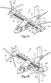
- Aircraft 10 includes a fuselage 12, a wing mount assembly 14 that is rotatable relative to fuselage 12 and a tail assembly 16 having control surfaces operable for horizontal and/or vertical stabilization during forward flight.
- a wing 18 is supported by wing mount assembly 14 and rotates with wing mount assembly 14 relative to fuselage 12 to enable tiltrotor aircraft 10 convert to a storage configuration.
- fuselage 12, tail assembly 16 and wing 18 as well as their various frames, longerons, stringers, bulkheads, spars, ribs, skins and the like may be considered to be the airframe of tiltrotor aircraft 10.
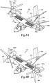
- a pylon assembly 22a is rotatable relative to fixed nacelle 20a and wing 18 between a generally vertical orientation, as best seen in figure 1A , a generally horizontal orientation, as best seen in figure 1B .
- Pylon assembly 22a includes a rotatable portion of the drive system and a proprotor assembly 24a that is rotatable responsive to torque and rotational energy provided via the engine and drive system.
- a pylon assembly 22b is rotatable relative to fixed nacelle 20b and wing 18 between a generally vertical orientation, as best seen in figure 1A , a generally horizontal orientation, as best seen in figure 1B .
- Pylon assembly 22b includes a rotatable portion of the drive system and a proprotor assembly 24b that is rotatable responsive to torque and rotational energy provided via the engine and drive system.
- proprotor assemblies 24a, 24b each include five proprotor blades 26. It should be understood by those having ordinary skill in the art, however, that proprotor assemblies 24a, 24b could alternatively have a different number of proprotor blades, either less than or greater than five.
- wing 18 Distributed generally spanwise within wing 18 is a plurality of propulsion assemblies depicted as cycloidal rotors 28a-28h.
- cycloidal rotors 28a-28h are located in wing 18 to the left side of fuselage 12 and four cycloidal rotors 28e-28h are located in wing 18 to the right side of fuselage 12.
- each side of wing 18 could alternatively have a different number of cycloidal rotors, either less than or greater than four, positioned spanwise or in another suitable configuration.
- Cycloidal rotors 28a-28h provide vertical lift and hover augmentation to tiltrotor aircraft 10 in the helicopter flight mode.
- Vertical thrust generated by cycloidal rotors 28a-28h is operable to provide vertical lift augmentation tiltrotor aircraft 10. This reduces the vertical thrust requirement of proprotor assemblies 24a, 24b, thereby enabling proprotor assemblies 24a, 24b to be tailored more toward the higher inflow and lower blade loading environment experience by proprotor assemblies 24a, 24b in the forward flight mode of tiltrotor aircraft 10.
- the tailoring of proprotor assemblies 24a, 24b may include the use of shorter proprotor blades, the uses of proprotor blades having greater twist and/or the use of a greater number of proprotor blades on each proprotor assembly, to name a few.
- Thrust vectoring by cycloidal rotors 28a-28h is operable to provide hover augmentation to tiltrotor aircraft 10. This reduces or eliminates the thrust vectoring requirement of proprotor assemblies 24a, 24b, thereby reducing the complexity of proprotor operation and the proprotor control system including, for example, elimination of the cyclic operation and cyclic control system of proprotor assemblies 24a, 24b.
- cycloidal rotors 28a-28h reduce the download on wing 18 during hover operations by ingesting a portion of the hover column of air deflected by proprotor assemblies 24a, 24b that would typically be blocked by wing 18, which improves the hover efficiency of tiltrotor aircraft 10.
- Figure 1A illustrates aircraft 10 in helicopter or VTOL flight mode, in which proprotor assemblies 24a, 24b are rotating in a substantially horizontal plane to provide a lifting thrust, such that aircraft 10 flies much like a conventional helicopter, with the addition of cycloidal rotors 28a-28h providing vertical lift and hover augmentation.
- Figures 1B and 1C illustrate aircraft 10 in airplane or forward flight mode, in which proprotor assemblies 24a, 24b are rotating in a substantially vertical plane to provide a forward thrust enabling wing 18 to provide a lifting force responsive to forward airspeed, such that aircraft 10 flies much like a conventional propeller driven aircraft.
- cycloidal rotors 28a-28h are exposed and may be operated if desired to pass air through wing 18 at a desired rate or may be allowed to freewheel responsive to airflow across wing 18.
- covers 30 may be hydraulically actuated to provide aerodynamic surfaces substantially coincident with the upper and lower skins of wing 18 when it is not desired to have cycloidal rotors 28a-28h exposed.
- proprotor assemblies 24a, 24b rotate in opposite directions to provide torque balancing to aircraft 10. For example, when viewed from the front of aircraft 10 in forward flight mode, proprotor assembly 24a rotates clockwise and proprotor assembly 24b rotates counterclockwise. It should be appreciated that aircraft 10 can be operated such that proprotor assemblies 24a, 24b are selectively positioned between airplane flight mode and helicopter flight mode, which can be referred to as a conversion flight mode.
- tiltrotor aircraft 10 the embodiments of the present disclosure can be implemented on other types of tiltrotor aircraft including, for example, quad tiltrotor aircraft, unmanned tiltrotor aircraft and blended wing body aircraft, to name a few.
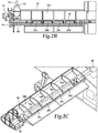
- the drive system includes an engine 40 that is fixed relative to wing 18.
- An engine output shaft 42 transfers power from engine 40 to a spiral bevel gearbox 44 that includes spiral bevel gears to change torque direction by 90 degrees from engine 40 to a fixed gearbox 46.
- Fixed gearbox 46 includes a plurality of gears, such as helical gears, in a gear train that are coupled to a drive shaft 48 and an output shaft (not visible) that transfers torque from fixed gearbox 46 to spindle gearbox 50, which is part of proprotor gearbox 52.
- Proprotor gearbox 46 is configured to transfer power and reduce speed to mast 54 that is operable to rotate a proprotor assembly (not pictured). In this manner, engine 40 provides torque and rotational energy to a proprotor assembly.
- Drive shaft 48 provides a torque path that enables rotation of the propulsion assemblies depicted as cycloidal rotors 28a-28d.
- cycloidal rotors 28a-28d are respectively disposed in individual channels 56a-56d that extend between an upper surface 18a and a lower surface 18b of wing 18 aft of wing spar 58 (note that upper surface 18a has been removed for clarity in figures 2B, 2C ).
- engine 40 provides torque and rotational energy to cycloidal rotors 28a-28d.
- cycloidal rotors 28a-28d may receive torque and rotational energy from a dedicated engine, such as engine 60 located in fuselage 12, which may be a liquid fuel powered engine or an electric motor.
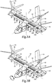
- Cycloidal rotors 28a-28h generate vertical thrust for tiltrotor aircraft 10 to provide vertical lift augmentation to proprotor assemblies 24a, 24b when tiltrotor aircraft 10 is in helicopter flight mode, as indicated by the large vertical arrows in figure 3A .
- the vertical lift augmentation is particularly useful during vertical takeoff, vertical landing and hover but may also be useful during other operations in helicopter flight mode as well as airplane flight mode, if desired.
- Cycloidal rotors 28a-28h also enabling certain maneuvers in the helicopter flight mode of tiltrotor aircraft 10, which are collectively referred to herein as "hover augmentation.” It is noted that the term “hover augmentation” does not imply that tiltrotor aircraft 10 remains in one place in the air during such maneuvers but rather that tiltrotor aircraft 10 is configured in the helicopter flight mode during the maneuvers such as changing elevation, moving laterally, moving forward, moving backwards or the like.
- Operation of cycloidal rotors 28a-28h can enable roll control over tiltrotor aircraft 10 by selectively providing a greater vertical thrust on one side of tiltrotor aircraft 10 as compared to the other side of tiltrotor aircraft 10, as indicated by the large vertical arrows associated with cycloidal rotors 28a-28d and the small vertical arrows associated with cycloidal rotors 28e-28h in figure 3B .
- cycloidal rotors 28a-28h provide additional hover augmentation capability to tiltrotor aircraft 10.
- Operation of cycloidal rotors 28a-28h can enable yaw control over tiltrotor aircraft 10 by selectively providing a forward thrust component on one side of tiltrotor aircraft 10 and an aft thrust component on the other side of tiltrotor aircraft 10, as indicated by the large arrows with an aft component associated with cycloidal rotors 28a-28d and the large arrows with a forward component associated with cycloidal rotors 28e-28h in figure 3C .
- Operation of cycloidal rotors 28a-28h can enable fore/aft control over tiltrotor aircraft 10 by selectively providing a forward or an aft thrust component on both sides of tiltrotor aircraft 10, as indicated by the large arrows with an aft component associated with cycloidal rotors 28a-28h in figure 3D .
- operation of cycloidal rotors 28a-28h can enable lateral control over tiltrotor aircraft 10 by selectively providing a lateral thrust component on both sides of tiltrotor aircraft 10, as indicated by the large arrows with a lateral component associated with cycloidal rotors 28a, 28b, 28g, 28h, which have been oriented generally chordwise relative to wing 18 in figure 3E .
- operation of cycloidal rotors 28a-28i can enable pitch control over tiltrotor aircraft 10 by selectively providing a vertical thrust component generated proximate an aft location of tiltrotor aircraft 10, as indicated by the large vertical arrow associated with cycloidal rotor 28i in figure 3F .
- cycloidal rotors of the present disclosure have been discussed in terms of providing vertical lift or a vertical thrust in the up direction, those having ordinary skill in the art will recognize that the cycloidal rotors of the present disclosure are capable of not only providing a variable thrust intensity, in the vertical direction, but also a reversible thrust such that vertical thrust in the down direction can also be generated. This feature is important for cycloidal rotor 28i in figure 3F , as pitch control over tiltrotor aircraft 10 will require variable and reversible thrust capability.
- Cycloidal rotor 28A includes a rotor assembly 102 including driver plates 104, 106 which are coupled to and are rotatable about a longitudinal axis by drive shaft 48.
- Drive shaft 48 is part of a drive system used to provide rotational energy to rotor assembly 102 and is, for example, coupled to engine 40 and/or engine 60 of tiltrotor aircraft 10.
- Rotor assembly 102 includes a plurality of blades 108 that are each rotatably coupled between driver plates 104, 106. As illustrated, blades 108 are disposed radially outwardly from the longitudinal axis such that blades 108 follow a generally circular path of travel when rotor assembly 102 rotates about the longitudinal axis.
- Cycloidal rotor 28A includes a control assembly 110 that is coupled to each blade 108.
- Control assembly 110 is part of an actuation system used to adjust the thrust output and thrust vector of rotor assembly 102 and is preferably coupled to an electrically operated actuator controlled by the flight control system and/or pilot input.
- control assembly 110 includes a control cam 112 that is rotatable with and eccentrically shiftable relative to rotor assembly 102.
- Control assembly 110 also includes a plurality of linkages 114 that are slidably coupled to control cam 112 via follower pins 116 in follower slots 118 of driver plate 104 and fixably coupled to blades 108 via driver pins 120 that extend through linkage holes (not visible) of driver plate 104.
- blades 108 are in a neutral configuration wherein blades 108 have a substantially zero pitch during the entire revolution of rotor assembly 102. In this neutral configuration, blades 108 have a substantially zero angle of attack and therefore produce little or no thrust.
- blades 108 are rotated relative to driver plates 104, 106 in response to shifting control cam 112 to an eccentric position, such as a downward position, relative to rotor assembly 102, as best seen in figure 4C .
- control cam 112 is position eccentrically relative to rotor assembly 102 and rotor assembly 102 is rotated by drive shaft 48, follower pins 116 cyclically slide within follower slots 118 which cyclically pivot linkages 114 and cyclically rotates blades 118 relative to driver plates 104, 106.
- the center of rotation of control cam 112 has been shifted down from a concentric location 122 to an eccentric location 124.
- the blades transition between positive pitch, zero pitch, negative pitch, zero pitch and back to positive pitch during each revolution of rotor assembly 102.
- blades 108 have an airfoil cross section and travel in a counterclockwise direction as indicated by arrow 126. As best seen in figure 4C , as blades 108 approach the top of rotor assembly 102, the blades have progressively greater positive pitch reaching a maximum positive pitch proximate axis 130. Thereafter, as blades 108 retreat from the top of rotor assembly 102, the blades have progressively lesser positive pitch reaching zero pitch proximate axis 128. As blades 108 approach the bottom of rotor assembly 102, the blades have progressively greater negative pitch reaching a maximum negative pitch proximate axis 130.
- control cam 112 is operable to change the pitch angle configuration of blades 108 to selectively generate a variable and reversible vertical thrust with vertical movement of control cam 112 and a variable thrust vector with horizontal movement of control cam 112, while operating rotor assembly 102 at a constant speed.
- blades 108 may have an infinite number of pitch angle configurations producing an infinite number of thrust magnitudes and thrust vectors, by moving control cam 112 eccentrically relative to concentric location 122.
- each blade 108 forms an acute angle with respect to the linkage 114 to which it is coupled.
- control cam 112 is shifted down from concentric location 122 to eccentric location 124, airflow through rotor assembly 102 is from the top to the bottom, which generates a vertical thrust in the up direction, as discussed herein.
- the magnitude of the thrust generated by cycloidal rotor 28A is determined by factors including the magnitude of the eccentricity applied to control cam 112, the rotational speed of rotor assembly 102, the cross sectional shape of blades 108, the pitch angle configuration of blades 108, the number of blades 108 and other factors known to those having ordinary skill in the art.
- cycloidal rotors of the present disclosure may take a variety of forms and may operate in a variety of ways.
- a propulsion assembly of the present disclosure is depicted as cycloidal rotor 200.
- cycloidal rotor 200 rotates in the clockwise direction, the blades form obtuse angles with respect to the linkages, the control cam does not rotate with the rotor assembly and the control cam is shifted in same direction in which thrust is generated.
- Cycloidal rotor 200 includes a rotor assembly 202 including driver plates 204, 206 which are coupled to and are rotatable about a longitudinal axis by a drive shaft 48, which is part of a drive system used to provide rotational energy to rotor assembly 202 and is, for example, coupled to engine 40 and/or engine 60 of tiltrotor aircraft 10.
- Rotor assembly 202 includes a plurality of blades 208 that are each rotatably coupled between driver plates 204, 206. As illustrated, blades 208 are disposed radially outwardly from the longitudinal axis such that blades 208 follow a generally circular path of travel when rotor assembly 202 rotates about the longitudinal axis.
- Cycloidal rotor 200 includes a control assembly 210 that is coupled to each blade 208.
- Control assembly 210 is part of an actuation system used to adjust the thrust output and thrust vector of rotor assembly 202.
- control assembly 210 includes a control cam 212 that is eccentrically shiftable relative to rotor assembly 202 but does not rotate with rotor assembly 202.
- Control assembly 210 also includes a plurality of linkages 214 that are slidably coupled to control cam 212 via follower pins 216 in a continuous follower slot 218 of driver plate 204 and fixably coupled to blades 208 via driver pins 220 that extend through linkage holes (not visible) of driver plate 204.
- blades 208 are in a neutral configuration wherein blades 208 have a substantially zero pitch during the entire revolution of rotor assembly 202. In this neutral configuration, blades 208 have a substantially zero angle of attack and therefore produce little or no thrust. To produce thrust, blades 208 are rotated relative to driver plates 204, 206 in response to shifting control cam 212 eccentrically relative to rotor assembly 202.
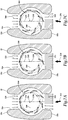
- tiltrotor aircraft 10 includes a plurality of propulsion assemblies with one propulsion assembly, preferably in the form of a cycloidal rotor 200, embedded within each of a plurality of channels, such as channel 56a, extending between upper surface 18a and lower surface 18b of wing 18, which is depicted in cross section.
- the control cam of cycloidal rotor 200 is positioned in the concentric location.
- the blades are in a neutral configuration wherein the blades have a substantially zero pitch during the entire revolution of cycloidal rotor 200.
- cycloidal rotor 200 In this neutral configuration, the blades have a substantially zero angle of attack and therefore produce little or no thrust. Nonetheless, some air may pass through cycloidal rotor 200 as indicated by low-density intake airflow arrows 230 and low-density discharge airflow arrows 232.
- having cycloidal rotor 200 rotating in the no thrust configuration may be preferred to shutting down cycloidal rotor 200 as a nonrotating unit may generate an undesirable drag force while a rotating unit allows for suitable airflow therethrough, as shown in figure 6A .
- the rotating speed of a non thrust-producing unit can be optimized for passive airflow therethrough by the flight control system of tiltrotor aircraft 10.
- the control cam may be shifted up from a concentric location 234 to an eccentric location 236, as seen in figure 6B .
- the blades have a pitch angle configuration wherein the blades transition between positive pitch, zero pitch, negative pitch, zero pitch and back to positive pitch during each revolution of cycloidal rotor 200.
- the blades have an airfoil cross section and travel in a counterclockwise direction. As each blade approaches the intake of channel 56a, the blades have progressively greater positive pitch reaching a maximum positive pitch proximate axis 238.
- each blade has progressively lesser positive pitch reaching zero pitch proximate axis 240.
- the blades have progressively greater negative pitch reaching a maximum negative pitch proximate axis 238.
- the blades have progressively lesser negative pitch, reaching zero pitch proximate axis 240.
- Each blade repeats this cycle on each revolution of cycloidal rotor 200.
- the magnitude of thrust generated by cycloidal rotor 200 is determined by factors including the magnitude of the eccentricity applied to the control cam.
- the control cam may be shifted up from eccentric location 236 to a further eccentric location 248, as seen in figure 6C .
- the blades have a pitch angle configuration wherein the blades transition between positive pitch, zero pitch, negative pitch, zero pitch and back to positive pitch during each revolution of cycloidal rotor 200.
- the blades As each blade approaches the intake of channel 56a, the blades have progressively greater positive pitch reaching a maximum positive pitch proximate axis 238, which is greater than the maximum positive pitch in the pitch angle configuration of the blades in figure 6B . Thereafter, as each blade retreats from the intake, the blades have progressively lesser positive pitch reaching zero pitch proximate axis 240. As each blade approaches the discharge of channel 56a, the blades have progressively greater negative pitch reaching a maximum negative pitch proximate axis 238, which is greater than the maximum negative pitch in the pitch angle configuration of the blades in figure 6B . Thereafter, as each blade retreats from the discharge, the blades have progressively lesser negative pitch, reaching zero pitch proximate axis 240.
- each blade repeats this cycle on each revolution of cycloidal rotor 200.
- air passes through cycloidal rotor 200 gaining energy as indicated by low-density intake airflow arrows 250 and high-density discharge airflow arrows 252 with the resultant thrust indicated by large arrow 254, which is greater than the thrust indicated by small arrow 246 in figure 6B .
- Operating each of the wing mounted cycloidal rotors of tiltrotor aircraft 10 with the blades in the illustrated pitch angle configuration of figure 6C may be desirable for vertical lift augmentation for tiltrotor aircraft 10.
- operating certain of the wing mounted cycloidal rotors of tiltrotor aircraft 10 with the blades in the pitch angle configuration of figure 6B and other of the wing mounted cycloidal rotors of tiltrotor aircraft 10 with the blades in the pitch angle configuration of figure 6C may be desirable for hover augmentation for tiltrotor aircraft 10, for example, in roll control (see figure 3B ).
- the thrust vector generated by cycloidal rotor 200 is determined by factors including the eccentricity applied to the control cam.
- the control cam may be shifted left from eccentric location 248, as seen in figure 7B , to an eccentric location 256, as seen in figure 7A .
- the blades have a pitch angle configuration wherein the blades transition between positive pitch, zero pitch, negative pitch, zero pitch and back to positive pitch during each revolution of cycloidal rotor 200.
- the blades As each blade approaches and passes the intake of channel 56a, the blades have progressively greater positive pitch reaching a maximum positive pitch approximately thirty degrees after axis 238. Thereafter, as each blade retreats from the intake, the blades have progressively lesser positive pitch reaching zero pitch approximately thirty degrees after axis 240. As each blade approaches and passes the discharge of channel 56a, the blades have progressively greater negative pitch reaching a maximum negative pitch approximately thirty degrees after axis 238. Thereafter, as each blade retreats from the discharge, the blades have progressively lesser negative pitch, reaching zero pitch approximately thirty degrees after axis 240. Each blade repeats this cycle on each revolution of cycloidal rotor 200.
- each of the wing mounted cycloidal rotors of tiltrotor aircraft 10 with the blades in the illustrated pitch angle configuration of figure 7A may be desirable for vertical lift augmentation and hover augmentation for tiltrotor aircraft 10, for example, in fore/aft control (see figure 3D ).
- the control cam may be shifted right from eccentric location 256, as seen in figure 7A , to an eccentric location 264, as seen in figure 7C .
- the blades have a pitch angle configuration wherein the blades transition between positive pitch, zero pitch, negative pitch, zero pitch and back to positive pitch during each revolution of cycloidal rotor 200.
- the blades As each blade approaches the intake of channel 56a, the blades have progressively greater positive pitch reaching a maximum positive pitch approximately thirty degrees before axis 238. Thereafter, as each blade retreats from the intake, the blades have progressively lesser positive pitch reaching zero pitch approximately thirty degrees before axis 240.
- each blade As each blade approaches the discharge of channel 56a, the blades have progressively greater negative pitch reaching a maximum negative pitch approximately thirty degrees before axis 238. Thereafter, as each blade retreats from the discharge, the blades have progressively lesser negative pitch, reaching zero pitch approximately thirty degrees before axis 240. Each blade repeats this cycle on each revolution of cycloidal rotor 200. As the blades follow the generally circular path of travel with the cyclically varying angle of attack, air passes through cycloidal rotor 200 gaining energy as indicated by low-density intake airflow arrows 266 and a gradient of discharge airflow arrows 268 with a high-density portion to the left, which has a resultant thrust vector indicated by large arrow 270.
- each of the wing mounted cycloidal rotors of tiltrotor aircraft 10 with the blades in the illustrated pitch angle configuration of figure 7B may be desirable for vertical lift augmentation and hover augmentation for tiltrotor aircraft 10, for example, in fore/aft control (see figure 3D ).
- operating certain of the wing mounted cycloidal rotors of tiltrotor aircraft 10 with the blades in the pitch angle configuration of figure 7A and other of the wing mounted cycloidal rotors of tiltrotor aircraft 10 with the blades in the pitch angle configuration of figure 7C may be desirable for vertical lift augmentation and hover augmentation for tiltrotor aircraft 10, for example, in yaw control (see figure 3C ).
- Aircraft 310 includes a fuselage 312, a wing mount assembly 314 that is rotatable relative to fuselage 312 and a tail assembly 316 having control surfaces operable for horizontal and/or vertical stabilization during forward flight.
- a swept wing 318 is supported by wing mount assembly 314 and rotates with wing mount assembly 314 relative to fuselage 312 to enable tiltrotor aircraft 310 convert to a storage configuration.
- fuselage 312, tail assembly 316 and wing 318 as well as their various frames, longerons, stringers, bulkheads, spars, ribs, skins and the like may be considered to be the airframe of tiltrotor aircraft 310.
- a pylon assembly 322a is rotatable relative to fixed nacelle 320a and wing 318 between a generally vertical orientation, as best seen in figure 8A , a generally horizontal orientation, as best seen in figure 8B .
- Pylon assembly 322a includes a rotatable portion of the drive system and a proprotor assembly 324a that is rotatable responsive to torque and rotational energy provided via the engine and drive system.
- a pylon assembly 322b is rotatable relative to fixed nacelle 320b and wing 318 between a generally vertical orientation, as best seen in figure 8A , a generally horizontal orientation, as best seen in figure 8B .
- Pylon assembly 322b includes a rotatable portion of the drive system and a proprotor assembly 324b that is rotatable responsive to torque and rotational energy provided via the engine and drive system.
- proprotor assemblies 324a, 324b each include five proprotor blades 326.
- Distributed in arrays within wing 318 is a plurality of propulsion assemblies depicted as cycloidal rotors 328.
- six cycloidal rotors 328 form a two by three array located in wing 318 to the left side of fuselage 312 and six cycloidal rotors 328 form a two by three array located in wing 318 to the right side of fuselage 312. It should be understood by those having ordinary skill in the art, however, that each side of wing 318 could alternatively have a different number of cycloidal rotors in a different array or a different relative configuration.
- Cycloidal rotors 328 provide vertical lift and hover augmentation to tiltrotor aircraft 310 in the helicopter flight mode.
- Vertical thrust generated by cycloidal rotors 328 is operable to provide vertical lift augmentation tiltrotor aircraft 10.
- Thrust vectoring by cycloidal rotors 328 is operable to provide hover augmentation to tiltrotor aircraft 10 such as roll control, yaw control, fore/aft control and/or lateral control if certain of cycloidal rotors 328 are positioned in the chordwise direction.
- cycloidal rotors 328 are able to generated a pitch moment due to the fore/aft offset between forward mounted cycloidal rotors 328 and aft mounted cycloidal rotors 328 such that vertical thrust generated by cycloidal rotors 328 is operable to provide hover augmentation to tiltrotor aircraft 10 in the form of pitch control.
- Figure 8A illustrates aircraft 310 in helicopter or VTOL flight mode, in which proprotor assemblies 324a, 324b are rotating in a substantially horizontal plane to provide a lifting thrust, such that aircraft 310 flies much like a conventional helicopter, with the addition of cycloidal rotors 328 providing vertical lift and hover augmentation.
- Figure 8B illustrates aircraft 310 in airplane or forward flight mode, in which proprotor assemblies 324a, 324b are rotating in a substantially vertical plane to provide a forward thrust enabling wing 318 to provide a lifting force responsive to forward airspeed, such that aircraft 310 flies much like a conventional propeller driven aircraft.
- cycloidal rotors 328 are exposed and may be operated if desired to pass air through wing 318 at a desire rate or may be allowed to freewheel responsive to airflow across wing 318.
- covers may be hydraulically actuated to provide aerodynamic surfaces substantially coincident with the upper and lower skins of wing 318 when it is not desired to have cycloidal rotors 328 exposed.
Landscapes
- Engineering & Computer Science (AREA)
- Aviation & Aerospace Engineering (AREA)
- Mechanical Engineering (AREA)
- Remote Sensing (AREA)
- Chemical & Material Sciences (AREA)
- Combustion & Propulsion (AREA)
- Transmission Devices (AREA)
Claims (14)
- Aéronef à rotors basculants (10) ayant un mode vol hélicoptère et un mode vol avion, l'aéronef à rotors basculants comprenant :un fuselage (12) ;une aile (18) supportée par le fuselage (12), l'aile ayant des surfaces supérieure et inférieure (18a-b) avec une pluralité de canaux (56a-d) s'étendant entre elles ;une pluralité d'ensembles de propulsion (28a-28h), chacun étant disposé dans l'un de la pluralité de canaux (56a-d) de l'aile (18) et caractérisé par :au moins deux ensembles pylônes (22a-b), chacun étant couplé de manière rotative à l'aile (18) pour actionner sélectivement l'aéronef à rotors basculants (10) entre le mode vol hélicoptère et le mode vol avion, chaque ensemble pylône (22a-b) incluant un mât (54) et un ensemble rotor orientable servant à tourner avec le mât (54) pour générer une poussée ; etau moins un moteur (40) fournissant du couple et de l'énergie de rotation aux ensembles rotors orientables (24a-b) et aux ensembles de propulsion (28a-28h).
- Aéronef à rotors basculants (10) selon la revendication 1 dans lequel les ensembles de propulsion (28a-28h) fournissent une augmentation de portance verticale et de vol stationnaire aux ensembles rotors orientables (24a-b) dans le mode vol hélicoptère.
- Aéronef à rotors basculants (10) selon la revendication 1 ou la revendication 2 dans lequel chacun des ensembles de propulsion (28a-28h) sert à fournir une poussée verticale.
- Aéronef à rotors basculants (10) selon la revendication 1 ou la revendication 2 ou la revendication 3 dans lequel chacun des ensembles de propulsion (28a-28h) sert à fournir une poussée variable.
- Aéronef à rotors basculants (10) selon la revendication 1 ou l'une quelconque des revendications 2 à 4 dans lequel chacun des ensembles de propulsion (28a-28h) sert à fournir un vecteur de poussée variable.
- Aéronef à rotors basculants (10) selon la revendication 1 ou l'une quelconque des revendications 2 à 5 dans lequel les ensembles de propulsion (28a-28h) sont répartis globalement dans le sens de l'envergure dans l'aile (18).
- Aéronef à rotors basculants (10) selon la revendication 1 ou l'une quelconque des revendications 2 à 6 dans lequel la pluralité d'ensembles de propulsion (28a-28h) comprennent en outre une pluralité avant d'ensembles de propulsion et une pluralité arrière d'ensembles de propulsion (28a-28h).
- Aéronef à rotors basculants (10) selon la revendication 1 ou l'une quelconque des revendications 2 à 7 dans lequel la pluralité d'ensembles de propulsion (28a-28h) servent à générer une poussée verticale pour augmenter la poussée des ensembles rotors orientables (24a-b) dans le mode vol hélicoptère.
- Aéronef à rotors basculants (10) selon la revendication 1 ou l'une quelconque des revendications 2 à 8 dans lequel les ensembles de propulsion (28a-28h) servent à une vectorisation de poussée pour fournir une augmentation de vol stationnaire dans le mode vol hélicoptère.
- Aéronef à rotors basculants (10) selon la revendication 1 ou l'une quelconque des revendications 2 à 9 dans lequel la pluralité d'ensembles de propulsion (28a-28h) servent à fournir une commande de roulis dans le mode vol hélicoptère.
- Aéronef à rotors basculants (10) selon la revendication 1 ou l'une quelconque des revendications 2 à 10 dans lequel la pluralité d'ensembles de propulsion (28a-28h) servent à fournir une commande de lacet dans le mode vol hélicoptère.
- Aéronef à rotors basculants (10) selon la revendication 1 ou l'une quelconque des revendications 2 à 11 dans lequel la pluralité d'ensembles de propulsion (28a-28h) servent à fournir une commande de tangage dans le mode vol hélicoptère.
- Aéronef à rotors basculants (10) selon la revendication 1 ou l'une quelconque des revendications 2 à 12 dans lequel l'au moins un moteur (40) comprend en outre au moins un moteur dédié à la pluralité d'ensembles de propulsion (28a-28h).
- Aéronef à rotors basculants (10) selon la revendication 1 ou l'une quelconque des revendications 2 à 13 comprenant en outre des caches aérodynamiques servant à fermer les canaux (56a-d) de l'aile (18).
Applications Claiming Priority (1)
| Application Number | Priority Date | Filing Date | Title |
|---|---|---|---|
| US15/438,972 US10384776B2 (en) | 2017-02-22 | 2017-02-22 | Tiltrotor aircraft having vertical lift and hover augmentation |
Publications (2)
| Publication Number | Publication Date |
|---|---|
| EP3366583A1 EP3366583A1 (fr) | 2018-08-29 |
| EP3366583B1 true EP3366583B1 (fr) | 2019-07-17 |
Family
ID=60674042
Family Applications (1)
| Application Number | Title | Priority Date | Filing Date |
|---|---|---|---|
| EP17208612.6A Active EP3366583B1 (fr) | 2017-02-22 | 2017-12-19 | Aéronef à rotors basculants présentant une augmentation de poussée pour le vol stationnaire et vertical |
Country Status (2)
| Country | Link |
|---|---|
| US (1) | US10384776B2 (fr) |
| EP (1) | EP3366583B1 (fr) |
Families Citing this family (33)
| Publication number | Priority date | Publication date | Assignee | Title |
|---|---|---|---|---|
| AT518116B1 (de) * | 2015-12-30 | 2019-05-15 | Cyclotech Gmbh | Fluggerät |
| WO2018140199A2 (fr) * | 2017-01-03 | 2018-08-02 | The Texas A&M University System | Microvéhicule aérien à rotor cycloïdal |
| US10421540B1 (en) * | 2017-03-02 | 2019-09-24 | Bell Textron Inc. | Tiltrotor aircraft having optimized hover capabilities |
| DE102017011890B4 (de) * | 2017-12-14 | 2023-02-09 | Cyclotech Gmbh | Antriebsvorrichtung für ein Fluggerät |
| WO2019217920A1 (fr) | 2018-05-10 | 2019-11-14 | Joby Aero, Inc. | Aéronef électrique à rotors basculants |
| US12006048B2 (en) | 2018-05-31 | 2024-06-11 | Joby Aero, Inc. | Electric power system architecture and fault tolerant VTOL aircraft using same |
| WO2019232472A1 (fr) | 2018-05-31 | 2019-12-05 | Joby Aero Inc. | Architecture de système d'alimentation électrique et aéronef à décollage et atterrissage verticaux (vtol) tolérant aux pannes le mettant en oeuvre |
| JP7130064B2 (ja) | 2018-06-01 | 2022-09-02 | ジョビー エアロ,インコーポレイテッド | 航空機の騒音緩和システムおよび方法 |
| US10710741B2 (en) | 2018-07-02 | 2020-07-14 | Joby Aero, Inc. | System and method for airspeed determination |
| WO2020023166A1 (fr) * | 2018-07-27 | 2020-01-30 | Walmart Apollo, Llc | Véhicule aérien sans pilote hybride pour la livraison de marchandises |
| WO2020061085A1 (fr) | 2018-09-17 | 2020-03-26 | Joby Aero, Inc. | Système de commande d'aéronef |
| WO2020059155A1 (fr) * | 2018-09-22 | 2020-03-26 | 株式会社エアロネクスト | Aéronef |
| AU2019433213B2 (en) | 2018-12-07 | 2025-06-05 | Joby Aero, Inc. | Aircraft control system and method |
| WO2020118310A1 (fr) | 2018-12-07 | 2020-06-11 | Joby Aero, Inc. | Profil aérodynamique rotatif et son procédé de conception |
| US10845823B2 (en) | 2018-12-19 | 2020-11-24 | Joby Aero, Inc. | Vehicle navigation system |
| US11427300B2 (en) * | 2019-03-29 | 2022-08-30 | Copperhead Aeronautics, Llc | Lift nacelle |
| US11230384B2 (en) | 2019-04-23 | 2022-01-25 | Joby Aero, Inc. | Vehicle cabin thermal management system and method |
| EP4538182A3 (fr) | 2019-04-23 | 2025-09-03 | Joby Aero, Inc. | Système et procédé de gestion thermique de batterie |
| EP3959127A4 (fr) | 2019-04-25 | 2023-01-11 | Joby Aero, Inc. | Aéronef vtol |
| EP3757004B1 (fr) * | 2019-06-27 | 2023-03-29 | Volocopter GmbH | Aéronef vtol avec des poutres de connexion d'ailes |
| US11554865B2 (en) * | 2020-02-18 | 2023-01-17 | Aurora Flight Sciences Corporation | Vertical take-off and landing (VTOL) aircraft and related methods |
| JP7346347B2 (ja) * | 2020-03-25 | 2023-09-19 | 三菱重工業株式会社 | 翼及び航空機 |
| MY202190A (en) * | 2020-03-26 | 2024-04-16 | Chung How Poh | A vtol-capable airplane having angled propulsors |
| US11142302B1 (en) | 2020-03-28 | 2021-10-12 | Textron Innovations Inc. | Fluidic split flap systems for yaw control in forward flight |
| EP4162473A4 (fr) | 2020-06-05 | 2024-07-03 | Joby Aero, Inc. | Procédé et système de commande d'aéronef |
| US11591081B2 (en) * | 2020-06-08 | 2023-02-28 | Textron Innovations Inc. | Vertical-lift augmentation system |
| US11614754B2 (en) * | 2020-08-11 | 2023-03-28 | Pitch Aeronautics LLC | Multirotor vertical takeoff and landing aircraft with cyclorotor for lateral control |
| US11661172B2 (en) * | 2020-12-31 | 2023-05-30 | Textron Innovations Inc. | Wing design for removable battery |
| JP6938005B1 (ja) * | 2021-01-09 | 2021-09-22 | 知生 島宗 | 飛行体システム、および飛行体制御プログラム |
| EP4091939B1 (fr) | 2021-05-21 | 2025-01-22 | CycloTech GmbH | Aéronef |
| US12291329B2 (en) * | 2022-05-05 | 2025-05-06 | Ramon David Bermudez Onopa | Integrated thrust-lift wing |
| US12084176B2 (en) * | 2022-10-11 | 2024-09-10 | The Boeing Company | Aircraft, a control system for the aircraft and a method of controlling the aircraft |
| CN121376140A (zh) * | 2025-11-18 | 2026-01-23 | 中国航发控制系统研究所 | 基于高减速比传动的eVTOL短舱倾转舵机及工作方法 |
Family Cites Families (64)
| Publication number | Priority date | Publication date | Assignee | Title |
|---|---|---|---|---|
| US1487228A (en) | 1924-01-25 | 1924-03-18 | Garcia Emilio | Aeroplane |
| FR636843A (fr) | 1926-06-30 | 1928-04-17 | Ailes rotatives | |
| US1666132A (en) | 1927-07-28 | 1928-04-17 | Gallet Maurice | Aeroplane |
| US1936786A (en) | 1931-04-17 | 1933-11-28 | Gebhert Albert | Aircraft wings |
| FR880130A (fr) | 1941-09-29 | 1943-03-15 | Perfectionnements aux avions | |
| US2402311A (en) | 1943-09-17 | 1946-06-18 | Ernest E Bissett | Airplane |
| US2479125A (en) | 1943-10-06 | 1949-08-16 | Lloyd H Leonard | Variable attitude helicopter airplane |
| US2444781A (en) | 1943-12-08 | 1948-07-06 | Lloyd H Leonard | Axial flow helicopter |
| US2526941A (en) | 1948-06-10 | 1950-10-24 | Northrop Aircraft Inc | Gas turbine system for aircraft propulsion |
| US2604276A (en) | 1950-09-12 | 1952-07-22 | Northrop Aircraft Inc | Pusher power plant for airplanes |
| US2866608A (en) | 1955-05-18 | 1958-12-30 | Lloyd H Leonard | Vertical-take-off type aircraft with jet driven rotor system |
| GB885663A (en) | 1956-12-07 | 1961-12-28 | Laing Nikolaus | Improvement relating to aircraft |
| DE1040907B (de) | 1956-12-07 | 1958-10-09 | Nikolaus Laing | Strahlgeblaese fuer Luftfahrzeuge |
| US3059876A (en) | 1958-07-03 | 1962-10-23 | Haviland H Platt | Vertical take-off airplane |
| US3159361A (en) | 1962-02-14 | 1964-12-01 | Carl W Weiland | Aircraft |
| US3178131A (en) | 1963-10-03 | 1965-04-13 | Laing Nikolaus | Aircraft wing structure |
| US4165058A (en) | 1976-01-13 | 1979-08-21 | The Boeing Company | Tandem wing airplane |
| FR2375090A1 (fr) | 1976-12-27 | 1978-07-21 | Chabonat Marcel | Perfectionnements apportes aux rotors sustentateurs propulsifs |
| US4194707A (en) | 1977-12-16 | 1980-03-25 | Sharpe Thomas H | Lift augmenting device for aircraft |
| FR2645828B1 (fr) * | 1989-04-17 | 1991-06-21 | Servanty Pierre | Rotor apte a developper dans un fluide des efforts sustentateurs et/ou propulsifs, procede de pilotage et aeronef equipe d'un tel rotor |
| US5289994A (en) | 1989-10-10 | 1994-03-01 | Juan Del Campo Aguilera | Equipment carrying remote controlled aircraft |
| US5176338A (en) | 1991-03-08 | 1993-01-05 | The United States Of America As Represented By The Secretary Of The Air Force | N-dimensional fighter aircraft |
| US5265827A (en) * | 1991-06-17 | 1993-11-30 | Northrop Corporation | Paddle wheel rotorcraft |
| US5205512A (en) | 1991-08-19 | 1993-04-27 | The Boeing Company | Fluid control apparatus |
| GB2316374A (en) | 1996-08-20 | 1998-02-25 | Patrick Peebles | Fluid dynamic lift generation |
| US6007021A (en) | 1997-11-18 | 1999-12-28 | Tsepenyuk; Mikhail | Flying apparatus for a vertical take off and landing |
| US7654486B2 (en) | 2002-09-11 | 2010-02-02 | Milde Jr Karl F | VTOL personal aircraft |
| US7461811B2 (en) | 2002-09-11 | 2008-12-09 | Milde Jr Karl F | VTOL personal aircraft |
| DE60321390D1 (de) | 2003-01-23 | 2008-07-10 | Bell Helicopter Textron Inc | Propellerblatt mit führungskantennut |
| CN100398397C (zh) | 2003-08-27 | 2008-07-02 | 贝尔直升机泰克斯特龙公司 | 飞机的保护蒙皮 |
| CN101048313A (zh) | 2004-09-28 | 2007-10-03 | 贝尔直升机泰克斯特龙公司 | 用于旋翼飞机的推进反扭矩系统 |
| JP2006152921A (ja) | 2004-11-29 | 2006-06-15 | Sony Corp | 冷却用送風ファン及び映像表示装置 |
| US7159817B2 (en) | 2005-01-13 | 2007-01-09 | Vandermey Timothy | Vertical take-off and landing (VTOL) aircraft with distributed thrust and control |
| WO2006116072A1 (fr) | 2005-04-21 | 2006-11-02 | Syracuse University | Systeme de propulsion par soufflante a flux transversal |
| US7370828B2 (en) | 2005-05-04 | 2008-05-13 | X Blade Systems Lp | Rotary wing aircraft |
| US20070200029A1 (en) | 2006-02-27 | 2007-08-30 | Sullivan Callum R | Hydraulic cycloidal control system |
| JP2009051381A (ja) | 2007-08-28 | 2009-03-12 | Mitsubishi Heavy Ind Ltd | サイクロイダル・ブレード |
| IL199009A (en) | 2009-05-27 | 2013-11-28 | Israel Aerospace Ind Ltd | Air vehicle |
| US8800912B2 (en) | 2009-10-09 | 2014-08-12 | Oliver Vtol, Llc | Three wing, six-tilt propulsion unit, VTOL aircraft |
| US8196855B2 (en) | 2009-11-23 | 2012-06-12 | Balkus Jr Carl E | Helicopter auxiliary anti-torque system |
| US20120111994A1 (en) | 2010-01-15 | 2012-05-10 | Propulsive Wing, LLC | Cross-flow fan propulsion system |
| DE102010032217A1 (de) | 2010-07-26 | 2012-01-26 | Siemens Aktiengesellschaft | Drehmomentenausgleich für einen Helikopter |
| WO2012064345A1 (fr) | 2010-11-12 | 2012-05-18 | Bell Helicopter Textron Inc. | Système de buse propulsive anticouple munie d'un directeur de poussée rotatif pour giravion |
| US8636243B2 (en) | 2010-11-12 | 2014-01-28 | Textron Innovations Inc. | Anti-torque nozzle system with internal sleeve valve for a rotorcraft |
| US8469308B2 (en) | 2010-11-12 | 2013-06-25 | Textron Innovations Inc. | Aircraft wing extension and nozzle system |
| US8596570B1 (en) | 2011-02-22 | 2013-12-03 | David Carambat | Aircraft vehicle centrifugal fan apparatus |
| EP2511177B1 (fr) | 2011-04-11 | 2013-06-05 | Eurocopter Deutschland GmbH | Hélicoptère doté d'un système de rotor cycloïdal |
| EP2551190B1 (fr) | 2011-07-29 | 2013-11-20 | AGUSTAWESTLAND S.p.A. | Avion convertible |
| US9260185B2 (en) | 2012-01-25 | 2016-02-16 | Textron Innovations Inc. | System and method of harvesting power with a rotor hub damper |
| IL222053A (en) | 2012-09-23 | 2016-11-30 | Israel Aerospace Ind Ltd | System, method and computer program product for maneuvering an air vehicle |
| FR2999150B1 (fr) | 2012-12-10 | 2015-10-09 | Bermond Gerome Maurice Paul | Aeronef convertible pourvu de deux rotors carenes en bout d'aile et d'un fan horizontal dans le fuselage |
| EP2808253B1 (fr) | 2013-05-30 | 2016-12-07 | AIRBUS HELICOPTERS DEUTSCHLAND GmbH | Hélicoptère avec ventilateur à écoulement transversal |
| SE541609C2 (sv) | 2013-06-25 | 2019-11-12 | Foersvarets Materielverk | Framdrivningssystem för flygfarkost |
| US9834303B2 (en) * | 2013-08-14 | 2017-12-05 | Bell Helicopter Textron Inc. | Method and apparatus of connecting a fixed drive system to a rotating drive system for a tiltrotor aircraft |
| DE102013020601B4 (de) | 2013-12-11 | 2018-03-22 | Airbus Defence and Space GmbH | Flugzeugkonfiguration |
| US9567075B2 (en) | 2014-02-10 | 2017-02-14 | Northrop Grumman Systems Corporation | Tilt wing aerial vehicle |
| BR112016025875B1 (pt) | 2014-05-07 | 2022-08-23 | XTI Aircraft Company | Aeronave de vtol |
| US9878257B2 (en) | 2014-06-10 | 2018-01-30 | University Of Kansas | Aerial vehicles and methods of use |
| CN104276284B (zh) | 2014-10-08 | 2016-04-20 | 中国航空工业集团公司西安飞机设计研究所 | 一种串列式扇翼飞行器布局 |
| CN204674831U (zh) | 2015-05-13 | 2015-09-30 | 卢逊 | 多扇臂飞行器 |
| JP2017015527A (ja) | 2015-06-30 | 2017-01-19 | 株式会社トプコン | 広域センサシステム、飛行検出方法およびプログラム |
| US10655728B2 (en) | 2015-12-01 | 2020-05-19 | The Boeing Company | Reconfigurable lubrication system for tiltrotor transmission |
| AT518116B1 (de) * | 2015-12-30 | 2019-05-15 | Cyclotech Gmbh | Fluggerät |
| FR3052677A1 (fr) | 2016-06-20 | 2017-12-22 | Parrot Drones | Drone comprenant des ailes portantes. |
-
2017
- 2017-02-22 US US15/438,972 patent/US10384776B2/en active Active
- 2017-12-19 EP EP17208612.6A patent/EP3366583B1/fr active Active
Non-Patent Citations (1)
| Title |
|---|
| None * |
Also Published As
| Publication number | Publication date |
|---|---|
| EP3366583A1 (fr) | 2018-08-29 |
| US10384776B2 (en) | 2019-08-20 |
| US20180237136A1 (en) | 2018-08-23 |
Similar Documents
| Publication | Publication Date | Title |
|---|---|---|
| US10384776B2 (en) | Tiltrotor aircraft having vertical lift and hover augmentation | |
| US10106253B2 (en) | Tilting ducted fan aircraft generating a pitch control moment | |
| EP3486168B1 (fr) | Aéronef à rotors basculants à portée étenduek | |
| US10377480B2 (en) | Apparatus and method for directing thrust from tilting cross-flow fan wings on an aircraft | |
| US10421540B1 (en) | Tiltrotor aircraft having optimized hover capabilities | |
| CA2979607C (fr) | Ailettes d'extension d'aile destinees a un aeronef a rotor basculant | |
| US10421541B2 (en) | Aircraft with tilting cross-flow fan wings | |
| US10843797B2 (en) | Storage modes for tiltrotor aircraft | |
| EP3290337B1 (fr) | Aéronef ayant des capacités de conversion rotor/aile double | |
| US8376264B1 (en) | Rotor for a dual mode aircraft | |
| EP3290338B1 (fr) | Aéronef ayant des capacités de conversion rotor/aile | |
| AU2013360005B2 (en) | Aircraft and methods for operating an aircraft | |
| EP1731420A1 (fr) | Procede de fonctionnement d'un aeronef convertible | |
| EP3243750B1 (fr) | Propulsion répartie | |
| US11396374B2 (en) | Aircraft having radially extendable tailboom assembly | |
| US12202600B1 (en) | High-speed tiltrotor aircraft having a variable-sweep wing | |
| AU2013360005A1 (en) | Aircraft and methods for operating an aircraft | |
| US10293931B2 (en) | Aircraft generating a triaxial dynamic thrust matrix | |
| EP3360780A1 (fr) | Aéronef à rotors basculants ayant des modes de vol rotatifs et non rotatifs | |
| US11254423B2 (en) | Damping landing gear systems for vtol aircraft | |
| US11760475B2 (en) | Articulated tiltrotor | |
| AU2020100605A4 (en) | A vtol-capable airplane having angled propulsors |
Legal Events
| Date | Code | Title | Description |
|---|---|---|---|
| PUAI | Public reference made under article 153(3) epc to a published international application that has entered the european phase |
Free format text: ORIGINAL CODE: 0009012 |
|
| STAA | Information on the status of an ep patent application or granted ep patent |
Free format text: STATUS: REQUEST FOR EXAMINATION WAS MADE |
|
| STAA | Information on the status of an ep patent application or granted ep patent |
Free format text: STATUS: EXAMINATION IS IN PROGRESS |
|
| 17P | Request for examination filed |
Effective date: 20171219 |
|
| AK | Designated contracting states |
Kind code of ref document: A1 Designated state(s): AL AT BE BG CH CY CZ DE DK EE ES FI FR GB GR HR HU IE IS IT LI LT LU LV MC MK MT NL NO PL PT RO RS SE SI SK SM TR |
|
| AX | Request for extension of the european patent |
Extension state: BA ME |
|
| 17Q | First examination report despatched |
Effective date: 20180810 |
|
| GRAP | Despatch of communication of intention to grant a patent |
Free format text: ORIGINAL CODE: EPIDOSNIGR1 |
|
| STAA | Information on the status of an ep patent application or granted ep patent |
Free format text: STATUS: GRANT OF PATENT IS INTENDED |
|
| INTG | Intention to grant announced |
Effective date: 20190408 |
|
| GRAA | (expected) grant |
Free format text: ORIGINAL CODE: 0009210 |
|
| STAA | Information on the status of an ep patent application or granted ep patent |
Free format text: STATUS: THE PATENT HAS BEEN GRANTED |
|
| AK | Designated contracting states |
Kind code of ref document: B1 Designated state(s): AL AT BE BG CH CY CZ DE DK EE ES FI FR GB GR HR HU IE IS IT LI LT LU LV MC MK MT NL NO PL PT RO RS SE SI SK SM TR |
|
| REG | Reference to a national code |
Ref country code: GB Ref legal event code: FG4D |
|
| REG | Reference to a national code |
Ref country code: CH Ref legal event code: EP |
|
| REG | Reference to a national code |
Ref country code: IE Ref legal event code: FG4D |
|
| REG | Reference to a national code |
Ref country code: DE Ref legal event code: R096 Ref document number: 602017005362 Country of ref document: DE |
|
| REG | Reference to a national code |
Ref country code: AT Ref legal event code: REF Ref document number: 1155628 Country of ref document: AT Kind code of ref document: T Effective date: 20190815 |
|
| REG | Reference to a national code |
Ref country code: NL Ref legal event code: MP Effective date: 20190717 |
|
| REG | Reference to a national code |
Ref country code: LT Ref legal event code: MG4D |
|
| REG | Reference to a national code |
Ref country code: AT Ref legal event code: MK05 Ref document number: 1155628 Country of ref document: AT Kind code of ref document: T Effective date: 20190717 |
|
| PG25 | Lapsed in a contracting state [announced via postgrant information from national office to epo] |
Ref country code: HR Free format text: LAPSE BECAUSE OF FAILURE TO SUBMIT A TRANSLATION OF THE DESCRIPTION OR TO PAY THE FEE WITHIN THE PRESCRIBED TIME-LIMIT Effective date: 20190717 Ref country code: LT Free format text: LAPSE BECAUSE OF FAILURE TO SUBMIT A TRANSLATION OF THE DESCRIPTION OR TO PAY THE FEE WITHIN THE PRESCRIBED TIME-LIMIT Effective date: 20190717 Ref country code: BG Free format text: LAPSE BECAUSE OF FAILURE TO SUBMIT A TRANSLATION OF THE DESCRIPTION OR TO PAY THE FEE WITHIN THE PRESCRIBED TIME-LIMIT Effective date: 20191017 Ref country code: SE Free format text: LAPSE BECAUSE OF FAILURE TO SUBMIT A TRANSLATION OF THE DESCRIPTION OR TO PAY THE FEE WITHIN THE PRESCRIBED TIME-LIMIT Effective date: 20190717 Ref country code: NL Free format text: LAPSE BECAUSE OF FAILURE TO SUBMIT A TRANSLATION OF THE DESCRIPTION OR TO PAY THE FEE WITHIN THE PRESCRIBED TIME-LIMIT Effective date: 20190717 Ref country code: PT Free format text: LAPSE BECAUSE OF FAILURE TO SUBMIT A TRANSLATION OF THE DESCRIPTION OR TO PAY THE FEE WITHIN THE PRESCRIBED TIME-LIMIT Effective date: 20191118 Ref country code: FI Free format text: LAPSE BECAUSE OF FAILURE TO SUBMIT A TRANSLATION OF THE DESCRIPTION OR TO PAY THE FEE WITHIN THE PRESCRIBED TIME-LIMIT Effective date: 20190717 Ref country code: AT Free format text: LAPSE BECAUSE OF FAILURE TO SUBMIT A TRANSLATION OF THE DESCRIPTION OR TO PAY THE FEE WITHIN THE PRESCRIBED TIME-LIMIT Effective date: 20190717 Ref country code: NO Free format text: LAPSE BECAUSE OF FAILURE TO SUBMIT A TRANSLATION OF THE DESCRIPTION OR TO PAY THE FEE WITHIN THE PRESCRIBED TIME-LIMIT Effective date: 20191017 |
|
| PG25 | Lapsed in a contracting state [announced via postgrant information from national office to epo] |
Ref country code: IS Free format text: LAPSE BECAUSE OF FAILURE TO SUBMIT A TRANSLATION OF THE DESCRIPTION OR TO PAY THE FEE WITHIN THE PRESCRIBED TIME-LIMIT Effective date: 20191117 Ref country code: RS Free format text: LAPSE BECAUSE OF FAILURE TO SUBMIT A TRANSLATION OF THE DESCRIPTION OR TO PAY THE FEE WITHIN THE PRESCRIBED TIME-LIMIT Effective date: 20190717 Ref country code: LV Free format text: LAPSE BECAUSE OF FAILURE TO SUBMIT A TRANSLATION OF THE DESCRIPTION OR TO PAY THE FEE WITHIN THE PRESCRIBED TIME-LIMIT Effective date: 20190717 Ref country code: ES Free format text: LAPSE BECAUSE OF FAILURE TO SUBMIT A TRANSLATION OF THE DESCRIPTION OR TO PAY THE FEE WITHIN THE PRESCRIBED TIME-LIMIT Effective date: 20190717 Ref country code: AL Free format text: LAPSE BECAUSE OF FAILURE TO SUBMIT A TRANSLATION OF THE DESCRIPTION OR TO PAY THE FEE WITHIN THE PRESCRIBED TIME-LIMIT Effective date: 20190717 Ref country code: GR Free format text: LAPSE BECAUSE OF FAILURE TO SUBMIT A TRANSLATION OF THE DESCRIPTION OR TO PAY THE FEE WITHIN THE PRESCRIBED TIME-LIMIT Effective date: 20191018 |
|
| PG25 | Lapsed in a contracting state [announced via postgrant information from national office to epo] |
Ref country code: TR Free format text: LAPSE BECAUSE OF FAILURE TO SUBMIT A TRANSLATION OF THE DESCRIPTION OR TO PAY THE FEE WITHIN THE PRESCRIBED TIME-LIMIT Effective date: 20190717 |
|
| PG25 | Lapsed in a contracting state [announced via postgrant information from national office to epo] |
Ref country code: PL Free format text: LAPSE BECAUSE OF FAILURE TO SUBMIT A TRANSLATION OF THE DESCRIPTION OR TO PAY THE FEE WITHIN THE PRESCRIBED TIME-LIMIT Effective date: 20190717 Ref country code: DK Free format text: LAPSE BECAUSE OF FAILURE TO SUBMIT A TRANSLATION OF THE DESCRIPTION OR TO PAY THE FEE WITHIN THE PRESCRIBED TIME-LIMIT Effective date: 20190717 Ref country code: EE Free format text: LAPSE BECAUSE OF FAILURE TO SUBMIT A TRANSLATION OF THE DESCRIPTION OR TO PAY THE FEE WITHIN THE PRESCRIBED TIME-LIMIT Effective date: 20190717 Ref country code: RO Free format text: LAPSE BECAUSE OF FAILURE TO SUBMIT A TRANSLATION OF THE DESCRIPTION OR TO PAY THE FEE WITHIN THE PRESCRIBED TIME-LIMIT Effective date: 20190717 |
|
| PG25 | Lapsed in a contracting state [announced via postgrant information from national office to epo] |
Ref country code: SM Free format text: LAPSE BECAUSE OF FAILURE TO SUBMIT A TRANSLATION OF THE DESCRIPTION OR TO PAY THE FEE WITHIN THE PRESCRIBED TIME-LIMIT Effective date: 20190717 Ref country code: IS Free format text: LAPSE BECAUSE OF FAILURE TO SUBMIT A TRANSLATION OF THE DESCRIPTION OR TO PAY THE FEE WITHIN THE PRESCRIBED TIME-LIMIT Effective date: 20200224 Ref country code: SK Free format text: LAPSE BECAUSE OF FAILURE TO SUBMIT A TRANSLATION OF THE DESCRIPTION OR TO PAY THE FEE WITHIN THE PRESCRIBED TIME-LIMIT Effective date: 20190717 Ref country code: CZ Free format text: LAPSE BECAUSE OF FAILURE TO SUBMIT A TRANSLATION OF THE DESCRIPTION OR TO PAY THE FEE WITHIN THE PRESCRIBED TIME-LIMIT Effective date: 20190717 |
|
| REG | Reference to a national code |
Ref country code: DE Ref legal event code: R097 Ref document number: 602017005362 Country of ref document: DE |
|
| PLBE | No opposition filed within time limit |
Free format text: ORIGINAL CODE: 0009261 |
|
| STAA | Information on the status of an ep patent application or granted ep patent |
Free format text: STATUS: NO OPPOSITION FILED WITHIN TIME LIMIT |
|
| PG2D | Information on lapse in contracting state deleted |
Ref country code: IS |
|
| 26N | No opposition filed |
Effective date: 20200603 |
|
| REG | Reference to a national code |
Ref country code: BE Ref legal event code: MM Effective date: 20191231 |
|
| PG25 | Lapsed in a contracting state [announced via postgrant information from national office to epo] |
Ref country code: SI Free format text: LAPSE BECAUSE OF FAILURE TO SUBMIT A TRANSLATION OF THE DESCRIPTION OR TO PAY THE FEE WITHIN THE PRESCRIBED TIME-LIMIT Effective date: 20190717 Ref country code: MC Free format text: LAPSE BECAUSE OF FAILURE TO SUBMIT A TRANSLATION OF THE DESCRIPTION OR TO PAY THE FEE WITHIN THE PRESCRIBED TIME-LIMIT Effective date: 20190717 |
|
| PG25 | Lapsed in a contracting state [announced via postgrant information from national office to epo] |
Ref country code: IE Free format text: LAPSE BECAUSE OF NON-PAYMENT OF DUE FEES Effective date: 20191219 Ref country code: LU Free format text: LAPSE BECAUSE OF NON-PAYMENT OF DUE FEES Effective date: 20191219 |
|
| PG25 | Lapsed in a contracting state [announced via postgrant information from national office to epo] |
Ref country code: BE Free format text: LAPSE BECAUSE OF NON-PAYMENT OF DUE FEES Effective date: 20191231 |
|
| PG25 | Lapsed in a contracting state [announced via postgrant information from national office to epo] |
Ref country code: CY Free format text: LAPSE BECAUSE OF FAILURE TO SUBMIT A TRANSLATION OF THE DESCRIPTION OR TO PAY THE FEE WITHIN THE PRESCRIBED TIME-LIMIT Effective date: 20190717 |
|
| PG25 | Lapsed in a contracting state [announced via postgrant information from national office to epo] |
Ref country code: MT Free format text: LAPSE BECAUSE OF FAILURE TO SUBMIT A TRANSLATION OF THE DESCRIPTION OR TO PAY THE FEE WITHIN THE PRESCRIBED TIME-LIMIT Effective date: 20190717 Ref country code: HU Free format text: LAPSE BECAUSE OF FAILURE TO SUBMIT A TRANSLATION OF THE DESCRIPTION OR TO PAY THE FEE WITHIN THE PRESCRIBED TIME-LIMIT; INVALID AB INITIO Effective date: 20171219 |
|
| REG | Reference to a national code |
Ref country code: CH Ref legal event code: PL |
|
| PG25 | Lapsed in a contracting state [announced via postgrant information from national office to epo] |
Ref country code: LI Free format text: LAPSE BECAUSE OF NON-PAYMENT OF DUE FEES Effective date: 20201231 Ref country code: CH Free format text: LAPSE BECAUSE OF NON-PAYMENT OF DUE FEES Effective date: 20201231 |
|
| PG25 | Lapsed in a contracting state [announced via postgrant information from national office to epo] |
Ref country code: MK Free format text: LAPSE BECAUSE OF FAILURE TO SUBMIT A TRANSLATION OF THE DESCRIPTION OR TO PAY THE FEE WITHIN THE PRESCRIBED TIME-LIMIT Effective date: 20190717 |
|
| P01 | Opt-out of the competence of the unified patent court (upc) registered |
Effective date: 20230602 |
|
| PGFP | Annual fee paid to national office [announced via postgrant information from national office to epo] |
Ref country code: GB Payment date: 20251229 Year of fee payment: 9 |
|
| PGFP | Annual fee paid to national office [announced via postgrant information from national office to epo] |
Ref country code: IT Payment date: 20251219 Year of fee payment: 9 |
|
| PGFP | Annual fee paid to national office [announced via postgrant information from national office to epo] |
Ref country code: FR Payment date: 20251226 Year of fee payment: 9 |
|
| PGFP | Annual fee paid to national office [announced via postgrant information from national office to epo] |
Ref country code: DE Payment date: 20251229 Year of fee payment: 9 |