EP3366636A1 - Système de treuil destiné à un système de commande de charge utile embarqué - Google Patents
Système de treuil destiné à un système de commande de charge utile embarqué Download PDFInfo
- Publication number
- EP3366636A1 EP3366636A1 EP18158341.0A EP18158341A EP3366636A1 EP 3366636 A1 EP3366636 A1 EP 3366636A1 EP 18158341 A EP18158341 A EP 18158341A EP 3366636 A1 EP3366636 A1 EP 3366636A1
- Authority
- EP
- European Patent Office
- Prior art keywords
- payload
- payload line
- motor
- line
- winch system
- Prior art date
- Legal status (The legal status is an assumption and is not a legal conclusion. Google has not performed a legal analysis and makes no representation as to the accuracy of the status listed.)
- Granted
Links
Images


Classifications
-
- B—PERFORMING OPERATIONS; TRANSPORTING
- B66—HOISTING; LIFTING; HAULING
- B66D—CAPSTANS; WINCHES; TACKLES, e.g. PULLEY BLOCKS; HOISTS
- B66D1/00—Rope, cable, or chain winding mechanisms; Capstans
- B66D1/60—Rope, cable, or chain winding mechanisms; Capstans adapted for special purposes
- B66D1/74—Capstans
- B66D1/7405—Capstans having two or more drums providing tractive force
- B66D1/741—Capstans having two or more drums providing tractive force and having rope storing means
-
- B—PERFORMING OPERATIONS; TRANSPORTING
- B66—HOISTING; LIFTING; HAULING
- B66D—CAPSTANS; WINCHES; TACKLES, e.g. PULLEY BLOCKS; HOISTS
- B66D1/00—Rope, cable, or chain winding mechanisms; Capstans
- B66D1/28—Other constructional details
- B66D1/40—Control devices
- B66D1/42—Control devices non-automatic
- B66D1/46—Control devices non-automatic electric
-
- B—PERFORMING OPERATIONS; TRANSPORTING
- B66—HOISTING; LIFTING; HAULING
- B66D—CAPSTANS; WINCHES; TACKLES, e.g. PULLEY BLOCKS; HOISTS
- B66D1/00—Rope, cable, or chain winding mechanisms; Capstans
- B66D1/28—Other constructional details
- B66D1/40—Control devices
- B66D1/48—Control devices automatic
- B66D1/485—Control devices automatic electrical
-
- B—PERFORMING OPERATIONS; TRANSPORTING
- B64—AIRCRAFT; AVIATION; COSMONAUTICS
- B64D—EQUIPMENT FOR FITTING IN OR TO AIRCRAFT; FLIGHT SUITS; PARACHUTES; ARRANGEMENT OR MOUNTING OF POWER PLANTS OR PROPULSION TRANSMISSIONS IN AIRCRAFT
- B64D1/00—Dropping, ejecting, releasing or receiving articles, liquids, or the like, in flight
- B64D1/02—Dropping, ejecting, or releasing articles
- B64D1/08—Dropping, ejecting, or releasing articles the articles being load-carrying devices
-
- B—PERFORMING OPERATIONS; TRANSPORTING
- B64—AIRCRAFT; AVIATION; COSMONAUTICS
- B64D—EQUIPMENT FOR FITTING IN OR TO AIRCRAFT; FLIGHT SUITS; PARACHUTES; ARRANGEMENT OR MOUNTING OF POWER PLANTS OR PROPULSION TRANSMISSIONS IN AIRCRAFT
- B64D1/00—Dropping, ejecting, releasing or receiving articles, liquids, or the like, in flight
- B64D1/22—Taking-up articles from earth's surface
-
- B—PERFORMING OPERATIONS; TRANSPORTING
- B66—HOISTING; LIFTING; HAULING
- B66D—CAPSTANS; WINCHES; TACKLES, e.g. PULLEY BLOCKS; HOISTS
- B66D1/00—Rope, cable, or chain winding mechanisms; Capstans
- B66D1/02—Driving gear
- B66D1/12—Driving gear incorporating electric motors
-
- B—PERFORMING OPERATIONS; TRANSPORTING
- B66—HOISTING; LIFTING; HAULING
- B66D—CAPSTANS; WINCHES; TACKLES, e.g. PULLEY BLOCKS; HOISTS
- B66D1/00—Rope, cable, or chain winding mechanisms; Capstans
- B66D1/28—Other constructional details
- B66D1/36—Guiding, or otherwise ensuring winding in an orderly manner, of ropes, cables, or chains
-
- B—PERFORMING OPERATIONS; TRANSPORTING
- B66—HOISTING; LIFTING; HAULING
- B66D—CAPSTANS; WINCHES; TACKLES, e.g. PULLEY BLOCKS; HOISTS
- B66D2700/00—Capstans, winches or hoists
- B66D2700/01—Winches, capstans or pivots
- B66D2700/0108—Winches, capstans or pivots with devices for paying out or automatically tightening the cable
-
- B—PERFORMING OPERATIONS; TRANSPORTING
- B66—HOISTING; LIFTING; HAULING
- B66D—CAPSTANS; WINCHES; TACKLES, e.g. PULLEY BLOCKS; HOISTS
- B66D2700/00—Capstans, winches or hoists
- B66D2700/01—Winches, capstans or pivots
- B66D2700/0125—Motor operated winches
- B66D2700/0141—Electrically actuated
Definitions
- This disclosure relates in general to payload control and more particularly to a winch system for an airborne payload control system.
- the ability for a moving aircraft to control the position of a payload in space may enable a variety of missions. As an example, such an ability would enable a moving aircraft to retrieve a stationary or mobile payload. As another example, such an ability would enable a moving aircraft to carefully place a fragile object on the ground. As yet another example, such an ability would enable a moving aircraft to hold a sensor above the ground while the aircraft is beyond visual and acoustical detection range.
- a method for a winch system includes receiving, from a controller, instructions to spool a payload line, the payload line comprising a first end and a second end, the first end coupled to a main reel of the winch system and the second end configured to couple to a payload.
- the method further includes operating, based on the instructions, one or more of a first motor of the winch system and a second motor of the winch system, wherein the one or more of the first motor and the second motor are operated in order to control a position of the second end of the payload line.
- Certain embodiments may include controlling the position of a payload during the flight of a fixed-wing aircraft. Additionally, certain embodiments may provide controlled retrieval or release of a stationary or mobile payload. Furthermore, certain embodiments may provide inconspicuous data retrieval. Other technical advantages will be readily apparent to one skilled in the art from the following figures, descriptions, and claims. Moreover, while specific advantages have been enumerated above, various embodiments may include all, some, or none of the enumerated advantages.
- FIGURES 1 through 6 where like numbers are used to indicate like and corresponding parts.
- This disclosure recognizes using an integrated systems approach to payload release and retrieval.
- Such approach may permit fixed-wing aircraft to exert helicopter-like control over a payload line.
- the approach may also permit autonomous unmanned aircraft to hold a payload stationary during flight. Integrating multiple systems for payload release and retrieval as described herein may permit the airborne payload control system to stabilize and control the end of a payload line in both position and altitude.
- FIGURE 1 illustrates an airborne payload control system 100 operable to maintain the position and altitude of the end of a payload line.
- Airborne payload control system 100 may, in some embodiments, comprise an aircraft 110, a winch system 120, a payload line 130, a line sensor 140, and one or more controllers 150.
- One or more components of airborne payload control system 100 may be communicably coupled to ensure control over payload line 130, which may then be used to release, retrieve, and/or transport payload 160.
- Aircraft 110 may be any vehicle operable to fly in the air.
- aircraft 110 is an unmanned aerial vehicle ("UAV") that does not require manned operation of aircraft 110.
- Aircraft 110 may also be any fixed-wing aircraft such as an airplane.
- UAV unmanned aerial vehicle
- aircraft 110 may, in some embodiments, transport payload 160.
- payload 160 is transported within a fuselage of aircraft 110.
- payload 160 may be transported via payload line 140.
- payload 160 may be coupled to an end of payload line 130 and may be reeled into or out of aircraft 110.
- Aircraft 110 may comprise an onboard avionics system.
- features of the onboard avionic system may be controlled by one or more controllers (e.g., controller 150 of FIGURE 1 ).
- the onboard avionic system may adjust or maintain one or more of the flight path, speed, orbit, and/or altitude of aircraft 110.
- controller 150 instructs the onboard avionics system to adjust or maintain one or more of the flight path, speed, orbit, and/or altitude of aircraft 110 in order to control a position and/or altitude of the end of payload line 130.
- the position and/or altitude of payload 160 may be controlled.
- Maintaining control over payload 160 may enable various missions such as the controlled retrieval of a stationary or mobile payload.
- maintaining control over payload 160 may enable controlled release of payloads (e.g., careful placement of fragile payloads on the ground).
- maintaining control over payload 160 may enable inconspicuous data retrieval (e.g., holding a payload such as a sensor or camera above the ground while the aircraft flies at an altitude that is visually and acoustically undetectable).
- airborne payload control system 100 may also include winch system 120 and payload line 130.
- Winch system 120 may, in some embodiments, be located aboard aircraft 110 (e.g., in fuselage of aircraft 110). In other embodiments, winch system 120 is coupled to an exterior wall of aircraft 110. For example, as depicted in FIGURE 1 , winch system 120 is coupled to the underside of aircraft 110. Winch system 120 may be operable to spool payload line 130. Accordingly, winch system 120 is the component of airborne payload control system 100 that is responsible for reeling in and reeling out payload line 130.
- first end 130a of payload line 130 is coupled to winch system 120 and a second end 130b of payload line 130 is not coupled to winch system 120.
- first end 130a of payload line 130 may be secured to main reel 210 and second end 130b of payload line 130 may initially be wound about main reel 210 and thereafter be reeled towards or away from aircraft 110. Additional details of winch system 120 are described below in reference to FIGURE 2 .
- Second end 130b of payload line 130 may be operable to couple to payload 160.
- payload 160 is coupled to second end 130b of payload line 130 using a coupling mechanism (not depicted).
- coupling mechanism is a magnet, a hook, or a suction cup.
- this disclosure describes particular types of coupling mechanisms, this disclosure recognizes any suitable coupling mechanism operable to couple payload 160.
- payload 160 is coupled to second end 130b of payload line 130 without the aid of an additional component.
- second end 130b of payload line 130 may be configured to couple to a moving payload 160 such as the weight-shifting coaxial helicopter described in U.S. Application No. 15/085,540 and incorporated by reference herein.
- the weight-shifting coaxial helicopter may fly into or near the second end 130b of payload line 130, causing payload line 130 to get tangled on or between the blades of weight-shifting coaxial helicopter.
- the weight-shifting coaxial helicopter is secured or otherwise coupled to second end 130b of payload line 130.
- Payload line 130 may comprise any suitable material.
- payload line 130 may comprise monofilament or braided, synthetic or non-synthetic rope, string, twine, or fishing line.
- payload line 130 comprises a material that has the desired tensile strength, diameter, drag, and shape memory.
- Airborne payload control system 100 may also include line sensor 140 as described above.
- line sensor 140 is positioned on payload line 130.
- Line sensor 140 may be operable to detect information about payload line 130.
- line sensor 140 may be operable to detect information about one or more of a position of the payload line (e.g., a position in space of second end 130b of payload line 130), a velocity of the payload line (e.g., a velocity of second end 130b of payload line 130), and an altitude of second end 130b of payload line 130.
- suitable information that may be detected by line sensor 140 includes any information that may be utilized by one or more controllers 150 of airborne payload system 150.
- the information detected by line sensor 140 is relayed to other components of airborne payload control system 100 (e.g., via RF signal).
- the information detected by line sensor 140 may be sent to one or more controllers 150 of airborne payload control system 100.
- controllers 150 may provide instructions to aircraft 110 and/or winch system 120 based on the information detected by line sensor 140.
- one or more controllers 150 of airborne payload system 100 may instruct winch system 120 to reel in payload line 130 at a rate of speed to correct the downward motion.
- one or more controllers 150 of airborne payload system 100 may instruct aircraft 110 to increase the altitude of aircraft 110 to maintain the desired altitude of second end 130b of payload line 130.
- Line sensor 140 may detect information about payload line 130 continuously or periodically. For example, line sensor 140 may continuously detect information about payload line 130 and make such real-time information available to one or more components of airborne payload control system 100. As another example, line sensor 140 may detect information about payload line 130 periodically (e.g., every one second). In a preferred embodiment, line sensor 140 detects and relays real-time information. This disclosure recognizes that control over payload line 130 and/or payload 160 is more precise when real-time information is detected as compared to using periodic information.
- line sensor 140 is under the direction and/or control of controller 150.
- controller 150 may control the operation of line sensor 140.
- controller 150 may instruct line sensor 140 when to begin detecting information about payload line 130.
- controller 150 may instruct line sensor 140 to begin detecting information about payload line 130 when payload 160 is a particular distance from aircraft 110.
- Controller 150 may also instruct line sensor when, or with what component, to share the detected information.
- controller 150 may instruct line sensor 140 to continuously share real-time information with a data link associated with winch system 120.
- Airborne payload control system 100 may also include one or more controllers 150 as described above. As illustrated in FIGURE 1 , airborne payload control system 100 includes a single controller 150. This disclosure recognizes that one or more components of airborne payload control system 100 may include a controller 150. As an example, aircraft 110 may be associated with a first controller 150 and winch system 120 may be associated with a second controller 150. In such an example, the first controller 150 and the second controller 150 may be configured to receive data from one or more other components of airborne payload control system 100. For example, the first controller 150 and the second controller 150 may receive information about payload line 130 from line sensor 140 and may receive information about payload 160 from tracking and control system 170.
- the one or more controllers 150 may be configured to exchange information with one another (e.g., the first controller relays information about the aircraft's position, flight path, speed, orbit, and altitude to the second controller).
- aircraft 110 and/or winch system 120 may be associated with a data link which is configured to share data with the one or more controllers 150.
- controller 150 includes or is a computer system such as computer system 600 described below in reference to FIGURE 6 .
- Controller 150 may be operable to receive information from one or more of line sensor 140 and tracking and control system 170 and provide operation instructions to one or more of aircraft 110 and winch system 120.
- the one or more controllers 150 are configured to analyze the received information and compute various factors that may stabilize the second end 130b of payload line 130.
- controllers 150 may compute factors such as optimal headings, flight paths, flight speeds, reel speeds, reel directions, payload line lengths, and payload line tensions.
- the logic used to compute such factors is stored in a memory of controller 150 (e.g., memory 620 of FIGURE 6 ).
- Airborne payload control system 100 may also include other components such as a tracking and control system 170 for payload 160.
- the tracking and control system 170 of payload 160 may be configured to sense information about the position or location of payload 160 and relay the sensed information to other components of airborne payload control system 100.
- tracking and control system 170 may send information about the location and position of payload 160 to controllers 150 of airborne payload control system 100.
- Airborne payload control system 100 may in turn use this information to instruct aircraft 110 and/or winch system 120.
- this disclosure describes and depicts airborne payload control system 100 including certain components, airborne payload control system 100 may include any suitable components.
- this disclosure recognizes that airborne payload control system 100 may include components and features that may be used in conjunction with tracking, control, and transport of payloads.
- winch system 120 may reel payload line 130 out in anticipation of retrieving or releasing payload 160.
- winch system 120 may begin reeling out payload line 130 in response to receiving an instruction from controller 150 to increase the length of payload line 150 by 300 feet.
- controller 150 sends such instruction to winch system 120 after determining that a payload 160 requiring pick-up is one mile away. This determination may be based on information received from tracking and control system 170 of payload 160.
- controller 150 may begin receiving data from line sensor 140 about payload line 130.
- controller 150 may receive the following information from line sensor: 3D velocity components (e.g., Vnorth, Veast, Vdown) and 3D position components (e.g., latitude, longitude, altitude).
- controller 150 may also receive, or continue to receive, information from tracking and control system 170 of payload 170.
- controller 150 may receive the following information from tracking and control system 170: 3D velocity components (e.g., Vnorth, Veast, Vdown) and 3D position components (e.g., latitude, longitude, altitude). Controller 150 may use the received information to provide operation instructions to one or more of aircraft 110 and winch system 120.
- controller 150 may instruct winch system to adjust the length of payload line 130.
- controller 150 may instruct aircraft 110 to adjust the flight path of aircraft 110.
- controller 150 facilitates the operation of aircraft 110 by providing instructions to the onboard avionics system.
- controller 150 facilitates the operation of winch system 120 by providing instructions to one or more components of winch system 120 (e.g., first motor 220, second motor 240, etc.).
- Controller 150 may use the real-time information received from one or more of line sensor 140 and tracking and control system 170 to compute various factors such as optimal headings, flight paths, flight speeds, reel speeds, reel directions, payload line lengths, and payload line tension.
- Controller 170 may then instruct one or more of aircraft 110 and winch system 120 to make operational adjustments based on the computations.
- controller 150 may instruct aircraft 110 to change its flight path based on computations.
- controller 150 may instruct winch system 120 to increase tension on payload line 130 based on the computations.
- implementing the instructions of controller 150 stabilizes the second end 130a of payload line 130.
- implementing the instructions of controller 150 may permit the second end 130a of payload line 130 to maintain a particular altitude (e.g., 1000 feet MSL) and a particular position (e.g., Latitude 35.3 degrees north, Longitude 120.8 degrees west) as aircraft 110 continues to fly through the air.
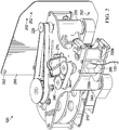
- winch system 120 may comprise a main reel 210, a first motor 220, a set of pinch rollers 230 (i.e., 230a-b), and a second motor 240.
- winch system 120 is the component responsible for reeling payload line 130 in and out.
- reeling payload line 130 out refers to increasing the length of payload line 130 extending from aircraft 110
- reeling payload line 130 in refers to decreasing the length of payload line 130 extending from aircraft 110.
- Main reel 210 may be a spool about which payload line 130 is wound.
- payload line 130 may be coupled to main reel 210 at a first end 130a and all or a portion of payload line 130 may be wound about main reel 210.
- Second end 130b of payload line 130 may be configured to be spooled onto and off of main reel 210. This is best illustrated in FIGURE 3 wherein payload line 130 is wound about main reel 110 and second end 130b of payload line 130 is threaded through an aperture 330 in shaft 320.
- payload line 130 is spooled onto and off of main reel 210 by turning main reel 210.
- turning main reel 210 in a first direction may feed payload line 130 out and turning main reel 210 in a second direction may reel payload line 130 in.
- first motor 220 is operable to turn main reel 210 in both the first and the second direction.
- First motor 220 may receive instructions to turn main reel 210 from one or more controllers of airborne payload control system 100.
- controller 150 of FIGURE 1 may send instructions to first motor 220 to turn main reel 210 in the first direction and, in response, first motor 220 may turn main reel 210 in the first direction.
- winch system 120 may include pinch rollers 230.
- payload line 130 may be threaded between first pinch roller 230a and second pinch roller 230b.
- Pinch rollers 230 may be configured to maintain tension on payload line 130.
- tension on payload line 130 is maintained by keeping payload line taught between main reel 210 and pinch rollers 230. This may be achieved by turning pinch rollers 230 in the first and/or second direction.
- one or more pinch rollers 230 are rotated by second motor 240.
- Second motor 240 may be configured to turn one or more pinch rollers 230.
- second motor 240 may be configured to turn first pinch roller 230a but not second pinch roller 230b.
- Second motor 240 may be configured to turn one or more pinch rollers 230 in the first direction and/or the second direction.
- second motor 240 receives instructions from one or more controllers of airborne payload control system 100.
- controller 150 of FIGURE 1 may send instructions to second motor 240 to turn first pinch roller 230a in the first direction and, in response, second motor 240 may turn first pinch roller 230a in the first direction.
- one or more controllers of airborne payload control system 100 may send instructions to one or more of first motor 220 and second motor 240.
- controller 150 of FIGURE 1 may instruct second motor 240 to turn one or more pinch rollers 230 in the first direction (to feed payload line 130 out).
- controller 150 of FIGURE 1 may instruct first motor 230 to turn main reel 210 in the second direction (to reel payload line 130 in).
- controller(s) 150 may instruct motors 220 and 240 to turn main reel 210 and pinch rollers 230, respectively, at particular rates.
- such instructions may enable controller 150 to control the speed and/or length of payload line 130 and/or tension on payload line 130.
- Controller(s) 150 may send instructions to first motor 220 and second motor 240 that enable main reel 210 and pinch rollers 230 to cooperate to feed payload line 130 in and out. For example, in response to determining to feed payload line 130 in, controller 150 of FIGURE 1 may instruct first motor 230 to turn main reel 210 in the second direction and instruct second motor 220 to apply a braking function. As another example, in response to determining to feed payload line 130 out, controller 150 of FIGURE 1 may instruct second motor 240 to turn one or more pinch rollers 230 in the second direction and instruct first motor 220 to apply a braking function.
- Such instructions may permit payload line 130 to be reeled in and out while also keeping payload line 130 taught between main reel 210 and pinch roller 230 thus preventing payload line 130 from tangling (e.g., as may occur when reeling in payload line 130 at high speeds and not keeping payload line 130 taught).
- the instructions of controller(s) 150 to first motor 220 and/or second motor 240 may permit winch system 120 to maintain second end 130b of payload line 130 in a particular position (e.g., latitude, longitude, and altitude).
- Each of motors 220 and 240 may be associated with one or more optical encoders (not illustrated).
- the one or more optical encoders may be configured to detect information about payload line 130 and relay the information to one or more controllers of airborne payload control system 100 (e.g., controller 150).
- the information detected by an optical encoder may be used to determine the length of payload line 130 on main reel 210.
- controller 150 may provide instructions to one or more components of airborne payload control system 100 (e.g., first motor 220, second motor 240, etc.).
- controller 150 sends instructions to reduce the speed of second motor 240 while reeling out payload line 130.
- instructions from controller(s) 150 may be based on information received from line sensor 140.
- controller 150 may send instructions to one or more of first motor 220 and second motor 240.
- controller(s) 150 may use feedback from line sensor 140 to control the distance, velocity, acceleration, and/or jerk on payload line 130.
- the distance, velocity, acceleration, and/or jerk of payload line 130 is controlled to maintain a particular position (e.g., latitude, longitude, and altitude) of second end 130b of payload line 130 during the flight of aircraft 110.
- winch system 120 includes additional components.
- winch system 120 includes a mounting plate 250.
- Mounting plate 250 may be configured to mount winch system 120 to aircraft 110.
- mounting plate 250 includes apertures 252 configured to receive fasteners therethrough. Fasteners may be used to couple winch system 120 to aircraft 110.
- Winch system 120 may also include an eye 260.
- eye 260 is a plate comprising an aperture through which second end 130b of payload line 130 is threaded. Eye 260 may be configured to restrict movement of payload line 130. This may be desirable to limit movement of payload line 130 as it is reeled in and out by winch system 120.
- Winch system 120 may also include one or more servo motors (e.g., servo motors 270 and 310) that provide additional functionality.
- Servo motors 270 and 310 and the functionality they provide are best illustrated in FIGURE 3 .
- Servo motor 270 may be operable to move a locking bar 272 from a first position to a second position.
- main reel 210 may be turned in the first or the second direction when locking bar 272 is in the first position (unlocked position) and main reel 210 may be prevented from turning when locking bar 272 is in the second position (locked position).
- servo motor 270 is configured to receive instructions from one or more controllers of airborne payload control system 100 (e.g., controller 150 of FIGURE 1 ) and move locking bar 272 from the first position to the second position (or from the second position to the first position) upon receiving instructions to do so.
- controller 150 e.g., controller 150 of FIGURE 1
- servo motor 170 may push locking bar 272 into main reel 210, thereby preventing main reel 210 from turning.
- FIGURE 3 also illustrates servo motor 310.
- Servo motor 310 may be operable to move shaft 320.
- servo motor 310 may be operable to move shaft 320 from a first position to a second position.
- shaft 320 may include aperture 330 through which second end 130b of payload line 130 is threaded.
- moving shaft 320 from the first position to the second position causes payload line 130 to be distributed in a substantially even manner on main reel 210.
- distributing payload line 130 in a "substantially even manner" prevents payload line 130 from being lumped on the sides or in the center of main reel 210.
- winch system 120 may comprise any suitable component.
- This disclosure also contemplates a line cutting feature of winch system 120.
- this line cutting feature is performed using components described herein. Such feature may be performed at the direction of controller(s) 150.
- controller 150 may instruct servo motor 170 to move locking bar 272 into the locked position and, after locking bar 272 is positioned in the locked position, instruct second motor 240 to begin feeding line out, thus causing a friction cut of payload line 130.
- FIGURE 4 illustrates a method 400 of operation for airborne payload control system 100.
- Method 400 may be performed by one or more controllers of airborne payload control system 100.
- controller 150 of FIGURE 1 may perform method 400.
- a controller operable to perform method 400 may be a computer such as computer 600 of FIGURE 6 .
- Method 400 may be stored in a memory of controller (e.g., memory 620 of FIGURE 6 ).
- Method 400 may begin in step 405 and proceed to step 410.
- controller 150 may receive information about payload line 130.
- controller 150 may receive information about payload line 130 from line sensor 140.
- the information received by controller 150 may comprise one or more of: a position of payload line 130; a velocity of payload line 130; and an altitude of second end 130b of the payload line 130.
- line sensor 140 may detect any suitable information (e.g., information that would be helpful in maintaining a position of second end 130b of payload line 130).
- method 400 proceeds to step 420.
- controller 150 provides instructions to aircraft 110 and winch system 120 based on information received at step 410.
- the instructions provided by controller 150 at step 420 cause a position of second end 130b of payload line 130 to be maintained.
- controller 150 may provide instructions to an onboard avionic system operable to control one or more of the flight path, speed, orbit, and/or altitude of aircraft 110.
- Controller 150 may also provide instructions to one or more of first motor 220 and/or second motor 240.
- instructions to first motor 220 may include instructions regarding one or more of a direction of turning main reel 210, a speed at which to turn main reel 210, a tension on payload line 130, and an application of a braking functionality.
- Instructions to second motor 220 may include instructions regarding one or more of a direction of turning one or more pinch rollers 130, a speed of turning one or more pinch rollers 130, a tension on payload line 130, and an application of a braking functionality. Controller 150 may also provide instructions to one or more servo motors of winch system 120. For example, controller 150 may instruct servo motor 270 to move locking bar 272 from a first position to a second position. As another example, controller 150 may instruct servo motor 310 to move shaft 320 from a first position to a second position. In some embodiments, after performing step 420, method 400 proceeds to an end step 425.
- FIGURE 5 illustrates a method 500 of operation for winch system 120.
- Method 500 may be performed by one or more controllers of airborne payload control system 100.
- controller 150 of FIGURE 1 may perform method 500.
- a controller operable to perform method 500 may be a computer such as computer 600 of FIGURE 6 .
- Method 500 may be stored in a memory of controller (e.g., memory 620 of FIGURE 6 ).
- Method 500 may begin in step 505 and proceed to step 510.
- one or more of first motor 220 and second motor 240 receives instructions to spool payload line 130.
- the received instructions instruct first motor 220 and/or second motor 240 to spool payload line 130 in or out.
- payload line 130 may be spooled out by turning one or more of main reel 210 and/or pinch rollers 130 in the first direction and payload line 130 may be spooled in by turning one or more of main reel 210 and/or pinch rollers 130 in the second direction.
- payload line 130 is spooled out by instructing first motor 220 to perform a braking function and instructing second motor 240 to turn in the first direction. In some other embodiments, payload line 130 is spooled in by instructing first motor 220 to turn in the second direction and instructing second motor 240 to apply a braking function. In some embodiments, the received instructions instruct first motor 220 and/or second motor 240 to operate at a particular speed. In other embodiments, the received instructions instruct first motor 220 and/or second motor 240 to pull payload line 130 taught.
- first motor 220 and/or second motor 240 receives instructions to spool payload line 130, the method 500 proceeds to step 520.
- first motor 220 and/or second motor 240 operate based on the instructions received at step 510.
- first motor 220 may apply a braking function in response to receiving an instruction to perform a braking function.
- second motor 240 may begin turning pinch roller 230a at a particular rate (e.g., 150 rpm) in the first direction in order to increase the length of payload line 130.
- the instructions may be implemented serially or simultaneously.
- implementing the instructions received at step 510 cause the position of second end 130b of payload line 130 (e.g., latitude, longitude, and altitude) to be maintained.
- FIGURE 6 illustrates an example computer system 600.
- Computer system 600 may be utilized by airborne payload control system 100 of FIGURE 1 .
- controller 150 of FIGURE 1 may be a computer system 600.
- one or more computer systems 600 perform one or more steps of one or more methods described or illustrated herein.
- one or more computer systems 600 provide functionality described or illustrated herein.
- software running on one or more computer systems 600 performs one or more steps of one or more methods described or illustrated herein or provides functionality described or illustrated herein.
- Particular embodiments include one or more portions of one or more computer systems 600.
- reference to a computer system may encompass a computing device, and vice versa, where appropriate.
- reference to a computer system may encompass one or more computer systems, where appropriate.
- computer system 600 may be an embedded computer system, a system-on-chip (SOC), a single-board computer system (SBC) (such as, for example, a computer-on-module (COM) or system-on-module (SOM)), a desktop computer system, a laptop or notebook computer system, an interactive kiosk, a mainframe, a mesh of computer systems, a mobile telephone, a personal digital assistant (PDA), a server, a tablet computer system, or a combination of two or more of these.
- SOC system-on-chip
- SBC single-board computer system
- COM computer-on-module
- SOM system-on-module
- computer system 600 may include one or more computer systems 600; be unitary or distributed; span multiple locations; span multiple machines; span multiple data centers; or reside in a cloud, which may include one or more cloud components in one or more networks.
- one or more computer systems 600 may perform without substantial spatial or temporal limitation one or more steps of one or more methods described or illustrated herein.
- one or more computer systems 600 may perform in real time or in batch mode one or more steps of one or more methods described or illustrated herein.
- One or more computer systems 600 may perform at different times or at different locations one or more steps of one or more methods described or illustrated herein, where appropriate.
- computer system 600 includes a processor 610, memory 620, storage 630, an input/output (I/O) interface 640, a communication interface 650, and a bus 660.
- I/O input/output
- this disclosure describes and illustrates a particular computer system having a particular number of particular components in a particular arrangement, this disclosure contemplates any suitable computer system having any suitable number of any suitable components in any suitable arrangement.
- processor 610 includes hardware for executing instructions, such as those making up a computer program.
- processor 610 may retrieve (or fetch) the instructions from an internal register, an internal cache, memory 620, or storage 630; decode and execute them; and then write one or more results to an internal register, an internal cache, memory 620, or storage 630.
- processor 610 may include one or more internal caches for data, instructions, or addresses. This disclosure contemplates processor 610 including any suitable number of any suitable internal caches, where appropriate.
- processor 610 may include one or more instruction caches, one or more data caches, and one or more translation lookaside buffers (TLBs).
- TLBs translation lookaside buffers
- Instructions in the instruction caches may be copies of instructions in memory 620 or storage 630, and the instruction caches may speed up retrieval of those instructions by processor 610.
- Data in the data caches may be copies of data in memory 620 or storage 630 for instructions executing at processor 610 to operate on; the results of previous instructions executed at processor 610 for access by subsequent instructions executing at processor 610 or for writing to memory 620 or storage 630; or other suitable data.
- the data caches may speed up read or write operations by processor 610.
- the TLBs may speed up virtual-address translation for processor 610.
- processor 610 may include one or more internal registers for data, instructions, or addresses. This disclosure contemplates processor 610 including any suitable number of any suitable internal registers, where appropriate. Where appropriate, processor 610 may include one or more arithmetic logic units (ALUs); be a multi-core processor; or include one or more processors 610.
- memory 620 includes main memory for storing instructions for processor 610 to execute or data for processor 610 to operate on.
- computer system 600 may load instructions from storage 630 or another source (such as, for example, another computer system 600) to memory 620.
- Processor 610 may then load the instructions from memory 620 to an internal register or internal cache.
- processor 610 may retrieve the instructions from the internal register or internal cache and decode them.
- processor 610 may write one or more results (which may be intermediate or final results) to the internal register or internal cache.
- Processor 610 may then write one or more of those results to memory 620.
- processor 610 executes only instructions in one or more internal registers or internal caches or in memory 620 (as opposed to storage 630 or elsewhere) and operates only on data in one or more internal registers or internal caches or in memory 620 (as opposed to storage 630 or elsewhere).
- One or more memory buses (which may each include an address bus and a data bus) may couple processor 610 to memory 620.
- Bus 660 may include one or more memory buses, as described below.
- one or more memory management units reside between processor 610 and memory 620 and facilitate accesses to memory 620 requested by processor 610.
- memory 620 includes random access memory (RAM).
- This RAM may be volatile memory, where appropriate Where appropriate, this RAM may be dynamic RAM (DRAM) or static RAM (SRAM). Moreover, where appropriate, this RAM may be single-ported or multi-ported RAM. This disclosure contemplates any suitable RAM.
- Memory 620 may include one or more memories 620, where appropriate. Although this disclosure describes and illustrates particular memory, this disclosure contemplates any suitable memory.
- storage 630 includes mass storage for data or instructions.
- storage 630 may include a hard disk drive (HDD), a floppy disk drive, flash memory, an optical disc, a magneto-optical disc, magnetic tape, or a Universal Serial Bus (USB) drive or a combination of two or more of these.
- HDD hard disk drive
- floppy disk drive flash memory
- optical disc an optical disc
- magneto-optical disc magnetic tape
- USB Universal Serial Bus
- Storage 630 may include removable or non-removable (or fixed) media, where appropriate.
- Storage 630 may be internal or external to computer system 600, where appropriate.
- storage 630 is non-volatile, solid-state memory.
- storage 630 includes read-only memory (ROM).
- this ROM may be mask-programmed ROM, programmable ROM (PROM), erasable PROM (EPROM), electrically erasable PROM (EEPROM), electrically alterable ROM (EAROM), or flash memory or a combination of two or more of these.
- This disclosure contemplates mass storage 630 taking any suitable physical form.
- Storage 630 may include one or more storage control units facilitating communication between processor 610 and storage 630, where appropriate. Where appropriate, storage 630 may include one or more storages 630. Although this disclosure describes and illustrates particular storage, this disclosure contemplates any suitable storage.
- I/O interface 640 includes hardware, software, or both, providing one or more interfaces for communication between computer system 600 and one or more I/O devices.
- Computer system 600 may include one or more of these I/O devices, where appropriate.
- One or more of these I/O devices may enable communication between a person and computer system 600.
- an I/O device may include a keyboard, keypad, microphone, monitor, mouse, printer, scanner, speaker, still camera, stylus, tablet, touch screen, trackball, video camera, another suitable I/O device or a combination of two or more of these.
- An I/O device may include one or more sensors. This disclosure contemplates any suitable I/O devices and any suitable I/O interfaces 640 for them.
- I/O interface 640 may include one or more device or software drivers enabling processor 610 to drive one or more of these I/O devices.
- I/O interface 640 may include one or more I/O interfaces 640, where appropriate. Although this disclosure describes and illustrates a particular I/O interface, this disclosure contemplates any suitable I/O interface.
- communication interface 650 includes hardware, software, or both providing one or more interfaces for communication (such as, for example, packet-based communication) between computer system 600 and one or more other computer systems 600 or one or more networks.
- communication interface 650 may include a network interface controller (NIC) or network adapter for communicating with an Ethernet or other wire-based network or a wireless NIC (WNIC) or wireless adapter for communicating with a wireless network, such as a WI-FI network.
- NIC network interface controller
- WNIC wireless NIC
- WI-FI network wireless network
- computer system 600 may communicate with an ad hoc network, a personal area network (PAN), a local area network (LAN), a wide area network (WAN), a metropolitan area network (MAN), or one or more portions of the Internet or a combination of two or more of these.
- PAN personal area network
- LAN local area network
- WAN wide area network
- MAN metropolitan area network
- computer system 600 may communicate with a wireless PAN (WPAN) (such as, for example, a BLUETOOTH WPAN), a WI-FI network, a WI-MAX network, a cellular telephone network (such as, for example, a Global System for Mobile Communications (GSM) network), or other suitable wireless network or a combination of two or more of these.
- WPAN wireless PAN
- WI-FI wireless personal area network
- WI-MAX wireless personal area network
- WI-MAX wireless personal area network
- cellular telephone network such as, for example, a Global System for Mobile Communications (GSM) network
- GSM Global System
- bus 660 includes hardware, software, or both coupling components of computer system 600 to each other.
- bus 660 may include an Accelerated Graphics Port (AGP) or other graphics bus, an Enhanced Industry Standard Architecture (EISA) bus, a front-side bus (FSB), a HYPERTRANSPORT (HT) interconnect, an Industry Standard Architecture (ISA) bus, an INFINIBAND interconnect, a low-pin-count (LPC) bus, a memory bus, a Micro Channel Architecture (MCA) bus, a Peripheral Component Interconnect (PCI) bus, a PCI-Express (PCIe) bus, a serial advanced technology attachment (SATA) bus, a Video Electronics Standards Association local (VLB) bus, or another suitable bus or a combination of two or more of these.
- Bus 660 may include one or more buses 712, where appropriate.
- the components of computer system 600 may be integrated or separated. In some embodiments, components of computer system 600 may each be housed within a single chassis. The operations of computer system 600 may be performed by more, fewer, or other components. Additionally, operations of computer system 600 may be performed using any suitable logic that may comprise software, hardware, other logic, or any suitable combination of the preceding.
- a computer-readable non-transitory storage medium or media may include one or more semiconductor-based or other integrated circuits (ICs) (such, as for example, field-programmable gate arrays (FPGAs) or application-specific ICs (ASICs)), hard disk drives (HDDs), hybrid hard drives (HHDs), optical discs, optical disc drives (ODDs), magneto-optical discs, magneto-optical drives, floppy diskettes, floppy disk drives (FDDs), magnetic tapes, solid-state drives (SSDs), RAM-drives, SECURE DIGITAL cards or drives, any other suitable computer-readable non-transitory storage media, or any suitable combination of two or more of these, where appropriate.
- ICs such, as for example, field-programmable gate arrays (FPGAs) or application-specific ICs (ASICs)
- HDDs hard disk drives
- HHDs hybrid hard drives
- ODDs optical disc drives
- magneto-optical discs magneto-optical drives
- an apparatus or system or a component of an apparatus or system being adapted to, arranged to, capable of, configured to, enabled to, operable to, or operative to perform a particular function encompasses that apparatus, system, component, whether or not it or that particular function is activated, turned on, or unlocked, as long as that apparatus, system, or component is so adapted, arranged, capable, configured, enabled, operable, or operative.
Landscapes
- Engineering & Computer Science (AREA)
- Mechanical Engineering (AREA)
- Aviation & Aerospace Engineering (AREA)
- Control Of Position, Course, Altitude, Or Attitude Of Moving Bodies (AREA)
- Toys (AREA)
- Control And Safety Of Cranes (AREA)
- Control Of Electric Motors In General (AREA)
Applications Claiming Priority (1)
| Application Number | Priority Date | Filing Date | Title |
|---|---|---|---|
| US15/444,686 US10519013B2 (en) | 2017-02-28 | 2017-02-28 | Winch system for an airborne payload control system |
Publications (2)
| Publication Number | Publication Date |
|---|---|
| EP3366636A1 true EP3366636A1 (fr) | 2018-08-29 |
| EP3366636B1 EP3366636B1 (fr) | 2024-04-03 |
Family
ID=61282995
Family Applications (1)
| Application Number | Title | Priority Date | Filing Date |
|---|---|---|---|
| EP18158341.0A Active EP3366636B1 (fr) | 2017-02-28 | 2018-02-23 | Système de treuil destiné à un système de commande de charge utile embarqué |
Country Status (4)
| Country | Link |
|---|---|
| US (1) | US10519013B2 (fr) |
| EP (1) | EP3366636B1 (fr) |
| CN (1) | CN108502759B (fr) |
| TW (1) | TWI770129B (fr) |
Cited By (1)
| Publication number | Priority date | Publication date | Assignee | Title |
|---|---|---|---|---|
| US20180244509A1 (en) * | 2017-02-28 | 2018-08-30 | Lockheed Martin Corporation | Winch system for an airborne payload control system |
Families Citing this family (33)
| Publication number | Priority date | Publication date | Assignee | Title |
|---|---|---|---|---|
| US9359075B1 (en) | 2013-04-02 | 2016-06-07 | Hood Technology Corporation | Helicopter-mediated system and method for launching and retrieving an aircraft |
| US10696420B2 (en) | 2016-08-17 | 2020-06-30 | Hood Technology Corporation | Rotorcraft-assisted system and method for launching and retrieving a fixed-wing aircraft into and from free flight |
| US11505330B2 (en) * | 2016-08-20 | 2022-11-22 | Modern Technology Solutions, Inc. | Refueling system and systems with end effectors |
| US11312492B1 (en) | 2017-11-09 | 2022-04-26 | Hood Technology Corporation | Rotorcraft-assisted systems and methods for launching and retrieving a fixed-wing aircraft into and from free flight |
| DE202019006130U1 (de) | 2018-02-08 | 2025-04-14 | Vita Inclinata Ip Holdings Llc | Laststabilisationssystem |
| US12304779B2 (en) | 2018-02-08 | 2025-05-20 | Vita Inclinata Ip Holdings Llc | On-board power and remote power for suspended load control apparatuses, systems, and methods |
| US12246952B2 (en) | 2018-02-08 | 2025-03-11 | Vita Inclintata IP Holdings LLC | Hoist and deployable equipment apparatus, system, and method |
| US12434813B2 (en) | 2018-02-08 | 2025-10-07 | Vita Inclinata Ip Holdings Llc | Bidirectional thrust apparatus, system and method |
| US11945697B2 (en) | 2018-02-08 | 2024-04-02 | Vita Inclinata Ip Holdings Llc | Multiple remote control for suspended load control equipment apparatus, system, and method |
| US11209836B1 (en) | 2018-02-08 | 2021-12-28 | Vita Inclinata Technologies, Inc. | Long line loiter apparatus, system, and method |
| US11142316B2 (en) | 2018-02-08 | 2021-10-12 | Vita Inclinata Technologies, Inc. | Control of drone-load system method, system, and apparatus |
| US10934142B2 (en) * | 2018-02-27 | 2021-03-02 | Hall Labs Llc | Motor-driven fairlead for assisting spooling or unspooling from a winch |
| US12065225B2 (en) * | 2018-05-02 | 2024-08-20 | Modern Technology Solutions, Inc. | Rapid aerial extraction systems |
| US11026502B1 (en) * | 2018-06-11 | 2021-06-08 | Francisco Erold | Portable electronic device leash and associated use thereof |
| WO2020125888A1 (fr) * | 2018-12-21 | 2020-06-25 | Vestas Wind Systems A/S | Dispositif de commande de charge utile |
| US11391650B2 (en) * | 2019-04-10 | 2022-07-19 | Fairweather IT LLC | Method and apparatus for performing water sampling with an unmanned aerial vehicle |
| US11834305B1 (en) | 2019-04-12 | 2023-12-05 | Vita Inclinata Ip Holdings Llc | Apparatus, system, and method to control torque or lateral thrust applied to a load suspended on a suspension cable |
| WO2025122161A1 (fr) | 2023-12-04 | 2025-06-12 | Vita Inclinata Ip Holdings Llc | Appareil, système et procédé de commande de couple ou de poussée latérale appliqué à une charge suspendue sur un câble de suspension |
| US11618566B1 (en) | 2019-04-12 | 2023-04-04 | Vita Inclinata Technologies, Inc. | State information and telemetry for suspended load control equipment apparatus, system, and method |
| US11542129B2 (en) * | 2019-06-10 | 2023-01-03 | Goodrich Corporation | Dual bus and hardwire architecture for high reliability control of helicopter hoist |
| US11492117B2 (en) | 2019-06-10 | 2022-11-08 | Goodrich Corporation | Dual bus architecture for high reliability control of helicopter hoist |
| CN114423703B (zh) | 2019-07-21 | 2025-06-24 | 维塔因克莱纳塔知识产权控股有限公司 | 提升机和可展开设备、装置、系统和方法 |
| US11697499B2 (en) * | 2019-08-22 | 2023-07-11 | Sony Corporation | Method for transporting a rescue device from an aerial vehicle to a person to be rescued, rescue system for rescuing a person to be rescued, and unmanned aerial vehicle for transporting a rescue device from an aerial vehicle to a person to be rescued |
| US11932393B2 (en) * | 2019-09-03 | 2024-03-19 | Rakuten Group, Inc. | Unmanned aerial device, load-lowering device, and load transport method |
| EP4065468B1 (fr) | 2019-11-25 | 2025-05-07 | Vita Inclinata IP Holdings LLC | Procédé et appareil pour le contrôle d'une charge suspendue |
| US11807367B2 (en) * | 2019-12-02 | 2023-11-07 | United Parcel Service Of America, Inc. | Multiple hoist delivery system for delivering parcels using unmanned aerial vehicles |
| CN112249337B (zh) * | 2020-10-15 | 2021-12-17 | 重庆工程职业技术学院 | 一种无人机吊运模块 |
| US20240239485A1 (en) * | 2021-09-17 | 2024-07-18 | Jetzero, Inc. | Blended wing body aircraft with a fuel cell and method of use |
| US12539967B2 (en) * | 2022-04-14 | 2026-02-03 | Aero Velocity Inc. | Unmanned aerial vehicle delivery systems |
| US12522354B2 (en) | 2022-04-28 | 2026-01-13 | Hornet Acquisitionco, Llc | Augmented hoist cable cut algorithm |
| JP7812585B2 (ja) | 2022-04-29 | 2026-02-10 | ビタ インクリナータ アイピー ホールディングス エルエルシー | 機械学習による不動産物の検出および解析装置、システム、及び方法 |
| US12377995B2 (en) * | 2022-11-22 | 2025-08-05 | Embraer S.A. | Aircraft tail mounted fuel cell power train and thermal management systems |
| WO2025207805A1 (fr) * | 2024-03-27 | 2025-10-02 | Kyte Dynamics, Inc. | Système de véhicule aérien suspendu doté de plusieurs treuils |
Citations (4)
| Publication number | Priority date | Publication date | Assignee | Title |
|---|---|---|---|---|
| JPH0453790U (fr) * | 1990-09-10 | 1992-05-08 | ||
| EP0571207A1 (fr) * | 1992-05-20 | 1993-11-24 | SUPERWINCH LIMITED (Reg.No. 2708737) | Treuil |
| GB2434352A (en) * | 2006-01-20 | 2007-07-25 | Lgh Group Plc | Vehicle mounted twin capstan winch |
| US20160059963A1 (en) * | 2014-08-28 | 2016-03-03 | Google Inc. | Payload-Release Device and Operation Thereof |
Family Cites Families (26)
| Publication number | Priority date | Publication date | Assignee | Title |
|---|---|---|---|---|
| US2295537A (en) | 1940-05-29 | 1942-09-15 | William H Woodin Jr | Method and apparatus for pickup and delivery by aircraft in flight |
| US2991959A (en) * | 1958-05-13 | 1961-07-11 | Rizzo Samuel | Electro-mechanical winch control system |
| US3389880A (en) | 1966-06-21 | 1968-06-25 | Recovery Res Systems Inc | Parachute system for mid-air load recovery |
| US3466013A (en) * | 1967-11-08 | 1969-09-09 | Abex Corp | Winch cable anti-slack unit |
| US4416436A (en) | 1981-10-23 | 1983-11-22 | Lockheed Corporation | Aerial transport of payloads with vertical pick up and delivery |
| US4730194A (en) | 1985-06-20 | 1988-03-08 | Westinghouse Electric Corp. | Airborne transmitting antenna and method for deploying same |
| JP2903250B2 (ja) * | 1990-06-22 | 1999-06-07 | 旭電化工業株式会社 | 感熱記録材料 |
| GB9929102D0 (en) * | 1999-12-10 | 2000-02-02 | Electric Drive Systems S A | Maritime reeling system |
| US6824102B2 (en) | 2003-03-10 | 2004-11-30 | Haggard Roy A | Parafoil mid-air retrieval |
| US7111803B2 (en) * | 2004-04-16 | 2006-09-26 | Pelican Point Seafood, Inc. | Cable winch system |
| JP2007075473A (ja) * | 2005-09-16 | 2007-03-29 | Toshintec Kk | 車椅子乗降用電動ウィンチ |
| US8231083B2 (en) | 2007-10-18 | 2012-07-31 | The Boeing Company | System and methods for airborne launch and recovery of aircraft |
| US20110006151A1 (en) | 2008-06-20 | 2011-01-13 | Beard Randal W | Aerial recovery of small and micro air vehicles |
| JP5503650B2 (ja) * | 2008-07-18 | 2014-05-28 | ベースロード・エナジー・インコーポレイテッド | 飛行型発電機用テザー処理システムおよび方法 |
| US8038090B2 (en) | 2009-03-19 | 2011-10-18 | Aurora Flight Sciences Corporation | System and method for the retrieval of a smaller unmanned aerial vehicle by a larger unmanned aerial vehicle |
| US8720811B2 (en) * | 2011-03-07 | 2014-05-13 | Stoneage, Inc. | Apparatus and method for storing and dispensing a pressure hose |
| FR2974786B1 (fr) | 2011-05-03 | 2013-11-22 | Eurocopter France | Dispositif de largage et de recuperation d'un drone, et aeronef associe |
| US9359075B1 (en) | 2013-04-02 | 2016-06-07 | Hood Technology Corporation | Helicopter-mediated system and method for launching and retrieving an aircraft |
| US9346547B2 (en) * | 2013-08-26 | 2016-05-24 | Google Inc. | Mechanisms for lowering a payload to the ground from a UAV |
| US9211951B2 (en) * | 2013-12-10 | 2015-12-15 | Google Inc. | Systems and apparatus for tether termination mount for tethered aerial vehicles |
| US9475589B2 (en) * | 2013-12-20 | 2016-10-25 | Google Inc. | Systems and apparatus for winch drum mechanism |
| US9650157B2 (en) * | 2014-06-30 | 2017-05-16 | X Development Llc | Drive mechanisms for use in controlling rotation and twist of a tether |
| CN104330279A (zh) * | 2014-10-24 | 2015-02-04 | 成都好飞机器人科技有限公司 | 多旋翼无人机 |
| JP6404694B2 (ja) * | 2014-12-05 | 2018-10-10 | 株式会社神戸製鋼所 | 電動ウインチ装置及び移動式クレーン |
| US10384782B2 (en) * | 2017-02-28 | 2019-08-20 | Lockheed Martin Corporation | Airborne payload control system |
| US10519013B2 (en) * | 2017-02-28 | 2019-12-31 | Lockheed Martin Corporation | Winch system for an airborne payload control system |
-
2017
- 2017-02-28 US US15/444,686 patent/US10519013B2/en active Active
-
2018
- 2018-02-23 EP EP18158341.0A patent/EP3366636B1/fr active Active
- 2018-02-27 TW TW107106688A patent/TWI770129B/zh active
- 2018-02-28 CN CN201810164245.6A patent/CN108502759B/zh active Active
Patent Citations (4)
| Publication number | Priority date | Publication date | Assignee | Title |
|---|---|---|---|---|
| JPH0453790U (fr) * | 1990-09-10 | 1992-05-08 | ||
| EP0571207A1 (fr) * | 1992-05-20 | 1993-11-24 | SUPERWINCH LIMITED (Reg.No. 2708737) | Treuil |
| GB2434352A (en) * | 2006-01-20 | 2007-07-25 | Lgh Group Plc | Vehicle mounted twin capstan winch |
| US20160059963A1 (en) * | 2014-08-28 | 2016-03-03 | Google Inc. | Payload-Release Device and Operation Thereof |
Cited By (2)
| Publication number | Priority date | Publication date | Assignee | Title |
|---|---|---|---|---|
| US20180244509A1 (en) * | 2017-02-28 | 2018-08-30 | Lockheed Martin Corporation | Winch system for an airborne payload control system |
| US10519013B2 (en) * | 2017-02-28 | 2019-12-31 | Lockheed Martin Corporation | Winch system for an airborne payload control system |
Also Published As
| Publication number | Publication date |
|---|---|
| US10519013B2 (en) | 2019-12-31 |
| TWI770129B (zh) | 2022-07-11 |
| CN108502759B (zh) | 2022-01-21 |
| TW201838876A (zh) | 2018-11-01 |
| US20180244509A1 (en) | 2018-08-30 |
| CN108502759A (zh) | 2018-09-07 |
| EP3366636B1 (fr) | 2024-04-03 |
Similar Documents
| Publication | Publication Date | Title |
|---|---|---|
| US10519013B2 (en) | Winch system for an airborne payload control system | |
| US10384782B2 (en) | Airborne payload control system | |
| US11667397B2 (en) | System and method of blade-tip facilitated aircraft capture | |
| EP3835202B1 (fr) | Procédés et appareil de récupération d'aéronefs sans pilote (uav) à l'aide de cerfs-volants | |
| EP3468871B1 (fr) | Appareils de libération d'une charge utile à partir d'un câble aérien | |
| US12612776B2 (en) | Unmanned aerial vehicle | |
| US9671791B1 (en) | Managing unmanned vehicles | |
| US7219856B2 (en) | UAV recovery system | |
| US20230182781A1 (en) | Application-based controls for wheelchair-accessible autonomous vehicle | |
| CN110738872A (zh) | 用于空中交通工具的飞行控制系统和相关方法 | |
| US20190392717A1 (en) | Orchestration in heterogeneous drone swarms | |
| US10807715B2 (en) | Method for automatic drone package pickup | |
| US10012999B2 (en) | Exploiting or avoiding air drag for an aerial vehicle | |
| US11267581B2 (en) | Unmanned aerial vehicle (UAV) launch and recovery | |
| US20200062388A1 (en) | Take off and landing system for drone for use with an autonomous vehicle | |
| US20200110424A1 (en) | Geofencing of unmanned aerial vehicles | |
| CN115202270A (zh) | 一种机载负载控制系统及控制方法 | |
| EP4079642B1 (fr) | Mâts rotatifs pour récupérer des avions avec des cerfs-volants | |
| US12515794B2 (en) | UAV having a rotatable cargo bay |
Legal Events
| Date | Code | Title | Description |
|---|---|---|---|
| PUAI | Public reference made under article 153(3) epc to a published international application that has entered the european phase |
Free format text: ORIGINAL CODE: 0009012 |
|
| STAA | Information on the status of an ep patent application or granted ep patent |
Free format text: STATUS: THE APPLICATION HAS BEEN PUBLISHED |
|
| AK | Designated contracting states |
Kind code of ref document: A1 Designated state(s): AL AT BE BG CH CY CZ DE DK EE ES FI FR GB GR HR HU IE IS IT LI LT LU LV MC MK MT NL NO PL PT RO RS SE SI SK SM TR |
|
| AX | Request for extension of the european patent |
Extension state: BA ME |
|
| STAA | Information on the status of an ep patent application or granted ep patent |
Free format text: STATUS: REQUEST FOR EXAMINATION WAS MADE |
|
| 17P | Request for examination filed |
Effective date: 20190219 |
|
| RBV | Designated contracting states (corrected) |
Designated state(s): AL AT BE BG CH CY CZ DE DK EE ES FI FR GB GR HR HU IE IS IT LI LT LU LV MC MK MT NL NO PL PT RO RS SE SI SK SM TR |
|
| STAA | Information on the status of an ep patent application or granted ep patent |
Free format text: STATUS: EXAMINATION IS IN PROGRESS |
|
| 17Q | First examination report despatched |
Effective date: 20190715 |
|
| RIC1 | Information provided on ipc code assigned before grant |
Ipc: B64D 1/22 20060101ALI20230727BHEP Ipc: B64D 1/08 20060101ALI20230727BHEP Ipc: B64F 1/08 20060101ALI20230727BHEP Ipc: B66D 1/74 20060101AFI20230727BHEP |
|
| GRAP | Despatch of communication of intention to grant a patent |
Free format text: ORIGINAL CODE: EPIDOSNIGR1 |
|
| STAA | Information on the status of an ep patent application or granted ep patent |
Free format text: STATUS: GRANT OF PATENT IS INTENDED |
|
| INTG | Intention to grant announced |
Effective date: 20231011 |
|
| GRAS | Grant fee paid |
Free format text: ORIGINAL CODE: EPIDOSNIGR3 |
|
| P01 | Opt-out of the competence of the unified patent court (upc) registered |
Effective date: 20240109 |
|
| GRAA | (expected) grant |
Free format text: ORIGINAL CODE: 0009210 |
|
| STAA | Information on the status of an ep patent application or granted ep patent |
Free format text: STATUS: THE PATENT HAS BEEN GRANTED |
|
| AK | Designated contracting states |
Kind code of ref document: B1 Designated state(s): AL AT BE BG CH CY CZ DE DK EE ES FI FR GB GR HR HU IE IS IT LI LT LU LV MC MK MT NL NO PL PT RO RS SE SI SK SM TR |
|
| REG | Reference to a national code |
Ref country code: GB Ref legal event code: FG4D |
|
| REG | Reference to a national code |
Ref country code: CH Ref legal event code: EP |
|
| REG | Reference to a national code |
Ref country code: IE Ref legal event code: FG4D |
|
| REG | Reference to a national code |
Ref country code: DE Ref legal event code: R096 Ref document number: 602018067391 Country of ref document: DE |
|
| REG | Reference to a national code |
Ref country code: LT Ref legal event code: MG9D |
|
| REG | Reference to a national code |
Ref country code: NL Ref legal event code: MP Effective date: 20240403 |
|
| REG | Reference to a national code |
Ref country code: AT Ref legal event code: MK05 Ref document number: 1672131 Country of ref document: AT Kind code of ref document: T Effective date: 20240403 |
|
| PG25 | Lapsed in a contracting state [announced via postgrant information from national office to epo] |
Ref country code: NL Free format text: LAPSE BECAUSE OF FAILURE TO SUBMIT A TRANSLATION OF THE DESCRIPTION OR TO PAY THE FEE WITHIN THE PRESCRIBED TIME-LIMIT Effective date: 20240403 |
|
| PG25 | Lapsed in a contracting state [announced via postgrant information from national office to epo] |
Ref country code: NL Free format text: LAPSE BECAUSE OF FAILURE TO SUBMIT A TRANSLATION OF THE DESCRIPTION OR TO PAY THE FEE WITHIN THE PRESCRIBED TIME-LIMIT Effective date: 20240403 |
|
| PG25 | Lapsed in a contracting state [announced via postgrant information from national office to epo] |
Ref country code: IS Free format text: LAPSE BECAUSE OF FAILURE TO SUBMIT A TRANSLATION OF THE DESCRIPTION OR TO PAY THE FEE WITHIN THE PRESCRIBED TIME-LIMIT Effective date: 20240803 |
|
| PG25 | Lapsed in a contracting state [announced via postgrant information from national office to epo] |
Ref country code: BG Free format text: LAPSE BECAUSE OF FAILURE TO SUBMIT A TRANSLATION OF THE DESCRIPTION OR TO PAY THE FEE WITHIN THE PRESCRIBED TIME-LIMIT Effective date: 20240403 |
|
| PG25 | Lapsed in a contracting state [announced via postgrant information from national office to epo] |
Ref country code: HR Free format text: LAPSE BECAUSE OF FAILURE TO SUBMIT A TRANSLATION OF THE DESCRIPTION OR TO PAY THE FEE WITHIN THE PRESCRIBED TIME-LIMIT Effective date: 20240403 Ref country code: FI Free format text: LAPSE BECAUSE OF FAILURE TO SUBMIT A TRANSLATION OF THE DESCRIPTION OR TO PAY THE FEE WITHIN THE PRESCRIBED TIME-LIMIT Effective date: 20240403 |
|
| PG25 | Lapsed in a contracting state [announced via postgrant information from national office to epo] |
Ref country code: GR Free format text: LAPSE BECAUSE OF FAILURE TO SUBMIT A TRANSLATION OF THE DESCRIPTION OR TO PAY THE FEE WITHIN THE PRESCRIBED TIME-LIMIT Effective date: 20240704 |
|
| PG25 | Lapsed in a contracting state [announced via postgrant information from national office to epo] |
Ref country code: PT Free format text: LAPSE BECAUSE OF FAILURE TO SUBMIT A TRANSLATION OF THE DESCRIPTION OR TO PAY THE FEE WITHIN THE PRESCRIBED TIME-LIMIT Effective date: 20240805 |
|
| PG25 | Lapsed in a contracting state [announced via postgrant information from national office to epo] |
Ref country code: ES Free format text: LAPSE BECAUSE OF FAILURE TO SUBMIT A TRANSLATION OF THE DESCRIPTION OR TO PAY THE FEE WITHIN THE PRESCRIBED TIME-LIMIT Effective date: 20240403 |
|
| PG25 | Lapsed in a contracting state [announced via postgrant information from national office to epo] |
Ref country code: CZ Free format text: LAPSE BECAUSE OF FAILURE TO SUBMIT A TRANSLATION OF THE DESCRIPTION OR TO PAY THE FEE WITHIN THE PRESCRIBED TIME-LIMIT Effective date: 20240403 |
|
| PG25 | Lapsed in a contracting state [announced via postgrant information from national office to epo] |
Ref country code: AT Free format text: LAPSE BECAUSE OF FAILURE TO SUBMIT A TRANSLATION OF THE DESCRIPTION OR TO PAY THE FEE WITHIN THE PRESCRIBED TIME-LIMIT Effective date: 20240403 |
|
| PG25 | Lapsed in a contracting state [announced via postgrant information from national office to epo] |
Ref country code: PL Free format text: LAPSE BECAUSE OF FAILURE TO SUBMIT A TRANSLATION OF THE DESCRIPTION OR TO PAY THE FEE WITHIN THE PRESCRIBED TIME-LIMIT Effective date: 20240403 |
|
| PG25 | Lapsed in a contracting state [announced via postgrant information from national office to epo] |
Ref country code: LV Free format text: LAPSE BECAUSE OF FAILURE TO SUBMIT A TRANSLATION OF THE DESCRIPTION OR TO PAY THE FEE WITHIN THE PRESCRIBED TIME-LIMIT Effective date: 20240403 |
|
| PG25 | Lapsed in a contracting state [announced via postgrant information from national office to epo] |
Ref country code: PT Free format text: LAPSE BECAUSE OF FAILURE TO SUBMIT A TRANSLATION OF THE DESCRIPTION OR TO PAY THE FEE WITHIN THE PRESCRIBED TIME-LIMIT Effective date: 20240805 Ref country code: PL Free format text: LAPSE BECAUSE OF FAILURE TO SUBMIT A TRANSLATION OF THE DESCRIPTION OR TO PAY THE FEE WITHIN THE PRESCRIBED TIME-LIMIT Effective date: 20240403 Ref country code: NO Free format text: LAPSE BECAUSE OF FAILURE TO SUBMIT A TRANSLATION OF THE DESCRIPTION OR TO PAY THE FEE WITHIN THE PRESCRIBED TIME-LIMIT Effective date: 20240703 Ref country code: LV Free format text: LAPSE BECAUSE OF FAILURE TO SUBMIT A TRANSLATION OF THE DESCRIPTION OR TO PAY THE FEE WITHIN THE PRESCRIBED TIME-LIMIT Effective date: 20240403 Ref country code: IS Free format text: LAPSE BECAUSE OF FAILURE TO SUBMIT A TRANSLATION OF THE DESCRIPTION OR TO PAY THE FEE WITHIN THE PRESCRIBED TIME-LIMIT Effective date: 20240803 Ref country code: HR Free format text: LAPSE BECAUSE OF FAILURE TO SUBMIT A TRANSLATION OF THE DESCRIPTION OR TO PAY THE FEE WITHIN THE PRESCRIBED TIME-LIMIT Effective date: 20240403 Ref country code: GR Free format text: LAPSE BECAUSE OF FAILURE TO SUBMIT A TRANSLATION OF THE DESCRIPTION OR TO PAY THE FEE WITHIN THE PRESCRIBED TIME-LIMIT Effective date: 20240704 Ref country code: FI Free format text: LAPSE BECAUSE OF FAILURE TO SUBMIT A TRANSLATION OF THE DESCRIPTION OR TO PAY THE FEE WITHIN THE PRESCRIBED TIME-LIMIT Effective date: 20240403 Ref country code: ES Free format text: LAPSE BECAUSE OF FAILURE TO SUBMIT A TRANSLATION OF THE DESCRIPTION OR TO PAY THE FEE WITHIN THE PRESCRIBED TIME-LIMIT Effective date: 20240403 Ref country code: CZ Free format text: LAPSE BECAUSE OF FAILURE TO SUBMIT A TRANSLATION OF THE DESCRIPTION OR TO PAY THE FEE WITHIN THE PRESCRIBED TIME-LIMIT Effective date: 20240403 Ref country code: BG Free format text: LAPSE BECAUSE OF FAILURE TO SUBMIT A TRANSLATION OF THE DESCRIPTION OR TO PAY THE FEE WITHIN THE PRESCRIBED TIME-LIMIT Effective date: 20240403 Ref country code: AT Free format text: LAPSE BECAUSE OF FAILURE TO SUBMIT A TRANSLATION OF THE DESCRIPTION OR TO PAY THE FEE WITHIN THE PRESCRIBED TIME-LIMIT Effective date: 20240403 Ref country code: RS Free format text: LAPSE BECAUSE OF FAILURE TO SUBMIT A TRANSLATION OF THE DESCRIPTION OR TO PAY THE FEE WITHIN THE PRESCRIBED TIME-LIMIT Effective date: 20240703 |
|
| REG | Reference to a national code |
Ref country code: DE Ref legal event code: R097 Ref document number: 602018067391 Country of ref document: DE |
|
| PG25 | Lapsed in a contracting state [announced via postgrant information from national office to epo] |
Ref country code: DK Free format text: LAPSE BECAUSE OF FAILURE TO SUBMIT A TRANSLATION OF THE DESCRIPTION OR TO PAY THE FEE WITHIN THE PRESCRIBED TIME-LIMIT Effective date: 20240403 |
|
| PG25 | Lapsed in a contracting state [announced via postgrant information from national office to epo] |
Ref country code: EE Free format text: LAPSE BECAUSE OF FAILURE TO SUBMIT A TRANSLATION OF THE DESCRIPTION OR TO PAY THE FEE WITHIN THE PRESCRIBED TIME-LIMIT Effective date: 20240403 |
|
| PG25 | Lapsed in a contracting state [announced via postgrant information from national office to epo] |
Ref country code: RO Free format text: LAPSE BECAUSE OF FAILURE TO SUBMIT A TRANSLATION OF THE DESCRIPTION OR TO PAY THE FEE WITHIN THE PRESCRIBED TIME-LIMIT Effective date: 20240403 Ref country code: SK Free format text: LAPSE BECAUSE OF FAILURE TO SUBMIT A TRANSLATION OF THE DESCRIPTION OR TO PAY THE FEE WITHIN THE PRESCRIBED TIME-LIMIT Effective date: 20240403 |
|
| PG25 | Lapsed in a contracting state [announced via postgrant information from national office to epo] |
Ref country code: SM Free format text: LAPSE BECAUSE OF FAILURE TO SUBMIT A TRANSLATION OF THE DESCRIPTION OR TO PAY THE FEE WITHIN THE PRESCRIBED TIME-LIMIT Effective date: 20240403 |
|
| PG25 | Lapsed in a contracting state [announced via postgrant information from national office to epo] |
Ref country code: SM Free format text: LAPSE BECAUSE OF FAILURE TO SUBMIT A TRANSLATION OF THE DESCRIPTION OR TO PAY THE FEE WITHIN THE PRESCRIBED TIME-LIMIT Effective date: 20240403 Ref country code: SK Free format text: LAPSE BECAUSE OF FAILURE TO SUBMIT A TRANSLATION OF THE DESCRIPTION OR TO PAY THE FEE WITHIN THE PRESCRIBED TIME-LIMIT Effective date: 20240403 Ref country code: RO Free format text: LAPSE BECAUSE OF FAILURE TO SUBMIT A TRANSLATION OF THE DESCRIPTION OR TO PAY THE FEE WITHIN THE PRESCRIBED TIME-LIMIT Effective date: 20240403 Ref country code: EE Free format text: LAPSE BECAUSE OF FAILURE TO SUBMIT A TRANSLATION OF THE DESCRIPTION OR TO PAY THE FEE WITHIN THE PRESCRIBED TIME-LIMIT Effective date: 20240403 Ref country code: DK Free format text: LAPSE BECAUSE OF FAILURE TO SUBMIT A TRANSLATION OF THE DESCRIPTION OR TO PAY THE FEE WITHIN THE PRESCRIBED TIME-LIMIT Effective date: 20240403 |
|
| PLBE | No opposition filed within time limit |
Free format text: ORIGINAL CODE: 0009261 |
|
| STAA | Information on the status of an ep patent application or granted ep patent |
Free format text: STATUS: NO OPPOSITION FILED WITHIN TIME LIMIT |
|
| 26N | No opposition filed |
Effective date: 20250106 |
|
| PG25 | Lapsed in a contracting state [announced via postgrant information from national office to epo] |
Ref country code: SI Free format text: LAPSE BECAUSE OF FAILURE TO SUBMIT A TRANSLATION OF THE DESCRIPTION OR TO PAY THE FEE WITHIN THE PRESCRIBED TIME-LIMIT Effective date: 20240403 |
|
| PG25 | Lapsed in a contracting state [announced via postgrant information from national office to epo] |
Ref country code: SE Free format text: LAPSE BECAUSE OF FAILURE TO SUBMIT A TRANSLATION OF THE DESCRIPTION OR TO PAY THE FEE WITHIN THE PRESCRIBED TIME-LIMIT Effective date: 20240403 |
|
| PG25 | Lapsed in a contracting state [announced via postgrant information from national office to epo] |
Ref country code: MC Free format text: LAPSE BECAUSE OF FAILURE TO SUBMIT A TRANSLATION OF THE DESCRIPTION OR TO PAY THE FEE WITHIN THE PRESCRIBED TIME-LIMIT Effective date: 20240403 |
|
| REG | Reference to a national code |
Ref country code: CH Ref legal event code: PL |
|
| PG25 | Lapsed in a contracting state [announced via postgrant information from national office to epo] |
Ref country code: LU Free format text: LAPSE BECAUSE OF NON-PAYMENT OF DUE FEES Effective date: 20250223 |
|
| PG25 | Lapsed in a contracting state [announced via postgrant information from national office to epo] |
Ref country code: CH Free format text: LAPSE BECAUSE OF NON-PAYMENT OF DUE FEES Effective date: 20250228 |
|
| REG | Reference to a national code |
Ref country code: BE Ref legal event code: MM Effective date: 20250228 |
|
| PG25 | Lapsed in a contracting state [announced via postgrant information from national office to epo] |
Ref country code: IT Free format text: LAPSE BECAUSE OF NON-PAYMENT OF DUE FEES Effective date: 20250223 |
|
| PG25 | Lapsed in a contracting state [announced via postgrant information from national office to epo] |
Ref country code: BE Free format text: LAPSE BECAUSE OF NON-PAYMENT OF DUE FEES Effective date: 20250228 |
|
| PG25 | Lapsed in a contracting state [announced via postgrant information from national office to epo] |
Ref country code: IE Free format text: LAPSE BECAUSE OF NON-PAYMENT OF DUE FEES Effective date: 20250223 |
|
| PGFP | Annual fee paid to national office [announced via postgrant information from national office to epo] |
Ref country code: GB Payment date: 20260227 Year of fee payment: 9 |
|
| PGFP | Annual fee paid to national office [announced via postgrant information from national office to epo] |
Ref country code: DE Payment date: 20260227 Year of fee payment: 9 |
|
| PG25 | Lapsed in a contracting state [announced via postgrant information from national office to epo] |
Ref country code: IT Free format text: LAPSE BECAUSE OF NON-PAYMENT OF DUE FEES Effective date: 20250223 |
|
| PGFP | Annual fee paid to national office [announced via postgrant information from national office to epo] |
Ref country code: IT Payment date: 20260219 Year of fee payment: 9 |
|
| PGRI | Patent reinstated in contracting state [announced from national office to epo] |
Ref country code: IT Effective date: 20250630 |
|
| PGFP | Annual fee paid to national office [announced via postgrant information from national office to epo] |
Ref country code: FR Payment date: 20260225 Year of fee payment: 9 |