EP3366824A1 - Appareil de traitement de linge et son procédé de commande - Google Patents
Appareil de traitement de linge et son procédé de commande Download PDFInfo
- Publication number
- EP3366824A1 EP3366824A1 EP17190280.2A EP17190280A EP3366824A1 EP 3366824 A1 EP3366824 A1 EP 3366824A1 EP 17190280 A EP17190280 A EP 17190280A EP 3366824 A1 EP3366824 A1 EP 3366824A1
- Authority
- EP
- European Patent Office
- Prior art keywords
- water
- tub
- washing apparatus
- water supply
- drum
- Prior art date
- Legal status (The legal status is an assumption and is not a legal conclusion. Google has not performed a legal analysis and makes no representation as to the accuracy of the status listed.)
- Granted
Links
Images







Classifications
-
- D—TEXTILES; PAPER
- D06—TREATMENT OF TEXTILES OR THE LIKE; LAUNDERING; FLEXIBLE MATERIALS NOT OTHERWISE PROVIDED FOR
- D06F—LAUNDERING, DRYING, IRONING, PRESSING OR FOLDING TEXTILE ARTICLES
- D06F39/00—Details of washing machines not specific to a single type of machines covered by groups D06F9/00 - D06F27/00
- D06F39/04—Heating arrangements
-
- A—HUMAN NECESSITIES
- A47—FURNITURE; DOMESTIC ARTICLES OR APPLIANCES; COFFEE MILLS; SPICE MILLS; SUCTION CLEANERS IN GENERAL
- A47L—DOMESTIC WASHING OR CLEANING; SUCTION CLEANERS IN GENERAL
- A47L15/00—Washing or rinsing machines for crockery or tableware
- A47L15/42—Details
- A47L15/4214—Water supply, recirculation or discharge arrangements; Devices therefor
-
- A—HUMAN NECESSITIES
- A47—FURNITURE; DOMESTIC ARTICLES OR APPLIANCES; COFFEE MILLS; SPICE MILLS; SUCTION CLEANERS IN GENERAL
- A47L—DOMESTIC WASHING OR CLEANING; SUCTION CLEANERS IN GENERAL
- A47L15/00—Washing or rinsing machines for crockery or tableware
- A47L15/42—Details
- A47L15/44—Devices for adding cleaning agents; Devices for dispensing cleaning agents, rinsing aids or deodorants
-
- D—TEXTILES; PAPER
- D06—TREATMENT OF TEXTILES OR THE LIKE; LAUNDERING; FLEXIBLE MATERIALS NOT OTHERWISE PROVIDED FOR
- D06F—LAUNDERING, DRYING, IRONING, PRESSING OR FOLDING TEXTILE ARTICLES
- D06F13/00—Washing machines having receptacles, stationary for washing purposes, with agitators therein contacting the articles being washed
-
- D—TEXTILES; PAPER
- D06—TREATMENT OF TEXTILES OR THE LIKE; LAUNDERING; FLEXIBLE MATERIALS NOT OTHERWISE PROVIDED FOR
- D06F—LAUNDERING, DRYING, IRONING, PRESSING OR FOLDING TEXTILE ARTICLES
- D06F33/00—Control of operations performed in washing machines or washer-dryers
- D06F33/30—Control of washing machines characterised by the purpose or target of the control
- D06F33/32—Control of operational steps, e.g. optimisation or improvement of operational steps depending on the condition of the laundry
- D06F33/34—Control of operational steps, e.g. optimisation or improvement of operational steps depending on the condition of the laundry of water filling
-
- D—TEXTILES; PAPER
- D06—TREATMENT OF TEXTILES OR THE LIKE; LAUNDERING; FLEXIBLE MATERIALS NOT OTHERWISE PROVIDED FOR
- D06F—LAUNDERING, DRYING, IRONING, PRESSING OR FOLDING TEXTILE ARTICLES
- D06F33/00—Control of operations performed in washing machines or washer-dryers
- D06F33/30—Control of washing machines characterised by the purpose or target of the control
- D06F33/44—Control of the operating time, e.g. reduction of overall operating time
-
- D—TEXTILES; PAPER
- D06—TREATMENT OF TEXTILES OR THE LIKE; LAUNDERING; FLEXIBLE MATERIALS NOT OTHERWISE PROVIDED FOR
- D06F—LAUNDERING, DRYING, IRONING, PRESSING OR FOLDING TEXTILE ARTICLES
- D06F34/00—Details of control systems for washing machines, washer-dryers or laundry dryers
- D06F34/14—Arrangements for detecting or measuring specific parameters
- D06F34/20—Parameters relating to constructional components, e.g. door sensors
-
- D—TEXTILES; PAPER
- D06—TREATMENT OF TEXTILES OR THE LIKE; LAUNDERING; FLEXIBLE MATERIALS NOT OTHERWISE PROVIDED FOR
- D06F—LAUNDERING, DRYING, IRONING, PRESSING OR FOLDING TEXTILE ARTICLES
- D06F34/00—Details of control systems for washing machines, washer-dryers or laundry dryers
- D06F34/14—Arrangements for detecting or measuring specific parameters
- D06F34/22—Condition of the washing liquid, e.g. turbidity
- D06F34/24—Liquid temperature
-
- D—TEXTILES; PAPER
- D06—TREATMENT OF TEXTILES OR THE LIKE; LAUNDERING; FLEXIBLE MATERIALS NOT OTHERWISE PROVIDED FOR
- D06F—LAUNDERING, DRYING, IRONING, PRESSING OR FOLDING TEXTILE ARTICLES
- D06F37/00—Details specific to washing machines covered by groups D06F21/00 - D06F25/00
- D06F37/02—Rotary receptacles, e.g. drums
- D06F37/12—Rotary receptacles, e.g. drums adapted for rotation or oscillation about a vertical axis
-
- D—TEXTILES; PAPER
- D06—TREATMENT OF TEXTILES OR THE LIKE; LAUNDERING; FLEXIBLE MATERIALS NOT OTHERWISE PROVIDED FOR
- D06F—LAUNDERING, DRYING, IRONING, PRESSING OR FOLDING TEXTILE ARTICLES
- D06F37/00—Details specific to washing machines covered by groups D06F21/00 - D06F25/00
- D06F37/30—Driving arrangements
- D06F37/40—Driving arrangements for driving the receptacle and an agitator or impeller, e.g. alternatively
-
- D—TEXTILES; PAPER
- D06—TREATMENT OF TEXTILES OR THE LIKE; LAUNDERING; FLEXIBLE MATERIALS NOT OTHERWISE PROVIDED FOR
- D06F—LAUNDERING, DRYING, IRONING, PRESSING OR FOLDING TEXTILE ARTICLES
- D06F37/00—Details specific to washing machines covered by groups D06F21/00 - D06F25/00
- D06F37/42—Safety arrangements, e.g. for stopping rotation of the receptacle upon opening of the casing door
-
- D—TEXTILES; PAPER
- D06—TREATMENT OF TEXTILES OR THE LIKE; LAUNDERING; FLEXIBLE MATERIALS NOT OTHERWISE PROVIDED FOR
- D06F—LAUNDERING, DRYING, IRONING, PRESSING OR FOLDING TEXTILE ARTICLES
- D06F39/00—Details of washing machines not specific to a single type of machines covered by groups D06F9/00 - D06F27/00
- D06F39/08—Liquid supply or discharge arrangements
- D06F39/083—Liquid discharge or recirculation arrangements
- D06F39/085—Arrangements or adaptations of pumps
-
- D—TEXTILES; PAPER
- D06—TREATMENT OF TEXTILES OR THE LIKE; LAUNDERING; FLEXIBLE MATERIALS NOT OTHERWISE PROVIDED FOR
- D06F—LAUNDERING, DRYING, IRONING, PRESSING OR FOLDING TEXTILE ARTICLES
- D06F39/00—Details of washing machines not specific to a single type of machines covered by groups D06F9/00 - D06F27/00
- D06F39/08—Liquid supply or discharge arrangements
- D06F39/088—Liquid supply arrangements
-
- A—HUMAN NECESSITIES
- A47—FURNITURE; DOMESTIC ARTICLES OR APPLIANCES; COFFEE MILLS; SPICE MILLS; SUCTION CLEANERS IN GENERAL
- A47L—DOMESTIC WASHING OR CLEANING; SUCTION CLEANERS IN GENERAL
- A47L15/00—Washing or rinsing machines for crockery or tableware
-
- D—TEXTILES; PAPER
- D06—TREATMENT OF TEXTILES OR THE LIKE; LAUNDERING; FLEXIBLE MATERIALS NOT OTHERWISE PROVIDED FOR
- D06F—LAUNDERING, DRYING, IRONING, PRESSING OR FOLDING TEXTILE ARTICLES
- D06F2103/00—Parameters monitored or detected for the control of domestic laundry washing machines, washer-dryers or laundry dryers
- D06F2103/16—Washing liquid temperature
-
- D—TEXTILES; PAPER
- D06—TREATMENT OF TEXTILES OR THE LIKE; LAUNDERING; FLEXIBLE MATERIALS NOT OTHERWISE PROVIDED FOR
- D06F—LAUNDERING, DRYING, IRONING, PRESSING OR FOLDING TEXTILE ARTICLES
- D06F2103/00—Parameters monitored or detected for the control of domestic laundry washing machines, washer-dryers or laundry dryers
- D06F2103/18—Washing liquid level
-
- D—TEXTILES; PAPER
- D06—TREATMENT OF TEXTILES OR THE LIKE; LAUNDERING; FLEXIBLE MATERIALS NOT OTHERWISE PROVIDED FOR
- D06F—LAUNDERING, DRYING, IRONING, PRESSING OR FOLDING TEXTILE ARTICLES
- D06F2105/00—Systems or parameters controlled or affected by the control systems of washing machines, washer-dryers or laundry dryers
- D06F2105/02—Water supply
-
- D—TEXTILES; PAPER
- D06—TREATMENT OF TEXTILES OR THE LIKE; LAUNDERING; FLEXIBLE MATERIALS NOT OTHERWISE PROVIDED FOR
- D06F—LAUNDERING, DRYING, IRONING, PRESSING OR FOLDING TEXTILE ARTICLES
- D06F2105/00—Systems or parameters controlled or affected by the control systems of washing machines, washer-dryers or laundry dryers
- D06F2105/06—Recirculation of washing liquids, e.g. by pumps or diverting valves
-
- D—TEXTILES; PAPER
- D06—TREATMENT OF TEXTILES OR THE LIKE; LAUNDERING; FLEXIBLE MATERIALS NOT OTHERWISE PROVIDED FOR
- D06F—LAUNDERING, DRYING, IRONING, PRESSING OR FOLDING TEXTILE ARTICLES
- D06F2105/00—Systems or parameters controlled or affected by the control systems of washing machines, washer-dryers or laundry dryers
- D06F2105/08—Draining of washing liquids
-
- D—TEXTILES; PAPER
- D06—TREATMENT OF TEXTILES OR THE LIKE; LAUNDERING; FLEXIBLE MATERIALS NOT OTHERWISE PROVIDED FOR
- D06F—LAUNDERING, DRYING, IRONING, PRESSING OR FOLDING TEXTILE ARTICLES
- D06F2105/00—Systems or parameters controlled or affected by the control systems of washing machines, washer-dryers or laundry dryers
- D06F2105/10—Temperature of washing liquids; Heating means therefor
-
- D—TEXTILES; PAPER
- D06—TREATMENT OF TEXTILES OR THE LIKE; LAUNDERING; FLEXIBLE MATERIALS NOT OTHERWISE PROVIDED FOR
- D06F—LAUNDERING, DRYING, IRONING, PRESSING OR FOLDING TEXTILE ARTICLES
- D06F2105/00—Systems or parameters controlled or affected by the control systems of washing machines, washer-dryers or laundry dryers
- D06F2105/46—Drum speed; Actuation of motors, e.g. starting or interrupting
-
- D—TEXTILES; PAPER
- D06—TREATMENT OF TEXTILES OR THE LIKE; LAUNDERING; FLEXIBLE MATERIALS NOT OTHERWISE PROVIDED FOR
- D06F—LAUNDERING, DRYING, IRONING, PRESSING OR FOLDING TEXTILE ARTICLES
- D06F23/00—Washing machines with receptacles, e.g. perforated, having a rotary movement, e.g. oscillatory movement, the receptacle serving both for washing and for centrifugally separating water from the laundry
- D06F23/04—Washing machines with receptacles, e.g. perforated, having a rotary movement, e.g. oscillatory movement, the receptacle serving both for washing and for centrifugally separating water from the laundry and rotating or oscillating about a vertical axis
-
- D—TEXTILES; PAPER
- D06—TREATMENT OF TEXTILES OR THE LIKE; LAUNDERING; FLEXIBLE MATERIALS NOT OTHERWISE PROVIDED FOR
- D06F—LAUNDERING, DRYING, IRONING, PRESSING OR FOLDING TEXTILE ARTICLES
- D06F31/00—Washing installations comprising an assembly of several washing machines or washing units, e.g. continuous flow assemblies
-
- D—TEXTILES; PAPER
- D06—TREATMENT OF TEXTILES OR THE LIKE; LAUNDERING; FLEXIBLE MATERIALS NOT OTHERWISE PROVIDED FOR
- D06F—LAUNDERING, DRYING, IRONING, PRESSING OR FOLDING TEXTILE ARTICLES
- D06F39/00—Details of washing machines not specific to a single type of machines covered by groups D06F9/00 - D06F27/00
- D06F39/08—Liquid supply or discharge arrangements
-
- D—TEXTILES; PAPER
- D06—TREATMENT OF TEXTILES OR THE LIKE; LAUNDERING; FLEXIBLE MATERIALS NOT OTHERWISE PROVIDED FOR
- D06F—LAUNDERING, DRYING, IRONING, PRESSING OR FOLDING TEXTILE ARTICLES
- D06F39/00—Details of washing machines not specific to a single type of machines covered by groups D06F9/00 - D06F27/00
- D06F39/08—Liquid supply or discharge arrangements
- D06F39/087—Water level measuring or regulating devices
-
- D—TEXTILES; PAPER
- D06—TREATMENT OF TEXTILES OR THE LIKE; LAUNDERING; FLEXIBLE MATERIALS NOT OTHERWISE PROVIDED FOR
- D06F—LAUNDERING, DRYING, IRONING, PRESSING OR FOLDING TEXTILE ARTICLES
- D06F39/00—Details of washing machines not specific to a single type of machines covered by groups D06F9/00 - D06F27/00
- D06F39/12—Casings; Tubs
- D06F39/14—Doors or covers; Securing means therefor
Definitions
- Laundry treatment apparatuses are typically classified as a front loading type laundry treatment apparatus or a top loading type laundry treatment apparatus, depending on a direction in which laundry is loaded.
- An example of a front loading type laundry treatment apparatus is a drum washing machine or a drum drying machine.
- controlling the heater to heat the first amount of water in the tub of the second washing apparatus to the first temperature may include: heating the water at the first water level in the tub to a highest temperature among available water temperature setting values provided by the laundry treatment apparatus.
- the at least one processor may be further configured to control the water supply valve and the heater by: while controlling the water supply valve to supply the incremental amounts of water into the tub, intermittently controlling the heater to heat the incremental amounts of water that are added into the tub.
- the water supply pipe may be configured to supply water having a second temperature that is lower than the first temperature to which the first amount of water in the tub is heated by the heater.
- the drum of the second washing apparatus may be a second drum of the laundry treatment apparatus, and the first washing apparatus may further include a first drum configured to rotate about a horizontal shaft.
- such difficulties may arise when water in a tub is heated using a heater in the small-sized laundry treatment apparatus.
- the water may be heated to a high temperature in the state in which a small amount of hot water is first supplied into the tub, followed by additionally supplying lower-temperature water to achieve the desired final temperature.
- the agitation unit When the agitation unit contacts additionally supplied water having a low temperature in the state in which the temperature of the agitation unit is high, however, the agitation unit abruptly undergoes thermal shrinkages, with the result that the agitation unit may be damaged.
- a laundry treatment apparatus is configured to mitigate an abrupt change in temperature of an agitation unit, thereby reducing damage to the agitation unit. As such, even if the agitation unit is made of materials having different coefficients of thermal expansion or includes parts having different coefficients of thermal expansion, damage may be reduced to the agitation unit.
- a laundry treatment apparatus is configured to mitigate abrupt negative pressure from being generated in a tub.
- the laundry treatment apparatus may be configured to mitigate abrupt negative pressure from being generated in a tub irrespective of the temperature of water supplied from the outside.
- a laundry treatment apparatus is configured to heat wash water and perform a washing cycle. In some implementations, a laundry treatment apparatus is configured to mitigate occurrences of a door being deformed or opened by negative pressure in a tub. In some implementations, a laundry treatment apparatus is configured to mitigate instantaneously high negative pressure from being generated in a tub. The laundry treatment apparatus may be configured to mitigate instantaneously abrupt negative pressure from being generated in a tub due to the amount of air being greater than the amount of air flowing per unit time between the inside and the outside of the tub.
- the agitation unit may be made of a different material than the drum.
- the surface of the agitation unit may be plated with a material having a different coefficient of thermal expansion than the agitation unit.
- the controller may perform control such that the opening time of the water supply valve is shorter than the closing time of the water supply valve when the water supply valve is intermittently opened.
- the controller may perform control such that the water supply valve is closed.
- the controller may perform control such that the water supply valve is opened.
- the controller may perform control such that the drainage pump is operated.
- the laundry treatment apparatus may further include a first laundry receiving unit provided in the upper part or the lower part of the tub for receiving laundry.
- a method of controlling a laundry treatment apparatus including a tub for storing wash water, a drum provided in the tub for receiving laundry, an introduction port formed in the upper part of the tub for allowing laundry to be introduced therethrough, and a door for opening and closing the introduction port, includes heating the water stored in the tub in the state in which the introduction port is closed by the door to boil the laundry in a high-temperature, high-humidity environment (a boiling step), intermittently supplying water to the tub to stepwise alleviate environmental changes caused at the boiling step (an alleviation step), and agitating the laundry in the drum in the alleviated environment to perform washing (a washing step).
- a laundry treatment apparatus includes a cabinet having a first opening and a second opening, a first cabinet door and a second cabinet door provided at the cabinet for opening and closing the first opening and the second opening, respectively, a first washing apparatus provided in the cabinet for treating laundry introduced from the front after the first cabinet door is opened, and a second washing apparatus for treating laundry introduced from above after the second cabinet door is opened, wherein the second washing apparatus includes a tub provided so as to be accessible after the second opening is opened through the second cabinet door, the tub being configured to store water, the upper part of the tub being open, a tub cover located at the upper part of the tub for covering the upper part of the tub, the tub cover being provided with an introduction port, through which laundry is introduced, a tub door provided at the tub cover for opening and closing the introduction port, the tub door being configured to be manipulated by a user independently of the second cabinet door, a drum provided in the tub so as to be rotatable about a vertical shaft, an agitation unit protruding upward from a center
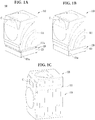
- FIGS. 1A to 1C are diagrams showing examples of implementations of a laundry treatment apparatus.
- the implementations of the laundry treatment apparatus may commonly include a first washing apparatus 110, which is a main laundry treatment apparatus, and a second washing apparatus 120, which is an auxiliary laundry treatment apparatus.
- the laundry treatment apparatus may not include both the first washing apparatus 110 and the second washing apparatus 120. That is, the laundry treatment apparatus may include either the first washing apparatus 110 or the second washing apparatus 120.
- the laundry treatment apparatus will be described as including a plurality of processing units merely for convenience of description, and the case in which the laundry treatment apparatus includes a single processing unit is not excluded.
- the second washing apparatus 120 may be configured as a washer for performing a washing cycle to remove foreign matter from laundry or as a dryer for performing a drying cycle to remove moisture from laundry. Even in the case in which the second washing apparatus 120 is configured as a washer, the second washing apparatus 120 may perform a drying cycle to dry laundry.
- the second washing apparatus 120 may be separably coupled to the first washing apparatus 110 (see FIG. 1A ) or may be integrated into the first washing apparatus 110 (see FIGS. 1B and 1C ).
- the second washing apparatus 120 may be configured as a drawer type laundry treatment apparatus in order to avoid interference with the front loading type laundry treatment apparatus.
- connection parts 111a may be configured as connectors for transmitting an electrical signal between the first washing apparatus 110 and the second washing apparatus 120.
- the second washing apparatus 120 may be configured to operate only when the first washing apparatus 110 is located on the second washing apparatus 120 in order to prevent the second washing apparatus 120 from overturning when the drawer 121a is withdrawn.
- the first washing apparatus 110 may be provided with a control panel C for displaying the status of the first washing apparatus 110 and the second washing apparatus 120 and allowing a user to input an operation command to the first washing apparatus 110 and the second washing apparatus 120.
- FIGS. 1B and 1C show implementations in which a first washing apparatus 110 and a second washing apparatus 120 are integrated into a single body.
- FIGS. 1B and 1C show the case in which the first washing apparatus 110 is configured as a top loading type laundry treatment apparatus and the second washing apparatus 120 is configured as a front loading type laundry treatment apparatus.
- FIG. 1B shows the case in which the second washing apparatus 120 is disposed under the first washing apparatus 110
- FIG. 1C shows the case in which the second washing apparatus 120 is disposed on the first washing apparatus 110.
- a first cabinet 111 that defines the external appearance of the first washing apparatus 110 and a second cabinet 121 that defines the external appearance of the second washing apparatus 120 may be coupled to each other in order to constitute a single body.
- the second washing apparatus 120 may include a drawer 121a configured to be withdrawn forward from the second cabinet 121 and a laundry receiving unit defined in the drawer 121a for receiving laundry.
- control panel C may be provided at the portion of the first cabinet 111 in which the second washing apparatus 120 is located.
- FIGS. 2 and 3 show the case in which the first washing apparatus 110 is configured as a front loading type laundry treatment apparatus and the second washing apparatus 120 is configured as a top loading type laundry treatment apparatus.
- the first washing apparatus 110 and the second washing apparatus 120 may be configured as other different types of laundry treatment apparatuses.
- the first washing apparatus 110 may include first laundry receiving units 112 and 113 provided in the first cabinet 111 for receiving laundry
- the second washing apparatus 120 may include a second laundry receiving unit 200 provided in the second cabinet 121 for receiving laundry.
- the first laundry receiving units 112 and 113 may include a first tub 112 for storing water and a first drum 113 rotatably provided in the first tub 112 for receiving laundry.
- the first washing apparatus 110 may further include a first driving unit 114 provided at one surface of the first tub 112 for rotating the first drum 113, a first water supply unit 115 for supplying water to the first tub 112, and a first drainage unit 116 for draining water from the first tub 112.
- the first drainage unit 116 may include a first drainage pipe 116a extending from the first tub 112 to the outside of the first cabinet 111 and a first drainage pump 116b for providing the power necessary to drain water from the first tub 112, the first drainage pump 116b communicating with the first drainage pipe 116a.
- the second washing apparatus 120 may have the same functions as the first washing apparatus 110 except that the second washing apparatus 120 is different in size from the first washing apparatus 110.
- the second washing apparatus 120 may include a second tub 122 provided on, under, or beside the first washing apparatus 110 for storing water, a second drum 200 rotatably provided in the second tub 122 for receiving laundry, a second driving unit 300 provided at one surface of the second tub 122 for rotating the second drum 200, a second water supply unit 125 for supplying water to the second tub 122, and a second drainage unit 126 for draining water from the second tub 122.
- a tub cover 120b is provided at the upper part of the second tub 122.
- the tub cover 120b covers the upper part of the second tub 122.
- the lateral space between the second tub 122 and the second drum 200 is covered by the tub cover 120b.
- the introduction port 122e in the second tub 122 is defined by the tub cover 120b. Consequently, the tub cover 120b may be mounted to the second tub 122.
- the second washing apparatus 120 may have a smaller volume than the first washing apparatus 110. However, it is necessary to provide a predetermined level of washing efficiency and washing capacity of the second washing apparatus 120.
- the second drum 200 may be configured such that the diameter of a drum introduction port, through which laundry is introduced, or the bottom surface 230 of the second drum is greater than the width of surfaces of the second drum adjacent to the drum introduction port.
- the second drum 200 may be configured such that the length of the surface perpendicular to a second shaft 330 is greater than that of the surface parallel to the shaft.
- the first support part 112a and the second support part 122a may be configured as a combination of a spring and a damper or as a combination of a bracket and a connection bar.
- the second water supply unit 125 may further include a divergence pipe 125c diverging from the second water supply pipe 125a and a spray nozzle 125d provided in the end of the divergence pipe 125c so as to face the interior of the second tub.
- a divergence valve 125e such as a three-way valve, may be provided in the connection part of the divergence pipe 125c and the second water supply pipe 125a.
- laundry received in the second drum 200 may be effectively wetted.
- the first hot air supply unit 119 may include a duct 119a for supplying air to the first tub 110, a duct heater 119b provided in the duct 119a, and a fan 119c for supplying air from the duct 119a to the first tub 112.
- the second washing apparatus 120 may include at least one selected from among a water level sensor 122b for sensing the level of water in the second tub 122, a temperature sensor 122d for sensing the temperature of the second tub 122, and a load sensor 122c for sensing the load of the second drum 200.
- the second washing apparatus 120 may further include an agitation unit 600 provided at the bottom surface of the second drum 200 for agitating laundry.
- the agitation unit 600 may agitate laundry as the laundry rotates around the agitation unit 600.
- the agitation unit 600 may improve the efficiency of washing of laundry if the second drum 200 is of relatively small size.
- the agitation unit 600 may be coupled to the bottom surface of the second drum 200 or may be integrally formed with the second drum 200. In some implementations, the agitation unit 600 may be rotatable together with the second drum 200.
- the agitation unit 600 may be rotatably provided at the bottom surface of the second drum 200 so as to be rotatable in the same direction as the second drum 200, to be rotatable in the direction opposite the direction in which the second drum 200 is rotated, or to be rotatable irrespective of the direction in which the second drum 200 is rotated.
- the drum introduction port may be configured as an open surface 211 formed at the upper part of the drum body.
- the drum introduction port may be configured as a through hole 223 provided in the balancer 220.
- the balancer 220 includes a housing 221 fixed to the open upper surface 211, a through hole (i.e. a housing through hole) 223 formed through the housing, and a channel 225 defined in the housing for allowing a fluid or a ball to circulate therealong, the through hole 223 may serve as the drum introduction port.
- the fluid or the ball may be provided in the channel 225.
- both the fluid and the ball may be provided in the channel 225.
- the drum body 210 is provided with a plurality of communication holes 215, through which the inside and the outside of the drum body communicate with each other. Consequently, the water stored in the second tub 122 may move into the drum body 210 through the communication holes 215, and the water in the drum body 210 may move to the second tub 122 through the communication holes 215.
- the second driving unit 300 may further include a shaft fixing unit 400 coupled to the drum bottom surface 230 for enabling easy coupling between the second shaft 330 and the drum bottom surface 230.
- the shaft fixing unit 400 may include a fixing body 410 located outside a space defined by the second drum 200 (i.e. a laundry receiving space) and a fixing arm 420 extending from the fixing body 410 toward the edge of the drum bottom surface 230.
- At least one selected from between the fixing body 410 and the fixing arm 420 may be fixed to the drum bottom surface 230.
- the second shaft 330 is fixed to the fixing body 410.
- the fixing arm 420 may include a first fixing arm 421, a second fixing arm 422, and a third fixing arm 423, which are arranged about the second shaft 330 so as to be spaced apart from each other by a predetermined angle.
- the first fixing arm 421, the second fixing arm 422, and the third fixing arm 423 may be spaced apart from each other by the same angle or by different angles.
- first fixing arm 421, the second fixing arm 422, and the third fixing arm 423 are spaced apart from each other by the same angle
- the first fixing arm 421, the second fixing arm 422, and the third fixing arm 423 may be spaced apart from each other by an angle of 120 degrees.
- the fixing arm 420 may be coupled to a base 231 provided at the drum bottom surface 230.
- the second washing apparatus 120 washes laundry using the rotational force of the second drum 200. Frictional mechanically force is generated in the second drum 200 by increasing and decreasing the rotational speed of the second drum 200 or changing the rotational direction of the second drum 200, whereby the laundry received in the second drum 200 is scrubbed.
- the second washing apparatus 120 may include an agitation unit 600 for applying mechanical force to the laundry received in the second drum 200 to improve washing efficiency.
- the drum bottom surface 230 may fix the agitation unit 600 through the base 231.
- a center part 61 provided at the center of the agitation unit 600 may protrude from the drum bottom surface 230 toward the drum introduction port 223, and the arms 63, 65, and 67 may include a first arm 63, a second arm 65, and a third arm 67 arranged about the center part 61 so as to be spaced apart from each other by an angle of 120 degrees.
- a larger number of arms or a smaller number of arms may be provided. In an implementation, the number of arms is three, to which, however, the present disclosure is not limited.
- the base 231 which is coupled to the agitation unit 600 or supports the agitation unit 600, may be provided at the drum bottom surface 230.
- the base 231 provided at the drum bottom surface 230 may support the arms 63, 65, and 67 or may be coupled to the arms 63, 65, and 67.
- the base 231 may include a first arm base 231a for supporting the first arm 63, a second arm base 231b for supporting the second arm 65, and a third arm base 231c for supporting the third arm 67.
- the agitation unit 600 may protrude into the second drum 200 such that the agitation unit 600 is rotated simultaneously when the second drum 200 is rotated to apply impact to the laundry, to push the laundry to the drum body 210, or to generate a strong stream of water in the water stored in the second tub 122, thereby maximizing the physical force applied to the laundry.
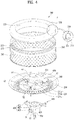
- FIGS. 5A and 5B show examples of the structure of the agitation unit 600.
- the agitation unit 600 may include an agitation unit body 620 fixed to the drum bottom surface 230 in a protruding fashion for agitating laundry and a reinforcement coupling part 640 received in the agitation unit body 620 for increasing the rigidity of the agitation unit body 620, the reinforcement coupling part 640 being coupled to the drum bottom surface 230 (hereinafter, referred to as the bottom surface) for fixing the agitation unit body 620 to the bottom surface 230.
- the reinforcement coupling part 640 may be a medium for coupling the agitation unit body 620 to the drum bottom surface 230.
- the reinforcement coupling part 640 may include a center part received in the agitation unit body 620 and fixed to the center of the bottom surface 230 and a plurality of arms 643, 645, and 647 radially extending from the center part.
- the reinforcement coupling part 640 may constitute the frame of the agitation unit 600, and the reinforcement coupling part 640 may serve as the surface of the agitation unit 600.
- the agitation unit body 620 may include a center part 621, in which the center part of the reinforcement coupling part 640 is received, and arms 623, 625, and 627, in which the arms 643, 645, and 647 of the reinforcement coupling part 640 are received.
- center part 621 and the arms 623, 625, and 627 of the agitation unit body 620 may be configured as a single housing.
- the agitation unit body 620 and the reinforcement coupling part 640 may be coupled to each other such that the center part 621 of the agitation unit body 620 and the center part of the reinforcement coupling part 640 constitute the center part 61 of the agitation unit 600 and such that the arms of the agitation unit body 620 and the arms of the reinforcement coupling part 640 constitute the first, second, and third arms 63, 65, and 67.
- the reinforcement coupling part 640 may be completely or partially received in the agitation unit body 620.
- the location holes 646 may be formed in the portions of the location plate 644 that correspond to the ends and the opposite side surfaces of the arms 643, 645, and 647 of the reinforcement coupling part 640 and that correspond to the portions of the center part of the reinforcement coupling part 640 between the arms.
- the second driving unit 300 may be provided under the agitation unit 600 to provide the power necessary to rotate at least one selected from between the agitation unit 600 and the second drum 200.
- the surface 650 of the agitation unit 600 may be plated.
- the reason for this is that, when the agitation unit 600 is made of a lighter material than the second drum 200 and the surface of the agitation unit 600 is then plated with a metal material, the moment of inertia is reduced and the agitation unit 600 is consistent with the interior of the second drum 200.
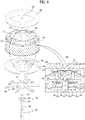
- the second washing apparatus 120 may include a coupling 500 provided between the agitation unit 600 and the second driving unit 300 so as to be rotated by the power from the second driving unit 300.
- the structure in which the power from the second driving unit 300 is transmitted to the coupling 500 will be described later.
- the coupling 500 may be provided in the second tub 122 so as to be disposed under the agitation unit 600.
- the coupling 500 may be configured to rotate the agitation unit 600 and the second drum 200 in different directions or to rotate only the agitation unit 600 when the level of water in the second tub 122 is a predetermined level or higher, and may be configured to rotate the agitation unit 600 and the second drum 200 in the same direction when the level of water in the second tub 122 is lower than the predetermined level.
- the coupling 500 may be made of a material having a lower specific gravity than water.
- the coupling 500 may be made of plastic.
- the coupling 500 may be made of engineered plastic or reinforced plastic.
- the coupling 500 may move upward toward the agitation unit 600.
- the coupling 500 may move away from the agitation unit 600.
- the level of water in the second tub 122 may be the predetermined level or higher.
- the level of water in the second tub 122 may be lower than the predetermined level. Consequently, the predetermined level may be defined as the level at which the agitation unit 600 is exposed to air.
- the coupling 500 may be configured to rotate the agitation unit 600 and the second drum 200 in different directions depending on the level of water in the second tub 122.
- the coupling 500 may be separated from the shaft fixing unit 400 and may then move upward toward the agitation unit 600.
- the coupling 500 may move downward and may then be coupled to the shaft fixing unit 400.
- the coupling 500 may directly receive power from the second driving unit 300.
- the coupling 500 may be coupled to the agitation unit 600 in order to rotate only the agitation unit 600, in implementations where the agitation unit 600 is separately rotatable.
- the coupling 500 may be coupled to the shaft fixing unit 400 in order to rotate the shaft fixing unit 400.
- the second driving unit 300 includes a shaft receiving unit 340 for rotatably receiving the second shaft 330.
- the second shaft 330 extends through the shaft receiving unit 340.
- the shaft fixing unit 400 may include a hub 410, to the lower part of which the shaft receiving unit 340 is coupled, the hub 410 including a shaft through part 411, through which the second shaft 330 extends, and fixing arms 420 radially extending from the hub 410 so as to be coupled to the bottom surface 230 of the drum.
- the second shaft 330 may be configured to be rotated by the second stator 310 and the second rotor 320 but not to directly rotate the shaft fixing unit 400 due to the shaft receiving unit 340.
- the second shaft 330 may be freely rotatable in the shaft receiving unit 340, and may extend through the shaft fixing unit 400.
- the agitation unit 600 may be coupled to the end of the second shaft 330 so as to be rotatable together with the second shaft 330. That is, the power generated from the second driving unit 300 may be directly transmitted to the agitation unit 600. However, the power generated from the second driving unit 300 is not directly transmitted to the shaft fixing unit 400.
- the coupling 500 may be provided above the hub 410 so as to be movable upward and downward along the second shaft 330 depending on a change in the level of water in the second tub 122.
- the second shaft 330 may include a shaft body 331 connected to the second rotor 320 and a shaft gear part 332 extending from the shaft body 331, the shaft gear 332 being provided on the outer circumferential surface of the portion thereof that protrudes from the hub 410 with a first gear 332a.
- the shaft through part 411 may include a hub gear 411a spaced apart from the shaft gear part 332 by a predetermined distance while receiving at least a portion of the shaft gear part 332.
- the hub gear 411a may be provided on the inner circumferential surface thereof with a second gear 411b.
- the first gear 332a may be provided on the portion of the second shaft 330 that is exposed upward from the hub 410.
- the power transmission part 510 may include a coupling gear 511, which is provided on the inner circumferential surface thereof with a third gear 511a configured to be engaged with the first gear 332a and to be movable in the longitudinal direction of the shaft gear part 332 and which is provided on the outer circumferential surface thereof with a fourth gear 511b configured to be engaged with the second gear 411b when the power transmission part 510 is inserted between the shaft gear part 332 and the hub gear 411a.
- a coupling gear 511 which is provided on the inner circumferential surface thereof with a third gear 511a configured to be engaged with the first gear 332a and to be movable in the longitudinal direction of the shaft gear part 332 and which is provided on the outer circumferential surface thereof with a fourth gear 511b configured to be engaged with the second gear 411b when the power transmission part 510 is inserted between the shaft gear part 332 and the hub gear 411a.
- the power transmission part 510 When water is introduced into the second tub 122, the power transmission part 510 may move upward in the longitudinal direction of the shaft gear part 332. When water is drained from the second tub 122, the power transmission part 510 may move downward in the longitudinal direction of the shaft gear part 332 and may then be inserted between the shaft gear part 332 and the hub gear 411a.
- the power transmission part 510 may directly receive power from the second shaft 330.
- the hub gear 411a is not rotated even when the shaft gear part 332 is rotated.
- the shaft fixing unit 400 and the second drum 200 are not rotated either.
- the agitation unit 600 may be rotated by the coupling 500.
- the agitation unit 600 may be continuously rotated together with the second shaft 330.
- the power transmission part 510 may be inserted between the shaft gear part 332 and the hub gear 411a.
- the fourth gear 511b of the coupling gear is engaged with the second gear 411b of the hub gear.
- the hub gear 411a may be rotated.
- the power transmission part 510 may transmit power generated from the second driving unit 300 to the shaft fixing unit 400 via the hub gear 411a, whereby the second drum 200 may be rotated.
- the agitation unit 600 may be rotated together with the shaft gear part 332, whereby the agitation unit 600 and the second drum 200 may be simultaneously rotated.
- the coupling 500 may further include a fixing plate 512 extending from the upper part of the coupling gear 511 such that the coupling gear is fixed to the fixing plate 512 and a receiving rib 513 extending from the end of the fixing plate 512 for separably receiving the hub gear 411a.
- a space for receiving the hub gear 411a may be provided under the receiving rib 513 and the fixing plate 512. Water may be introduced into the space. When water is supplied into the second tub 122, therefore, the coupling 500 may float.
- the coupling 500 may further include an extension rib 520 extending from the receiving rib 513 and an agitation coupling part 530 protruding from the end of the extension rib so as to be separably coupled to the lower part of the agitation unit 600.
- the agitation unit 600 may not be fixed to the second shaft 330 but may be freely rotated by the second shaft 330. In this case, the agitation unit 600 may contact the power transmission part 510, the agitation coupling part 530, and the extension rib 520 of the coupling 500. When the coupling 500 is rotated, therefore, the agitation unit 600 may also be rotated.
- the shaft receiving unit 340 may include a receiving pipe 341 for rotatably receiving a portion of the second shaft 330 and a receiving fixing part 342 extending from the upper part of the receiving pipe 341 so as to be coupled to the lower part of the hub 410. Consequently, the second shaft 330 may be rotated independently of the shaft receiving unit 340, whereby power may not be directly transmitted to the shaft fixing unit 400.
- the shaft through part 411 may further include a hub coupling part 411c provided separately from the hub 410 so as to be separably coupled to the hub 410 and extending from the outer circumferential surface of the hub gear 411a so as to be coupled to the hub 410.
- a hub coupling part 411c provided separately from the hub 410 so as to be separably coupled to the hub 410 and extending from the outer circumferential surface of the hub gear 411a so as to be coupled to the hub 410.
- the above structure may be advantageous when it is difficult to perform a single forming process from the hub 410 to the shaft through part 411 since the shape of the hub 410 is complicated.
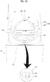
- FIGS. 7A and 7B show examples of the change in position of the coupling 500 depending on the level of water in the second tub 122.
- the coupling 500 may move upward until the upper part of the coupling 500 comes into contact with the lower part of the center part 61 of the agitation unit 600.
- the coupling 500 may rotate the agitation unit 600, since the coupling 500 is rotated by the shaft gear part 332. However, the coupling 500 does not rotate the shaft fixing unit 400, since the coupling 500 is separated from the hub gear 411a.
- the agitation unit 600 When the level of water in the second tub 122 is the predetermined level or higher, only the agitation unit 600 may be rotated. In the washing process, a stream of water is generated in the second drum 200, and laundry is appropriately twisted, thereby improving washing efficiency.
- the coupling 500 may rotate the agitation unit 600 while rotating.
- the agitation unit 600 may be rotated when the shaft gear part 332 is rotated.
- the shaft gear part 332, the coupling gear 511, and the hub gear 411a may be rotated at the same angular speed.
- the fixing unit 400 and the agitation unit 600 are simultaneously rotated, thereby achieving the effect of the fixing unit 400 and the agitation unit 600 being rotated as a single body.
- twisting of laundry is alleviated, thereby preventing damage to the laundry, since the second drum 200 and the agitation unit 600 are simultaneously rotated, rather than the agitation unit 600 rotating separately from the second drum 200.
- a controller 700 of the laundry treatment apparatus may control the first washing apparatus 110 and the second washing apparatus 120.
- the controller 700 may control all components of the first washing apparatus 110 and the second washing apparatus 120.
- the controller 700 may be connected to the control panel C so as to transmit and receive a control signal to and from the control panel C.
- the controller 700 may be integrated into the control panel C. Alternatively, the controller 700 may be provided separately from the control panel C.
- controller 700 may control the first water supply valve 115b, the second water supply valve 125b, the first driving unit 114, the second driving unit 300, the first drainage pump 116b, and the second drainage pump 126b.
- controller 700 may control the first heater 118 and the first hot air supply unit 119 of the first washing apparatus 110 and the second heater 128 and the second hot air supply unit 129 of the second washing apparatus 120.
- connection parts 111a may serve to transmit a control signal from the controller 700, which is provided in one selected from between the first washing apparatus 110 and the second washing apparatus 120.
- the laundry treatment apparatus may perform a course in which the first and second heaters 118 and 128 are driven. That is, the laundry treatment apparatus may perform a course in which the water stored in the first tub 112 or the second tub 122 is heated by the first and second heaters 118 and 128.
- the allergen-removing course may be a course in which the water in the first tub 112 or the second tub 122 is maintained at a temperature of 50 °C or higher for 10 minutes or more, and the boiling course may be a course in which the water in the first tub 112 or the second tub 122 is heated to a temperature of 50 °C or higher to remove foreign matter from laundry.
- the boiling course or the allergen-removing course in the case in which the boiling course or the allergen-removing course is performed in the second washing apparatus 120, it may not be preferable to heat water to the temperature required in the boiling course or the allergen-removing course after water is supplied into the second tub 122 to a predetermined level in order to perform the boiling course or the allergen-removing course.
- the first temperature may be about 90 °C, for example 86.4 °C.
- the second temperature may be about 50 °C.
- the second heater 128 when the water in the second tub 122 is heated, it is preferable for the second heater 128 to be immersed in the water. The reason for this is that, if the second heater 128 is operated in the state of being exposed to air, the second heater 128 may be overheated.
- the second heater 128 is provided between the bottom surface of the second tub 122 and the bottom surface of the second drum 2300, and the agitation unit 600 is provided above the second heater 128. In the case in which at least a portion of the agitation unit 600 is immersed in water, therefore, the second heater 128 is sufficiently immersed in the water.
- the laundry received in the second drum 200 is located above the agitation unit 600.
- the agitation unit 600 is immersed in water, therefore, the probability of the laundry being exposed to the water heated to the first temperature is very low.
- the controller 700 may perform control such that the second water supply valve 125b is opened until the water level sensor 122b senses the level of water in the second tub 122 at which at least a portion of the agitation unit 600 is immersed.
- the controller 700 may perform control such that the second water supply valve 125b is closed to interrupt the supply of water and the second heater 128 is operated to heat the water in the second tub 122 to the first temperature. Subsequently, when the temperature sensor 122d senses that the temperature of the water in the second tub 122 has reached the first temperature, the controller 700 may perform control such that the second water supply valve 125b is opened again to supply water to the second tub 122.
- the second heater 128 may be immersed, water may be supplied to a level at which the agitation unit 600 is exposed, and the second heater 128 may be operated to heat the water to the first temperature.
- the agitation unit 600 may also be heated to the first temperature due to heat balance.
- the portion of the second drum 200 that is located higher than the agitation unit 600 is not heated to the first temperature, with the result that a temperature difference relative to the agitation unit 600 may be created.
- the agitation unit 600 may thermally expand as the result of heating, but the portion of the second drum 200 may not thermally expand. As a result, the coupling between the agitation unit 600 and the portion of the second drum 200 may not be effectively achieved.
- the second drum 200 and the agitation unit 600 may rub against each other when the agitation unit 600 or the second drum 200 is rotated, whereby the agitation unit 600 or the second drum 200 may not be smoothly rotated.
- thermal impact may be applied to the agitation unit 600.
- the agitation unit 600 may be damaged, since the rate of thermal shrinkage of the agitation unit 600 is different from that of the second drum 200.
- the agitation unit 600 may be damaged due to the difference in thermal shrinkage.
- FIG. 9 shows a control method that is capable of preventing damage to the agitation unit 600.
- a level at which at least a portion of the agitation unit 600 is immersed in the water in the second tub 122 may be defined as a first level I
- a level at which the agitation unit 600 is entirely immersed in the water may be defined as a second level II
- a level at which the second heater 128 is immersed in the water may be defined as a third level III. That is, the level of water is increased in the order of the third level III, the first level I, and the second level II (see FIGS. 2 and 3 ).
- the controller 700 may determine the level of water in the second tub 122 by directly sensing the level of water in the second tub 122 through the water level sensor 122b or using data regarding the opening time of the second water supply valve 125b and the flow rate per unit time in the second water supply pipe 125a.
- the controller 700 may perform control so as to perform a water supply step (S1) of supplying water into the tub to a first level at which at least a portion of the agitation unit 600 is exposed, a heating step (S2) of operating the heater to heat the water in the tub to a first temperature, and a first additional water supply step (S3) of intermittently supplying water to a second level at which the entirety of the agitation unit 600 starts to be immersed in the water.
- a water supply step (S1) of supplying water into the tub to a first level at which at least a portion of the agitation unit 600 is exposed
- a first additional water supply step (S3) of intermittently supplying water to a second level at which the entirety of the agitation unit 600 starts to be immersed in the water.
- the first additional water supply step (S3) may be a step of slowly reducing the change in temperature in the tub.
- the first additional water supply step (S3) may be a step of stepwise reducing the change in temperature in the tub.
- the controller 700 may perform control such that the second water supply valve 125b is opened until water is supplied to the first level such that at least a portion of the agitation unit 600 is immersed in the water, the second heater 128 is operated to heat the water in the second tub 122, and the second water supply valve 125b is intermittently opened after the operation of the second heater 128 is completed.
- the controller 700 may perform control such that a small amount of water is supplied to the second tub 122, the second heater 128 is operated to heat the water to a high temperature, and the heated water is mixed with water supplied at the first additional water supply step, thereby obtaining a desired temperature.
- the agitation unit 600 may also be heated, and may be heated to the first temperature due to heat balance.
- water having a temperature lower than the first temperature is intermittently supplied to solve the above problem.
- the controller 700 may perform control such that water is supplied for a first predetermined amount of time at the first additional water supply step (S3), waiting is performed for a second predetermined amount of time, water is supplied again for the first predetermined amount of time, and waiting is performed for the second predetermined amount of time, which are repeated, thereby slowly reducing the temperature of the agitation unit 600.
- the agitation unit 600 may be prevented from being damaged even in the case in which the agitation unit 600 is made of a different material than the second drum 200 or includes a component made of a different material than the second drum 200.
- the difference in thermal shrinkage may be considerably reduced, thereby preventing the agitation unit 600 from being damaged.
- the difference in thermal shrinkage between the surface and the interior of the agitation unit 600 may be considerably reduced, thereby preventing the agitation unit 600 from being damaged.
- the temperature of the agitation unit 600 may be abruptly changed by even a small amount of water. For this reason, it is preferable for the first predetermined amount of time to be very short. In addition, it is necessary to secure a time for which the entirety of the agitation unit 600 reaches a thermal equilibrium state due to the water supplied for the first predetermined amount of time. For this reason, it is preferable for the second predetermined amount of time to be relatively long.
- the first predetermined amount of time may be 0.1 seconds, and the second predetermined amount of time may be 10 seconds. That is, when the operation of the second heater 128 is completed, the time for which the second water supply valve 125b is open may be shorter than the time for which the second water supply valve 125b is closed.
- water may be supplied into the second tub 122 in the form of spray, whereby a small amount of water may uniformly contact the large area of the agitation unit 600.
- the tub door 120a may be locked and unlocked by a push/open button type locking unit 432. That is, when the upper surface of the tub door 120a is pushed to close the tub door 120a, the tub door 120a is locked, and when the upper surface of the tub door 120a is pushed again to open the tub door 120a, the tub door 120a is unlocked.
- the reason that the upper surface of the tub is closed is that a large amount of bubbles may be generated in the tub 122 due to the rotation of the drum and the generated bubbles may flow outward through the upper surface of the tub, since the height of the tub 122 is smaller than the diameter of the tub 122. In order to solve this problem, the upper surface of the tub is closed.
- N1 times may be 30 times.
- the initial level sensing step (S200) is performed after the washing course selection step. At the initial level sensing step (S200), whether water is present in the tub 122 is determined before water is supplied into the tub 122.
- a drainage step (not show) of draining water to reduce the level of water in the tub 122 to a level for heating may be performed, followed by the heating step (S600), the washing water supply step (S800), and the main washing step (S900). Consequently, it is possible to make uniform the time for which the heating step is performed through the drainage step of draining water to reduce the level of water in the tub 122 to the level for heating, thereby saving energy.
- the washing water supply step (S800) and the main washing step (S900) are performed without performing the negative pressure prevention step (S700).
- the laundry treatment apparatus may include a water level sensor for transmitting electromagnetic waves (including ultrasonic waves) to water and receiving the electromagnetic waves reflected by the water.
- electromagnetic waves including ultrasonic waves
- the water level sensor is provided at the upper side of the tub 122 to measure the level of water stored in the tub 122.
- a water level frequency measured by the water level sensor is in inverse proportion to the level of water in the tub. That is, when the water level frequency is high, the level of water in the tub may be low, and when the water level frequency is low, the level of water in the tub may be high.
- the heater 128 installed at the bottom surface of the tub 122 is driven to heat the water stored in the tub 122.
- water is supplied to a first level, which is lower than a washing level for main washing. The reason for this is that a large amount of time is required to heat a large amount of water. Consequently, water is supplied into the tub 122 only to a first level at which laundry is sufficiently immersed in the water.
- tub door 120a or the tub cover 120b may be deformed, a gap may be formed between the tub door 120a and the tub cover 120b, or force may be applied to the tub door 120a such that the tub door is moved toward the inside of the tub, whereby the locking unit of the tub door 120a may be unlocked and thus the tub door 120a may open.f
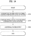
- FIG. 14 is a flowchart showing a control method for preventing negative pressure from being generated in the tub.
- the negative pressure prevention step (S700) will be described.
- the first predetermined amount of time may be shorter than the second predetermined amount of time.
- the second predetermined amount of time may be longer than the first predetermined amount of time.
- the first predetermined amount of time may be about 0.1 seconds
- the second predetermined amount of time may be about 2 seconds. Consequently, a small amount of water is supplied, and then waiting is performed for a relatively long time such that the heated water in the tub 122 sufficiently exchanges heat with the supplied water to achieve thermal equilibrium.
- the water supply time is shortened to supply a small amount of water into the tub such that the temperature of the heated water is not abruptly changed and such that negative pressure is not abruptly generated in the tub.
- the waiting time for which water is not supplied is long such that the water in the tub 122 sufficiently exchanges heat with the supplied water to achieve thermal equilibrium.
- the controller 700 performs control such that the water supply valve 125b is open for the first predetermined amount of time in order to supply water into the tub 122 through the spray nozzle and such that the water supply valve 125b is closed for the second predetermined amount of time to obtain the waiting time.
- the controller 700 performs control such that the water supply valve 125b is open for the first predetermined amount of time and is closed for the second predetermined amount of time, which is repeated twice.
- the negative pressure prevention step (S700) includes a comparative level sensing step (S720) of performing intermittent water supply N3 times and sensing a comparative level of water and a water level comparison step (S730) of comparing the sensed initial level of water with the sensed comparative level of water.
- the negative pressure prevention step (S700) may include an additional water supply step (S740) of further performing intermittent water supply N4 times based on the comparison result.
- the comparative level of water in the tub 122 is sensed within the second predetermined amount of time included in each time period for intermittent water supply.
- the comparative level of water in the tub 122 is sensed after the second predetermined amount of time included in each time period for intermittent water supply.
- the reason that the comparative level of water is measured after intermittent water supply at the comparative level sensing step (S720) is that negative pressure is generated in the tub due to the contraction of air caused by the abrupt change of temperature in the tub 122 only when the intermittent water supply is performed.
- N3 times may be 4 to 10 times, preferably 5 times.
- the reason that intermittent water supply is performed N3 times at the comparative level sensing step (S720) is that, when the comparative level of water is sensed after 1 to 3 times of intermittent water supply, the sensed comparative level of water may not reflect the level of water in the tub when a small amount of water is actually supplied into the tub. Consequently, the intermittent water supply is performed at least 5 times to set the comparative level of water to be used at the water level comparison step (S730).
- the highest one of the comparative levels of water sensed N3 times is selected as the comparative level of water sensed at the water level comparison step (S730) .
- the level of water in the tub is indirectly measured (i.e. in the case in which the water level frequency of the water level pipe communicating with the sealed tub is measured)
- the level of water in the tub at which the highest one of the water level frequencies sensed during N3 times of intermittent water supply is sensed is selected as the sensed comparative level of water. The reason for this is that, when the water level frequency is highest, the level of water in the tub is highest.
- the sensed comparative level of water is compared with the sensed initial level of water.
- N4 is not fixed but varies depending on the difference.
- N4 may be preset and stored in the form of a table.
- a laundry treatment apparatus may be configured such that an agitation unit is not damaged even when a course including heating to heat water is performed.
- a laundry treatment apparatus may be configured to mitigate an abrupt change in temperature of an agitation unit, thereby preventing damage to the agitation unit.
- the laundry treatment apparatus may be is configured to mitigate an abrupt change in temperature of an agitation unit in the case in which the agitation unit is made of materials having different coefficients of thermal expansion or includes parts having different coefficients of thermal expansion, thereby preventing damage to the agitation unit.
- a laundry treatment apparatus may be configured to perform slow stepwise cooling an agitation unit even when the agitation unit is heated to a high temperature.
- the laundry treatment apparatus is configured to mitigate abrupt negative pressure from being generated in a tub.
- the laundry treatment apparatus may be configured to mitigate abrupt negative pressure from being generated in a tub irrespective of the temperature of water supplied from the outside.
- a laundry treatment apparatus is configured to heat wash water and perform a washing cycle.
- a laundry treatment apparatus is configured to mitigate occurrences of a door being deformed or opened by negative pressure in a tub.
- the laundry treatment apparatus may be configured to mitigate instantaneously high negative pressure from being generated in a tub.
Landscapes
- Engineering & Computer Science (AREA)
- Textile Engineering (AREA)
- Water Supply & Treatment (AREA)
- Control Of Washing Machine And Dryer (AREA)
- Detail Structures Of Washing Machines And Dryers (AREA)
- Main Body Construction Of Washing Machines And Laundry Dryers (AREA)
Priority Applications (1)
| Application Number | Priority Date | Filing Date | Title |
|---|---|---|---|
| EP20192650.8A EP3779019B1 (fr) | 2017-02-27 | 2017-09-11 | Appareil de traitement du linge |
Applications Claiming Priority (1)
| Application Number | Priority Date | Filing Date | Title |
|---|---|---|---|
| KR1020170025737A KR102060067B1 (ko) | 2017-02-27 | 2017-02-27 | 의류처리장치 및 그 제어방법 |
Related Child Applications (1)
| Application Number | Title | Priority Date | Filing Date |
|---|---|---|---|
| EP20192650.8A Division EP3779019B1 (fr) | 2017-02-27 | 2017-09-11 | Appareil de traitement du linge |
Publications (2)
| Publication Number | Publication Date |
|---|---|
| EP3366824A1 true EP3366824A1 (fr) | 2018-08-29 |
| EP3366824B1 EP3366824B1 (fr) | 2020-08-26 |
Family
ID=59846457
Family Applications (2)
| Application Number | Title | Priority Date | Filing Date |
|---|---|---|---|
| EP20192650.8A Active EP3779019B1 (fr) | 2017-02-27 | 2017-09-11 | Appareil de traitement du linge |
| EP17190280.2A Active EP3366824B1 (fr) | 2017-02-27 | 2017-09-11 | Appareil de traitement de linge |
Family Applications Before (1)
| Application Number | Title | Priority Date | Filing Date |
|---|---|---|---|
| EP20192650.8A Active EP3779019B1 (fr) | 2017-02-27 | 2017-09-11 | Appareil de traitement du linge |
Country Status (6)
| Country | Link |
|---|---|
| US (2) | US10655267B2 (fr) |
| EP (2) | EP3779019B1 (fr) |
| KR (1) | KR102060067B1 (fr) |
| CN (1) | CN108505279B (fr) |
| AU (1) | AU2017204361B2 (fr) |
| CA (1) | CA2972483C (fr) |
Cited By (2)
| Publication number | Priority date | Publication date | Assignee | Title |
|---|---|---|---|---|
| CN111676649A (zh) * | 2019-02-25 | 2020-09-18 | 青岛海尔洗衣机有限公司 | 一种洗衣机控制方法及洗衣机 |
| US20230183901A1 (en) * | 2020-05-18 | 2023-06-15 | Lg Electronics Inc. | Laundry treating apparatus |
Families Citing this family (14)
| Publication number | Priority date | Publication date | Assignee | Title |
|---|---|---|---|---|
| WO2020228941A1 (fr) * | 2019-05-13 | 2020-11-19 | Electrolux Appliances Aktiebolag | Machine de traitement du linge et procédé de commande d'une telle machine de traitement du linge |
| US11028527B2 (en) * | 2019-09-27 | 2021-06-08 | Whirlpool Corporation | Laundry treating appliance for drying laundry |
| JP7285414B2 (ja) * | 2019-10-23 | 2023-06-02 | パナソニックIpマネジメント株式会社 | 洗濯機 |
| EP3889339B1 (fr) * | 2020-04-03 | 2023-08-09 | The Procter & Gamble Company | Procédé de lavage de linge |
| CN114351402A (zh) * | 2020-10-13 | 2022-04-15 | 青岛海尔洗衣机有限公司 | 一种洗衣机控制方法、装置、存储介质及洗衣机 |
| CN114575104A (zh) * | 2020-12-01 | 2022-06-03 | 青岛海尔洗衣机有限公司 | 洗衣设备及其自动设定进水水位的调整方法 |
| CN112856433A (zh) * | 2020-12-30 | 2021-05-28 | 林房均 | 一种固态废弃物焚烧装置 |
| CN112806939B (zh) * | 2021-01-22 | 2022-02-25 | 珠海格力电器股份有限公司 | 一种洗碗机及其控制方法、控制装置 |
| CN115707810B (zh) * | 2021-08-18 | 2025-11-25 | 青岛海尔洗涤电器有限公司 | 一种衣物处理设备 |
| KR20230100473A (ko) * | 2021-12-28 | 2023-07-05 | 삼성전자주식회사 | 세탁기의 급수 경로 제어 방법 및 그 방법을 수행하도록 구성되는 세탁기 |
| KR102635739B1 (ko) | 2022-04-12 | 2024-02-13 | 김진두 | 세탁 행정시간 단축 프로세스를 구비하는 세탁기 |
| CN116676755B (zh) * | 2022-02-23 | 2026-01-02 | 无锡小天鹅电器有限公司 | 一种混合装置及衣物处理设备 |
| CN116520714A (zh) * | 2023-01-30 | 2023-08-01 | 无锡小天鹅电器有限公司 | 运行控制方法、电器以及清洁处理设备 |
| CN115844296B (zh) * | 2023-03-03 | 2023-05-12 | 无锡小天鹅电器有限公司 | 一种清洁组合体的控制方法、装置、清洁组合体及介质 |
Citations (5)
| Publication number | Priority date | Publication date | Assignee | Title |
|---|---|---|---|---|
| EP0424780A2 (fr) * | 1989-10-24 | 1991-05-02 | Bosch-Siemens HausgerÀ¤te GmbH | Procédé d'introduction d'une phase programmée de rinçage dans une machine à laver |
| WO2012150539A2 (fr) * | 2011-05-02 | 2012-11-08 | Indesit Company S.P.A. | Appareil destiné à traiter des articles textiles et dispositif de lavage auxiliaire |
| WO2015082281A1 (fr) * | 2013-12-06 | 2015-06-11 | BSH Hausgeräte GmbH | Procédé permettant de traiter du linge avec une phase de mouillage améliorée et machine à laver adaptée au dit procédé |
| EP2949807A1 (fr) * | 2014-05-30 | 2015-12-02 | LG Electronics Inc. | Appareil de traitement du linge |
| KR20170025737A (ko) | 2015-08-31 | 2017-03-08 | 김병만 | 도미노 방식 풍력 발전기용 회전체 구조 |
Family Cites Families (12)
| Publication number | Priority date | Publication date | Assignee | Title |
|---|---|---|---|---|
| AU2003203729B2 (en) * | 2002-04-17 | 2005-10-13 | Lg Electronics Inc. | Pulsator and washing machine using the same |
| US8156590B2 (en) * | 2005-03-25 | 2012-04-17 | Lg Electronics Inc. | Controlling method of a laundry machine |
| ES2603220T3 (es) * | 2006-12-08 | 2017-02-24 | Lg Electronics Inc. | Máquina de lavar compleja y procedimiento de control de la misma |
| KR101414627B1 (ko) | 2007-12-03 | 2014-07-03 | 엘지전자 주식회사 | 의류 처리장치 |
| KR20120073586A (ko) * | 2010-12-27 | 2012-07-05 | 주식회사 대우일렉트로닉스 | 세탁기의 삶음세탁 제어방법 |
| RU2537276C2 (ru) | 2012-02-06 | 2014-12-27 | Эл Джи Электроникс Инк. | Машина для обработки белья |
| KR101634190B1 (ko) * | 2013-01-31 | 2016-06-28 | 엘지전자 주식회사 | 세탁기 및 이의 제어방법 |
| KR20140098485A (ko) | 2013-01-31 | 2014-08-08 | 엘지전자 주식회사 | 세탁기 및 이의 제어방법 |
| KR102207787B1 (ko) * | 2013-12-27 | 2021-01-26 | 삼성전자주식회사 | 세탁기 |
| US20160215432A1 (en) | 2015-01-27 | 2016-07-28 | Samsung Electronics Co., Ltd. | Washing machine and method for controlling the same |
| KR102351650B1 (ko) * | 2015-01-27 | 2022-01-17 | 삼성전자주식회사 | 세탁기 및 그 제어방법 |
| KR101683123B1 (ko) * | 2015-12-28 | 2016-12-06 | 엘지전자 주식회사 | 세탁기 및 이의 제어방법 |
-
2017
- 2017-02-27 KR KR1020170025737A patent/KR102060067B1/ko active Active
- 2017-06-27 AU AU2017204361A patent/AU2017204361B2/en active Active
- 2017-06-29 US US15/638,284 patent/US10655267B2/en active Active
- 2017-07-04 CA CA2972483A patent/CA2972483C/fr active Active
- 2017-09-11 EP EP20192650.8A patent/EP3779019B1/fr active Active
- 2017-09-11 EP EP17190280.2A patent/EP3366824B1/fr active Active
- 2017-10-03 US US15/723,347 patent/US10655268B2/en active Active
- 2017-11-10 CN CN201711102868.2A patent/CN108505279B/zh active Active
Patent Citations (5)
| Publication number | Priority date | Publication date | Assignee | Title |
|---|---|---|---|---|
| EP0424780A2 (fr) * | 1989-10-24 | 1991-05-02 | Bosch-Siemens HausgerÀ¤te GmbH | Procédé d'introduction d'une phase programmée de rinçage dans une machine à laver |
| WO2012150539A2 (fr) * | 2011-05-02 | 2012-11-08 | Indesit Company S.P.A. | Appareil destiné à traiter des articles textiles et dispositif de lavage auxiliaire |
| WO2015082281A1 (fr) * | 2013-12-06 | 2015-06-11 | BSH Hausgeräte GmbH | Procédé permettant de traiter du linge avec une phase de mouillage améliorée et machine à laver adaptée au dit procédé |
| EP2949807A1 (fr) * | 2014-05-30 | 2015-12-02 | LG Electronics Inc. | Appareil de traitement du linge |
| KR20170025737A (ko) | 2015-08-31 | 2017-03-08 | 김병만 | 도미노 방식 풍력 발전기용 회전체 구조 |
Cited By (3)
| Publication number | Priority date | Publication date | Assignee | Title |
|---|---|---|---|---|
| CN111676649A (zh) * | 2019-02-25 | 2020-09-18 | 青岛海尔洗衣机有限公司 | 一种洗衣机控制方法及洗衣机 |
| US20230183901A1 (en) * | 2020-05-18 | 2023-06-15 | Lg Electronics Inc. | Laundry treating apparatus |
| US12492498B2 (en) * | 2020-05-18 | 2025-12-09 | Lg Electronics Inc. | Laundry treating apparatus |
Also Published As
| Publication number | Publication date |
|---|---|
| US20180245268A1 (en) | 2018-08-30 |
| CA2972483A1 (fr) | 2018-08-27 |
| AU2017204361A1 (en) | 2018-09-13 |
| US10655267B2 (en) | 2020-05-19 |
| US10655268B2 (en) | 2020-05-19 |
| US20180245267A1 (en) | 2018-08-30 |
| CA2972483C (fr) | 2019-10-29 |
| CN108505279B (zh) | 2020-12-01 |
| KR102060067B1 (ko) | 2019-12-27 |
| AU2017204361B2 (en) | 2019-06-27 |
| EP3366824B1 (fr) | 2020-08-26 |
| EP3779019A1 (fr) | 2021-02-17 |
| EP3779019B1 (fr) | 2023-08-16 |
| KR20180104781A (ko) | 2018-09-27 |
| CN108505279A (zh) | 2018-09-07 |
Similar Documents
| Publication | Publication Date | Title |
|---|---|---|
| EP3779019B1 (fr) | Appareil de traitement du linge | |
| US11066770B2 (en) | Laundry treatment apparatus and method of controlling the same | |
| US9045852B2 (en) | Washing machine and washing control method of the same | |
| EP2118358B1 (fr) | Lave-linge complexe et son procédé de commande | |
| US10799021B2 (en) | Laundry treatment apparatus and method of controlling the same | |
| KR20220083370A (ko) | 의류 처리장치의 제어방법 | |
| EP3540112B1 (fr) | Compartiment à détergent et dispositif de traitement de vêtement le comprenant | |
| US20070169283A1 (en) | Washing machine and method for controlling the same | |
| KR102742995B1 (ko) | 인덕션 히터를 갖는 세탁장치 및 이의 제어방법 | |
| KR102017708B1 (ko) | 의류처리장치 및 그 제어방법 | |
| EP3730687A1 (fr) | Appareil de traitement de vêtements | |
| KR102545038B1 (ko) | 의류처리장치 및 그 제어방법 | |
| KR102318548B1 (ko) | 의류처리장치의 제어방법 | |
| US20170211220A1 (en) | Laundry treating appliance with tub and structural support |
Legal Events
| Date | Code | Title | Description |
|---|---|---|---|
| PUAI | Public reference made under article 153(3) epc to a published international application that has entered the european phase |
Free format text: ORIGINAL CODE: 0009012 |
|
| STAA | Information on the status of an ep patent application or granted ep patent |
Free format text: STATUS: REQUEST FOR EXAMINATION WAS MADE |
|
| 17P | Request for examination filed |
Effective date: 20170911 |
|
| AK | Designated contracting states |
Kind code of ref document: A1 Designated state(s): AL AT BE BG CH CY CZ DE DK EE ES FI FR GB GR HR HU IE IS IT LI LT LU LV MC MK MT NL NO PL PT RO RS SE SI SK SM TR |
|
| AX | Request for extension of the european patent |
Extension state: BA ME |
|
| RBV | Designated contracting states (corrected) |
Designated state(s): AL AT BE BG CH CY CZ DE DK EE ES FI FR GB GR HR HU IE IS IT LI LT LU LV MC MK MT NL NO PL PT RO RS SE SI SK SM TR |
|
| REG | Reference to a national code |
Ref country code: DE Ref legal event code: R079 Ref document number: 602017022253 Country of ref document: DE Free format text: PREVIOUS MAIN CLASS: D06F0033020000 Ipc: D06F0033320000 |
|
| RIC1 | Information provided on ipc code assigned before grant |
Ipc: D06F 33/32 20200101AFI20200130BHEP Ipc: D06F 105/02 20200101ALN20200130BHEP Ipc: D06F 31/00 20060101ALN20200130BHEP Ipc: D06F 103/16 20200101ALN20200130BHEP |
|
| GRAP | Despatch of communication of intention to grant a patent |
Free format text: ORIGINAL CODE: EPIDOSNIGR1 |
|
| STAA | Information on the status of an ep patent application or granted ep patent |
Free format text: STATUS: GRANT OF PATENT IS INTENDED |
|
| INTG | Intention to grant announced |
Effective date: 20200310 |
|
| RAP1 | Party data changed (applicant data changed or rights of an application transferred) |
Owner name: LG ELECTRONICS INC. |
|
| GRAS | Grant fee paid |
Free format text: ORIGINAL CODE: EPIDOSNIGR3 |
|
| GRAA | (expected) grant |
Free format text: ORIGINAL CODE: 0009210 |
|
| STAA | Information on the status of an ep patent application or granted ep patent |
Free format text: STATUS: THE PATENT HAS BEEN GRANTED |
|
| AK | Designated contracting states |
Kind code of ref document: B1 Designated state(s): AL AT BE BG CH CY CZ DE DK EE ES FI FR GB GR HR HU IE IS IT LI LT LU LV MC MK MT NL NO PL PT RO RS SE SI SK SM TR |
|
| REG | Reference to a national code |
Ref country code: GB Ref legal event code: FG4D |
|
| REG | Reference to a national code |
Ref country code: CH Ref legal event code: EP |
|
| REG | Reference to a national code |
Ref country code: AT Ref legal event code: REF Ref document number: 1306464 Country of ref document: AT Kind code of ref document: T Effective date: 20200915 |
|
| REG | Reference to a national code |
Ref country code: IE Ref legal event code: FG4D |
|
| REG | Reference to a national code |
Ref country code: DE Ref legal event code: R096 Ref document number: 602017022253 Country of ref document: DE |
|
| REG | Reference to a national code |
Ref country code: LT Ref legal event code: MG4D |
|
| PG25 | Lapsed in a contracting state [announced via postgrant information from national office to epo] |
Ref country code: NO Free format text: LAPSE BECAUSE OF FAILURE TO SUBMIT A TRANSLATION OF THE DESCRIPTION OR TO PAY THE FEE WITHIN THE PRESCRIBED TIME-LIMIT Effective date: 20201126 Ref country code: GR Free format text: LAPSE BECAUSE OF FAILURE TO SUBMIT A TRANSLATION OF THE DESCRIPTION OR TO PAY THE FEE WITHIN THE PRESCRIBED TIME-LIMIT Effective date: 20201127 Ref country code: PT Free format text: LAPSE BECAUSE OF FAILURE TO SUBMIT A TRANSLATION OF THE DESCRIPTION OR TO PAY THE FEE WITHIN THE PRESCRIBED TIME-LIMIT Effective date: 20201228 Ref country code: HR Free format text: LAPSE BECAUSE OF FAILURE TO SUBMIT A TRANSLATION OF THE DESCRIPTION OR TO PAY THE FEE WITHIN THE PRESCRIBED TIME-LIMIT Effective date: 20200826 Ref country code: LT Free format text: LAPSE BECAUSE OF FAILURE TO SUBMIT A TRANSLATION OF THE DESCRIPTION OR TO PAY THE FEE WITHIN THE PRESCRIBED TIME-LIMIT Effective date: 20200826 Ref country code: BG Free format text: LAPSE BECAUSE OF FAILURE TO SUBMIT A TRANSLATION OF THE DESCRIPTION OR TO PAY THE FEE WITHIN THE PRESCRIBED TIME-LIMIT Effective date: 20201126 Ref country code: SE Free format text: LAPSE BECAUSE OF FAILURE TO SUBMIT A TRANSLATION OF THE DESCRIPTION OR TO PAY THE FEE WITHIN THE PRESCRIBED TIME-LIMIT Effective date: 20200826 Ref country code: FI Free format text: LAPSE BECAUSE OF FAILURE TO SUBMIT A TRANSLATION OF THE DESCRIPTION OR TO PAY THE FEE WITHIN THE PRESCRIBED TIME-LIMIT Effective date: 20200826 |
|
| REG | Reference to a national code |
Ref country code: NL Ref legal event code: MP Effective date: 20200826 |
|
| REG | Reference to a national code |
Ref country code: AT Ref legal event code: MK05 Ref document number: 1306464 Country of ref document: AT Kind code of ref document: T Effective date: 20200826 |
|
| PG25 | Lapsed in a contracting state [announced via postgrant information from national office to epo] |
Ref country code: LV Free format text: LAPSE BECAUSE OF FAILURE TO SUBMIT A TRANSLATION OF THE DESCRIPTION OR TO PAY THE FEE WITHIN THE PRESCRIBED TIME-LIMIT Effective date: 20200826 Ref country code: RS Free format text: LAPSE BECAUSE OF FAILURE TO SUBMIT A TRANSLATION OF THE DESCRIPTION OR TO PAY THE FEE WITHIN THE PRESCRIBED TIME-LIMIT Effective date: 20200826 Ref country code: PL Free format text: LAPSE BECAUSE OF FAILURE TO SUBMIT A TRANSLATION OF THE DESCRIPTION OR TO PAY THE FEE WITHIN THE PRESCRIBED TIME-LIMIT Effective date: 20200826 Ref country code: NL Free format text: LAPSE BECAUSE OF FAILURE TO SUBMIT A TRANSLATION OF THE DESCRIPTION OR TO PAY THE FEE WITHIN THE PRESCRIBED TIME-LIMIT Effective date: 20200826 Ref country code: IS Free format text: LAPSE BECAUSE OF FAILURE TO SUBMIT A TRANSLATION OF THE DESCRIPTION OR TO PAY THE FEE WITHIN THE PRESCRIBED TIME-LIMIT Effective date: 20201226 |
|
| PG25 | Lapsed in a contracting state [announced via postgrant information from national office to epo] |
Ref country code: EE Free format text: LAPSE BECAUSE OF FAILURE TO SUBMIT A TRANSLATION OF THE DESCRIPTION OR TO PAY THE FEE WITHIN THE PRESCRIBED TIME-LIMIT Effective date: 20200826 Ref country code: SM Free format text: LAPSE BECAUSE OF FAILURE TO SUBMIT A TRANSLATION OF THE DESCRIPTION OR TO PAY THE FEE WITHIN THE PRESCRIBED TIME-LIMIT Effective date: 20200826 Ref country code: RO Free format text: LAPSE BECAUSE OF FAILURE TO SUBMIT A TRANSLATION OF THE DESCRIPTION OR TO PAY THE FEE WITHIN THE PRESCRIBED TIME-LIMIT Effective date: 20200826 Ref country code: DK Free format text: LAPSE BECAUSE OF FAILURE TO SUBMIT A TRANSLATION OF THE DESCRIPTION OR TO PAY THE FEE WITHIN THE PRESCRIBED TIME-LIMIT Effective date: 20200826 Ref country code: CZ Free format text: LAPSE BECAUSE OF FAILURE TO SUBMIT A TRANSLATION OF THE DESCRIPTION OR TO PAY THE FEE WITHIN THE PRESCRIBED TIME-LIMIT Effective date: 20200826 |
|
| REG | Reference to a national code |
Ref country code: CH Ref legal event code: PL |
|
| REG | Reference to a national code |
Ref country code: DE Ref legal event code: R097 Ref document number: 602017022253 Country of ref document: DE |
|
| PG25 | Lapsed in a contracting state [announced via postgrant information from national office to epo] |
Ref country code: ES Free format text: LAPSE BECAUSE OF FAILURE TO SUBMIT A TRANSLATION OF THE DESCRIPTION OR TO PAY THE FEE WITHIN THE PRESCRIBED TIME-LIMIT Effective date: 20200826 Ref country code: AL Free format text: LAPSE BECAUSE OF FAILURE TO SUBMIT A TRANSLATION OF THE DESCRIPTION OR TO PAY THE FEE WITHIN THE PRESCRIBED TIME-LIMIT Effective date: 20200826 Ref country code: AT Free format text: LAPSE BECAUSE OF FAILURE TO SUBMIT A TRANSLATION OF THE DESCRIPTION OR TO PAY THE FEE WITHIN THE PRESCRIBED TIME-LIMIT Effective date: 20200826 Ref country code: MC Free format text: LAPSE BECAUSE OF FAILURE TO SUBMIT A TRANSLATION OF THE DESCRIPTION OR TO PAY THE FEE WITHIN THE PRESCRIBED TIME-LIMIT Effective date: 20200826 |
|
| REG | Reference to a national code |
Ref country code: BE Ref legal event code: MM Effective date: 20200930 |
|
| PG25 | Lapsed in a contracting state [announced via postgrant information from national office to epo] |
Ref country code: LU Free format text: LAPSE BECAUSE OF NON-PAYMENT OF DUE FEES Effective date: 20200911 Ref country code: SK Free format text: LAPSE BECAUSE OF FAILURE TO SUBMIT A TRANSLATION OF THE DESCRIPTION OR TO PAY THE FEE WITHIN THE PRESCRIBED TIME-LIMIT Effective date: 20200826 |
|
| PLBE | No opposition filed within time limit |
Free format text: ORIGINAL CODE: 0009261 |
|
| STAA | Information on the status of an ep patent application or granted ep patent |
Free format text: STATUS: NO OPPOSITION FILED WITHIN TIME LIMIT |
|
| PG25 | Lapsed in a contracting state [announced via postgrant information from national office to epo] |
Ref country code: FR Free format text: LAPSE BECAUSE OF NON-PAYMENT OF DUE FEES Effective date: 20201026 |
|
| 26N | No opposition filed |
Effective date: 20210527 |
|
| PG25 | Lapsed in a contracting state [announced via postgrant information from national office to epo] |
Ref country code: SI Free format text: LAPSE BECAUSE OF FAILURE TO SUBMIT A TRANSLATION OF THE DESCRIPTION OR TO PAY THE FEE WITHIN THE PRESCRIBED TIME-LIMIT Effective date: 20200826 Ref country code: LI Free format text: LAPSE BECAUSE OF NON-PAYMENT OF DUE FEES Effective date: 20200930 Ref country code: IE Free format text: LAPSE BECAUSE OF NON-PAYMENT OF DUE FEES Effective date: 20200911 Ref country code: CH Free format text: LAPSE BECAUSE OF NON-PAYMENT OF DUE FEES Effective date: 20200930 Ref country code: BE Free format text: LAPSE BECAUSE OF NON-PAYMENT OF DUE FEES Effective date: 20200930 |
|
| GBPC | Gb: european patent ceased through non-payment of renewal fee |
Effective date: 20210911 |
|
| PG25 | Lapsed in a contracting state [announced via postgrant information from national office to epo] |
Ref country code: TR Free format text: LAPSE BECAUSE OF FAILURE TO SUBMIT A TRANSLATION OF THE DESCRIPTION OR TO PAY THE FEE WITHIN THE PRESCRIBED TIME-LIMIT Effective date: 20200826 Ref country code: MT Free format text: LAPSE BECAUSE OF FAILURE TO SUBMIT A TRANSLATION OF THE DESCRIPTION OR TO PAY THE FEE WITHIN THE PRESCRIBED TIME-LIMIT Effective date: 20200826 Ref country code: CY Free format text: LAPSE BECAUSE OF FAILURE TO SUBMIT A TRANSLATION OF THE DESCRIPTION OR TO PAY THE FEE WITHIN THE PRESCRIBED TIME-LIMIT Effective date: 20200826 |
|
| PG25 | Lapsed in a contracting state [announced via postgrant information from national office to epo] |
Ref country code: MK Free format text: LAPSE BECAUSE OF FAILURE TO SUBMIT A TRANSLATION OF THE DESCRIPTION OR TO PAY THE FEE WITHIN THE PRESCRIBED TIME-LIMIT Effective date: 20200826 |
|
| PG25 | Lapsed in a contracting state [announced via postgrant information from national office to epo] |
Ref country code: GB Free format text: LAPSE BECAUSE OF NON-PAYMENT OF DUE FEES Effective date: 20210911 |
|
| PGFP | Annual fee paid to national office [announced via postgrant information from national office to epo] |
Ref country code: DE Payment date: 20250805 Year of fee payment: 9 |
|
| PGFP | Annual fee paid to national office [announced via postgrant information from national office to epo] |
Ref country code: IT Payment date: 20250806 Year of fee payment: 9 |