EP3366824B1 - Wäschebehandlungsvorrichtung - Google Patents
Wäschebehandlungsvorrichtung Download PDFInfo
- Publication number
- EP3366824B1 EP3366824B1 EP17190280.2A EP17190280A EP3366824B1 EP 3366824 B1 EP3366824 B1 EP 3366824B1 EP 17190280 A EP17190280 A EP 17190280A EP 3366824 B1 EP3366824 B1 EP 3366824B1
- Authority
- EP
- European Patent Office
- Prior art keywords
- water
- tub
- water supply
- washing apparatus
- drum
- Prior art date
- Legal status (The legal status is an assumption and is not a legal conclusion. Google has not performed a legal analysis and makes no representation as to the accuracy of the status listed.)
- Active
Links
Images


Classifications
-
- D—TEXTILES; PAPER
- D06—TREATMENT OF TEXTILES OR THE LIKE; LAUNDERING; FLEXIBLE MATERIALS NOT OTHERWISE PROVIDED FOR
- D06F—LAUNDERING, DRYING, IRONING, PRESSING OR FOLDING TEXTILE ARTICLES
- D06F31/00—Washing installations comprising an assembly of several washing machines or washing units, e.g. continuous flow assemblies
-
- D—TEXTILES; PAPER
- D06—TREATMENT OF TEXTILES OR THE LIKE; LAUNDERING; FLEXIBLE MATERIALS NOT OTHERWISE PROVIDED FOR
- D06F—LAUNDERING, DRYING, IRONING, PRESSING OR FOLDING TEXTILE ARTICLES
- D06F39/00—Details of washing machines not specific to a single type of machines covered by groups D06F9/00 - D06F27/00
- D06F39/04—Heating arrangements
-
- A—HUMAN NECESSITIES
- A47—FURNITURE; DOMESTIC ARTICLES OR APPLIANCES; COFFEE MILLS; SPICE MILLS; SUCTION CLEANERS IN GENERAL
- A47L—DOMESTIC WASHING OR CLEANING; SUCTION CLEANERS IN GENERAL
- A47L15/00—Washing or rinsing machines for crockery or tableware
- A47L15/42—Details
- A47L15/4214—Water supply, recirculation or discharge arrangements; Devices therefor
-
- A—HUMAN NECESSITIES
- A47—FURNITURE; DOMESTIC ARTICLES OR APPLIANCES; COFFEE MILLS; SPICE MILLS; SUCTION CLEANERS IN GENERAL
- A47L—DOMESTIC WASHING OR CLEANING; SUCTION CLEANERS IN GENERAL
- A47L15/00—Washing or rinsing machines for crockery or tableware
- A47L15/42—Details
- A47L15/44—Devices for adding cleaning agents; Devices for dispensing cleaning agents, rinsing aids or deodorants
-
- D—TEXTILES; PAPER
- D06—TREATMENT OF TEXTILES OR THE LIKE; LAUNDERING; FLEXIBLE MATERIALS NOT OTHERWISE PROVIDED FOR
- D06F—LAUNDERING, DRYING, IRONING, PRESSING OR FOLDING TEXTILE ARTICLES
- D06F13/00—Washing machines having receptacles, stationary for washing purposes, with agitators therein contacting the articles being washed
-
- D—TEXTILES; PAPER
- D06—TREATMENT OF TEXTILES OR THE LIKE; LAUNDERING; FLEXIBLE MATERIALS NOT OTHERWISE PROVIDED FOR
- D06F—LAUNDERING, DRYING, IRONING, PRESSING OR FOLDING TEXTILE ARTICLES
- D06F33/00—Control of operations performed in washing machines or washer-dryers
- D06F33/30—Control of washing machines characterised by the purpose or target of the control
- D06F33/32—Control of operational steps, e.g. optimisation or improvement of operational steps depending on the condition of the laundry
- D06F33/34—Control of operational steps, e.g. optimisation or improvement of operational steps depending on the condition of the laundry of water filling
-
- D—TEXTILES; PAPER
- D06—TREATMENT OF TEXTILES OR THE LIKE; LAUNDERING; FLEXIBLE MATERIALS NOT OTHERWISE PROVIDED FOR
- D06F—LAUNDERING, DRYING, IRONING, PRESSING OR FOLDING TEXTILE ARTICLES
- D06F33/00—Control of operations performed in washing machines or washer-dryers
- D06F33/30—Control of washing machines characterised by the purpose or target of the control
- D06F33/44—Control of the operating time, e.g. reduction of overall operating time
-
- D—TEXTILES; PAPER
- D06—TREATMENT OF TEXTILES OR THE LIKE; LAUNDERING; FLEXIBLE MATERIALS NOT OTHERWISE PROVIDED FOR
- D06F—LAUNDERING, DRYING, IRONING, PRESSING OR FOLDING TEXTILE ARTICLES
- D06F34/00—Details of control systems for washing machines, washer-dryers or laundry dryers
- D06F34/14—Arrangements for detecting or measuring specific parameters
- D06F34/20—Parameters relating to constructional components, e.g. door sensors
-
- D—TEXTILES; PAPER
- D06—TREATMENT OF TEXTILES OR THE LIKE; LAUNDERING; FLEXIBLE MATERIALS NOT OTHERWISE PROVIDED FOR
- D06F—LAUNDERING, DRYING, IRONING, PRESSING OR FOLDING TEXTILE ARTICLES
- D06F34/00—Details of control systems for washing machines, washer-dryers or laundry dryers
- D06F34/14—Arrangements for detecting or measuring specific parameters
- D06F34/22—Condition of the washing liquid, e.g. turbidity
- D06F34/24—Liquid temperature
-
- D—TEXTILES; PAPER
- D06—TREATMENT OF TEXTILES OR THE LIKE; LAUNDERING; FLEXIBLE MATERIALS NOT OTHERWISE PROVIDED FOR
- D06F—LAUNDERING, DRYING, IRONING, PRESSING OR FOLDING TEXTILE ARTICLES
- D06F37/00—Details specific to washing machines covered by groups D06F21/00 - D06F25/00
- D06F37/02—Rotary receptacles, e.g. drums
- D06F37/12—Rotary receptacles, e.g. drums adapted for rotation or oscillation about a vertical axis
-
- D—TEXTILES; PAPER
- D06—TREATMENT OF TEXTILES OR THE LIKE; LAUNDERING; FLEXIBLE MATERIALS NOT OTHERWISE PROVIDED FOR
- D06F—LAUNDERING, DRYING, IRONING, PRESSING OR FOLDING TEXTILE ARTICLES
- D06F37/00—Details specific to washing machines covered by groups D06F21/00 - D06F25/00
- D06F37/30—Driving arrangements
- D06F37/40—Driving arrangements for driving the receptacle and an agitator or impeller, e.g. alternatively
-
- D—TEXTILES; PAPER
- D06—TREATMENT OF TEXTILES OR THE LIKE; LAUNDERING; FLEXIBLE MATERIALS NOT OTHERWISE PROVIDED FOR
- D06F—LAUNDERING, DRYING, IRONING, PRESSING OR FOLDING TEXTILE ARTICLES
- D06F37/00—Details specific to washing machines covered by groups D06F21/00 - D06F25/00
- D06F37/42—Safety arrangements, e.g. for stopping rotation of the receptacle upon opening of the casing door
-
- D—TEXTILES; PAPER
- D06—TREATMENT OF TEXTILES OR THE LIKE; LAUNDERING; FLEXIBLE MATERIALS NOT OTHERWISE PROVIDED FOR
- D06F—LAUNDERING, DRYING, IRONING, PRESSING OR FOLDING TEXTILE ARTICLES
- D06F39/00—Details of washing machines not specific to a single type of machines covered by groups D06F9/00 - D06F27/00
- D06F39/08—Liquid supply or discharge arrangements
- D06F39/083—Liquid discharge or recirculation arrangements
- D06F39/085—Arrangements or adaptations of pumps
-
- D—TEXTILES; PAPER
- D06—TREATMENT OF TEXTILES OR THE LIKE; LAUNDERING; FLEXIBLE MATERIALS NOT OTHERWISE PROVIDED FOR
- D06F—LAUNDERING, DRYING, IRONING, PRESSING OR FOLDING TEXTILE ARTICLES
- D06F39/00—Details of washing machines not specific to a single type of machines covered by groups D06F9/00 - D06F27/00
- D06F39/08—Liquid supply or discharge arrangements
- D06F39/088—Liquid supply arrangements
-
- A—HUMAN NECESSITIES
- A47—FURNITURE; DOMESTIC ARTICLES OR APPLIANCES; COFFEE MILLS; SPICE MILLS; SUCTION CLEANERS IN GENERAL
- A47L—DOMESTIC WASHING OR CLEANING; SUCTION CLEANERS IN GENERAL
- A47L15/00—Washing or rinsing machines for crockery or tableware
-
- D—TEXTILES; PAPER
- D06—TREATMENT OF TEXTILES OR THE LIKE; LAUNDERING; FLEXIBLE MATERIALS NOT OTHERWISE PROVIDED FOR
- D06F—LAUNDERING, DRYING, IRONING, PRESSING OR FOLDING TEXTILE ARTICLES
- D06F2103/00—Parameters monitored or detected for the control of domestic laundry washing machines, washer-dryers or laundry dryers
- D06F2103/16—Washing liquid temperature
-
- D—TEXTILES; PAPER
- D06—TREATMENT OF TEXTILES OR THE LIKE; LAUNDERING; FLEXIBLE MATERIALS NOT OTHERWISE PROVIDED FOR
- D06F—LAUNDERING, DRYING, IRONING, PRESSING OR FOLDING TEXTILE ARTICLES
- D06F2103/00—Parameters monitored or detected for the control of domestic laundry washing machines, washer-dryers or laundry dryers
- D06F2103/18—Washing liquid level
-
- D—TEXTILES; PAPER
- D06—TREATMENT OF TEXTILES OR THE LIKE; LAUNDERING; FLEXIBLE MATERIALS NOT OTHERWISE PROVIDED FOR
- D06F—LAUNDERING, DRYING, IRONING, PRESSING OR FOLDING TEXTILE ARTICLES
- D06F2105/00—Systems or parameters controlled or affected by the control systems of washing machines, washer-dryers or laundry dryers
- D06F2105/02—Water supply
-
- D—TEXTILES; PAPER
- D06—TREATMENT OF TEXTILES OR THE LIKE; LAUNDERING; FLEXIBLE MATERIALS NOT OTHERWISE PROVIDED FOR
- D06F—LAUNDERING, DRYING, IRONING, PRESSING OR FOLDING TEXTILE ARTICLES
- D06F2105/00—Systems or parameters controlled or affected by the control systems of washing machines, washer-dryers or laundry dryers
- D06F2105/06—Recirculation of washing liquids, e.g. by pumps or diverting valves
-
- D—TEXTILES; PAPER
- D06—TREATMENT OF TEXTILES OR THE LIKE; LAUNDERING; FLEXIBLE MATERIALS NOT OTHERWISE PROVIDED FOR
- D06F—LAUNDERING, DRYING, IRONING, PRESSING OR FOLDING TEXTILE ARTICLES
- D06F2105/00—Systems or parameters controlled or affected by the control systems of washing machines, washer-dryers or laundry dryers
- D06F2105/08—Draining of washing liquids
-
- D—TEXTILES; PAPER
- D06—TREATMENT OF TEXTILES OR THE LIKE; LAUNDERING; FLEXIBLE MATERIALS NOT OTHERWISE PROVIDED FOR
- D06F—LAUNDERING, DRYING, IRONING, PRESSING OR FOLDING TEXTILE ARTICLES
- D06F2105/00—Systems or parameters controlled or affected by the control systems of washing machines, washer-dryers or laundry dryers
- D06F2105/10—Temperature of washing liquids; Heating means therefor
-
- D—TEXTILES; PAPER
- D06—TREATMENT OF TEXTILES OR THE LIKE; LAUNDERING; FLEXIBLE MATERIALS NOT OTHERWISE PROVIDED FOR
- D06F—LAUNDERING, DRYING, IRONING, PRESSING OR FOLDING TEXTILE ARTICLES
- D06F2105/00—Systems or parameters controlled or affected by the control systems of washing machines, washer-dryers or laundry dryers
- D06F2105/46—Drum speed; Actuation of motors, e.g. starting or interrupting
-
- D—TEXTILES; PAPER
- D06—TREATMENT OF TEXTILES OR THE LIKE; LAUNDERING; FLEXIBLE MATERIALS NOT OTHERWISE PROVIDED FOR
- D06F—LAUNDERING, DRYING, IRONING, PRESSING OR FOLDING TEXTILE ARTICLES
- D06F23/00—Washing machines with receptacles, e.g. perforated, having a rotary movement, e.g. oscillatory movement, the receptacle serving both for washing and for centrifugally separating water from the laundry
- D06F23/04—Washing machines with receptacles, e.g. perforated, having a rotary movement, e.g. oscillatory movement, the receptacle serving both for washing and for centrifugally separating water from the laundry and rotating or oscillating about a vertical axis
-
- D—TEXTILES; PAPER
- D06—TREATMENT OF TEXTILES OR THE LIKE; LAUNDERING; FLEXIBLE MATERIALS NOT OTHERWISE PROVIDED FOR
- D06F—LAUNDERING, DRYING, IRONING, PRESSING OR FOLDING TEXTILE ARTICLES
- D06F39/00—Details of washing machines not specific to a single type of machines covered by groups D06F9/00 - D06F27/00
- D06F39/08—Liquid supply or discharge arrangements
- D06F39/087—Water level measuring or regulating devices
-
- D—TEXTILES; PAPER
- D06—TREATMENT OF TEXTILES OR THE LIKE; LAUNDERING; FLEXIBLE MATERIALS NOT OTHERWISE PROVIDED FOR
- D06F—LAUNDERING, DRYING, IRONING, PRESSING OR FOLDING TEXTILE ARTICLES
- D06F39/00—Details of washing machines not specific to a single type of machines covered by groups D06F9/00 - D06F27/00
- D06F39/12—Casings; Tubs
- D06F39/14—Doors or covers; Securing means therefor
Definitions
- Laundry treatment apparatuses are typically classified as a front loading type laundry treatment apparatus or a top loading type laundry treatment apparatus, depending on a direction in which laundry is loaded.
- An example of a front loading type laundry treatment apparatus is a drum washing machine or a drum drying machine.
- such difficulties may arise when water in a tub is heated using a heater in the small-sized laundry treatment apparatus.
- the water may be heated to a high temperature in the state in which a small amount of hot water is first supplied into the tub, followed by additionally supplying lower-temperature water to achieve the desired final temperature.
- the agitation unit when an initial amount of hot water is supplied in the small-sized laundry treatment apparatus, the agitation unit generally comes into contact with the water at the bottom of the tub. If the initially supplies water is heated, then the agitation unit is also heated. Subsequently, when lower-temperature water is supplied, the temperature of the heated agitation unit and the heated water is lowered to a desired final temperature.
- the controller may perform control so as to change the cycle at which or the time for which the water supply valve is opened and closed.
- a laundry treatment apparatus includes a cabinet defining the external appearance thereof, a tub provided in the cabinet for storing water, the tub being provided in the upper part thereof with an introduction port, through which laundry is introduced, a drum rotatably provided in the tub for receiving laundry, a door for opening and closing the introduction port, an agitation unit protruding upward from a center part of the bottom surface of the drum so as to agitate the water and the laundry as the laundry rotates around the agitator, a heater for heating the water in the tub, a water supply pipe connected to an external water supply source for supplying water to the tub, a water supply valve for opening and closing the water supply pipe, and a controller for controlling the operation of the water supply valve and the operation of the heater in the state in which the introduction port is closed by the door, wherein the controller controls the operation of the heater such that the water in the tub is heated to a boiling temperature at a boiling level and then controls the operation of the water supply valve such that the water supply valve supplies water through intermittent water supply
- the laundry treatment apparatus will be described as including a plurality of processing units merely for convenience of description, and the case in which the laundry treatment apparatus includes a single processing unit is not excluded.
- the reason for this is that it is necessary for the second washing apparatus 120 to rapidly wash or dry underwear, baby clothes, or a small amount of laundry while saving energy.
- the second washing apparatus 120 may be disposed on, under, or beside the first washing apparatus 110.
- the first washing apparatus 110 may be configured as a top loading type laundry treatment apparatus
- the second washing apparatus 120 may be configured as a front loading type laundry treatment apparatus.
- the second washing apparatus 120 may be disposed on, under, or beside the first washing apparatus 110.
- the first cabinet 111 may be provided with a control panel C for displaying the status of the first washing apparatus 110 and the second washing apparatus 120 and allowing a user to input an operation command to the first washing apparatus 110 and the second washing apparatus 120.
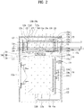
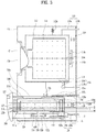
- FIGS. 2 and 3 show the interiors of laundry treatment apparatuses according to some implementations.
- a tub door 120a is provided to open and close the introduction port 122e of the second tub 122.
- the tub door 120a covers the introduction port 122e, the second tub 122 is substantially sealed.
- the introduction port 122e in the second tub 122 is defined by the tub cover 120b. Consequently, the tub cover 120b may be mounted to the second tub 122.
- the first support part 112a and the second support part 122a may be configured as a combination of a spring and a damper or as a combination of a bracket and a connection bar.
- the spray nozzle 125d may supply water to the second tub 122a in the form of spray.
- the second drainage unit 126 may include a second drainage pipe 126a extending from the second tub 122 to the outside of the first cabinet 121 and a second drainage pump 126b for providing power necessary to drain water from the second tub 122, the second drainage pump 126b communicating with the second drainage pipe 126a.
- the first washing apparatus 110 may include a first heater 118 for heating water in the first tub 112 and a first hot air supply unit 119 for supplying hot air to the first tub 110.
- the shape of the first heater 118 is not particularly restricted as long as the first heater 118 is capable of heating water in the first tub 110.
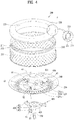
- the agitation unit 600 may be rotatably provided at the bottom surface of the second drum 200 so as to be rotatable in the same direction as the second drum 200, to be rotatable in the direction opposite the direction in which the second drum 200 is rotated, or to be rotatable irrespective of the direction in which the second drum 200 is rotated.
- the second driving unit 300 may further include a shaft fixing unit 400 coupled to the drum bottom surface 230 for enabling easy coupling between the second shaft 330 and the drum bottom surface 230.
- the agitation unit 600 may include a plurality of arms 63, 65, and 67 protruding from the drum bottom surface 230 and extending from the center of the drum bottom surface 230 toward the circumference of the drum body 210. That is, the arms 63, 65, and 67 may radially extend from the center of the drum bottom surface 230.
- the portion of the agitation unit 600 that contacts laundry and wash water and the portion of the agitation unit 600 that contacts the drum bottom surface 230 may be separately provided.
- the agitation unit body 620 and the reinforcement coupling part 640 may be coupled to each other such that the center part 621 of the agitation unit body 620 and the center part of the reinforcement coupling part 640 constitute the center part 61 of the agitation unit 600 and such that the arms of the agitation unit body 620 and the arms of the reinforcement coupling part 640 constitute the first, second, and third arms 63, 65, and 67.
- the coupling 500 may be made of plastic.
- the coupling 500 may be made of engineered plastic or reinforced plastic.
- the coupling 500 may move upward toward the agitation unit 600.
- the coupling 500 may move away from the agitation unit 600.
- the level of water in the second tub 122 may be the predetermined level or higher.
- the level of water in the second tub 122 may be lower than the predetermined level. Consequently, the predetermined level may be defined as the level at which the agitation unit 600 is exposed to air.
- the shaft fixing unit 400 may transmit power necessary to rotate the second drum 200.
- the power transmission part 510 may include a coupling gear 511, which is provided on the inner circumferential surface thereof with a third gear 511a configured to be engaged with the first gear 332a and to be movable in the longitudinal direction of the shaft gear part 332 and which is provided on the outer circumferential surface thereof with a fourth gear 511b configured to be engaged with the second gear 411b when the power transmission part 510 is inserted between the shaft gear part 332 and the hub gear 411a.
- a coupling gear 511 which is provided on the inner circumferential surface thereof with a third gear 511a configured to be engaged with the first gear 332a and to be movable in the longitudinal direction of the shaft gear part 332 and which is provided on the outer circumferential surface thereof with a fourth gear 511b configured to be engaged with the second gear 411b when the power transmission part 510 is inserted between the shaft gear part 332 and the hub gear 411a.
- a space which contacts water or into which water is introduced may be provided under the agitation coupling part 530 and the extension rib 520 such that the coupling 500 can more easily float.
- the agitation unit 600 may not be fixed to the second shaft 330 but may be freely rotated by the second shaft 330. In this case, the agitation unit 600 may contact the power transmission part 510, the agitation coupling part 530, and the extension rib 520 of the coupling 500. When the coupling 500 is rotated, therefore, the agitation unit 600 may also be rotated.
- the shaft through part 411 may further include a hub coupling part 411c provided separately from the hub 410 so as to be separably coupled to the hub 410 and extending from the outer circumferential surface of the hub gear 411a so as to be coupled to the hub 410.
- a hub coupling part 411c provided separately from the hub 410 so as to be separably coupled to the hub 410 and extending from the outer circumferential surface of the hub gear 411a so as to be coupled to the hub 410.
- the above structure may be advantageous when it is difficult to perform a single forming process from the hub 410 to the shaft through part 411 since the shape of the hub 410 is complicated.
- FIGS. 7A and 7B show examples of the change in position of the coupling 500 depending on the level of water in the second tub 122.
- the course may be an allergen-removing course for removing ticks and microorganisms from laundry or a boiling course for maximizing laundry washing force.
- the allergen-removing course may be a course in which the water in the first tub 112 or the second tub 122 is maintained at a temperature of 50 °C or higher for 10 minutes or more, and the boiling course may be a course in which the water in the first tub 112 or the second tub 122 is heated to a temperature of 50 °C or higher to remove foreign matter from laundry.
- the second heater 128 is provided between the bottom surface of the second tub 122 and the bottom surface of the second drum 2300, and the agitation unit 600 is provided above the second heater 128. In the case in which at least a portion of the agitation unit 600 is immersed in water, therefore, the second heater 128 is sufficiently immersed in the water.
- the laundry received in the second drum 200 is located above the agitation unit 600.
- the agitation unit 600 is immersed in water, therefore, the probability of the laundry being exposed to the water heated to the first temperature is very low.
- the controller 700 may perform control such that the second water supply valve 125b is opened until the water level sensor 122b senses the level of water in the second tub 122 at which at least a portion of the agitation unit 600 is immersed.
- the agitation unit 600 may be damaged due to the difference in thermal shrinkage.
- a level at which at least a portion of the agitation unit 600 is immersed in the water in the second tub 122 may be defined as a first level I
- a level at which the agitation unit 600 is entirely immersed in the water may be defined as a second level II
- a level at which the second heater 128 is immersed in the water may be defined as a third level III. That is, the level of water is increased in the order of the third level III, the first level I, and the second level II (see FIGS. 2 and 3 ).
- the controller 700 may determine the level of water in the second tub 122 by directly sensing the level of water in the second tub 122 through the water level sensor 122b or using data regarding the opening time of the second water supply valve 125b and the flow rate per unit time in the second water supply pipe 125a.
- the reason that the upper surface of the tub is closed is that a large amount of bubbles may be generated in the tub 122 due to the rotation of the drum and the generated bubbles may flow outward through the upper surface of the tub, since the height of the tub 122 is smaller than the diameter of the tub 122. In order to solve this problem, the upper surface of the tub is closed.
- FIG. 11 is a view showing the change in level of water in the tub when wash water is supplied to perform main washing.
- That the sensed initial level of water is higher than the predetermined level means that water has already been stored in the tub 122.
- the laundry treatment apparatus may include a water level sensor for transmitting electromagnetic waves (including ultrasonic waves) to water and receiving the electromagnetic waves reflected by the water.
- electromagnetic waves including ultrasonic waves
- the water level sensor may measure the level of water in a water level pipe that is vertically provided so as to be parallel to the tub 122.
- the water level pipe is connected to the lower side of the tub 122. Under atmospheric pressure, the level of water in the tub 122 is equal to the level of water in the water level pipe.
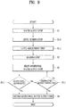
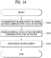
- FIG. 14 is a flowchart showing a control method for preventing negative pressure from being generated in the tub.
- the negative pressure prevention step (S700) will be described.
- intermittent water supply is performed to supply water into the tub 122 for a first predetermined amount of time and to interrupt the supply of water for a second predetermined amount of time.
- the first predetermined amount of time may be shorter than the second predetermined amount of time.
- the second predetermined amount of time may be longer than the first predetermined amount of time.
- the first predetermined amount of time may be about 0.1 seconds
- the second predetermined amount of time may be about 2 seconds. Consequently, a small amount of water is supplied, and then waiting is performed for a relatively long time such that the heated water in the tub 122 sufficiently exchanges heat with the supplied water to achieve thermal equilibrium.
- the water supply time is shortened to supply a small amount of water into the tub such that the temperature of the heated water is not abruptly changed and such that negative pressure is not abruptly generated in the tub.
- the waiting time for which water is not supplied is long such that the water in the tub 122 sufficiently exchanges heat with the supplied water to achieve thermal equilibrium.
- the negative pressure prevention step (S700) may include an additional water supply step (S740) of further performing intermittent water supply N4 times based on the comparison result.
- N3 times may be 4 to 10 times, preferably 5 times.
- the reason that intermittent water supply is performed N3 times at the comparative level sensing step (S720) is that, when the comparative level of water is sensed after 1 to 3 times of intermittent water supply, the sensed comparative level of water may not reflect the level of water in the tub when a small amount of water is actually supplied into the tub. Consequently, the intermittent water supply is performed at least 5 times to set the comparative level of water to be used at the water level comparison step (S730).
- the sensed comparative level of water is compared with the sensed initial level of water.
- N4 is not fixed but varies depending on the difference.
- N4 may be preset and stored in the form of a table.
- the negative pressure prevention step (S700) is performed again from the beginning. That is, in the case in which the laundry treatment apparatus is temporarily stopped or completely stopped during intermittent water supply, the comparative level sensing step (S720), the water level comparison step (S730), and the additional water supply step (S740) are sequentially performed.
- negative pressure may be instantaneously generated in the tub during the washing water supply.
- the generated negative pressure is not sufficiently high to deform the tub cover or the tub door or to unlock the push/open button type locking unit of the tub door. As a result, the tub door is not opened.
- a laundry treatment apparatus may be configured such that an agitation unit is not damaged even when a course including heating to heat water is performed.
- a laundry treatment apparatus may be configured to mitigate an abrupt change in temperature of an agitation unit, thereby preventing damage to the agitation unit.
- the laundry treatment apparatus may be is configured to mitigate an abrupt change in temperature of an agitation unit in the case in which the agitation unit is made of materials having different coefficients of thermal ex-pansion or includes parts having different coefficients of thermal expansion, thereby preventing damage to the agitation unit.
- a laundry treatment apparatus may be configured to perform slow stepwise cooling an agitation unit even when the agitation unit is heated to a high temperature.
- the laundry treatment apparatus is configured to mitigate abrupt negative pressure from being generated in a tub.
- the laundry treatment apparatus may be configured to mitigate abrupt negative pressure from being generated in a tub irrespective of the temperature of water supplied from the outside.
- a laundry treatment apparatus is configured to heat wash water and perform a washing cycle.
Landscapes
- Engineering & Computer Science (AREA)
- Textile Engineering (AREA)
- Water Supply & Treatment (AREA)
- Control Of Washing Machine And Dryer (AREA)
- Detail Structures Of Washing Machines And Dryers (AREA)
- Main Body Construction Of Washing Machines And Laundry Dryers (AREA)
Claims (15)
- Wäschebehandlungsvorrichtung, die Folgendes umfasst:eine erste Waschvorrichtung (110), die konfiguriert ist, Wäsche zu behandeln, die von einer Vorderseite der ersten Waschvorrichtung (110) durch eine erste Öffnung eingeführt wird; undeine zweite Waschvorrichtung (120), die konfiguriert ist, Wäsche zu behandeln, die von einer Oberseite der zweiten Waschvorrichtung (120) durch eine zweite Öffnung eingeführt wird,wobei die zweite Waschvorrichtung (120) Folgendes umfasst:einen Bottich (122), der konfiguriert ist, Wasser zu enthalten, und der eine Öffnung an einer Oberseite des Bottichs (122) aufweist, die durch die zweite Öffnung zugänglich ist;eine Bottichabdeckung (120b), die an dem Bottich (122) angeordnet ist und vorgesehen ist, um die Oberseite des Bottichs (122) zu bedecken, wobei die Bottichabdeckung (120b) eine Einführöffnung (122e) definiert, durch die der Innenraum des Bottichs (122) zugänglich ist;eine Bottichtür (120a), die an der Bottichabdeckung (120b) vorgesehen ist und konfiguriert ist, die Einführöffnung (122e) der Bottichabdeckung (120b) getrennt von der zweiten Öffnung zu öffnen und zu schließen, wobei der Bottich (122) in dem Fall, in dem die Bottichtür (120a) die Einführöffnung (122e) verschließt, im Wesentlichen abgedichtet ist;eine Trommel (200), die in dem Bottich (122) vorgesehen ist und konfiguriert ist, sich um eine vertikale Welle (330) zu drehen;eine Rühreinheit (600), die von einem zentralen Teil einer Bodenfläche der Trommel (200) nach oben vorsteht und konfiguriert ist, Wasser und Wäsche im Inneren der Trommel (200) in einem Zustand, in dem sich die Trommel (200) um die vertikale Welle (330) dreht, zu rühren;ein Heizelement (118), das konfiguriert ist, Wasser in dem Bottich (122) zu heizen;eine Wasserzufuhrleitung (125a), die konfiguriert ist, dem Bottich (122) Wasser zuzuführen;ein Wasserzufuhrventil (125b), das konfiguriert ist, eine Strömung durch die Wasserzufuhrleitung (125) zu steuern; dadurch gekennzeichnet, dass die Wäschebehandlungsvorrichtung ferner Folgendes umfasst:
wenigstens einen Prozessor, der konfiguriert ist, in einem Zustand, in dem die Einführöffnung (122e) durch die Bottichtür (120a) geschlossen ist, das Wasserzufuhrventil (125b) und das Heizelement (118) zu steuern, indem die folgenden Schritte ausgeführt werden:Steuern des Heizelements (118), um eine erste Wassermenge in dem Bottich (122) auf eine erste Temperatur zu heizen; undzeitweises Steuern des Wasserzufuhrventils (125b), um der ersten Wassermenge, die durch das Heizelement (118) auf die erste Temperatur geheizt wird oder geheizt worden ist, zusätzlich und zeitweise kleine Wassermengen dem Bottich (122) zuzuführen, um so einen Druckunterschied zwischen einem Innenraum und einem Außenraum des Bottichs (122) zu verringern. - Wäschebehandlungsvorrichtung nach Anspruch 1, wobei die zweite Waschvorrichtung (120) über der ersten Waschvorrichtung (110) angeordnet ist oder wobei die zweite Waschvorrichtung (120) unter der ersten Waschvorrichtung (110) angeordnet ist, wobei die Waschkapazität der zweiten Waschvorrichtung (120) kleiner als eine Waschkapazität der ersten Waschvorrichtung (110) ist.
- Wäschebehandlungsvorrichtung nach Anspruch 1 oder 2, wobei die zeitweise Steuerung des Wasserzufuhrventils (125b) zum Zuführen der kleinen Wassermengen in den Bottich (122) der zweiten Waschvorrichtung (120) die folgenden Schritte umfasst:Steuern des Wasserzufuhrventils (125b), um für eine Zufuhr von Wasser durch die Wasserzufuhrleitung (125a) in den Bottich (122) für eine erste Zeitspanne zu sorgen; undSteuern des Wasserzufuhrventils (125b), um die Zufuhr von Wasser durch die Wasserzufuhrleitung (125b) in den Bottich (122) für eine zweite Zeitspanne zu unterbrechen.
- Wäschebehandlungsvorrichtung nach Anspruch 3, wobei die zweite Zeitspanne länger als die erste Zeitspanne ist.
- Wäschebehandlungsvorrichtung nach Anspruch 3 oder 4, wobei die zeitweise Steuerung des Wasserzufuhrventils (125b) zum Zuführen der kleinen Wassermengen in den Bottich der zweiten Waschvorrichtung (120) den folgenden Schritt umfasst:
Steuern des Wasserzufuhrventils (125b), um mehrmals zwischen dem Bereitstellen der Zufuhr von Wasser durch die Wasserzufuhrleitung (125a) in den Bottich (122) für die erste Zeitspanne und dem Steuern des Wasserzufuhrventils (125b), um die Wasserzufuhr durch die Wasserzufuhrleitung (125a) in den Bottich (122) für die zweite Zeitspanne zu unterbrechen, abzuwechseln. - Wäschebehandlungsvorrichtung nach einem der vorhergehenden Ansprüche, wobei der wenigstens eine Prozessor ferner konfiguriert ist, die folgenden Schritte auszuführen:
nach dem Steuern des Wasserzufuhrventils (125b) zum Zuführen der kleinen Wassermengen in den Bottich der zweiten Waschvorrichtung (120):Steuern des Wasserzufuhrventils (125b), um dem Bottich (122) der zweiten Waschvorrichtung (120) zusätzlich eine zweite Wassermenge zuzuführen; undSteuern der zweiten Waschvorrichtung (120), um die Trommel (200) in dem Bottich (122) zu drehen, wobei dem Bottich (122) die zweite Wassermenge hinzugefügt worden ist. - Wäschebehandlungsvorrichtung nach Anspruch 6, wobei:die erste Wassermenge, die dem Bottich (122) hinzugefügt wird, eine erste Wasserhöhe in dem Bottich (122) zur Folge hat, bei der ein Abschnitt der Rühreinheit (600) unter die erste Wasserhöhe eintaucht und ein oberes Ende der Rühreinheit (600) über der ersten Wasserhöhe freiliegt, unddie zweite Wassermenge, die dem Bottich (122) hinzugefügt wird, eine zweite Wasserhöhe in dem Bottich (122) zur Folge hat, bei der das obere Ende der Rühreinheit (600) unter die zweite Wasserhöhe eintaucht.
- Wäschebehandlungsvorrichtung nach Anspruch 6 oder 7, wobei das Steuern des Heizelements (118) zum Heizen der ersten Wassermenge in dem Bottich (122) der zweiten Waschvorrichtung (120) auf die erste Temperatur das Heizen des Wassers in dem Bottich (122) auf eine höchste Temperatur von verfügbaren Wassertemperatur-Einstellwerten, die von der Wäschebehandlungsvorrichtung bereitgestellt werden, umfasst, und wobei die höchste Temperatur vorzugsweise etwa 90 °C oder mehr beträgt.
- Wäschebehandlungsvorrichtung nach einem der vorhergehenden Ansprüche, wobei die Rühreinheit (600) eine erste Oberfläche umfasst, die zu einem Innenraum der Trommel (200) der zweiten Waschvorrichtung (120) freiliegt, wobei die erste Oberfläche mit einem ersten Material beschichtet ist, wobei die Rühreinheit (600) vorzugsweise aus einem ersten Material besteht, das sich von einem zweiten Material der Trommel (200) unterscheidet.
- Wäschebehandlungsvorrichtung nach einem der vorhergehenden Ansprüche, die ferner Folgendes umfasst:einen Wasserhöhensensor (122b), der konfiguriert ist, eine Wasserhöhe in dem Bottich (122) der zweiten Waschvorrichtung (120) zu messen,wobei der wenigstens eine Prozessor ferner konfiguriert ist, die folgenden Schritte auszuführen:Steuern des Wasserzufuhrventils (125b), um dem Bottich (122) Wasser mit einer ersten Geschwindigkeit bis zu einem ersten Zeitpunkt zuzuführen, bei dem ein oberes Ende der Rühreinheit (600) unter eine Wasserhöhe des Bottichs (122) eintaucht; undnach dem ersten Zeitpunkt Steuern des Wasserzufuhrventils (125b), um dem Bottich (122) Wasser mit einer zweiten Geschwindigkeit zuzuführen, die niedriger als die erste Geschwindigkeit ist.
- Wäschebehandlungsvorrichtung nach einem der vorhergehenden Ansprüche, die ferner Folgendes umfasst:einen Temperatursensor (122d), der konfiguriert ist, eine Temperatur in dem Bottich (122) der zweiten Waschvorrichtung (120) zu messen,wobei der wenigstens eine Prozessor konfiguriert ist, die folgenden Schritte auszuführen:Steuern des Wasserzufuhrventils (125b), um dem Bottich (122) Wasser mit einer ersten Geschwindigkeit bis zu einem ersten Zeitpunkt zuzuführen, bei dem eine Temperatur, die durch den Temperatursensor (122d) gemessen wird, eine erste Bedingung erfüllt; undnach dem ersten Zeitpunkt Steuern des Wasserzufuhrventils (125b), um dem Bottich (122) Wasser mit einer zweiten Geschwindigkeit zuzuführen, die niedriger als die erste Geschwindigkeit ist.
- Wäschebehandlungsvorrichtung nach einem der vorhergehenden Ansprüche, wobei der wenigstens eine Prozessor ferner konfiguriert ist, das Wasserzufuhrventil (125b) und das Heizelement (118) durch den folgenden Schritt zu steuern:
während der Steuerung des Wasserzufuhrventils (125b), um dem Bottich (122) die kleinen Wassermengen zuzuführen, zeitweises Steuern des Heizelements (118), um die kleinen Wassermengen, die dem Bottich (122) hinzugefügt werden, zu heizen. - Wäschebehandlungsvorrichtung nach Anspruch 12, wobei der wenigstens eine Prozessor ferner konfiguriert ist, das Wasserzufuhrventil (125b) und das Heizelement (118) durch die folgenden Schritte zu steuern:Steuern des Wasserzufuhrventils (125b), um dem Bottich (122) eine erste kleine Wassermenge zuzuführen;Steuern des Heizelements (118), um das Wasser in dem Bottich (122) zu heizen;Detektieren, dass eine Temperatur des Wassers in dem Bottich (122) auf eine erste Temperatur geheizt ist; undauf der Basis der Detektion, dass die Temperatur des Wassers in dem Bottich (122) auf die erste Temperatur geheizt ist, Steuern des Wasserzufuhrventils (125b), um dem Bottich (122) eine zweite kleine Wassermenge zuzuführen.
- Wäschebehandlungsvorrichtung nach Anspruch 9, wobei die Rühreinheit (600) eine Oberfläche umfasst, die mit einem dritten Material beschichtet ist, das einen dritten Wärmeausdehnungskoeffizienten aufweist, der sich von einem ersten Wärmeausdehnungskoeffizienten des ersten Materials der Rühreinheit (600) unterscheidet.
- Wäschebehandlungsvorrichtung nach einem der vorhergehenden Ansprüche, wobei die Rühreinheit (600) konfiguriert ist, sich in Verbindung mit einer Drehung der Trommel (200) der zweiten Waschvorrichtung (120) zu drehen, oder wobei die Rühreinheit (600) konfiguriert ist, sich unabhängig von einer Drehung der Trommel (200) der zweiten Waschvorrichtung (120) zu drehen.
Priority Applications (1)
| Application Number | Priority Date | Filing Date | Title |
|---|---|---|---|
| EP20192650.8A EP3779019B1 (de) | 2017-02-27 | 2017-09-11 | Wäschebehandlungsvorrichtung |
Applications Claiming Priority (1)
| Application Number | Priority Date | Filing Date | Title |
|---|---|---|---|
| KR1020170025737A KR102060067B1 (ko) | 2017-02-27 | 2017-02-27 | 의류처리장치 및 그 제어방법 |
Related Child Applications (1)
| Application Number | Title | Priority Date | Filing Date |
|---|---|---|---|
| EP20192650.8A Division EP3779019B1 (de) | 2017-02-27 | 2017-09-11 | Wäschebehandlungsvorrichtung |
Publications (2)
| Publication Number | Publication Date |
|---|---|
| EP3366824A1 EP3366824A1 (de) | 2018-08-29 |
| EP3366824B1 true EP3366824B1 (de) | 2020-08-26 |
Family
ID=59846457
Family Applications (2)
| Application Number | Title | Priority Date | Filing Date |
|---|---|---|---|
| EP20192650.8A Active EP3779019B1 (de) | 2017-02-27 | 2017-09-11 | Wäschebehandlungsvorrichtung |
| EP17190280.2A Active EP3366824B1 (de) | 2017-02-27 | 2017-09-11 | Wäschebehandlungsvorrichtung |
Family Applications Before (1)
| Application Number | Title | Priority Date | Filing Date |
|---|---|---|---|
| EP20192650.8A Active EP3779019B1 (de) | 2017-02-27 | 2017-09-11 | Wäschebehandlungsvorrichtung |
Country Status (6)
| Country | Link |
|---|---|
| US (2) | US10655267B2 (de) |
| EP (2) | EP3779019B1 (de) |
| KR (1) | KR102060067B1 (de) |
| CN (1) | CN108505279B (de) |
| AU (1) | AU2017204361B2 (de) |
| CA (1) | CA2972483C (de) |
Families Citing this family (16)
| Publication number | Priority date | Publication date | Assignee | Title |
|---|---|---|---|---|
| CN111676649A (zh) * | 2019-02-25 | 2020-09-18 | 青岛海尔洗衣机有限公司 | 一种洗衣机控制方法及洗衣机 |
| AU2019445898B2 (en) * | 2019-05-13 | 2026-01-22 | Electrolux Appliances Aktiebolag | Laundry-treating machine and method for controlling such a laundry-treating machine |
| US11028527B2 (en) * | 2019-09-27 | 2021-06-08 | Whirlpool Corporation | Laundry treating appliance for drying laundry |
| JP7285414B2 (ja) * | 2019-10-23 | 2023-06-02 | パナソニックIpマネジメント株式会社 | 洗濯機 |
| EP3889339B1 (de) * | 2020-04-03 | 2023-08-09 | The Procter & Gamble Company | Verfahren zum waschen von stoff |
| EP4155448A4 (de) * | 2020-05-18 | 2024-05-29 | LG Electronics Inc. | Kleidungsverarbeitungsvorrichtung |
| CN114351402A (zh) * | 2020-10-13 | 2022-04-15 | 青岛海尔洗衣机有限公司 | 一种洗衣机控制方法、装置、存储介质及洗衣机 |
| CN114575104A (zh) * | 2020-12-01 | 2022-06-03 | 青岛海尔洗衣机有限公司 | 洗衣设备及其自动设定进水水位的调整方法 |
| CN112856433A (zh) * | 2020-12-30 | 2021-05-28 | 林房均 | 一种固态废弃物焚烧装置 |
| CN112806939B (zh) * | 2021-01-22 | 2022-02-25 | 珠海格力电器股份有限公司 | 一种洗碗机及其控制方法、控制装置 |
| CN115707810B (zh) * | 2021-08-18 | 2025-11-25 | 青岛海尔洗涤电器有限公司 | 一种衣物处理设备 |
| KR20230100473A (ko) * | 2021-12-28 | 2023-07-05 | 삼성전자주식회사 | 세탁기의 급수 경로 제어 방법 및 그 방법을 수행하도록 구성되는 세탁기 |
| KR102635739B1 (ko) | 2022-04-12 | 2024-02-13 | 김진두 | 세탁 행정시간 단축 프로세스를 구비하는 세탁기 |
| CN116676755B (zh) * | 2022-02-23 | 2026-01-02 | 无锡小天鹅电器有限公司 | 一种混合装置及衣物处理设备 |
| CN116520714A (zh) * | 2023-01-30 | 2023-08-01 | 无锡小天鹅电器有限公司 | 运行控制方法、电器以及清洁处理设备 |
| CN115844296B (zh) * | 2023-03-03 | 2023-05-12 | 无锡小天鹅电器有限公司 | 一种清洁组合体的控制方法、装置、清洁组合体及介质 |
Family Cites Families (17)
| Publication number | Priority date | Publication date | Assignee | Title |
|---|---|---|---|---|
| DE3935416A1 (de) | 1989-10-24 | 1991-04-25 | Bosch Siemens Hausgeraete | Verfahren zum einleiten eines spuelprogramm-abschnitts in einer automatisch gesteuerten trommel-waschmaschine |
| AU2003203729B2 (en) * | 2002-04-17 | 2005-10-13 | Lg Electronics Inc. | Pulsator and washing machine using the same |
| US8156590B2 (en) * | 2005-03-25 | 2012-04-17 | Lg Electronics Inc. | Controlling method of a laundry machine |
| EP3133202B1 (de) * | 2006-12-08 | 2019-07-17 | Lg Electronics Inc. | Zusatzwaschmaschine |
| KR101414627B1 (ko) | 2007-12-03 | 2014-07-03 | 엘지전자 주식회사 | 의류 처리장치 |
| KR20120073586A (ko) * | 2010-12-27 | 2012-07-05 | 주식회사 대우일렉트로닉스 | 세탁기의 삶음세탁 제어방법 |
| EP2949801B1 (de) | 2011-05-02 | 2017-10-25 | Whirlpool EMEA S.p.A | Vorrichtung zur behandlung von textilien und hilfswaschvorrichtung |
| EP2623664B1 (de) | 2012-02-06 | 2019-10-02 | LG Electronics Inc. | Steuerungsverfahren für eine Waschmaschine mit einem Trocknungskanal aufweisend eine Düse |
| KR20140098485A (ko) | 2013-01-31 | 2014-08-08 | 엘지전자 주식회사 | 세탁기 및 이의 제어방법 |
| KR101634190B1 (ko) * | 2013-01-31 | 2016-06-28 | 엘지전자 주식회사 | 세탁기 및 이의 제어방법 |
| DE102013225113B4 (de) | 2013-12-06 | 2019-01-31 | BSH Hausgeräte GmbH | Verfahren zur Behandlung von Wäsche mit verbesserter Benetzungsphase und hierzu geeignete Waschmaschine |
| KR102207787B1 (ko) * | 2013-12-27 | 2021-01-26 | 삼성전자주식회사 | 세탁기 |
| KR102487097B1 (ko) | 2014-05-30 | 2023-01-11 | 엘지전자 주식회사 | 의류처리장치 |
| KR102351650B1 (ko) * | 2015-01-27 | 2022-01-17 | 삼성전자주식회사 | 세탁기 및 그 제어방법 |
| US20160215432A1 (en) | 2015-01-27 | 2016-07-28 | Samsung Electronics Co., Ltd. | Washing machine and method for controlling the same |
| KR20170025737A (ko) | 2015-08-31 | 2017-03-08 | 김병만 | 도미노 방식 풍력 발전기용 회전체 구조 |
| KR101683123B1 (ko) * | 2015-12-28 | 2016-12-06 | 엘지전자 주식회사 | 세탁기 및 이의 제어방법 |
-
2017
- 2017-02-27 KR KR1020170025737A patent/KR102060067B1/ko active Active
- 2017-06-27 AU AU2017204361A patent/AU2017204361B2/en active Active
- 2017-06-29 US US15/638,284 patent/US10655267B2/en active Active
- 2017-07-04 CA CA2972483A patent/CA2972483C/en active Active
- 2017-09-11 EP EP20192650.8A patent/EP3779019B1/de active Active
- 2017-09-11 EP EP17190280.2A patent/EP3366824B1/de active Active
- 2017-10-03 US US15/723,347 patent/US10655268B2/en active Active
- 2017-11-10 CN CN201711102868.2A patent/CN108505279B/zh active Active
Non-Patent Citations (1)
| Title |
|---|
| None * |
Also Published As
| Publication number | Publication date |
|---|---|
| EP3779019A1 (de) | 2021-02-17 |
| CA2972483C (en) | 2019-10-29 |
| EP3366824A1 (de) | 2018-08-29 |
| KR102060067B1 (ko) | 2019-12-27 |
| KR20180104781A (ko) | 2018-09-27 |
| US10655267B2 (en) | 2020-05-19 |
| CN108505279A (zh) | 2018-09-07 |
| US20180245268A1 (en) | 2018-08-30 |
| US20180245267A1 (en) | 2018-08-30 |
| AU2017204361B2 (en) | 2019-06-27 |
| AU2017204361A1 (en) | 2018-09-13 |
| CA2972483A1 (en) | 2018-08-27 |
| CN108505279B (zh) | 2020-12-01 |
| EP3779019B1 (de) | 2023-08-16 |
| US10655268B2 (en) | 2020-05-19 |
Similar Documents
| Publication | Publication Date | Title |
|---|---|---|
| EP3366824B1 (de) | Wäschebehandlungsvorrichtung | |
| AU2020200011B2 (en) | Laundry treatment apparatus and method of controlling the same | |
| US9045852B2 (en) | Washing machine and washing control method of the same | |
| EP4012091B1 (de) | Wäschebehandlungsvorrichtung | |
| US10799021B2 (en) | Laundry treatment apparatus and method of controlling the same | |
| EP3540112B1 (de) | Reinigungsmittelbox und dazugehörige bekleidungsverarbeitungsvorrichtung | |
| US20070169283A1 (en) | Washing machine and method for controlling the same | |
| KR102742995B1 (ko) | 인덕션 히터를 갖는 세탁장치 및 이의 제어방법 | |
| KR102017708B1 (ko) | 의류처리장치 및 그 제어방법 | |
| EP3730687A1 (de) | Vorrichtung zur behandlung von kleidung | |
| KR102545038B1 (ko) | 의류처리장치 및 그 제어방법 | |
| KR102318548B1 (ko) | 의류처리장치의 제어방법 | |
| JPH03280991A (ja) | 回転ドラムを備える脱水装置 | |
| US20170211220A1 (en) | Laundry treating appliance with tub and structural support | |
| JP2018094112A (ja) | 洗濯乾燥機 |
Legal Events
| Date | Code | Title | Description |
|---|---|---|---|
| PUAI | Public reference made under article 153(3) epc to a published international application that has entered the european phase |
Free format text: ORIGINAL CODE: 0009012 |
|
| STAA | Information on the status of an ep patent application or granted ep patent |
Free format text: STATUS: REQUEST FOR EXAMINATION WAS MADE |
|
| 17P | Request for examination filed |
Effective date: 20170911 |
|
| AK | Designated contracting states |
Kind code of ref document: A1 Designated state(s): AL AT BE BG CH CY CZ DE DK EE ES FI FR GB GR HR HU IE IS IT LI LT LU LV MC MK MT NL NO PL PT RO RS SE SI SK SM TR |
|
| AX | Request for extension of the european patent |
Extension state: BA ME |
|
| RBV | Designated contracting states (corrected) |
Designated state(s): AL AT BE BG CH CY CZ DE DK EE ES FI FR GB GR HR HU IE IS IT LI LT LU LV MC MK MT NL NO PL PT RO RS SE SI SK SM TR |
|
| REG | Reference to a national code |
Ref country code: DE Ref legal event code: R079 Ref document number: 602017022253 Country of ref document: DE Free format text: PREVIOUS MAIN CLASS: D06F0033020000 Ipc: D06F0033320000 |
|
| RIC1 | Information provided on ipc code assigned before grant |
Ipc: D06F 33/32 20200101AFI20200130BHEP Ipc: D06F 105/02 20200101ALN20200130BHEP Ipc: D06F 31/00 20060101ALN20200130BHEP Ipc: D06F 103/16 20200101ALN20200130BHEP |
|
| GRAP | Despatch of communication of intention to grant a patent |
Free format text: ORIGINAL CODE: EPIDOSNIGR1 |
|
| STAA | Information on the status of an ep patent application or granted ep patent |
Free format text: STATUS: GRANT OF PATENT IS INTENDED |
|
| INTG | Intention to grant announced |
Effective date: 20200310 |
|
| RAP1 | Party data changed (applicant data changed or rights of an application transferred) |
Owner name: LG ELECTRONICS INC. |
|
| GRAS | Grant fee paid |
Free format text: ORIGINAL CODE: EPIDOSNIGR3 |
|
| GRAA | (expected) grant |
Free format text: ORIGINAL CODE: 0009210 |
|
| STAA | Information on the status of an ep patent application or granted ep patent |
Free format text: STATUS: THE PATENT HAS BEEN GRANTED |
|
| AK | Designated contracting states |
Kind code of ref document: B1 Designated state(s): AL AT BE BG CH CY CZ DE DK EE ES FI FR GB GR HR HU IE IS IT LI LT LU LV MC MK MT NL NO PL PT RO RS SE SI SK SM TR |
|
| REG | Reference to a national code |
Ref country code: GB Ref legal event code: FG4D |
|
| REG | Reference to a national code |
Ref country code: CH Ref legal event code: EP |
|
| REG | Reference to a national code |
Ref country code: AT Ref legal event code: REF Ref document number: 1306464 Country of ref document: AT Kind code of ref document: T Effective date: 20200915 |
|
| REG | Reference to a national code |
Ref country code: IE Ref legal event code: FG4D |
|
| REG | Reference to a national code |
Ref country code: DE Ref legal event code: R096 Ref document number: 602017022253 Country of ref document: DE |
|
| REG | Reference to a national code |
Ref country code: LT Ref legal event code: MG4D |
|
| PG25 | Lapsed in a contracting state [announced via postgrant information from national office to epo] |
Ref country code: NO Free format text: LAPSE BECAUSE OF FAILURE TO SUBMIT A TRANSLATION OF THE DESCRIPTION OR TO PAY THE FEE WITHIN THE PRESCRIBED TIME-LIMIT Effective date: 20201126 Ref country code: GR Free format text: LAPSE BECAUSE OF FAILURE TO SUBMIT A TRANSLATION OF THE DESCRIPTION OR TO PAY THE FEE WITHIN THE PRESCRIBED TIME-LIMIT Effective date: 20201127 Ref country code: PT Free format text: LAPSE BECAUSE OF FAILURE TO SUBMIT A TRANSLATION OF THE DESCRIPTION OR TO PAY THE FEE WITHIN THE PRESCRIBED TIME-LIMIT Effective date: 20201228 Ref country code: HR Free format text: LAPSE BECAUSE OF FAILURE TO SUBMIT A TRANSLATION OF THE DESCRIPTION OR TO PAY THE FEE WITHIN THE PRESCRIBED TIME-LIMIT Effective date: 20200826 Ref country code: LT Free format text: LAPSE BECAUSE OF FAILURE TO SUBMIT A TRANSLATION OF THE DESCRIPTION OR TO PAY THE FEE WITHIN THE PRESCRIBED TIME-LIMIT Effective date: 20200826 Ref country code: BG Free format text: LAPSE BECAUSE OF FAILURE TO SUBMIT A TRANSLATION OF THE DESCRIPTION OR TO PAY THE FEE WITHIN THE PRESCRIBED TIME-LIMIT Effective date: 20201126 Ref country code: SE Free format text: LAPSE BECAUSE OF FAILURE TO SUBMIT A TRANSLATION OF THE DESCRIPTION OR TO PAY THE FEE WITHIN THE PRESCRIBED TIME-LIMIT Effective date: 20200826 Ref country code: FI Free format text: LAPSE BECAUSE OF FAILURE TO SUBMIT A TRANSLATION OF THE DESCRIPTION OR TO PAY THE FEE WITHIN THE PRESCRIBED TIME-LIMIT Effective date: 20200826 |
|
| REG | Reference to a national code |
Ref country code: NL Ref legal event code: MP Effective date: 20200826 |
|
| REG | Reference to a national code |
Ref country code: AT Ref legal event code: MK05 Ref document number: 1306464 Country of ref document: AT Kind code of ref document: T Effective date: 20200826 |
|
| PG25 | Lapsed in a contracting state [announced via postgrant information from national office to epo] |
Ref country code: LV Free format text: LAPSE BECAUSE OF FAILURE TO SUBMIT A TRANSLATION OF THE DESCRIPTION OR TO PAY THE FEE WITHIN THE PRESCRIBED TIME-LIMIT Effective date: 20200826 Ref country code: RS Free format text: LAPSE BECAUSE OF FAILURE TO SUBMIT A TRANSLATION OF THE DESCRIPTION OR TO PAY THE FEE WITHIN THE PRESCRIBED TIME-LIMIT Effective date: 20200826 Ref country code: PL Free format text: LAPSE BECAUSE OF FAILURE TO SUBMIT A TRANSLATION OF THE DESCRIPTION OR TO PAY THE FEE WITHIN THE PRESCRIBED TIME-LIMIT Effective date: 20200826 Ref country code: NL Free format text: LAPSE BECAUSE OF FAILURE TO SUBMIT A TRANSLATION OF THE DESCRIPTION OR TO PAY THE FEE WITHIN THE PRESCRIBED TIME-LIMIT Effective date: 20200826 Ref country code: IS Free format text: LAPSE BECAUSE OF FAILURE TO SUBMIT A TRANSLATION OF THE DESCRIPTION OR TO PAY THE FEE WITHIN THE PRESCRIBED TIME-LIMIT Effective date: 20201226 |
|
| PG25 | Lapsed in a contracting state [announced via postgrant information from national office to epo] |
Ref country code: EE Free format text: LAPSE BECAUSE OF FAILURE TO SUBMIT A TRANSLATION OF THE DESCRIPTION OR TO PAY THE FEE WITHIN THE PRESCRIBED TIME-LIMIT Effective date: 20200826 Ref country code: SM Free format text: LAPSE BECAUSE OF FAILURE TO SUBMIT A TRANSLATION OF THE DESCRIPTION OR TO PAY THE FEE WITHIN THE PRESCRIBED TIME-LIMIT Effective date: 20200826 Ref country code: RO Free format text: LAPSE BECAUSE OF FAILURE TO SUBMIT A TRANSLATION OF THE DESCRIPTION OR TO PAY THE FEE WITHIN THE PRESCRIBED TIME-LIMIT Effective date: 20200826 Ref country code: DK Free format text: LAPSE BECAUSE OF FAILURE TO SUBMIT A TRANSLATION OF THE DESCRIPTION OR TO PAY THE FEE WITHIN THE PRESCRIBED TIME-LIMIT Effective date: 20200826 Ref country code: CZ Free format text: LAPSE BECAUSE OF FAILURE TO SUBMIT A TRANSLATION OF THE DESCRIPTION OR TO PAY THE FEE WITHIN THE PRESCRIBED TIME-LIMIT Effective date: 20200826 |
|
| REG | Reference to a national code |
Ref country code: CH Ref legal event code: PL |
|
| REG | Reference to a national code |
Ref country code: DE Ref legal event code: R097 Ref document number: 602017022253 Country of ref document: DE |
|
| PG25 | Lapsed in a contracting state [announced via postgrant information from national office to epo] |
Ref country code: ES Free format text: LAPSE BECAUSE OF FAILURE TO SUBMIT A TRANSLATION OF THE DESCRIPTION OR TO PAY THE FEE WITHIN THE PRESCRIBED TIME-LIMIT Effective date: 20200826 Ref country code: AL Free format text: LAPSE BECAUSE OF FAILURE TO SUBMIT A TRANSLATION OF THE DESCRIPTION OR TO PAY THE FEE WITHIN THE PRESCRIBED TIME-LIMIT Effective date: 20200826 Ref country code: AT Free format text: LAPSE BECAUSE OF FAILURE TO SUBMIT A TRANSLATION OF THE DESCRIPTION OR TO PAY THE FEE WITHIN THE PRESCRIBED TIME-LIMIT Effective date: 20200826 Ref country code: MC Free format text: LAPSE BECAUSE OF FAILURE TO SUBMIT A TRANSLATION OF THE DESCRIPTION OR TO PAY THE FEE WITHIN THE PRESCRIBED TIME-LIMIT Effective date: 20200826 |
|
| REG | Reference to a national code |
Ref country code: BE Ref legal event code: MM Effective date: 20200930 |
|
| PG25 | Lapsed in a contracting state [announced via postgrant information from national office to epo] |
Ref country code: LU Free format text: LAPSE BECAUSE OF NON-PAYMENT OF DUE FEES Effective date: 20200911 Ref country code: SK Free format text: LAPSE BECAUSE OF FAILURE TO SUBMIT A TRANSLATION OF THE DESCRIPTION OR TO PAY THE FEE WITHIN THE PRESCRIBED TIME-LIMIT Effective date: 20200826 |
|
| PLBE | No opposition filed within time limit |
Free format text: ORIGINAL CODE: 0009261 |
|
| STAA | Information on the status of an ep patent application or granted ep patent |
Free format text: STATUS: NO OPPOSITION FILED WITHIN TIME LIMIT |
|
| PG25 | Lapsed in a contracting state [announced via postgrant information from national office to epo] |
Ref country code: FR Free format text: LAPSE BECAUSE OF NON-PAYMENT OF DUE FEES Effective date: 20201026 |
|
| 26N | No opposition filed |
Effective date: 20210527 |
|
| PG25 | Lapsed in a contracting state [announced via postgrant information from national office to epo] |
Ref country code: SI Free format text: LAPSE BECAUSE OF FAILURE TO SUBMIT A TRANSLATION OF THE DESCRIPTION OR TO PAY THE FEE WITHIN THE PRESCRIBED TIME-LIMIT Effective date: 20200826 Ref country code: LI Free format text: LAPSE BECAUSE OF NON-PAYMENT OF DUE FEES Effective date: 20200930 Ref country code: IE Free format text: LAPSE BECAUSE OF NON-PAYMENT OF DUE FEES Effective date: 20200911 Ref country code: CH Free format text: LAPSE BECAUSE OF NON-PAYMENT OF DUE FEES Effective date: 20200930 Ref country code: BE Free format text: LAPSE BECAUSE OF NON-PAYMENT OF DUE FEES Effective date: 20200930 |
|
| GBPC | Gb: european patent ceased through non-payment of renewal fee |
Effective date: 20210911 |
|
| PG25 | Lapsed in a contracting state [announced via postgrant information from national office to epo] |
Ref country code: TR Free format text: LAPSE BECAUSE OF FAILURE TO SUBMIT A TRANSLATION OF THE DESCRIPTION OR TO PAY THE FEE WITHIN THE PRESCRIBED TIME-LIMIT Effective date: 20200826 Ref country code: MT Free format text: LAPSE BECAUSE OF FAILURE TO SUBMIT A TRANSLATION OF THE DESCRIPTION OR TO PAY THE FEE WITHIN THE PRESCRIBED TIME-LIMIT Effective date: 20200826 Ref country code: CY Free format text: LAPSE BECAUSE OF FAILURE TO SUBMIT A TRANSLATION OF THE DESCRIPTION OR TO PAY THE FEE WITHIN THE PRESCRIBED TIME-LIMIT Effective date: 20200826 |
|
| PG25 | Lapsed in a contracting state [announced via postgrant information from national office to epo] |
Ref country code: MK Free format text: LAPSE BECAUSE OF FAILURE TO SUBMIT A TRANSLATION OF THE DESCRIPTION OR TO PAY THE FEE WITHIN THE PRESCRIBED TIME-LIMIT Effective date: 20200826 |
|
| PG25 | Lapsed in a contracting state [announced via postgrant information from national office to epo] |
Ref country code: GB Free format text: LAPSE BECAUSE OF NON-PAYMENT OF DUE FEES Effective date: 20210911 |
|
| PGFP | Annual fee paid to national office [announced via postgrant information from national office to epo] |
Ref country code: DE Payment date: 20250805 Year of fee payment: 9 |
|
| PGFP | Annual fee paid to national office [announced via postgrant information from national office to epo] |
Ref country code: IT Payment date: 20250806 Year of fee payment: 9 |