EP3366867A1 - Aufblasbares schwimmbecken und verfahren zur herstellung davon - Google Patents
Aufblasbares schwimmbecken und verfahren zur herstellung davon Download PDFInfo
- Publication number
- EP3366867A1 EP3366867A1 EP17174811.4A EP17174811A EP3366867A1 EP 3366867 A1 EP3366867 A1 EP 3366867A1 EP 17174811 A EP17174811 A EP 17174811A EP 3366867 A1 EP3366867 A1 EP 3366867A1
- Authority
- EP
- European Patent Office
- Prior art keywords
- piece
- annular
- annular body
- welding
- pool
- Prior art date
- Legal status (The legal status is an assumption and is not a legal conclusion. Google has not performed a legal analysis and makes no representation as to the accuracy of the status listed.)
- Withdrawn
Links
- 238000000034 method Methods 0.000 title claims abstract description 18
- 238000003466 welding Methods 0.000 claims description 83
- 230000000694 effects Effects 0.000 description 7
- 238000004023 plastic welding Methods 0.000 description 5
- XLYOFNOQVPJJNP-UHFFFAOYSA-N water Substances O XLYOFNOQVPJJNP-UHFFFAOYSA-N 0.000 description 5
- -1 Polyethylene Polymers 0.000 description 3
- 239000004698 Polyethylene Substances 0.000 description 2
- 239000004743 Polypropylene Substances 0.000 description 2
- 238000004026 adhesive bonding Methods 0.000 description 2
- 230000004048 modification Effects 0.000 description 2
- 238000012986 modification Methods 0.000 description 2
- 229920000139 polyethylene terephthalate Polymers 0.000 description 2
- 239000005020 polyethylene terephthalate Substances 0.000 description 2
- 241001465754 Metazoa Species 0.000 description 1
- 239000004677 Nylon Substances 0.000 description 1
- 230000004927 fusion Effects 0.000 description 1
- 230000010354 integration Effects 0.000 description 1
- 230000003993 interaction Effects 0.000 description 1
- 229920001778 nylon Polymers 0.000 description 1
- 239000004033 plastic Substances 0.000 description 1
- 229920003023 plastic Polymers 0.000 description 1
- 229920000573 polyethylene Polymers 0.000 description 1
- 229920001155 polypropylene Polymers 0.000 description 1
- 238000003825 pressing Methods 0.000 description 1
- 230000008569 process Effects 0.000 description 1
- 239000007787 solid Substances 0.000 description 1
- 238000005507 spraying Methods 0.000 description 1
- 230000007704 transition Effects 0.000 description 1
Images



Classifications
-
- E—FIXED CONSTRUCTIONS
- E04—BUILDING
- E04H—BUILDINGS OR LIKE STRUCTURES FOR PARTICULAR PURPOSES; SWIMMING OR SPLASH BATHS OR POOLS; MASTS; FENCING; TENTS OR CANOPIES, IN GENERAL
- E04H4/00—Swimming or splash baths or pools
- E04H4/14—Parts, details or accessories not otherwise provided for
-
- E—FIXED CONSTRUCTIONS
- E04—BUILDING
- E04H—BUILDINGS OR LIKE STRUCTURES FOR PARTICULAR PURPOSES; SWIMMING OR SPLASH BATHS OR POOLS; MASTS; FENCING; TENTS OR CANOPIES, IN GENERAL
- E04H4/00—Swimming or splash baths or pools
- E04H4/0018—Easily movable or transportable swimming pools
- E04H4/0025—Easily movable or transportable swimming pools with inflatable parts
-
- A—HUMAN NECESSITIES
- A63—SPORTS; GAMES; AMUSEMENTS
- A63B—APPARATUS FOR PHYSICAL TRAINING, GYMNASTICS, SWIMMING, CLIMBING, OR FENCING; BALL GAMES; TRAINING EQUIPMENT
- A63B63/00—Targets or goals for ball games
-
- A—HUMAN NECESSITIES
- A63—SPORTS; GAMES; AMUSEMENTS
- A63B—APPARATUS FOR PHYSICAL TRAINING, GYMNASTICS, SWIMMING, CLIMBING, OR FENCING; BALL GAMES; TRAINING EQUIPMENT
- A63B65/00—Implements for throwing ; Mechanical projectors, e.g. using spring force
- A63B65/12—Ball-throwing apparatus with or without catchers ; Mechanical projectors, e.g. using spring force
-
- A—HUMAN NECESSITIES
- A63—SPORTS; GAMES; AMUSEMENTS
- A63B—APPARATUS FOR PHYSICAL TRAINING, GYMNASTICS, SWIMMING, CLIMBING, OR FENCING; BALL GAMES; TRAINING EQUIPMENT
- A63B65/00—Implements for throwing ; Mechanical projectors, e.g. using spring force
- A63B65/12—Ball-throwing apparatus with or without catchers ; Mechanical projectors, e.g. using spring force
- A63B65/122—Hand-held mechanical projectors, e.g. for balls
-
- A—HUMAN NECESSITIES
- A63—SPORTS; GAMES; AMUSEMENTS
- A63B—APPARATUS FOR PHYSICAL TRAINING, GYMNASTICS, SWIMMING, CLIMBING, OR FENCING; BALL GAMES; TRAINING EQUIPMENT
- A63B67/00—Sporting games or accessories therefor, not provided for in groups A63B1/00 - A63B65/00
- A63B67/06—Ring or disc tossing games, e.g. quoits; Throwing or tossing games, e.g. using balls; Games for manually rolling balls, e.g. marbles
-
- A—HUMAN NECESSITIES
- A63—SPORTS; GAMES; AMUSEMENTS
- A63B—APPARATUS FOR PHYSICAL TRAINING, GYMNASTICS, SWIMMING, CLIMBING, OR FENCING; BALL GAMES; TRAINING EQUIPMENT
- A63B67/00—Sporting games or accessories therefor, not provided for in groups A63B1/00 - A63B65/00
- A63B67/06—Ring or disc tossing games, e.g. quoits; Throwing or tossing games, e.g. using balls; Games for manually rolling balls, e.g. marbles
- A63B2067/061—Means to mark out tossing area
-
- A—HUMAN NECESSITIES
- A63—SPORTS; GAMES; AMUSEMENTS
- A63B—APPARATUS FOR PHYSICAL TRAINING, GYMNASTICS, SWIMMING, CLIMBING, OR FENCING; BALL GAMES; TRAINING EQUIPMENT
- A63B2208/00—Characteristics or parameters related to the user or player
- A63B2208/03—Characteristics or parameters related to the user or player the user being in water
-
- A—HUMAN NECESSITIES
- A63—SPORTS; GAMES; AMUSEMENTS
- A63B—APPARATUS FOR PHYSICAL TRAINING, GYMNASTICS, SWIMMING, CLIMBING, OR FENCING; BALL GAMES; TRAINING EQUIPMENT
- A63B2225/00—Miscellaneous features of sport apparatus, devices or equipment
- A63B2225/62—Inflatable
-
- A—HUMAN NECESSITIES
- A63—SPORTS; GAMES; AMUSEMENTS
- A63B—APPARATUS FOR PHYSICAL TRAINING, GYMNASTICS, SWIMMING, CLIMBING, OR FENCING; BALL GAMES; TRAINING EQUIPMENT
- A63B47/00—Devices for handling or treating balls, e.g. for holding or carrying balls
- A63B47/002—Devices for dispensing balls, e.g. from a reservoir
-
- E—FIXED CONSTRUCTIONS
- E04—BUILDING
- E04H—BUILDINGS OR LIKE STRUCTURES FOR PARTICULAR PURPOSES; SWIMMING OR SPLASH BATHS OR POOLS; MASTS; FENCING; TENTS OR CANOPIES, IN GENERAL
- E04H4/00—Swimming or splash baths or pools
- E04H4/0018—Easily movable or transportable swimming pools
- E04H2004/0068—Easily movable or transportable swimming pools made of plastic shells or plastic elements including at least parts of walls and floors
Definitions
- the present disclosure generally relates to the technical field of inflatable pools, and more particularly, to an inflatable pool and a method for forming an inflatable pool.
- inflatable pools such as inflatable pools having shapes of beautiful animals, inflatable pools with a slide, inflatable pools with water-spraying functions, are designed to enhance interactions between players during the water activities.
- Embodiment of the present disclosure provides an inflatable pool with a new profile.
- a pool body may include an annular body and a bottom wall which is connected with the annular body.
- the annular body may be configured with a first air chamber.
- a pool boundary may be disposed on the annular body and the bottom wall.
- a pair of bases may be disposed on an end portion of the annular body opposite to the bottom wall and be spaced along a circumferential direction of the annular body.
- an elastic component may be disposed between the pair of bases along the circumferential direction of the annular body to form a shooting device.
- the annular body may include a first top annular piece, an inner annular piece and an outer annular piece surrounding the inner annular piece.
- the inner annular piece and the outer annular piece may be disposed between the first top piece and the bottom wall and be connected with the first top piece and the bottom wall.
- a boundary of the first air chamber may include a part of the bottom wall between the inner annular piece and the outer annular piece, the inner annular piece, the outer annular piece and the first top piece.
- the inner annular piece and the outer annular piece may be connected to the first top piece and the bottom wall by welding.
- a welding width formed by the welding is not greater than 5cm.
- each of the pair of bases may include a second top piece, a first inner piece and a first outer piece, the first inner piece and the first outer piece may be disposed between the annular body and the second top piece, the first inner piece may be positioned closer to an inner side of the annular body than the first outer piece; and the first inner piece, the first outer piece, the annular body and the second top piece may be connected to form a second air chamber.
- a first top edge of the first inner piece and a first top edge of the first outer piece may be welded to the second top piece, and a first bottom edge of the first inner piece and a first bottom edge of the first outer piece may be welded to the annular body.
- the inflatable pool may further include: a supporting member which is positioned to face the bases and fastened to the end portion of the annular body opposite to the bottom wall.
- the supporting member may extend along the circumferential direction of the annular body.
- the supporting member may include an accommodating groove for containing a plurality of play balls, and the accommodating groove may be positioned opposite to the annular body.
- the supporting member may include a supporting body and an accommodating body with the accommodating groove. Moreover, the supporting body may be fixed to the end portion of the annular body opposite to the bottom wall. Additionally, the accommodating body with the accommodating groove may be fixed to an end portion of the supporting body opposite to the annular body.
- the supporting body may include a third top piece, a second inner piece and a second outer piece.
- the second inner piece and the second outer piece may be disposed between the annular body and the third top piece.
- the second inner piece may be positioned closer to an inner side of the annular body than the second outer piece.
- the second inner piece, the second outer piece, the annular body and the third top piece may be connected to form a third air chamber.
- a second top edge of the second inner piece and a second top edge of the second outer piece are welded to the third top piece, and a second bottom edge of the second inner piece and a second bottom edge of the second outer piece are welded to the annular body.
- the accommodating body may include an inner body and an outer body.
- the inner body may be positioned closer to an inner side of the annular body than the outer body.
- the inner body, the outer body and the supporting body may be connected to form the accommodating groove.
- an end portion of the inner body and an end portion of the outer body at a same side along the circumferential direction of the annular body may be connected.
- the accommodating body may include at least one circular arc boundary having an arc length of a curve in a range between 5cm to 10cm with a central angle of 30 degrees to 60 degrees.
- the inner body, the outer body and the supporting body may be welded to form the accommodating body.
- the pairs of bases may include a plurality of snap rings.
- the elastic component may include a rubber band fastened to the snap rings and a pouch attached to the rubber band.
- the inflatable pool may further include a target device disposed along a radial direction of the annular body to face the shooting device.
- the target device may include a target body confining a central recess.
- the method can include steps as following. Firstly, a step of providing a pool body.
- the pool body may include an annular body.
- the first chamber may have a first pool boundary and second pool boundary.
- the step of providing a pool body may include a step of providing an inner annular piece, and an outer annular piece surrounding the inner annular piece; a step of welding a first inner edge of the inner annular piece and a first outer edge of the outer annular piece on the bottom wall; and a step of welding a first top annular piece on a second inner edge of the inner annular piece and a second outer edge of the outer annular piece.
- the first pool boundary is formed between the first inner edge and the bottom wall.
- the second pool boundary is formed between the first outer edge and the bottom wall.
- a first inner piece and a first outer piece may be welded on the annular body and the first inner piece being positioned closer to an inner side of the annular body than the first outer piece.
- a second top piece may be welded on the first inner piece and the first outer piece to form a second chamber.
- the method for forming an inflatable pool may further include a step of providing a supporting member positioned to face the pair of bases and fastened to one end of the annular body opposite to the bottom wall.
- the supporting member may include an accommodating groove for containing a plurality of play balls, and the accommodating groove may be positioned opposite to the annular body.
- the step of providing the supporting member may include steps as following: welding a supporting body on the end portion of the annular body opposite to the bottom wall; and welding an accommodating body for forming the accommodating groove on an end portion of the supporting body opposite to the annular body.
- the step of welding a supporting body may include steps as following: welding a second inner piece and a second outer piece on the end portion of the annular body opposite to the bottom wall; and welding a third top piece on the second inner piece and the second outer piece to form a third air chamber.
- the second inner piece is positioned closer to an inner side of the annular body than the second outer piece.
- the step of welding the accommodating body may include steps of providing an inner body and an outer body and welding the inner body and outer body on the supporting body to form the accommodating groove.
- the inner body is positioned closer to an inner side of the annular body than the outer body.
- An end portion of the inner body and an end portion of the outer body at a same side along the circumferential direction of the annular body are welded.
- the accommodating body may include at least one circular arc boundary having an arc length of a curve in a range between 5cm to 10cm with a central angle of 30 degrees to 60 degrees.
- the annular body When the inflatable pool is put in use, the annular body can be inflated with air to form a first air chamber.
- the user can lie in the pool with his/her back against the annular body and face the bases, to shoot the play balls using the elastic component. It may be an increase in entertaining of the inflatable pool. Accordingly, the present disclosure provides an inflatable pool with a new profile, which can meet user's needs for entertainment.
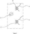
- the inflatable pool may include a pool body 1, a base 2 and an elastic component 3.
- the pool body 1 may include an annular body 11 and a bottom wall 12 connected with the annular body 11, and the annular body 11 may be configured with a first air chamber.
- a pool boundary 1 a may be disposed on the annular body 11 and the bottom wall 12, and the pool boundary may include a first boundary disposed on a first side of the annular body and a second boundary disposed on a second side of the annular body.
- the annular body 11 when the inflatable pool is put in use, the annular body 11 can be filled with air, which will make the annular body 11 be inflated and have a shape of an annular tube, so that the first air chamber is formed. Further, the annular body 11 together with the bottom wall 12 defines the boundary of the pool 1 a, wherein the bottom wall 12 serves as a bottom of the pool 1 a, and the annular body 11 serves as a sidewall of the pool 1 a.
- the inflatable pool may include a pair of bases 2 which are spaced along a circumferential direction F of the annular body 11, wherein the bases 2 may be disposed on an end portion of the annular body 11 opposite to the bottom wall 12.
- an elastic component 3 can be disposed between the pair of bases 2 along the circumferential direction F of the annular body to form a shooting device.
- a window 2a can be defined between these two bases 2, and the elastic component 3 can be disposed in the window 2a.
- the inflatable pool may include a target device 4.
- the target device 4 may be disposed along a radial direction of the annular body to face the shooting device.
- the user when the inflatable pool is put in use, firstly, the user can fill the pool 1 a with water. Thereafter, the user can lie in the pool 1 a with his/her back against the annular body 11 and face the window 2a, so as to shoot play balls 5 into the target device 4 (e.g., along a shooting direction shown as arrow f in Figure 1 ) using the elastic component 3, which will increase amusement of the inflatable pool. Therefore, embodiments of the present disclosure provide an inflatable pool having a new profile which can meet user's needs for entertainment.
- the target device 4 and the pool body 1 may be two independent components which are not connected together. Accordingly, when the inflatable pool is put in use, the user can place the target device 4 in front of the pool body 1; and when the inflatable pool is out of use, the user can pick up the target device 4. Therefore, the inflatable pool is easy to use.
- the target device 4 may include a target body 40 confining a central recess 4a.
- the central recess 4a can serve as a destination of the aiming, that is, the user can shoot the play balls 5 into the central recess 4a.
- the target body 40 may be inflatable which has an air chamber. In this case, when the inflatable pool is put in use, the user can fill the target body 40 with air to form an inflated target body 40; and when the inflatable pool is out of use, the user can deflate the target body 40 which will make the target body 40 small in volume, easy to fold and store.
- a bottom portion of the central recess 4a may be provided with a handle (not shown in Figure 1 ). In such a way, the user can lift the target device 4 by holding the handle.
- the structure and shape of the target device as recited above are just for exemplary illustration.
- the target device may be configured into any other structure or shape.
- the target device and the pool body may be connected together by a way such as welding or adhesive bonding, which will make the inflatable pool compact in structure.
- the inflatable pool may not include the target device.
- the user can randomly select an object as the target device for implementing the aiming and shooting actions.
- the annular body 11 may include: a first top annular piece 110, an inner annular piece 111 and an outer annular piece 112 surrounding the inner annular piece 111.
- the inner annular piece 111 and the outer annular piece 112 can be disposed between the first top piece 110 and the bottom wall 12, and be connected with the first top piece 110 and the bottom wall 12, respectively.
- a boundary of the first air chamber can include a part of the bottom wall 12 between the inner annular piece 111 and the outer annular piece 112, the inner annular piece 111, the outer annular piece 112 and the first top piece 110.
- a lower edge of the inner annular piece 111 and a lower edge of the outer annular piece 112 are connected with the bottom wall 12, thus the inner annular piece 111 and the outer annular piece 112 form a lower annular connection region with the bottom wall 12, respectively.
- An upper edge of the inner annular piece 111 and an upper edge of the outer annular piece 112 are connected with the first upper piece 110, thus the inner annular piece 111 and the outer annular piece 112 form an upper annular connection region with the first upper piece 110, respectively.
- a boundary of the first air chamber includes a part of the bottom wall 12 between the inner annular piece 111 and the outer annular piece 112, the inner annular piece 111, the outer annular piece 112 and the first top piece 110, and the two upper annular connection regions and the two lower annular connection regions seal the first air chamber.
- the first top piece 110, the bottom wall 12, the inner annular piece 111 and the outer annular piece 112 may be manufactured independently and then be connected together to form the first air chamber.
- first top piece 110, the bottom wall 12, the inner annular piece 111 and the outer annular piece 112 may be connected by a way of welding.
- both the inner annular piece 111 and the outer annular piece 112 can be connected with the first top piece 110 by the way of welding, and both the inner annular piece 111 and the outer annular piece 112 are connected with the bottom wall 12 by the way of welding.
- both the upper annular connection regions and the lower annular connection regions are a welding region.
- both the annular body 11 and the bottom wall 12 are made of plastic.
- the way of welding is a plastic welding process.
- the plastic welding process is suitable for components which are not able to be connected by thermal fusion welding and ultrasonic welding, such as components made of PE (Polyethylene), PP (Polypropylene), nylon or PET (Polyethylene Terephthalate).
- the plastic welding is a method of bonding two components together within a short period of time by rotating the two components in high speed and pressing the two components.
- the plastic welding process may soften the components by an external heat source, by a mechanical movement, or by an electromagnetic way.
- a welding width formed by the way of welding may be not greater than 5cm. In such a way, the welding width is small and the welding region is not noticeable, which will improve an appearance of the inflatable pool.
- the annular body may not include the first top piece.
- the upper edges of the inner annular piece and the outer annular piece are welded together to configure the first air chamber.
- first top piece, the bottom wall, the inner annular piece and the outer annular piece may be connected together by a way of adhesive bonding to configure the boundary of the first air chamber.
- the outer annular piece 112 is provided with an air valve 113, wherein the first air chamber can be inflated or deflated via the air valve 113.
- the base 2 may be an inflatable structure having a second air chamber.
- the base 2 can be plasticity, so that the base 2 can be inflated and deflated.
- the base 2 may include a second top piece 20, a first inner piece 21 and a first outer piece 22.
- the first inner piece 21 and the first outer piece 22 can be disposed between the annular body 11 and the second top piece 20, and the first inner piece 21 can be positioned closer to an inner side of the annular body 11 than the first outer piece 22.
- the first inner piece 21, the first outer piece 22, the annular body 11 and the second top piece 20 can be connected to form a second air chamber to be configured to the bases 2. That is to say, when the inflatable pool is put in use, the base 2 can be filled with air, so that the base 2 will be inflated to form the second air chamber. Correspondingly, when the base 2 is not filled with air, the base 2 is in a compressed status.
- the first inner piece 21 and the first outer piece 22 can be fixed to the annular body 11 via the first top piece 110.
- a first bottom edge of the first inner piece 21 and a first bottom edge of the first outer piece 22 can be connected with the first top piece 110 of the annular body 11 to form a bottom annular connection region. Thereafter, a first top edge of the first inner piece 21 and a first top edge of the first outer piece 22 can be connected to the second top piece 20 to form a top annular connection region. Further, side edges of the first inner piece 21 and the first outer piece 22 are connected to form side connection regions. In such a way, the first inner piece 21, the first outer piece 22 and a part of the annular body 11 between the first inner piece 21 and the first outer piece 22 define the second air chamber, wherein the bottom annular connection region, the top annular connection region and the side connection regions seal the second air chamber.
- the first inner piece 21, the first outer piece 22, the annular body 11 and the second top piece 20 are connected by a way of welding.
- the first inner piece 21 and the first top piece 110, the first outer piece 22 and the first top piece 110, the first inner piece 21 and the second top piece 20, the first outer piece 22 and the second top piece 20, and the first inner piece 21 and the first outer piece 22 are all connected by the way of welding.
- the bottom annular connection region, the top annular connection region and the side connection regions are all welding regions.
- a welding width formed by the way of welding is not greater than 5cm, so that the welding regions are small in dimension and not noticeable, which will improve an appearance of the inflatable pool.
- the first inner piece 21 or the first outer piece 22 is provided with an air valve 23, wherein the base 2 can be inflated or deflated via the air valve 23.
- the base 2 and the annular body 11 are welded to form an assembly, which will enhance an integration level of the inflatable pool. Further, the base 2 is light, small in volume and easy to store when being deflated. In some embodiments, the base may be configured into a solid structure.
- the base may only include the first inner piece and the first outer piece, but not the second top piece. In this case, after the first inner piece and the first outer piece are welded to the annular body, edges of the first inner piece and the first outer piece are connected to define the boundary of the second air chamber.
- the elastic component 3 may include a rubber band 31 and a pouch 32, wherein the pouch 32 can be connected to the rubber band 31.
- the base 2 can include a plurality of snap rings 24, wherein two ends of the rubber band 31 are respectively connected to the snap rings 24 on two bases 2 which are neighboring to each other along the circumferential direction F. In such a way, the elastic component 3 is fixed to the two bases 2 which are neighboring to each other along the circumferential direction F.
- the rubber band 31 has elasticity, and the pouch 32 is used to hold the play ball 5.
- the snap rings 24 serve as anchor points of the elastic component 3, and the rubber band 31 is fastened to the snap rings 24.
- each elastic component 3 may include two rubber bands 31, and the pouch 32 is connected to the two rubber bands 31. Specifically, the two rubber bands 31 pass through two sides of the pouch 32, respectively, so that the pouch 32 is connected to the rubber bands 31.
- an end of the rubber band 31 can passes through the snap ring 24 and be fastened to the snap ring 24, so as to fix the elastic component 3 to the snap ring 24; and when the elastic component 3 is not in use, the rubber band 31 can be detached from the snap ring 24, so as to take the elastic component 3 down. Therefore, the elastic component 3 can be easily fixed to or detached from the base 2, which is convenient to use.
- the inflatable pool may include two bases 2 and one elastic component 3. In some embodiments, the inflatable pool may include more than two bases. In this case, between each two of the multiple bases which are neighboring to each other along the circumferential direction, an elastic component can be arranged. Therefore, the number of the elastic component is more than one. In such a way, when the inflatable pool is put in use, multiple users can use different elastic components in a common inflatable pool to shoot at the same time.
- the inflatable pool may include at least two bases along the circumferential direction of the annular body.
- the inflatable pool further includes a supporting member 6, wherein the supporting member 6 can be positioned to face the bases 2 and fastened to one end of the annular body 11 opposite to the bottom wall 12.
- a window 2a is defined between two neighboring bases 2, wherein the supporting member 6 faces the window 2a and the elastic component 3 in the window 2a. Accordingly, when the inflatable pool is put in use, the user can put his/her back against the supporting member 6 and face the window 2a to shoot, which will make it more comfortable for the user to use the inflatable pool.
- the supporting member 6 extends along the circumferential direction F.
- the supporting member 6 has a length along the circumferential direction F greater than a width, and the supporting member 6 can provide sufficient support for the user's back.
- the supporting member 6 may include an accommodating groove 6a for containing a plurality of play balls, wherein the accommodating groove 6a may be opposite to the annular body 11. Accordingly, the supporting member 6 is not only able to provide a support for the user's back, but also able to provide the accommodating groove 6a for containing the play balls 5, which makes it easy and convenient for the user to collect and fetch the play balls 5.
- the supporting member 6 may include a supporting body 60 and an accommodating body 61 with the accommodating groove 6a.
- the supporting body 60 may be fixed to the end of the annular body 11 opposite to the bottom wall 12.
- the accommodating body 61 may be fixed to an end of the supporting body 60 opposite to the annular body 11.
- the accommodating groove 6a is opposite to the supporting body 60.
- the supporting body 60 and the accommodating body 61 define the supporting member 6.
- the supporting body 60 may be fixed to the first top piece 110 of the annular body 11.
- the annular body 11 provides main support for the user's back.
- the accommodating groove 6a is formed in the accommodating body 61.
- the supporting member may only include the accommodating body, but not the supporting body.
- the accommodating body is not only used to accommodate the play balls, but also used to provide a support for the user's back.
- the supporting body 60 may include a third top piece 601, a second inner piece 602 and a second outer piece 603.
- the second inner piece 602 and the second outer piece 603 may be disposed between the annular body 11 and the third top piece 602.
- the second inner piece 602 may be positioned closer to an inner side of the annular body 11 than to the second outer piece 603.
- the second inner piece 602, the second outer piece 603, the annular body 11 and the third top piece 601 are connected to form a third air chamber to be configured to the supporting body 60.
- the supporting body 60 is filled with air to inflate the supporting body 60, so as to form the third air chamber.
- the supporting body 60 is not filled with air, the supporting body is compressed.
- the annular body 11 may be connected with the second inner piece 602 and the second outer piece 603 via the first top piece 110.
- a second top edge of the second inner piece 602 and a second top edge of the second outer piece 603 can be connected to the third top piece 601
- a second bottom edge of the second inner piece 602 and a second bottom edge of the second outer piece 603 can be connected to the first top piece 110
- side edges of the second inner piece 602 and side edges of the second outer piece 603 can be connected.
- the supporting body 60 is an inflatable structure, which is easy to use.
- the second inner piece 602 or the second outer piece 603 may be provided with an air valve (not shown) for inflating or deflating the supporting body 60.
- the second inner piece 602 and the third top piece 601, the second outer piece 603 and the third top piece 601, the second inner piece 602 and the first top piece 110, the second outer piece 603 and the first top piece 110, and the second inner piece 602 and the second outer piece 603 are all connected by a way of welding.
- a welding width formed by the way of welding is not greater than 5cm, so that an area of the welding region is small and the inflatable pool has an improved appearance.
- the supporting body may only include the second inner piece and the second outer piece, but not the third top piece. In this case, edges of the second inner piece and the second outer piece are connected to form the supporting body with the third air chamber.
- the accommodating body 61 may include an inner body 611 and an outer body 612.
- the inner body 611 may be positioned closer to the inner side of the annular body 11 than to the outer body 612.
- Each two of the inner body 611, the outer body 612 and the supporting body 60 may be connected to define the accommodating groove 6a.
- the inner body 611 and the outer body 612 are fixed to the supporting body 60 via the third top piece 601.
- the third top piece 601 serves as a bottom of the accommodating groove 6a.
- the inner body 611 and the outer body 612 may be arranged opposite to each other. Both the inner body 611 and the outer body 612 include two ends extending along the circumferential direction F. The inner body 611 and the outer body 612 can be connected along the circumferential direction F of the annular body at a same side of an end portion to form the accommodating groove 6a.
- the accommodating body 61 may include the accommodating groove 6a, wherein the accommodating groove 6a is defined by the inner body 611 and the outer body 612.
- the inner body 611 and the outer body 612 are both inflatable.
- the inner body 611 and the outer body 612 may be configured into a tubular-shaped structure having two openings at the ends. Thereafter, the ends of the inner body 611 and the ends of the outer body 612 at the same side along the circumferential direction F are welded, respectively.
- the arc chamfer a is a smooth transition and does not include a shape edge, which will avoid injures caused to the user and will improve the appearance of the inflatable pool.
- the accommodating body 61 may include at least one circular arc boundary having an arc length of a curve in a range between 5cm to 10cm, so that the accommodating body 61 is sufficient to accommodate the play balls 5 and meanwhile is able to provide a comfort support for the user.
- the accommodating body 61 is arc-shaped and has a central angle ranging from 30o to 60o, so that the length of the accommodating body 61 is confined.
- the inner body 611, the outer body 612 and the supporting body 60 are welded to be configured to the accommodating body 61.
- Embodiments of the present disclosure also provide a method for forming an inflatable pool.
- Figure 5 is a flow chart of the method for forming an inflatable pool according to one embodiment of the present disclosure. Referring to Figure 1 and Figure 5 , the method for forming an inflatable pool can include following steps from step S1 to step S3.
- step S1 providing a pool body 1, the pool body 1 including an annular body 11; welding a bottom wall 12 to the annular body 11 to form a first chamber, the first chamber having a first pool boundary and second pool boundary.
- step S2 welding a pair of bases 2 to an end portion of the annular body 11 opposite to the bottom wall 12 along a circumferential direction F of the annular body.
- step S3 providing an elastic component 3 fastened between the pair of bases 2 along the circumferential direction F of the annular body 11 to form a shooting device.
- welding the bases 2 to the annular body 11 may include: softening a welding region of the base 2; and bonding the base 2 to the annular body 11, where the base 2 is welded to the annular body 11 after the welding region of the base 2 is solidified. Accordingly, the welding process is easy.
- the base 2 and the annular body 11 may be welded by a way of plastic welding.
- providing the pool body 1 may include: providing an inner annular piece 111 and an outer annular piece 112 surrounding the inner annular piece 111; welding a first inner edge of the inner annular piece 111 and a first outer edge of the outer annular piece 112 on the bottom wall 12; and welding a first top annular piece 110 on a second inner edge of the inner annular piece 111 and a second outer edge of the outer annular piece112, wherein, a first pool boundary is formed between the first inner edge and the bottom wall 12, and wherein, the second pool boundary is formed between the first outer edge and the bottom wall 12.
- the annular body 11 is formed by the inner annular piece 111, the outer annular piece 112 and the first top piece 110, and a part of the bottom wall 12 between the inner annular piece 111 and the outer annular piece 112, the inner annular piece 111, the outer annular piece 112 and the first top piece 110 define the boundary of the first air chamber.
- an air valve 113 may be formed on the outer annular piece 112.
- the inner annular piece 111, the outer annular piece 112, the first top piece 110 and the bottom wall 12 may be connected by a way of welding.
- a welding width formed by the way of welding may be not greater than 5cm.
- forming the annular body 11 on the bottom wall 12 may include: forming the inner annular piece 111 and the outer annular piece 112 surrounding the inner annular piece 111, on the bottom wall 12; and connecting each two of the inner annular piece 111, the outer annular piece 112 and the bottom wall 12 to form the boundary of the first air chamber.
- welding the pair of base 2 may include: welding a first inner piece 21 and a first outer piece 22 on the annular body 11, the first inner piece 21 may be positioned closer to an inner side of the annular body 11 than to the first outer piece 22; and welding a second top piece 20 on the first inner piece 21 and the first outer piece 22 to form a second chamber, wherein the first inner piece 21 and the first outer piece 22 are located between the annular body 11 and the second top piece 20; and connecting the first inner piece 21, the first outer piece 22, the annular body 11 and the second top piece 20, so as to form the base 2 with the second air chamber.
- an air valve 23 and a snap ring 24 may be welded to the first outer piece 22, where the air valve 23 is used to inflate or deflate the base 2, and the snap ring 24 is used to connect with a rubber band 31 of the elastic component 3. Accordingly, when the inflatable pool is put in use, the elastic component 3 can be connected between two neighboring bases 2 by connecting the rubber band 31 with the snap ring 24.
- first inner piece 21, the first outer piece 22, the annular body 11 and the second top piece 20 are connected by a way of welding.
- a welding width formed by the way of welding is not greater than 5cm.
- the method for forming the inflatable pool may further include: providing a supporting member 6 to face the pair of bases and fastened to one end of the annular body 11 opposite to the bottom wall 12, wherein the supporting member 6 may be fixed to the annular body 11 and faces the window 2a and the elastic component 3 in the window 2a.
- the supporting member 6 increases a height of the annular body 11, so that the supporting member 6 can provide a support to the user's back when the user faces the window to shoot, which will improve a comfort of the inflatable pool.
- the supporting member 6 may extend along the circumferential direction F.
- the supporting member 6 has a length along the circumferential direction F greater than a width thereof, so that the supporting member 6 can provide sufficient support for the user.
- the supporting member 6 may include an accommodating groove 6a for containing a plurality of play balls, wherein the accommodating groove 6a may be positioned opposite to the annular body 11.
- the supporting member 6 is not only able to provide a support for the user's back, but also able to provide the accommodating groove 6a for accommodating the play balls 5.
- providing the supporting member 6 may include: welding a supporting body 60on the end of the annular body 11 opposite to the bottom wall 12; and welding an accommodating body 61 for forming the accommodating groove on an end of the supporting body 60 opposite to the annular body 11 and the accommodating groove 6a is opposite to the supporting body 60.
- the supporting body 60 is fixed to the first top piece 110, and the supporting body 60 is used to provide a support for the user's back.
- welding the supporting body 60 may include: welding a second inner piece 602 and a second outer piece 603on the end of the annular body 11 opposite to the bottom wall 12, and the second inner piece 602 is closer to an inner side of the annular body 11 than the second outer piece 603; welding a third top piece 601on the second inner piece 602 and the second outer piece 603 to form a third air chamber.
- the second inner piece 602, the second outer piece 603, the annular body 11 and the third top piece 601 are connected together, so as to form the supporting body 60 with a third air chamber.
- the second inner piece 602 and the second outer piece 603 are fixed to the first top piece 110 of the annular body 11.
- the supporting body 60 is an inflatable structure and can form the third air chamber when being inflated, which makes the supporting body 60 easy to use and have an improved comfort.
- the second inner piece 602, the second outer piece 603, the annular body 11 and the third top piece 601 may be connected by a way of welding.
- welding the accommodating body 61 may include: providing an inner body 611 and an outer body 612; and welding the inner body 611 and the outer body 612 on the supporting body 60 to form the accommodating groove 6a, wherein, the inner body 611 may be positioned closer to an inner side of the annular body 11 than to the outer body 612, wherein, the inner body 11 and the outer body 612 are welded same side of an end portion on the supporting body 60 along the circumferential direction of the annular body 11, and wherein, the accommodating body 61 may include at least one circular arc boundary having an arc length of a curve in a range between 5cm to 10cm with a central angle of 30 to 60.
- the inner body 611 and the outer body 612 are arranged opposite to each other. Both the inner body 611 and the outer body 612 include two ends along the circumferential direction F and extend from a head end to a tail end. The ends of the inner body 611 and the ends of the outer body 612 which are located in same sides along the circumferential direction F are connected, respectively, for example, the head end of the inner body 611 and the head end of the outer body 612 are connected, and the tail end of the inner body 611 and the tail end of the outer body 612 are connected, so as to form the accommodating groove 6a.
- each two of the inner body 611, the outer body 612 and the supporting body 60 are connected by a way of welding, which is easy to implement.
- both the inner body 611 and the outer body 612 may be inflatable.
Landscapes
- Engineering & Computer Science (AREA)
- Mechanical Engineering (AREA)
- Health & Medical Sciences (AREA)
- General Health & Medical Sciences (AREA)
- Physical Education & Sports Medicine (AREA)
- Architecture (AREA)
- Civil Engineering (AREA)
- Structural Engineering (AREA)
- Massaging Devices (AREA)
- Toys (AREA)
Applications Claiming Priority (1)
| Application Number | Priority Date | Filing Date | Title |
|---|---|---|---|
| CN201720162355.XU CN206477626U (zh) | 2017-02-22 | 2017-02-22 | 充气水池 |
Publications (1)
| Publication Number | Publication Date |
|---|---|
| EP3366867A1 true EP3366867A1 (de) | 2018-08-29 |
Family
ID=59034491
Family Applications (1)
| Application Number | Title | Priority Date | Filing Date |
|---|---|---|---|
| EP17174811.4A Withdrawn EP3366867A1 (de) | 2017-02-22 | 2017-06-07 | Aufblasbares schwimmbecken und verfahren zur herstellung davon |
Country Status (3)
| Country | Link |
|---|---|
| US (1) | US20180238068A1 (de) |
| EP (1) | EP3366867A1 (de) |
| CN (1) | CN206477626U (de) |
Cited By (1)
| Publication number | Priority date | Publication date | Assignee | Title |
|---|---|---|---|---|
| CN116791946A (zh) * | 2023-02-20 | 2023-09-22 | 浙江威邦科技股份有限公司 | 一种带有康复训练功能的泳池 |
Families Citing this family (1)
| Publication number | Priority date | Publication date | Assignee | Title |
|---|---|---|---|---|
| CN215443337U (zh) * | 2021-08-03 | 2022-01-07 | 上海荣威塑胶工业有限公司 | 便携式地上水池 |
Citations (5)
| Publication number | Priority date | Publication date | Assignee | Title |
|---|---|---|---|---|
| US5772535A (en) * | 1996-11-19 | 1998-06-30 | Murphy; John Kenneth | Inflatable portable game |
| US20050000567A1 (en) * | 2003-07-03 | 2005-01-06 | Hsin-Tsai Wu | Inflatable container with a water draining device |
| US20060021125A1 (en) * | 2004-06-18 | 2006-02-02 | Berenson Steven M | Swimming pool having adjustable sunshade |
| US7037220B1 (en) * | 2002-04-22 | 2006-05-02 | Gordon Donald W | Sports play pool |
| WO2015010058A2 (en) * | 2013-07-18 | 2015-01-22 | Intex Recreation Corp. | Inflatable spa |
-
2017
- 2017-02-22 CN CN201720162355.XU patent/CN206477626U/zh not_active Expired - Fee Related
- 2017-06-06 US US15/615,450 patent/US20180238068A1/en not_active Abandoned
- 2017-06-07 EP EP17174811.4A patent/EP3366867A1/de not_active Withdrawn
Patent Citations (5)
| Publication number | Priority date | Publication date | Assignee | Title |
|---|---|---|---|---|
| US5772535A (en) * | 1996-11-19 | 1998-06-30 | Murphy; John Kenneth | Inflatable portable game |
| US7037220B1 (en) * | 2002-04-22 | 2006-05-02 | Gordon Donald W | Sports play pool |
| US20050000567A1 (en) * | 2003-07-03 | 2005-01-06 | Hsin-Tsai Wu | Inflatable container with a water draining device |
| US20060021125A1 (en) * | 2004-06-18 | 2006-02-02 | Berenson Steven M | Swimming pool having adjustable sunshade |
| WO2015010058A2 (en) * | 2013-07-18 | 2015-01-22 | Intex Recreation Corp. | Inflatable spa |
Cited By (1)
| Publication number | Priority date | Publication date | Assignee | Title |
|---|---|---|---|---|
| CN116791946A (zh) * | 2023-02-20 | 2023-09-22 | 浙江威邦科技股份有限公司 | 一种带有康复训练功能的泳池 |
Also Published As
| Publication number | Publication date |
|---|---|
| US20180238068A1 (en) | 2018-08-23 |
| CN206477626U (zh) | 2017-09-08 |
Similar Documents
| Publication | Publication Date | Title |
|---|---|---|
| US5037084A (en) | Adjustable exercising step | |
| US4901998A (en) | Multi-functional activity table | |
| EP3736028B1 (de) | Rutsche, aufblasbare wasserrutsche und schwimmbecken | |
| US9574362B2 (en) | Inflatable pool with drawing board | |
| US3816957A (en) | Connecting means for connecting relatively soft parts of a doll | |
| US2878858A (en) | Bowl shaped play thing | |
| EP3366867A1 (de) | Aufblasbares schwimmbecken und verfahren zur herstellung davon | |
| CN214436419U (zh) | 一种特技踏板车 | |
| US9345920B2 (en) | Fitness hoop having variable impact force | |
| JP2008506429A (ja) | ボール表皮 | |
| KR101020572B1 (ko) | 튜브형 썰매 | |
| US11130070B2 (en) | Snowman making apparatus | |
| US5679082A (en) | Saucer-shaped water skipping device | |
| JP5578433B2 (ja) | 遊戯用マット及びそれを用いた遊具 | |
| US20060021125A1 (en) | Swimming pool having adjustable sunshade | |
| US6511403B2 (en) | Rotating play device capable of training wrist coordination | |
| WO2020001664A3 (zh) | 一种吹泡泡装置 | |
| ES1070082U (es) | Ficha botadora de juguete. | |
| CN208130428U (zh) | 一种幼儿羽毛球训练装置 | |
| CN218187827U (zh) | 一种用于收纳国际象棋的象棋台及国际象棋收纳盒 | |
| CN201500439U (zh) | 拼图玩具组件及拼图玩具 | |
| KR200487846Y1 (ko) | 골프백 | |
| US20150265936A1 (en) | Multipurpose recreational toy for converting a balloon to an item used in sports | |
| CN106178480A (zh) | 一种娱乐健身装置 | |
| CN209920901U (zh) | 绣球结构 |
Legal Events
| Date | Code | Title | Description |
|---|---|---|---|
| PUAI | Public reference made under article 153(3) epc to a published international application that has entered the european phase |
Free format text: ORIGINAL CODE: 0009012 |
|
| 17P | Request for examination filed |
Effective date: 20180405 |
|
| AK | Designated contracting states |
Kind code of ref document: A1 Designated state(s): AL AT BE BG CH CY CZ DE DK EE ES FI FR GB GR HR HU IE IS IT LI LT LU LV MC MK MT NL NO PL PT RO RS SE SI SK SM TR |
|
| AX | Request for extension of the european patent |
Extension state: BA ME |
|
| RIC1 | Information provided on ipc code assigned before grant |
Ipc: E04H 4/00 20060101AFI20190425BHEP |
|
| GRAP | Despatch of communication of intention to grant a patent |
Free format text: ORIGINAL CODE: EPIDOSNIGR1 |
|
| INTG | Intention to grant announced |
Effective date: 20190702 |
|
| STAA | Information on the status of an ep patent application or granted ep patent |
Free format text: STATUS: THE APPLICATION IS DEEMED TO BE WITHDRAWN |
|
| 18D | Application deemed to be withdrawn |
Effective date: 20191113 |