EP3366900A1 - Gasmotor - Google Patents
Gasmotor Download PDFInfo
- Publication number
- EP3366900A1 EP3366900A1 EP15909294.9A EP15909294A EP3366900A1 EP 3366900 A1 EP3366900 A1 EP 3366900A1 EP 15909294 A EP15909294 A EP 15909294A EP 3366900 A1 EP3366900 A1 EP 3366900A1
- Authority
- EP
- European Patent Office
- Prior art keywords
- throat
- diameter
- chamber
- ratio
- nozzle hole
- Prior art date
- Legal status (The legal status is an assumption and is not a legal conclusion. Google has not performed a legal analysis and makes no representation as to the accuracy of the status listed.)
- Granted
Links
Images


Classifications
-
- F—MECHANICAL ENGINEERING; LIGHTING; HEATING; WEAPONS; BLASTING
- F02—COMBUSTION ENGINES; HOT-GAS OR COMBUSTION-PRODUCT ENGINE PLANTS
- F02B—INTERNAL-COMBUSTION PISTON ENGINES; COMBUSTION ENGINES IN GENERAL
- F02B19/00—Engines characterised by precombustion chambers
- F02B19/16—Chamber shapes or constructions not specific to sub-groups F02B19/02 - F02B19/10
- F02B19/18—Transfer passages between chamber and cylinder
-
- F—MECHANICAL ENGINEERING; LIGHTING; HEATING; WEAPONS; BLASTING
- F02—COMBUSTION ENGINES; HOT-GAS OR COMBUSTION-PRODUCT ENGINE PLANTS
- F02B—INTERNAL-COMBUSTION PISTON ENGINES; COMBUSTION ENGINES IN GENERAL
- F02B19/00—Engines characterised by precombustion chambers
- F02B19/10—Engines characterised by precombustion chambers with fuel introduced partly into pre-combustion chamber, and partly into cylinder
- F02B19/1004—Engines characterised by precombustion chambers with fuel introduced partly into pre-combustion chamber, and partly into cylinder details of combustion chamber, e.g. mounting arrangements
- F02B19/1014—Engines characterised by precombustion chambers with fuel introduced partly into pre-combustion chamber, and partly into cylinder details of combustion chamber, e.g. mounting arrangements design parameters, e.g. volume, torch passage cross sectional area, length, orientation, or the like
-
- F—MECHANICAL ENGINEERING; LIGHTING; HEATING; WEAPONS; BLASTING
- F02—COMBUSTION ENGINES; HOT-GAS OR COMBUSTION-PRODUCT ENGINE PLANTS
- F02B—INTERNAL-COMBUSTION PISTON ENGINES; COMBUSTION ENGINES IN GENERAL
- F02B19/00—Engines characterised by precombustion chambers
- F02B19/10—Engines characterised by precombustion chambers with fuel introduced partly into pre-combustion chamber, and partly into cylinder
- F02B19/1019—Engines characterised by precombustion chambers with fuel introduced partly into pre-combustion chamber, and partly into cylinder with only one pre-combustion chamber
- F02B19/108—Engines characterised by precombustion chambers with fuel introduced partly into pre-combustion chamber, and partly into cylinder with only one pre-combustion chamber with fuel injection at least into pre-combustion chamber, i.e. injector mounted directly in the pre-combustion chamber
-
- F—MECHANICAL ENGINEERING; LIGHTING; HEATING; WEAPONS; BLASTING
- F02—COMBUSTION ENGINES; HOT-GAS OR COMBUSTION-PRODUCT ENGINE PLANTS
- F02B—INTERNAL-COMBUSTION PISTON ENGINES; COMBUSTION ENGINES IN GENERAL
- F02B19/00—Engines characterised by precombustion chambers
- F02B19/16—Chamber shapes or constructions not specific to sub-groups F02B19/02 - F02B19/10
-
- F—MECHANICAL ENGINEERING; LIGHTING; HEATING; WEAPONS; BLASTING
- F02—COMBUSTION ENGINES; HOT-GAS OR COMBUSTION-PRODUCT ENGINE PLANTS
- F02B—INTERNAL-COMBUSTION PISTON ENGINES; COMBUSTION ENGINES IN GENERAL
- F02B19/00—Engines characterised by precombustion chambers
- F02B19/12—Engines characterised by precombustion chambers with positive ignition
-
- Y—GENERAL TAGGING OF NEW TECHNOLOGICAL DEVELOPMENTS; GENERAL TAGGING OF CROSS-SECTIONAL TECHNOLOGIES SPANNING OVER SEVERAL SECTIONS OF THE IPC; TECHNICAL SUBJECTS COVERED BY FORMER USPC CROSS-REFERENCE ART COLLECTIONS [XRACs] AND DIGESTS
- Y02—TECHNOLOGIES OR APPLICATIONS FOR MITIGATION OR ADAPTATION AGAINST CLIMATE CHANGE
- Y02T—CLIMATE CHANGE MITIGATION TECHNOLOGIES RELATED TO TRANSPORTATION
- Y02T10/00—Road transport of goods or passengers
- Y02T10/10—Internal combustion engine [ICE] based vehicles
- Y02T10/12—Improving ICE efficiencies
Definitions
- the present disclosure relates to a spark ignition precombustion-chamber type gas engine, especially to a spark ignition precombustion-chamber type gas engine with a precombustion chamber having a characteristic shape.
- a spark ignition precombustion-chamber type gas engine has been known as a gas engine capable of efficient combustion of lean mixed gas.
- a typical spark ignition precombustion-chamber type gas engine includes a main combustion chamber formed above a piston inside a cylinder, and a precombustion chamber disposed in the upper section of the cylinder. Mixed gas inside the precombustion chamber is combusted, and combustion flame is injected from a nozzle hole disposed on the lower part of the precombustion chamber, whereby lean mixed gas inside the main combustion chamber is combusted.
- the precombustion chamber fuel gas supply valve also closes. Further, the lean mixed gas introduced into the cylinder is compressed as the piston rises, and a part of the lean mixed gas flows into the precombustion chamber through the precombustion chamber nozzle hole. Due to such an inflow of lean mixed gas, the lean mixed gas from the main chamber and the precombustion fuel gas are mixed in the precombustion chamber, thus reaching a density suitable for ignition.
- the mixed gas in the precombustion chamber is ignited at a predetermined timing with an ignition plug disposed in the precombustion chamber, the mixed gas in the precombustion chamber is combusted, and combustion flame is injected into the cylinder through the precombustion chamber nozzle hole. Due to such injection of combustion flame, the lean mixed gas inside the cylinder is ignited, and is eventually combusted.
- a spark ignition precombustion-chamber type gas engine mixed gas having a density suitable for ignition is formed in the precombustion chamber to perform ignition, and combustion flame is injected into the cylinder from the precombustion chamber, whereby it is possible to combust lean mixed gas, which is rather less combustible, efficiently.
- a spark ignition precombustion-chamber type gas engine it is possible to achieve a high efficiency and clean exhaust gas.
- Patent Document 1 JP2003-286849 (see FIG. 4 )
- Patent Document 1 does not disclose the shape of the nozzle hole, such as the inner diameter and the length of the nozzle hole, in detail.
- an object of at least some embodiments of the present invention is to provide an engine including a nozzle hole whereby mixed gas can flow stably from the main chamber to the precombustion chamber.
- a gas engine includes: a main combustion chamber; and a precombustion chamber including an ignition plug disposed in a precombustion-chamber upper section and a throat formed in a precombustion-chamber lower section, the throat including a nozzle hole, configured such that mixed gas flows into the throat of the precombustion chamber via the nozzle hole from the main combustion chamber in a compression stroke.
- the nozzle hole has an opening edge portion on a throat side, the opening edge portion including a curved surface portion formed along a peripheral edge of the opening edge portion.
- the throat extends linearly along a center axis of the precombustion chamber.
- a ratio of a length of the throat to an inner diameter of the throat is not smaller than 1.6 and not greater than 2.6, and a value obtained by multiplying a ratio of the inner diameter of the throat to a radius of the curved surface portion by a ratio of the inner diameter of the throat to a precombustion chamber upper portion diameter is not smaller than 18.
- the curved surface portion is formed along the periphery of the throat-side opening edge portion of the nozzle hole, and thus it is possible to suppress rapid diffusion of mixed gas when mixed gas is discharged from the nozzle hole into the throat, which makes it possible to suppress separation of mixed gas in the nozzle hole.
- the throat extends linearly along the center axis of the precombustion chamber, and the ratio of the length of the throat to the inner diameter of the throat is not smaller than 1.6 and not greater than 2.6. Accordingly, it is possible to suppress the risk of occurrence of turbulence in the flow of mixed gas injected into the throat, and make it no longer necessary to change the position of the ignition plug.
- a value obtained by multiplying a ratio of the inner diameter of the throat to the radius of the curved surface portion by a ratio of the throat diameter to the precombustion chamber upper portion diameter is not smaller than 18, and thereby it is possible to stabilize a flow of mixed gas in the precombustion chamber and suppress deterioration of combustion variation.
- a value obtained by multiplying a ratio of a length of the nozzle hole to a diameter of the nozzle hole by a ratio of the inner diameter of the throat to the precombustion chamber upper portion diameter is not smaller than 1.4.
- a gas engine including a nozzle hole whereby mixed gas can flow stably from the main chamber to the precombustion chamber.
- FIGs. 1 to 4 Embodiments of a gas engine of the present invention will now be described with reference to FIGs. 1 to 4 . It is intended, however, that unless particularly specified, dimensions, materials, shapes, relative positions and the like of components described in the embodiments shall be interpreted as illustrative only and not intended to limit the scope of the present invention.
- the gas engine 1 includes a cylinder 3, a cylinder head 7 disposed on the upper portion of the cylinder 3, and a piston 5 disposed inside the cylinder 3 so as to be movable in the up-down direction.
- a main combustion chamber 10 is formed in a region surrounded by the upper surface of the piston 5, the inner surface of the cylinder 3, and the lower surface of the cylinder head 7.
- An intake port 13 for supplying fuel is connected to the cylinder head 7, such that fuel supply to the main combustion chamber 10 is controlled through opening and closing of the intake valve 14 disposed on the cylinder head 7.
- an exhaust port 17 for discharging exhaust gas is connected to the cylinder head 7, such that discharge of exhaust gas from the main combustion chamber 10 is controlled through opening and closing of the exhaust valve 18 disposed on the cylinder head 7.
- a precombustion chamber body 30 including a precombustion chamber 31 is disposed on the substantially center part of the upper portion of the cylinder head.
- the precombustion chamber body 30 extends in the up-down direction and has a bottomed container shape, including a precombustion chamber 31 formed inside, extending in the up-down direction.
- An ignition plug 40 is disposed on the upper portion of the precombustion chamber 31.
- the precombustion chamber body 30 includes a precombustion chamber fuel gas passage 34 for supplying the precombustion chamber 31 with fuel.
- the fuel injected through the precombustion chamber fuel gas passage 34 is mixed with mixed gas supplied to the precombustion chamber 31 through a nozzle hole 37 described below from the main combustion chamber 10 in the compression stroke.
- the volume of the precombustion chamber 31 is smaller than the volume of the main combustion chamber 10.
- the precombustion chamber 31 includes: a throat 32 extending upward from the bottom portion of the precombustion chamber body 30 and having a bottomed cylindrical shape; and an upper precombustion chamber 33 including a diameter widening portion 33a connected to the upper end of the throat 32 and extending upward, with its diameter increasing gradually upward, and a cylindrical portion 33b connected to the upper end of the diameter widening portion 33a and having a cylindrical shape.
- the precombustion chamber 31 is formed symmetrically with respect to the center axis line.
- the above described ignition plug 40 is disposed on the upper precombustion chamber 33.
- a plurality of nozzle holes 37 are disposed at predetermined intervals, penetrating through the throat 32 between the outer surface 30a of the precombustion chamber body 30 and the inner surface 32a of the throat 32.
- the nozzle holes 37 are inclined downward from the center side toward the radially outer side of the precombustion chamber body 30.
- the nozzle holes 37 extend linearly and each include end portions with respect to the axial direction. An end portion of each nozzle hole 37 has an opening on the outer surface 30a of the precombustion chamber body 30 and another end portion has an opening on the inner surface 32a of the throat 32. The shape of the nozzle holes 37 will be described below in detail.
- the gas engine 1 In the compression stroke, the gas engine 1 having the above configuration injects mixed gas of the main combustion chamber 10 into the precombustion chamber 31 via the nozzle holes 37, and mixes the mixed gas with fuel injected into the precombustion chamber 31 to achieve a density suitable for ignition. Further, when the piston 5 reaches the vicinity of the compression top dead center, the gas engine 1 ignites mixed gas in the precombustion chamber 31 with the ignition plug 40, and combusts mixed gas in the precombustion chamber 31. Further, combustion flame is injected into the main combustion chamber 10 from the injection nozzle holes 37, and the injected combustion flame ignites the mixed gas in the main combustion chamber 10 to cause combustion.
- the nozzle hole 37 includes a curved surface portion 37a having a curved surface of a predetermined radius R on the opening edge portion on the throat side, formed along the periphery of the opening edge portion.
- the radius R of the curved surface portion 37a has a constant relationship with the inner diameter ⁇ of the throat 32. That is, the throat curved surface 37a is formed such that a value obtained by multiplying a ratio of the inner diameter ⁇ s of the throat 32 (hereinafter, referred to as "throat diameter cps") to the radius R of the curved surface portion 37a by a ratio of the throat diameter ⁇ s to the precombustion chamber upper portion diameter ⁇ n is not smaller than 18.
- Such a curved surface portion 37a can be formed by chamfering the opening edge portion on the throat side along the periphery of the opening edge portion, after forming the nozzle hole 37 by drilling. Furthermore, the curved surface portion 37a may be formed by a method other than the above, for instance, by casting.
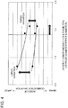
- x-axis represents a value obtained by multiplying a ratio of the throat diameter ⁇ s to the radius R of the curved surface portion 37a of the nozzle hole 37 by a ratio of the throat diameter ⁇ s to the precombustion chamber upper portion diameter ⁇ n (inner diameter of the above described cylindrical portion 33b), and y-axis represents an index of combustion variation inside the precombustion chamber 31.
- the mark " ⁇ " indicates a measurement value
- the solid line indicates a result estimated from a plurality of measurement values.
- the index of combustion variation inside the precombustion chamber 31 on the y-axis shows that combustion variation increases toward the upper side of the y-axis, and decreases toward the lower side of the y-axis.
- FIG. 3 as the value obtained by multiplying a ratio of the throat diameter ⁇ s to the radius R of the curved surface portion 37a of the nozzle hole 37 by a ratio of the throat diameter ⁇ s to the precombustion chamber upper portion diameter ⁇ n becomes smaller than 18, the increase rate of the index of combustion variation increases.
- the precombustion chamber 31 of the present embodiment is formed such that a value obtained by multiplying a ratio of the throat diameter ⁇ s to the radius R of the curved surface portion 37a by a ratio of the throat diameter ⁇ s to the precombustion chamber upper portion diameter ⁇ n is not smaller than 18.
- the throat diameter ⁇ s is relatively large with respect to the radius R of the curved surface portion 37a.
- the throat diameter ⁇ s has a constant relationship with the length L (see FIG. 1 ) of the throat 32. That is, the ratio of the length L of the throat 32 to the throat diameter ⁇ s is not smaller than 1.6 and not greater than 2.6. If the ratio of the length L of the throat 32 to the throat diameter ⁇ s is smaller than 1.6, there is a greater risk of occurrence of turbulence in the flow of mixed gas injected into the throat 32 through the above described nozzle hole 37. On the other hand, if the ratio of the length L of the throat 32 to the throat diameter ⁇ s is greater than 2.6, the throat 32 is too long, and it is necessary to change the position of the ignition plug 40.
- the ratio of the length L' of the nozzle hole 37 to diameter ⁇ h of the nozzle hole 37 has a constant relationship. That is, the value obtained by multiplying a ratio of the length L' of the nozzle hole 37 to the diameter ⁇ h of the nozzle hole 37 is not smaller than 1.4.
- the ratio of the length L' of the nozzle hole 37 to the diameter ⁇ h of the nozzle hole 37 will be described.
- FIG. 4 is a graph showing a relationship between a value obtained by multiplying a ratio of the length L' of the nozzle hole 37 to the diameter ⁇ h of the nozzle hole 37 by a ratio of the throat diameter ⁇ s to the precombustion chamber upper portion diameter ⁇ n and an index of combustion variation inside the precombustion chamber.
- the index of combustion variation inside the precombustion chamber 31 on the y-axis shows that combustion variation increases toward the upper side of the y-axis, and decreases toward the lower side of the y-axis.
- the mark " ⁇ " indicates a measurement value
- the solid line indicates a result estimate from a plurality of measurement values.
- the measurement value has individual variability with respect to combustion variation, and thus there are two solid lines representing the result.
- One solid line represents a greater index and the other solid line represents a smaller index.
- the increase rate of the index of combustion variation increases and the individual variability with respect to combustion variation also increases.
- the nozzle hole 37 is formed such that the value obtained by multiplying a ratio of the length L' of the nozzle hole 37 to the diameter ⁇ h of the nozzle hole 37 by a ratio of the throat diameter ⁇ s to the precombustion chamber upper portion diameter ⁇ n is 1.4.
- the nozzle hole 37 formed as described above it is possible to rectify the flow at the nozzle hole 37 when mixed gas flows into the precombustion chamber 31 from the main combustion chamber 10.
- the flow of mixed gas from the main combustion chamber 10 to the precombustion chamber 31 is stabilized in each engine cycle, and mixed gas having a density that can be easily ignited is formed around the ignition plug 40, and thus it is possible to stabilize combustion inside the precombustion chamber 31 in each cycle.
Landscapes
- Engineering & Computer Science (AREA)
- Chemical & Material Sciences (AREA)
- Combustion & Propulsion (AREA)
- Mechanical Engineering (AREA)
- General Engineering & Computer Science (AREA)
- Combustion Methods Of Internal-Combustion Engines (AREA)
Applications Claiming Priority (1)
| Application Number | Priority Date | Filing Date | Title |
|---|---|---|---|
| PCT/JP2015/083370 WO2017090177A1 (ja) | 2015-11-27 | 2015-11-27 | ガスエンジン |
Publications (3)
| Publication Number | Publication Date |
|---|---|
| EP3366900A1 true EP3366900A1 (de) | 2018-08-29 |
| EP3366900A4 EP3366900A4 (de) | 2018-08-29 |
| EP3366900B1 EP3366900B1 (de) | 2020-02-12 |
Family
ID=58764102
Family Applications (1)
| Application Number | Title | Priority Date | Filing Date |
|---|---|---|---|
| EP15909294.9A Active EP3366900B1 (de) | 2015-11-27 | 2015-11-27 | Gasmotor |
Country Status (3)
| Country | Link |
|---|---|
| US (1) | US20180334950A1 (de) |
| EP (1) | EP3366900B1 (de) |
| WO (1) | WO2017090177A1 (de) |
Cited By (1)
| Publication number | Priority date | Publication date | Assignee | Title |
|---|---|---|---|---|
| WO2020076222A1 (en) * | 2018-10-11 | 2020-04-16 | Scania Cv Ab | A pre-chamber arrangement for a gas engine and a gas engine |
Families Citing this family (2)
| Publication number | Priority date | Publication date | Assignee | Title |
|---|---|---|---|---|
| JP6796471B2 (ja) * | 2016-12-08 | 2020-12-09 | 三菱重工エンジン&ターボチャージャ株式会社 | 副室式ガスエンジン |
| US11415041B2 (en) * | 2019-09-16 | 2022-08-16 | Woodward, Inc. | Flame triggered and controlled volumetric ignition |
Family Cites Families (6)
| Publication number | Priority date | Publication date | Assignee | Title |
|---|---|---|---|---|
| US5024193A (en) * | 1990-02-06 | 1991-06-18 | Caterpillar Inc. | Fuel combustion system, method, and nozzle member therefor |
| JP2002349265A (ja) * | 2001-05-22 | 2002-12-04 | Mitsubishi Heavy Ind Ltd | 副室付ガスエンジンのシリンダヘッド構造 |
| US20130000598A1 (en) * | 2009-12-28 | 2013-01-03 | Kawasaki Jukogyo Kabushiki Kaisha | Divided-chamber gas engine |
| JP5357926B2 (ja) * | 2010-12-27 | 2013-12-04 | 川崎重工業株式会社 | 副室式ガスエンジン |
| JP6049450B2 (ja) * | 2012-12-28 | 2016-12-21 | 三菱重工業株式会社 | 副室式ガスエンジン |
| US9797296B2 (en) * | 2013-03-15 | 2017-10-24 | Cummins Inc. | Pre-chamber for internal combustion engine |
-
2015
- 2015-11-27 EP EP15909294.9A patent/EP3366900B1/de active Active
- 2015-11-27 US US15/777,965 patent/US20180334950A1/en not_active Abandoned
- 2015-11-27 WO PCT/JP2015/083370 patent/WO2017090177A1/ja not_active Ceased
Cited By (3)
| Publication number | Priority date | Publication date | Assignee | Title |
|---|---|---|---|---|
| WO2020076222A1 (en) * | 2018-10-11 | 2020-04-16 | Scania Cv Ab | A pre-chamber arrangement for a gas engine and a gas engine |
| US11261778B2 (en) | 2018-10-11 | 2022-03-01 | Scania Cv Ab | Pre-chamber arrangement for a gas engine and a gas engine |
| US11608772B2 (en) | 2018-10-11 | 2023-03-21 | Scania Cv Ab | Pre-chamber arrangement for a gas engine and a gas engine |
Also Published As
| Publication number | Publication date |
|---|---|
| EP3366900B1 (de) | 2020-02-12 |
| WO2017090177A1 (ja) | 2017-06-01 |
| EP3366900A4 (de) | 2018-08-29 |
| US20180334950A1 (en) | 2018-11-22 |
Similar Documents
| Publication | Publication Date | Title |
|---|---|---|
| EP3061939B1 (de) | Verbrennungsmotor mit einer vorkammer | |
| JP5920317B2 (ja) | 副室式内燃機関 | |
| CN104508276B (zh) | 副室式燃气发动机 | |
| JP5002566B2 (ja) | エンジン及びエンジン用点火プラグ | |
| WO2011080917A1 (ja) | 副室式ガスエンジン | |
| JP6462240B2 (ja) | ガスエンジン | |
| JP6049450B2 (ja) | 副室式ガスエンジン | |
| EP3536923B1 (de) | Gasmotor mit einer hilfskammer | |
| EP3361067A1 (de) | Hilfskammer-motor | |
| EP2975237B1 (de) | Vorkammerbodenabschnitt, vorkammer, zylindervorrichtung, verfahren zum mischen von gas und luft sowie zündung des gas-luft-gemischs in einer vorkammer und verfahren zum ersetzen einer vorkammer | |
| CN105264196B (zh) | 直喷式柴油发动机 | |
| EP3366900B1 (de) | Gasmotor | |
| JP5357926B2 (ja) | 副室式ガスエンジン | |
| US11085361B2 (en) | Precombustion chamber gas engine | |
| JP2020037939A (ja) | プレチャンバ | |
| US20150020766A1 (en) | Prechamber device for an internal combustion engine | |
| JP5122367B2 (ja) | エンジン及びエンジン用点火プラグ | |
| JP5319824B2 (ja) | エンジン及びエンジン用点火プラグ | |
| CN110118120B (zh) | 内燃机 | |
| CN207501146U (zh) | 一种灶具燃烧器 | |
| EP2193263B1 (de) | Verbrennungsmotor | |
| JP5319823B2 (ja) | エンジン及びエンジン用点火プラグ | |
| EP3584423A1 (de) | Ottomotor | |
| JP7571759B2 (ja) | エンジン | |
| CN121701330A (zh) | 发动机 |
Legal Events
| Date | Code | Title | Description |
|---|---|---|---|
| STAA | Information on the status of an ep patent application or granted ep patent |
Free format text: STATUS: THE INTERNATIONAL PUBLICATION HAS BEEN MADE |
|
| PUAI | Public reference made under article 153(3) epc to a published international application that has entered the european phase |
Free format text: ORIGINAL CODE: 0009012 |
|
| STAA | Information on the status of an ep patent application or granted ep patent |
Free format text: STATUS: REQUEST FOR EXAMINATION WAS MADE |
|
| 17P | Request for examination filed |
Effective date: 20180517 |
|
| A4 | Supplementary search report drawn up and despatched |
Effective date: 20180712 |
|
| AK | Designated contracting states |
Kind code of ref document: A1 Designated state(s): AL AT BE BG CH CY CZ DE DK EE ES FI FR GB GR HR HU IE IS IT LI LT LU LV MC MK MT NL NO PL PT RO RS SE SI SK SM TR |
|
| AX | Request for extension of the european patent |
Extension state: BA ME |
|
| DAV | Request for validation of the european patent (deleted) | ||
| DAX | Request for extension of the european patent (deleted) | ||
| STAA | Information on the status of an ep patent application or granted ep patent |
Free format text: STATUS: EXAMINATION IS IN PROGRESS |
|
| 17Q | First examination report despatched |
Effective date: 20190402 |
|
| RIC1 | Information provided on ipc code assigned before grant |
Ipc: F02B 19/12 20060101ALN20190717BHEP Ipc: F02B 19/16 20060101ALI20190717BHEP Ipc: F02B 19/00 20060101AFI20190717BHEP Ipc: F02B 19/18 20060101ALI20190717BHEP Ipc: F02B 19/10 20060101ALI20190717BHEP |
|
| GRAP | Despatch of communication of intention to grant a patent |
Free format text: ORIGINAL CODE: EPIDOSNIGR1 |
|
| STAA | Information on the status of an ep patent application or granted ep patent |
Free format text: STATUS: GRANT OF PATENT IS INTENDED |
|
| INTG | Intention to grant announced |
Effective date: 20191002 |
|
| GRAS | Grant fee paid |
Free format text: ORIGINAL CODE: EPIDOSNIGR3 |
|
| GRAA | (expected) grant |
Free format text: ORIGINAL CODE: 0009210 |
|
| STAA | Information on the status of an ep patent application or granted ep patent |
Free format text: STATUS: THE PATENT HAS BEEN GRANTED |
|
| AK | Designated contracting states |
Kind code of ref document: B1 Designated state(s): AL AT BE BG CH CY CZ DE DK EE ES FI FR GB GR HR HU IE IS IT LI LT LU LV MC MK MT NL NO PL PT RO RS SE SI SK SM TR |
|
| REG | Reference to a national code |
Ref country code: GB Ref legal event code: FG4D |
|
| REG | Reference to a national code |
Ref country code: CH Ref legal event code: EP |
|
| REG | Reference to a national code |
Ref country code: AT Ref legal event code: REF Ref document number: 1232399 Country of ref document: AT Kind code of ref document: T Effective date: 20200215 |
|
| REG | Reference to a national code |
Ref country code: IE Ref legal event code: FG4D Ref country code: FI Ref legal event code: FGE |
|
| REG | Reference to a national code |
Ref country code: DE Ref legal event code: R096 Ref document number: 602015047128 Country of ref document: DE |
|
| REG | Reference to a national code |
Ref country code: NO Ref legal event code: T2 Effective date: 20200212 |
|
| PG25 | Lapsed in a contracting state [announced via postgrant information from national office to epo] |
Ref country code: RS Free format text: LAPSE BECAUSE OF FAILURE TO SUBMIT A TRANSLATION OF THE DESCRIPTION OR TO PAY THE FEE WITHIN THE PRESCRIBED TIME-LIMIT Effective date: 20200212 |
|
| REG | Reference to a national code |
Ref country code: LT Ref legal event code: MG4D |
|
| REG | Reference to a national code |
Ref country code: NL Ref legal event code: MP Effective date: 20200212 |
|
| PG25 | Lapsed in a contracting state [announced via postgrant information from national office to epo] |
Ref country code: GR Free format text: LAPSE BECAUSE OF FAILURE TO SUBMIT A TRANSLATION OF THE DESCRIPTION OR TO PAY THE FEE WITHIN THE PRESCRIBED TIME-LIMIT Effective date: 20200513 Ref country code: BG Free format text: LAPSE BECAUSE OF FAILURE TO SUBMIT A TRANSLATION OF THE DESCRIPTION OR TO PAY THE FEE WITHIN THE PRESCRIBED TIME-LIMIT Effective date: 20200512 Ref country code: HR Free format text: LAPSE BECAUSE OF FAILURE TO SUBMIT A TRANSLATION OF THE DESCRIPTION OR TO PAY THE FEE WITHIN THE PRESCRIBED TIME-LIMIT Effective date: 20200212 Ref country code: IS Free format text: LAPSE BECAUSE OF FAILURE TO SUBMIT A TRANSLATION OF THE DESCRIPTION OR TO PAY THE FEE WITHIN THE PRESCRIBED TIME-LIMIT Effective date: 20200612 Ref country code: LV Free format text: LAPSE BECAUSE OF FAILURE TO SUBMIT A TRANSLATION OF THE DESCRIPTION OR TO PAY THE FEE WITHIN THE PRESCRIBED TIME-LIMIT Effective date: 20200212 Ref country code: SE Free format text: LAPSE BECAUSE OF FAILURE TO SUBMIT A TRANSLATION OF THE DESCRIPTION OR TO PAY THE FEE WITHIN THE PRESCRIBED TIME-LIMIT Effective date: 20200212 |
|
| PG25 | Lapsed in a contracting state [announced via postgrant information from national office to epo] |
Ref country code: NL Free format text: LAPSE BECAUSE OF FAILURE TO SUBMIT A TRANSLATION OF THE DESCRIPTION OR TO PAY THE FEE WITHIN THE PRESCRIBED TIME-LIMIT Effective date: 20200212 |
|
| PG25 | Lapsed in a contracting state [announced via postgrant information from national office to epo] |
Ref country code: SM Free format text: LAPSE BECAUSE OF FAILURE TO SUBMIT A TRANSLATION OF THE DESCRIPTION OR TO PAY THE FEE WITHIN THE PRESCRIBED TIME-LIMIT Effective date: 20200212 Ref country code: LT Free format text: LAPSE BECAUSE OF FAILURE TO SUBMIT A TRANSLATION OF THE DESCRIPTION OR TO PAY THE FEE WITHIN THE PRESCRIBED TIME-LIMIT Effective date: 20200212 Ref country code: DK Free format text: LAPSE BECAUSE OF FAILURE TO SUBMIT A TRANSLATION OF THE DESCRIPTION OR TO PAY THE FEE WITHIN THE PRESCRIBED TIME-LIMIT Effective date: 20200212 Ref country code: CZ Free format text: LAPSE BECAUSE OF FAILURE TO SUBMIT A TRANSLATION OF THE DESCRIPTION OR TO PAY THE FEE WITHIN THE PRESCRIBED TIME-LIMIT Effective date: 20200212 Ref country code: RO Free format text: LAPSE BECAUSE OF FAILURE TO SUBMIT A TRANSLATION OF THE DESCRIPTION OR TO PAY THE FEE WITHIN THE PRESCRIBED TIME-LIMIT Effective date: 20200212 Ref country code: EE Free format text: LAPSE BECAUSE OF FAILURE TO SUBMIT A TRANSLATION OF THE DESCRIPTION OR TO PAY THE FEE WITHIN THE PRESCRIBED TIME-LIMIT Effective date: 20200212 Ref country code: ES Free format text: LAPSE BECAUSE OF FAILURE TO SUBMIT A TRANSLATION OF THE DESCRIPTION OR TO PAY THE FEE WITHIN THE PRESCRIBED TIME-LIMIT Effective date: 20200212 Ref country code: PT Free format text: LAPSE BECAUSE OF FAILURE TO SUBMIT A TRANSLATION OF THE DESCRIPTION OR TO PAY THE FEE WITHIN THE PRESCRIBED TIME-LIMIT Effective date: 20200705 Ref country code: SK Free format text: LAPSE BECAUSE OF FAILURE TO SUBMIT A TRANSLATION OF THE DESCRIPTION OR TO PAY THE FEE WITHIN THE PRESCRIBED TIME-LIMIT Effective date: 20200212 |
|
| REG | Reference to a national code |
Ref country code: DE Ref legal event code: R097 Ref document number: 602015047128 Country of ref document: DE |
|
| PLBE | No opposition filed within time limit |
Free format text: ORIGINAL CODE: 0009261 |
|
| STAA | Information on the status of an ep patent application or granted ep patent |
Free format text: STATUS: NO OPPOSITION FILED WITHIN TIME LIMIT |
|
| 26N | No opposition filed |
Effective date: 20201113 |
|
| PG25 | Lapsed in a contracting state [announced via postgrant information from national office to epo] |
Ref country code: IT Free format text: LAPSE BECAUSE OF FAILURE TO SUBMIT A TRANSLATION OF THE DESCRIPTION OR TO PAY THE FEE WITHIN THE PRESCRIBED TIME-LIMIT Effective date: 20200212 |
|
| PG25 | Lapsed in a contracting state [announced via postgrant information from national office to epo] |
Ref country code: SI Free format text: LAPSE BECAUSE OF FAILURE TO SUBMIT A TRANSLATION OF THE DESCRIPTION OR TO PAY THE FEE WITHIN THE PRESCRIBED TIME-LIMIT Effective date: 20200212 Ref country code: PL Free format text: LAPSE BECAUSE OF FAILURE TO SUBMIT A TRANSLATION OF THE DESCRIPTION OR TO PAY THE FEE WITHIN THE PRESCRIBED TIME-LIMIT Effective date: 20200212 |
|
| REG | Reference to a national code |
Ref country code: AT Ref legal event code: UEP Ref document number: 1232399 Country of ref document: AT Kind code of ref document: T Effective date: 20200212 |
|
| PG25 | Lapsed in a contracting state [announced via postgrant information from national office to epo] |
Ref country code: MC Free format text: LAPSE BECAUSE OF FAILURE TO SUBMIT A TRANSLATION OF THE DESCRIPTION OR TO PAY THE FEE WITHIN THE PRESCRIBED TIME-LIMIT Effective date: 20200212 |
|
| REG | Reference to a national code |
Ref country code: CH Ref legal event code: PL |
|
| GBPC | Gb: european patent ceased through non-payment of renewal fee |
Effective date: 20201127 |
|
| PG25 | Lapsed in a contracting state [announced via postgrant information from national office to epo] |
Ref country code: LU Free format text: LAPSE BECAUSE OF NON-PAYMENT OF DUE FEES Effective date: 20201127 |
|
| REG | Reference to a national code |
Ref country code: BE Ref legal event code: MM Effective date: 20201130 |
|
| PG25 | Lapsed in a contracting state [announced via postgrant information from national office to epo] |
Ref country code: LI Free format text: LAPSE BECAUSE OF NON-PAYMENT OF DUE FEES Effective date: 20201130 Ref country code: CH Free format text: LAPSE BECAUSE OF NON-PAYMENT OF DUE FEES Effective date: 20201130 |
|
| PG25 | Lapsed in a contracting state [announced via postgrant information from national office to epo] |
Ref country code: FR Free format text: LAPSE BECAUSE OF NON-PAYMENT OF DUE FEES Effective date: 20201130 Ref country code: IE Free format text: LAPSE BECAUSE OF NON-PAYMENT OF DUE FEES Effective date: 20201127 |
|
| PG25 | Lapsed in a contracting state [announced via postgrant information from national office to epo] |
Ref country code: GB Free format text: LAPSE BECAUSE OF NON-PAYMENT OF DUE FEES Effective date: 20201127 |
|
| PG25 | Lapsed in a contracting state [announced via postgrant information from national office to epo] |
Ref country code: TR Free format text: LAPSE BECAUSE OF FAILURE TO SUBMIT A TRANSLATION OF THE DESCRIPTION OR TO PAY THE FEE WITHIN THE PRESCRIBED TIME-LIMIT Effective date: 20200212 Ref country code: MT Free format text: LAPSE BECAUSE OF FAILURE TO SUBMIT A TRANSLATION OF THE DESCRIPTION OR TO PAY THE FEE WITHIN THE PRESCRIBED TIME-LIMIT Effective date: 20200212 Ref country code: CY Free format text: LAPSE BECAUSE OF FAILURE TO SUBMIT A TRANSLATION OF THE DESCRIPTION OR TO PAY THE FEE WITHIN THE PRESCRIBED TIME-LIMIT Effective date: 20200212 |
|
| PG25 | Lapsed in a contracting state [announced via postgrant information from national office to epo] |
Ref country code: MK Free format text: LAPSE BECAUSE OF FAILURE TO SUBMIT A TRANSLATION OF THE DESCRIPTION OR TO PAY THE FEE WITHIN THE PRESCRIBED TIME-LIMIT Effective date: 20200212 Ref country code: AL Free format text: LAPSE BECAUSE OF FAILURE TO SUBMIT A TRANSLATION OF THE DESCRIPTION OR TO PAY THE FEE WITHIN THE PRESCRIBED TIME-LIMIT Effective date: 20200212 |
|
| PG25 | Lapsed in a contracting state [announced via postgrant information from national office to epo] |
Ref country code: BE Free format text: LAPSE BECAUSE OF NON-PAYMENT OF DUE FEES Effective date: 20201130 |
|
| PGFP | Annual fee paid to national office [announced via postgrant information from national office to epo] |
Ref country code: DE Payment date: 20250930 Year of fee payment: 11 |
|
| PGFP | Annual fee paid to national office [announced via postgrant information from national office to epo] |
Ref country code: NO Payment date: 20251113 Year of fee payment: 11 |
|
| PGFP | Annual fee paid to national office [announced via postgrant information from national office to epo] |
Ref country code: AT Payment date: 20251027 Year of fee payment: 11 |
|
| PGFP | Annual fee paid to national office [announced via postgrant information from national office to epo] |
Ref country code: FI Payment date: 20251113 Year of fee payment: 11 |