EP3366968B1 - Gewindeanschluss für stahlrohre - Google Patents
Gewindeanschluss für stahlrohre Download PDFInfo
- Publication number
- EP3366968B1 EP3366968B1 EP16857345.9A EP16857345A EP3366968B1 EP 3366968 B1 EP3366968 B1 EP 3366968B1 EP 16857345 A EP16857345 A EP 16857345A EP 3366968 B1 EP3366968 B1 EP 3366968B1
- Authority
- EP
- European Patent Office
- Prior art keywords
- thread
- pin
- box
- seal
- threaded connection
- Prior art date
- Legal status (The legal status is an assumption and is not a legal conclusion. Google has not performed a legal analysis and makes no representation as to the accuracy of the status listed.)
- Not-in-force
Links
Images


Classifications
-
- E—FIXED CONSTRUCTIONS
- E21—EARTH OR ROCK DRILLING; MINING
- E21B—EARTH OR ROCK DRILLING; OBTAINING OIL, GAS, WATER, SOLUBLE OR MELTABLE MATERIALS OR A SLURRY OF MINERALS FROM WELLS
- E21B17/00—Drilling rods or pipes; Flexible drill strings; Kellies; Drill collars; Sucker rods; Cables; Casings; Tubings
- E21B17/02—Couplings; joints
- E21B17/04—Couplings; joints between rod or the like and bit or between rod and rod or the like
- E21B17/042—Threaded
-
- F—MECHANICAL ENGINEERING; LIGHTING; HEATING; WEAPONS; BLASTING
- F16—ENGINEERING ELEMENTS AND UNITS; GENERAL MEASURES FOR PRODUCING AND MAINTAINING EFFECTIVE FUNCTIONING OF MACHINES OR INSTALLATIONS; THERMAL INSULATION IN GENERAL
- F16L—PIPES; JOINTS OR FITTINGS FOR PIPES; SUPPORTS FOR PIPES, CABLES OR PROTECTIVE TUBING; MEANS FOR THERMAL INSULATION IN GENERAL
- F16L15/00—Screw-threaded joints; Forms of screw-threads for such joints
- F16L15/001—Screw-threaded joints; Forms of screw-threads for such joints with conical threads
- F16L15/004—Screw-threaded joints; Forms of screw-threads for such joints with conical threads with axial sealings having at least one plastically deformable sealing surface
-
- F—MECHANICAL ENGINEERING; LIGHTING; HEATING; WEAPONS; BLASTING
- F16—ENGINEERING ELEMENTS AND UNITS; GENERAL MEASURES FOR PRODUCING AND MAINTAINING EFFECTIVE FUNCTIONING OF MACHINES OR INSTALLATIONS; THERMAL INSULATION IN GENERAL
- F16L—PIPES; JOINTS OR FITTINGS FOR PIPES; SUPPORTS FOR PIPES, CABLES OR PROTECTIVE TUBING; MEANS FOR THERMAL INSULATION IN GENERAL
- F16L15/00—Screw-threaded joints; Forms of screw-threads for such joints
- F16L15/04—Screw-threaded joints; Forms of screw-threads for such joints with additional sealings
-
- F—MECHANICAL ENGINEERING; LIGHTING; HEATING; WEAPONS; BLASTING
- F16—ENGINEERING ELEMENTS AND UNITS; GENERAL MEASURES FOR PRODUCING AND MAINTAINING EFFECTIVE FUNCTIONING OF MACHINES OR INSTALLATIONS; THERMAL INSULATION IN GENERAL
- F16L—PIPES; JOINTS OR FITTINGS FOR PIPES; SUPPORTS FOR PIPES, CABLES OR PROTECTIVE TUBING; MEANS FOR THERMAL INSULATION IN GENERAL
- F16L15/00—Screw-threaded joints; Forms of screw-threads for such joints
- F16L15/06—Screw-threaded joints; Forms of screw-threads for such joints characterised by the shape of the screw-thread
Definitions
- the present disclosure relates to a threaded connection used to connect steel pipes.
- oil country tubular goods such as casing and tubing are used to mine underground resources.
- Oil country tubular goods are often steel pipes, and the steel pipes are connected by threaded connections.
- a coupling-type connection connects a pair of pipes, where one of the pipes is a steel pipe and the other pipe is a coupling.
- a male thread is formed on the outer periphery of both ends of the steel pipe, while a female thread is formed on the inner periphery of both ends of the coupling. Then, the male thread of the steel pipe is screwed into the female thread of the coupling such that they are assembled and connected.
- An integral-type connection connects a pair of pipes that are both steel pipes, and does not use a separate coupling.
- a male thread is formed on the outer periphery of one end of a steel pipe, while a female thread is formed on the inner periphery of the other end. Then, the male thread of one steel pipe is screwed into the female thread of another steel pipe such that they are assembled and connected.
- an end portion of a pipe that includes a male thread and serves as a connection portion is referred to as pin, since it includes an element to be inserted into the female thread.
- an end portion of a pipe that includes a female thread and serves as a connection portion is referred to as box, since it includes an element that receives the male thread. Since the pin and box are end portions of a pipe, they are tubular in shape.
- a threaded connection is required to have good sealing performance against a pressure fluid from the inside (hereinafter also referred to as "internal pressure") and a pressure fluid from the outside (hereinafter also referred to as “external pressure”) under the above-described restrictions on the inner and outer diameters.
- a seal portion formed by metal-to-metal contact as used herein is one in which the diameter of the seal surface of the pin is slightly larger than the diameter of the seal surface of the box (the difference between these diameters will be referred to as interference) and, when the threaded connection is assembled such that the seal surfaces fit together, the interference reduces the diameter of the seal surface of the pin and increases the diameter of the seal surface of the box and the seal surfaces attempt to return to their original diameters with an elastic recovery force that generates a contact pressure on the seal surfaces such that they come to close contact with each other along the entire circumference, thereby exhibiting a sealing performance.
- a threaded connection of JP Hei2(1990)-31271 A uses single-stage tapered threads as the thread assembly and includes an inner seal portion located close to the tip of the pin.
- This inner seal portion is composed of a seal surface provided on the tip of the pin and a seal surface provided on the box so as to correspond to the seal surface of the pin.
- the seal surfaces fit together and in close contact with each other.
- a threaded connection of U.S. Patent No. 4,494,777 uses single-stage tapered threads as the thread assembly.
- the threaded connection of U.S. Patent No. 4,494,777 includes an outer seal portion in a region at the end of the pin located close to the steel-pipe body.
- the outer seal portion includes concave and convex surfaces provided on the end of the pin located close to the steel-pipe body, and convex and concave surfaces provided on the box to correspond to the concave and convex surfaces, respectively, on the pin.
- the concave and convex surfaces on the pin are in contact with the convex and concave surfaces, respectively, on the box when the pin and box are assembled.
- a threaded connection of Japanese Patent No. 3426600 uses double-stage tapered threads as the thread assembly, and includes a seal portion between the two stages of the tapered thread.
- the seal portion is constituted by shoulder structures centrally located on the pin and box.
- the surface of each shoulder structure has the shape of a reversed "S" in a vertical cross section.
- Each of the threaded connections of U.S. Patent Application Publication No. 2012/0043756 and U.S. Patent No. 5,687,999 uses double-stage tapered threads as the thread assembly, and includes an inner seal portion and an outer seal portion in a region at the tip of the pin and a region at the end located close to the steel-pipe body, respectively.
- the inner seal portion includes a seal surface provided on a tip portion of the pin and a seal surface provided on the box to correspond to that seal surface.
- the outer seal portion includes a seal surface provided on an end portion of the pin located close to the steel-pipe body and a seal surface provided on the box to correspond to that seal surface.
- the corresponding seal surfaces are in contact with each other when the pin and box are assembled.
- US 2015/0252921 discloses a flush fluid connection having a first fluid connector having a male connector end including an elongated nose section having a front surface and a first external sealing surface.
- the male connector end includes an external shoulder extending outwardly relative to a longitudinal axis and a second external sealing surface adjacent the external shoulder, and external threads with constant thread radius between the first external sealing surface and the second external sealing surface.
- the flush fluid connection includes a second fluid connector that has a female connector end having an elongated nose section comprising a front surface and a first internal sealing surface.
- the female connector end includes an internal shoulder extending inwardly relative to the longitudinal axis and a second internal sealing surface adjacent the internal shoulder, and internal threads with constant thread radius between the first internal sealing surface and the second internal sealing surface.
- threaded connections are available which are known as flush-type, semi-flush-type and slim-type connections (hereinafter collectively referred to as "slim-type" connections) where the difference between the outer diameter of the box and the outer diameter of the steel-pipe body is small.
- slim-type threaded connections the inner diameters and outer diameters are strictly limited.
- seal portions are provided on end portions of a slim-type threaded connection, the portions of the pin and/or box that include the seal portions have relatively small wall thicknesses.
- the threaded connection of JP Hei2(1990)-31271 A includes only an inner seal portion provided in a region at the tip of the pin.
- the tip of the pin is pressed toward the box, which helps maintain sealing performance against the internal pressure.
- some of the external pressure penetrates the interior of the connection through clearances between the threads and pushes down the tip of the pin, which has a thin wall thickness, such that radial clearances can be easily created between the pin and box at the inner seal portion. This makes it difficult to provide a certain sealing performance against an external pressure with the threaded connection of JP Hei2(1990)-31271 A .
- the threaded connection of U.S. Patent No. 4,494,777 includes only an outer seal portion provided in a region at the end of the pin located close to the steel-pipe body.
- the tip of the box is pressed toward the pin, which helps maintain sealing performance against the external pressure.
- some of the internal pressure penetrates the interior of the connection through clearances between the threads and pushes up the tip of the box, which has a thin wall thickness, such that radial clearances can be easily created between the pin and box at the outer seal portion. This makes it difficult to provide a certain sealing performance against an internal pressure with the threaded connection of U.S. Patent No. 4,494,777 .
- a seal portion is provided in the middle of each of the pin and box.
- This arrangement provides a certain wall thickness to the seal portion of each of the pin and box, increasing sealing performance compared with the threaded connections of JP Hei2(1990)-31271 A and U.S. Patent No. 4,494,777 .
- the wall thickness that can be used for each stage becomes smaller. This results in a thread with small perfect thread portions and low thread heights, which significantly decreases the strength, especially tensile strength, of the thread joint.
- Each of the threaded connections of U.S. Patent Application Publication No. 2012/0043756 and U.S. Patent No. 5,687,999 has both an inner seal portion and an outer seal portion. In these arrangements, the internal seal portion works against an internal pressure and the outer seal portion works against an external pressure.
- the threaded connections of U.S. Patent Application Publication No. 2012/0043756 and U.S. Patent No. 5,687,999 similar to the threaded connection of Japanese Patent No. 3426600 , a thread is divided into two stages, making the strength of the thread joint insufficient.
- the threaded connections of U.S. Patent Application Publication No. 2012/0043756 and U.S. Patent No. 5,687,999 cannot be expected to provide a sufficient joint strength and sealing performance.
- An object of the present disclosure is to provide a threaded connection for steel pipe with improved sealing performance against both an internal pressure and an external pressure without a reduction in joint strength, particularly tensile strength.
- a threaded connection for steel pipe includes a tubular pin and a tubular box.
- the pin and box are assembled as the pin is screwed into the box.
- the outer diameter of the box is smaller than 108% of the outer diameter of the body of the steel pipe.
- the pin includes, beginning with its tip toward the body of the steel pipe, a pin lip, a male thread, and a second seal surface.
- the pin lip includes a first seal surface.
- the male thread is constituted by a single-stage tapered thread.
- the box includes a first seal surface, a female thread, and a box lip.
- the first seal surface corresponds to the first seal surface of the pin.
- the female thread corresponds to the male thread and is constituted by a single-stage tapered thread.
- the box lip includes a second seal surface corresponding to the second seal surface of the pin. When assembled, the first seal surfaces are in contact with each other and the second seal surfaces are in contact with each other.
- a portion of the male thread located near an end thereof close to the pin lip includes a plurality of thread root surfaces extending parallel to a pipe axis and having the same diameter.
- a portion of the female thread located near an end thereof close to the box lip includes a plurality of thread root surfaces extending parallel to the pipe axis and having the same diameter.
- the threaded connection for steel pipe according to the present disclosure has improved sealing performance against both an internal pressure and an external pressure without a reduction in joint strength, particularly tensile strength.
- a threaded connection having only an inner seal portion exhibits a sealing performance against an internal pressure partly because the internal pressure presses the tip of the pin onto the box.
- an external pressure may penetrate through clearances between the threads to reach the tip of the pin and pushes down the tip of the pin, which has a thin wall thickness; thus, when an external pressure is applied, radial clearances can be easily created between the pin and box.
- an arrangement having only an inner seal portion cannot exhibit a sufficient sealing performance against the external pressure.
- a threaded connection having only an outer seal portion exhibits a sealing performance against an external pressure partly because the external pressure presses the tip of the box onto the pin.
- an internal pressure may penetrate through clearances between the threads to reach the end portion of the box and pushes up the tip of the box, which has a thin wall thickness; thus, when an internal pressure is applied, radial clearances can be easily created between the pin and box.
- an arrangement having only an outer seal portion cannot exhibit a sufficient sealing performance against the internal pressure.
- a seal portion may be provided in the middle of the threaded connection.
- the wall thicknesses of the seal portion in a slim-type threaded connection can be maximized.
- such arrangements have thread engagements on both sides of the seal portion, providing high sealing performance.
- the thread assembly is necessarily composed of two-stage threads, that is, one thread is divided into two stages and, consequently, the wall thicknesses that can be used for each thread stage are very small.
- the thread includes almost no perfect thread portions and includes large imperfect thread portions, significantly reducing the strength of the thread joint, particularly tensile strength.
- both an inner seal portion and an outer seal portion may be provided.
- the inner seal portion works against an internal pressure and the outer seal portion works against an external pressure. This provides a better sealing performance against both internal and external pressures than an arrangement with only an inner seal portion or only an outer seal portion. Further, such arrangements allow the thread assembly to be composed of single-stage threads, which does not significantly decrease the strength of the thread joint.
- the inventors of the threaded connection for steel pipe according to the embodiments have done research for further improving the sealing performance of a threaded connection where both a portion of the pin close to the tip and a portion close to the steel-pipe body have seal portions and the thread assembly is constituted by single-stage threads. After extensive research, the inventors found that sealing performance can be significantly improved by maximizing the wall thickness of the tip portion of the pin which has an inner seal portion (hereinafter also referred to as "pin lip”) and the end portion of the box which has an outer seal portion (hereinafter also referred to as "box lip").
- the inner and outer diameters are strictly limited. This makes it impossible to reduce the inner diameter of the pin lip in order to increase its wall thickness, or increase the outer diameter of the box lip in order to increase its wall thickness.
- the length of a thread may be reduced or the height of the ridge may be reduced, or the taper angle of the thread may be reduced to save the wall thickness used for the thread, thereby increasing the wall thicknesses of the pin lip and box lip.
- the strength and handleability of the threaded connection may significantly decrease: for example, the strength of the thread joint may be insufficient such that a thread ridge may be broken or the pin may accidentally slip out (or jump out) of the box, or, when the pin and box are to be assembled, the pin or box may have to be rotated a very large number of times, or cross-threads may easily occur.
- a thread is constituted by a tapered thread provided on the outer or inner periphery of a pipe and, as such, thread crests of the male or female thread located near an end of the thread are truncated such that the height of the thread ridges gradually decreases.
- the depth of the thread grooves corresponding to these ridges does not decrease, resulting in large spaces between the thread crests and roots near the ends of the thread assembly even after the threads are assembled.
- a threaded connection for steel pipe according to an embodiment includes a tubular pin and a tubular box.
- the pin and box are assembled as the pin is screwed into the box.
- the outer diameter of the box is smaller than 108 % of the outer diameter of the body of the steel pipe.
- the pin includes, beginning with its tip toward the body of the steel pipe, a pin lip, a male thread, and a second seal surface.
- the pin lip includes a first seal surface.
- the male thread is constituted by a single-stage tapered thread.
- the box includes a first seal surface, a female thread, and a box lip.
- the first seal surface corresponds to the first seal surface of the pin.
- the female thread corresponds to the male thread and is constituted by a single-stage tapered thread.
- the box lip includes a second seal surface corresponding to the second seal surface of the pin. When assembled, the first seal surfaces are in contact with each other and the second seal surfaces are in contact with each other.
- a portion of the male thread located near an end close to the pin lip includes a plurality of thread root surfaces extending parallel to a pipe axis and having the same diameter.
- a portion of the female thread located near an end close to the box lip includes a plurality of thread root surfaces extending parallel to the pipe axis and having the same diameter.
- standard diameter means the “same” diameter that can be achieved when the connection is treated using machining equipment or a machining tool such as an NC lathe typically used by a person skilled in the art with a normal precision, and means that there are only differences in average diameter of at most several hundreds of micrometers.
- the male and female threads "including a plurality of thread root surfaces extending parallel to the pipe axis and having the same diameter” means that, in a vertical cross-sectional view of the threaded connection, each thread includes a plurality of thread root surfaces that extend parallel to the pipe axis and have the same diameter.
- the male thread includes, near its end close to the pin lip, a plurality of thread root surfaces extending parallel to the pipe axis and having the same diameter.
- This arrangement will increase the wall thickness of the pin lip compared with an arrangement where all the thread root surfaces of the male thread are arranged along a taper face that reduces in diameter toward the pin lip. This will significantly increase the elastic recovery force due to the amount of interference of the first seal surface of the pin, thereby improving sealing performance against the internal pressure.
- the female thread includes, near its end close to the box lip, a plurality of thread root surfaces extending parallel to the pipe axis and having the same diameter.
- This arrangement increases the wall thickness of the box lip compared with an arrangement where all the thread root surfaces of the female thread are provided along a taper face that increases in diameter toward the box lip. This significantly increases the elastic recovery force due to the amount of interference of the second seal surface of the box, thereby improving sealing performance against the external pressure.
- the male and female threads are constituted by single-stage tapered threads. This increase the wall thicknesses that can be used for threads compared with threaded connections with two-stage threads, ensuring sufficient perfect thread portions. This will minimize the decrease in the tensile strength of the thread joint, thereby ensuring a sufficient joint strength.
- the pin may further include a shoulder surface provided on at least one of the end surfaces close to the tip and steel-pipe body.
- the box may further include a shoulder surface corresponding to the shoulder surface of the pin. When assembled, the corresponding shoulder surfaces may be in contact with each other.
- the pin may further include a first nose provided between the tip surface and the first seal surface of the pin.
- the stiffness of the pin lip i.e. elastic recovery force of the first seal surface of the pin
- This will further improve sealing performance against the internal pressure.
- the box may further include a second nose provided between the end surface corresponding to the end surface of the pin close to the steel-pipe body and the second seal surface of the box.
- This arrangement will further improve the stiffness of the box lip (i.e. elastic recovery force of the second seal surface of the box). This will further improve sealing performance against the external pressure.
- the thread assembly composed of the male and female threads may have a vertical cross-sectional thread shape (hereinafter simply referred to as thread shape) that is dove-tailed where the thread width gradually changes along the lead of the thread.
- the thread assembly composed of the male and female threads may be single-start or double-start.
- the distance between the male thread and the first seal surface of the pin as measured in the pipe-axis direction may be 1.5 times the thread pitch of the male thread or greater.
- the distance between the female thread and the second seal surface of the box as measured in the pipe-axis direction may be 1.5 times the thread pitch of the female thread or greater.
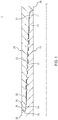
- FIG. 1 is a vertical cross-sectional view of a threaded connection 1 for steel pipe according to an embodiment.
- the threaded connection 1 is an integral-type threaded connection and is composed of a pin 10 and a box 20. Alternatively, the construction of the threaded connection 1 may be applied to a coupling-type threaded connection.
- the threaded connection 1 is a slim-type one where the difference between the outer diameter of the box 20 and the outer diameter of the steel-pipe body 30 is small.
- the outer diameter of the box 20 is smaller than 108 % of the outer diameter of the steel-pipe body 30.
- the outer diameter of the box 20 is 100 % of the outer diameter of the steel-pipe body 30 or larger.
- the steel-pipe body 30 means portions of the steel pipes connected by the threaded connection 1 that are other than the pin 10 and box 20.
- the pin 10 includes, beginning with its tip toward the body 30 of the steel pipe, a pin lip 12 including a first seal surface 11, a male thread 13, and a second seal surface 14.
- the pin 10 further includes a shoulder surface 15 on its end close to the steel-pipe body 30.
- the inner diameter of the pin 10 is larger than the drift diameter specified by the American Petroleum Institute (API) standards.
- API American Petroleum Institute
- the direction toward the tip of the pin 10 may be hereinafter referred to as inward with respect to the pipe-axis direction, and the direction toward the end of the pin 10 close to the steel-pipe body 30 as outward with respect to the pipe-axis direction.
- the first seal surface 11 is provided on the outer periphery of the pin lip 12 extending from the male thread 13 toward the tip.
- the second seal surface 14 is provided on the outer periphery of the pin 10 and located closer to the steel-pipe body 30 than the male thread 13 is. Thus, on the outer periphery of the pin 10, the male thread 13 is located between the first and second seal surfaces 11 and 14.
- the first and second seal surfaces 11 and 14 are tapered. More exactly, each of the first and second seal surfaces 11 and 14 has the shape of a face corresponding to the periphery of a truncated cone decreasing in diameter toward the tip of the pin 10, or the shape of a face corresponding to the periphery of such a truncated cone and the periphery of a solid of revolution obtained by rotating a curve such as an arc about the pipe axis CL, or the shape obtained by combining them.
- the shoulder surface 15 is an annular surface almost perpendicular to the pipe axis CL.
- the shoulder surface 15 slightly inclines toward the direction of advancement of screw-in of the pin 10 relative to a plane perpendicular to the pipe axis CL, i.e. slightly inclines toward the tip of the pin 10 at its outer periphery.
- the box 20 includes, arranged outwardly with respect to the pipe-axis direction, a first seal surface 21, a female thread 23, and a box lip 22 including a second seal surface 24.
- the box 20 further includes a shoulder surface 25 on its outward end.
- the first seal surface 21, female thread 23, second seal surface 24 and shoulder surface 25 of the box 20 correspond to the first seal surface 11, male thread 13, second seal surface 14 and shoulder surface 15 of the pin 10.
- the male thread 13 of the pin 10 and the female thread 23 of the box 20 are constituted by single-stage tapered threads capable of engaging each other.
- the thread shape of the male and female threads 13 and 23 is dove-tailed.
- the thread width of the male and female threads 13 and 23 changes along the direction of advancement of screw-in of the pin 10. More specifically, the width of the ridges of the male thread 13 decreases as it goes in the direction of advancement of the right-hand screw along the helix of the thread (lead), and the thread groove width of the opposite female thread 23 also decreases as it goes in the direction of advancement of the right-hand screw along the helix of the thread.
- the male and female threads 13 and 23 allow each other to be screwed in.
- the first seal surfaces 11 and 21 and the second seal surfaces 14 and 24 contact each other as the pin 10 is screwed in, and, when assembled, they fit together in close contact and are in a state of interference fit.
- the first seal surfaces 11 and 21 form a first seal portion (inner seal portion) in metal-to-metal contact.
- the second seal surfaces 14 and 24 form a second seal portion (outer seal portion) in metal-to-metal contact.
- the shoulder surfaces 15 and 25 contact each other and are pressed against each other, thereby serving as a stop that limits screw-in of the pin 10. Further, when assembled, the shoulder surfaces 15 and 25 serve to provide the male thread 13 of the pin 10 with a load in the direction (rearward) opposite to the direction (forward) of advancement of screw-in, i.e. so-called thread-tightening axial forces.
- the shoulder surfaces 15 and 25 form a shoulder portion by this mutual press-contact.
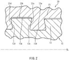
- FIG. 2 is an enlarged vertical cross-sectional view of the threads of the threaded connection 1.
- the thread assembly includes the male thread 13 of the pin 10 and the female thread 23 of the box 20.
- the threads are preferably single-start or double-start threads.
- the male thread 13 of the pin 10 includes a plurality of thread crest surfaces 13a, thread root surfaces 13b, stabbing flank surfaces 13c going first during screw-in (hereinafter also referred to as “stabbing surfaces”) and load flank surfaces 13d opposite to the stabbing surfaces 13c (hereinafter also referred to as "load surfaces”).
- the female thread 23 of the box 20 includes a plurality of thread crest surfaces 23a, thread root surfaces 23b, stabbing surfaces 23c and load surfaces 23d.
- Each thread crest surface 23a of the female thread 23 faces the corresponding thread root surface 13b of the male thread 13.
- Each thread root surface 23b of the female thread 23 faces the corresponding thread crest surface 13a of the male thread 13.
- Each stabbing surface 23c of the female thread 23 faces the corresponding stabbing surface 13c of the male thread 13.
- Each load surface 23d of the female thread 23 faces the corresponding load surface 13d of the male thread 13.
- flank angles of the load surfaces 13d and 23d and stabbing surfaces 13c and 23c of the male thread 13 and female thread 23 are negative angles less than 0°.
- flank angle is the angle formed by a plane perpendicular to the pipe axis CL and a flank surface.
- the flank angles of the load surfaces 13d and 23d are positive if clockwise, while the flank angles of the stabbing surfaces 13c and 23c are positive if counterclockwise.
- the load surfaces 13d and 23d of the male and female threads 13 and 23 contact each other and the stabbing surfaces 13c and 23c contact each other, while the thread root surface 13b of the male thread 13 and the thread crest surface 23a of the female thread 23 contact each other.
- a clearance is formed between the thread crest surface 13a of the male thread 13 and the thread root surface 23b of the female thread 23.
- the thread crest surface 13a of the male thread 13 and the thread root surface 23b of the female thread 23 may contact each other while a clearance may be formed between the thread root surface 13b of the male thread 13 and the thread crest surface 23a of the female thread 23.
- a clearance may be formed between the stabbing surfaces 13c and 23c of the male thread 13 and female thread 23.
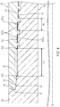
- FIG. 3 is an enlarged vertical cross-sectional view of the end of the threaded connection 1 close to the pin lip 12 (the inward end with respect to the pipe-axis direction).
- the male thread 13 includes, near its end close to the pin lip 12, a plurality of thread root surfaces 131b extending parallel to the pipe axis CL and having the same diameter.
- the two or more of the thread root surfaces 131b of the male thread 13 that are located most inward with respect to the pipe-axis direction substantially have the shape of the side of a cylinder. That is, the thread root surfaces 131b are made of the side of a cylinder having an axial center consistent with the pipe axis CL.
- the depth of the thread grooves near the inward portion of the male thread 13 gradually decreases toward the pin lip 12 in the pipe-axis direction.
- Those ones of the thread root surfaces of the male thread 13 that are other than the thread root surfaces 131b are shaped along the periphery of a truncated cone decreasing in diameter toward the pin lip 12.
- the thread crest surfaces 231a of the female thread 23 that correspond to the thread root surfaces 131b of the male thread 13 extend parallel to the pipe axis CL and have the same diameter. That is, in the female thread 23, the two or more thread crest surfaces 231a located most inward with respect to the pipe-axis direction extend parallel to the pipe axis CL and have the same diameter.
- Each thread crest surface 231a is coaxial with the corresponding thread root surface 131b of the male thread 13, and has the shape of the side of a cylinder with a slightly larger diameter than this thread root surface 131b.
- a clearance C1 is formed between each thread crest surface 231a and the corresponding thread root surface 131b of the male thread 13.
- Those ones of the thread crest surfaces of the male thread 23 that are other than the thread crests 231a are shaped along the periphery of a truncated cone decreasing in diameter as it goes inward with respect to the pipe-axis direction.
- the clearance C1 is created by the difference between the diameter of the side of the cylinder representing the thread crest surfaces 231a of the female thread 23 and the diameter of the side of the cylinder representing the thread root surfaces 131b of the male thread 13.
- the average of C1 is larger than 0 ⁇ m and not larger than 900 ⁇ m, and more preferably not larger than 500 ⁇ m. Average is used herein because an actual product has elliptical errors and C1 is rarely uniform over the entire periphery. Thus, in some cases, C1 may be zero in some portions of the circumference, and portions may exist where the maximum clearance is over 900 ⁇ m.
- the first seal surface 11 of the pin lip 12 is in contact with the first seal surface 21 of the box 20 when assembled. Those portions of the outer periphery of the pin lip 12 that are other than the first seal surface 11 are not in contact with the box 20 when assembled.
- the distance between the male thread 13 and first seal portion as measured in the pipe-axis direction, L1, is preferably 1.5 times the thread pitch P1 or greater, for example.
- the distance L1 is the length beginning at the outward end E11 of the first seal surface 11 in contact with the first seal surface 21 of the box 20 and ending with the inward end E12 of the male thread 13 as measured in the pipe-axis direction.
- Thread pitch P1 means the length between the load surfaces of adjacent thread ridges of the male thread 13 as measured in the pipe-axis direction (in the specification, this definition also applies to the thread pitch for a double-start thread).
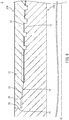
- FIG. 4 is an enlarged vertical cross section of the end of the threaded connection 1 close to the box lip 22 (i.e. outward end in the pipe-axis direction).
- the female thread 23 includes, near its end close to the box lip end 22, a plurality of thread root surfaces 231b extending parallel to the pipe axis CL and having the same diameter.
- the two or more thread rood surfaces 231b of the female thread 23 that are located most outward in the pipe-axis direction substantially have the shape of the side of a cylinder. That is, the thread root surfaces 231b are constituted by the side of the cylinder having an axis consistent with the pipe axis CL.
- the depth of the thread grooves near the outward end of the female thread 23 gradually decreases toward the box lip 22 along the pipe-axis direction.
- Those ones of the thread root surfaces of the female thread 23 that are other than the thread root surfaces 231b are shaped along the periphery of a truncated cone decreasing in diameter as it goes away from the box lip 22.
- the thread crest surfaces 131a of the male thread 13 that correspond to the thread root surfaces 231b of the female thread 23 extend parallel to the pipe axis CL and have the same diameter. That is, the two or more thread crest surfaces 131a of the male thread 13 that are located most outward as determined along the pipe-axis direction extend parallel to the pipe axis CL and have the same diameter.
- the thread crest surfaces 131a are each coaxial with the corresponding thread root surface 231b of the female thread 23 and have the shape of the side of a cylinder having a slightly smaller diameter than the thread root surfaces 231b.
- a clearance C2 is formed between each thread crest surface 131a and the corresponding thread root surface 231b of the female thread 23.
- Those ones of the thread crest surfaces of the male thread 13 that are other than the thread crest surfaces 131a are shaped along the periphery of a truncated cone decreasing in diameter as it goes inward as determined along the pipe-axis direction.
- the clearance C2 is created by the difference between the diameter of the side of the cylinder representing the thread crest surfaces 131a of the male thread 13 and the diameter of the side of the cylinder representing the thread root surfaces 231b of the female thread 23.
- the average of C2 is larger than 0 ⁇ m and not larger than 900 ⁇ m and more preferably not larger than 500 ⁇ m. Average is used herein for the same reasons for C1.
- the second seal surface 24 of the box lip 22 is in contact with the second seal surface 14 of the pin 10 when assembled. Those portions of the inner periphery of the box lip 22 that are other than the second seal surface 24 and shoulder surface 25 do not contact the pin 10 when assembled.
- the distance between the female thread 23 and second seal portion as measured in the pipe-axis direction, L2, is preferably 1.5 times the thread pitch P2 or greater, for example.
- Distance L2 means the length beginning with the inward end E21 of the second seal surface 24 in contact with the second seal portion 14 of the pin 10 and ending with the outward end E22 of the female thread 23 as measured in the pipe-axis direction.
- Thread pitch P2 means the distance between the load surfaces of adjacent thread ridges of the female thread 23 as measured in the pipe-axis direction.
- the male thread 13 includes, near its end close to the pin lip 12, a plurality of thread root surfaces 131b extending parallel to the pipe axis CL and having the same diameter. This increases the wall thickness of the pin lip 12 compared with implementations where all the thread root surfaces of the male thread 13 are arranged along the taper face decreasing in diameter as it goes toward the pin lip 12.
- the thread root surfaces of the male thread 13 are arranged along a taper face, a space must be provided in the outer periphery of the pin lip 12, as indicated by broken lines in FIG. 3 , to allow a tool that moves while inclined relative to the pipe axis CL to escape after the male thread 13 is formed.
- the thread root surfaces 131b near the end of the male thread 13 close to the pin lip 12 extend parallel to the pipe axis CL and have the same diameter, as in the present embodiment, the tool near the end of the thread close to the pin lip 12 moves parallel to the pipe axis CL; as such, no space needs to be provided in the pin lip 12 for allowing the tool to escape.
- the present embodiment prevents the wall thickness of the pin lip 12 including the first seal surface 11 from being reduced, thereby increasing the stiffness of the pin lip 12. This will improve sealing performance against the internal pressure.
- the female thread 23 includes, near its end close to the box lip 22, a plurality of thread root surfaces 231b extending parallel to the pipe axis CL and having the same diameter. This increases the wall thickness of the box lip 22 compared with implementations where all the thread root surfaces of the female thread 23 are arranged along a taper face increasing in diameter toward the box lip 22.
- the thread root surfaces of the female thread 23 are arranged along the taper face, a space must be provided in the inner periphery of the box lip 22, as indicated by broken lines in FIG. 4 , to allow a tool that moves while inclined relative to the pipe axis CL to escape after the female thread 23 is formed.
- the thread root surfaces 231b near the end of the female thread 23 close to the box lip 22 extend parallel to the pipe axis CL and have the same diameter, as in the present embodiment, the tool near the end of the thread close to the box lip 22 moves parallel to the pipe axis CL; as such, no space needs to be provided on the inner periphery of the box lip 22 for allowing the tool to escape.
- the present embodiment prevents the wall thickness of the box lip 22 including the second seal surface 24 from being reduced, thereby increasing the stiffness of the box lip 22. This will improve sealing performance against the external pressure.
- each of the male and female threads 13 and 23 is constituted by a single-stage tapered thread.
- the threaded connection 1 has larger wall thicknesses that can be used for the thread assembly, thereby ensuring sufficient perfect thread portions. This will minimize the decrease in the tensile strength of the thread joint, ensuring a sufficient joint strength.
- the present embodiment ensures sufficient wall thicknesses of the pin lip 12 on which the inner seal is provided and the box lip 22 on which the outer seal is provided, thereby improving sealing performance against both the internal and external pressures. Further, joint strength, particularly tensile strength is not decreased in order to improve sealing performance.
- the thread root surfaces 131b of the male thread 13 provided near the end thereof close to the pin lip 12 have the shape of the side of a cylinder with a slightly smaller diameter than the corresponding thread crest surfaces 231a of the female thread 23.
- the clearance C1 between a thread root surface 131b of the male thread 13 and the corresponding thread crest surface 231a of the female thread 23 is relatively small.
- the thread root surfaces 231b of the female thread 23 provided near the end thereof close to the box lip 22 have the shape of the side of a cylinder with a slightly larger diameter than the corresponding thread crest surfaces 131a of the male thread 13.
- the clearance C2 between a thread root surface 231b of the female thread 23 and the corresponding thread crest surface 131a of the male thread 13 is relatively small. That is, according to the present embodiment, the clearances between thread crest surfaces and the corresponding thread root surfaces near the inner and outward ends of the thread assembly constituted by tapered threads are smaller than those of conventional arrangements. According to the present inventors, adopting this arrangement will increase the wall thicknesses that can be used for the pin lip 12 and box lip 22. This will further improve sealing performance against the internal and external pressures.
- a shoulder surface 15 is provided on the end of the pin 10 close to the steel-pipe body 30.
- the box 20 includes a shoulder surface 25 corresponding to the shoulder surface 15 of the pin 10. Since the shoulder surfaces 15 and 25 are in contact with each other when assembled, they can serve as a stop for limiting screw-in of the pin 10 into the box 20. Further, the shoulder surfaces 15 and 25 are capable of generating a thread-tightening axial force inside the connection.
- the thread assembly composed of the male and female threads 13 and 23 has dove-tailed shape and has varying thread widths.
- the load surfaces are in contact with each other and the thread crest surfaces and the thread root surfaces are in close contact, achieving good sealing performance. If the stabbing surfaces are also in contact with each other when assembling of the pin 10 and box 20 is completed, the entire threads firmly fit together, further improving sealing performance.
- Each of the first and second seal portions has such a fit margin (or amount of interference) that the first seal surfaces 11 and 21 and the second seal surfaces 14 and 24 are in close contact with a sufficient contact force along the entire circumference when assembled to exhibit a sufficient sealing performance. Accordingly, if the distance between the first and/or second seal portions and the thread portion as measured in the pipe-axis direction is too small, the amount of interference of the first and/or second seal portions may move the female thread 23 out of engagement with the male thread 13, resulting in a decrease in the strength of the thread joint near the ends of the threads.
- the present embodiment provides a distance L1 between the thread portion and first seal portion as measured in the pipe-axis direction to prevent the contact between the first seal surfaces 11 and 21 and the contact between the male and female threads 13 and 23 from adversely affecting each other. Further, the present invention provides a distance L2 between the thread portion and second seal portion as measured in the pipe-axis direction to prevent the contact between the second seal surfaces 14 and 24 and the contact between the male and female threads 13 and 23 from adversely affecting each other.
- the distances L1 and L2 are 1.5 times the thread pitches P1 and P2, respectively, or larger. This will prevent the strength of the thread joint from being decreased by the amounts of interference of the first and/or second seal portions.
- a clearance C1 is present between a thread root surface 131b of the male thread 13 and the corresponding thread crest surface 231a of the female thread 23.
- a clearance C2 is created between a thread crest surface 131a of the male thread 13 and the corresponding thread root surface 231b of the female thread 23.
- the clearances C1 and C2 are preferably established according to the unevenness (or manufacturing tolerance) in the circularity (or ovality) of the inward and outward ends of the threaded portion as determined along the pipe-axis direction.
- the circularity greatly varies depending on, for example, the outer diameter of the steel pipe, wall thickness size, material, manufacturing method and other factors.
- the circularity is generally not lower than 5 % and not higher than 50 % of the height (or radial dimensions) of the load surface of the lower one of a perfect ridge of the male thread 13 and a perfect ridge of the female thread 23, and more preferably not lower than 10 % and not higher than 30 %.
- the thread ridge height and thread taper of the thread portion are not limited to any particular values.
- the thread ridge height and thread taper can be adjusted according to the outer diameter and wall thickness size of the steel pipe, for example. If the connection is used for steel pipes for oil wells, the thread ridge height may be generally in the range of 0.8 mm to 3 mm. If the connection is used for steel pipes for oil wells, the thread taper may be generally in the range of 1/21 to 1/4.
- each of the flank angles of the load surface and stabbing surface may be, for practical reasons, not lower than -31° and lower than 0°. From the viewpoint of manufacturability, each of the flank angles of the load surface and stabbing surface may be, more preferably, in the range of -16° to -2°. The flank angle of the load surface and the flank angle of the stabbing surface do not have be to equal.
- the present embodiment is particularly used for flush-type, semi-flush-type and slim-type threaded connections for steel pipe, in which the difference between the outer diameter of the box 20 and the outer diameter of the steel-pipe body 30 is small.
- the outer diameter of the box 20 is not larger than 108 % of the outer diameter of the steel-pipe body 30.
- the outer diameter of the box 20 is not larger than 104 % of the outer diameter of the steel-pipe body 30.
- the lower limit for the inner diameter of the threaded connection 1 i.e. inner diameter of the pin 10) may be, for example, the drift diameter of SPEC 5CT in accordance with the API standards.
- first seal surfaces 11 and 21 and the second seal surfaces 14 and 24 are not limited to any particular values.
- the profile of each of the first seal surfaces 11 and 21 and second seal surfaces 14 and 24 may be constructed by a straight line, an arc, a partial ellipse or a smooth convex line, or a combination thereof.
- the distance between the thread portion and first seal portion as measured in the pipe-axis direction, L1, and the distance between the thread portion and second seal portion as measured in the pipe-axis direction, L2 are preferably 1.5 times of the thread pitches P1 and P2, respectively, or larger, although they may vary depending on the outer diameter or wall thickness size of the threaded connection 1, for example. From the viewpoints of manufacturing costs and handleability, the distances L1 and L2 may be not larger than 5 times the thread pitches P1 and P2, respectively.
- the circumferential tensile yield strength of the ends of the box 20 may be increased by cold expansion forming, for example.
- the circumferential tensile yield strength at the second seal surface 24 of the box 20 is preferably increased by at least 5 % relative to the tensile yield strength of the steel-pipe body 30, and more preferably increased by 10 % or higher.
- the pin or box may include a nose.
- FIG. 5 is an enlarged vertical cross-sectional view of the inward end, as determined along the pipe-axis direction, of the threaded connection 2 for steel pipe according to a variation of the above-described embodiment.
- the threaded connection 2 for steel pipe is different from the threaded connection 1 for steel pipe according to the above-described embodiment in that the pin 10A includes a nose 16.
- the nose 16 is located on the inward-most portion of the pin lip 12 as determined along the pipe-axis direction.
- the nose 16 is located between the tip surface of the pin 10A and the first seal surface 11 of the pin 10A.
- a shoulder surface similar to that of the above-described embodiment may be provided on the outward ends of the pin 10A and box 20A as determined along the pipe-axis direction; alternatively, no shoulder surface may be provided.
- the outer periphery of the nose 16 When assembled, the outer periphery of the nose 16 is not in contact with the box 20A. Providing the nose 16 on the pin 10A increases the stiffness of the pin lip 12. This will further improve sealing performance against the internal pressure.
- FIG. 6 is an enlarged vertical cross-sectional view of the outward end, as determined along the pipe-axis direction, of the threaded connection 3 for steel pipe according to a variation of the above-described embodiment.
- the threaded connection 3 for steel pipe is different from the threaded connection 1 for steel pipe according to the above-described embodiment in that the box 20B includes a nose 26.
- the nose 26 is located on the outward-most portion of the box lip 22 as determined along the pipe-axis direction.
- the nose 26 is located between the second seal surface 24 of the box 20B and the shoulder surface 25 of the box 20B. That is, the shoulder surface 25 is provided on the tip of the nose 26.
- the shoulder surface 25 of the box 20B is in contact with the shoulder surface 15 of the pin 10B, similar to the shoulder surface of the above-described embodiment, but the inner periphery of the nose 26 is not in contact with the pin 10B. Providing this nose 26 on the box 20B increases the stiffness of the box lip 22. This will further improve sealing performance against the external pressure.
- the circumferential tensile yield strength of the box lip 22 including the nose 26 and second seal surface 24 of the box 20B may be increased by cold expansion forming, for example.
- the circumferential tensile yield strength at the nose 26 and second seal surface 24 is preferably increased by at least 5 % relative to the tensile yield strength of the steel-pipe body, and more preferably increased by 10 % or more.
- FIGS. 5 and 6 show implementations where a nose is provided on the pin or box. However, noses may be provided on both the pin and box.
- a shoulder surface 17 may be provided on the tip of the pin 10, as shown in FIG. 7 .
- the box 20C includes a shoulder surface 27 corresponding to the shoulder surface 17 of the pin 10C. When assembled, the shoulder surface 17 of the pin 10 is in contact with the shoulder surface 27 of the box 20.
- a shoulder surface similar to that of the above-described embodiment may be provided on the end surface of the pin 10C close to the steel-pipe body, or no such shoulder surface may be provided.
- a pin shoulder surface may be provided on one or both of the tip of the pin and the end surface thereof close to the steel-pipe body.
- the box includes a shoulder surface or shoulder surfaces corresponding to the shoulder surface(s) of the pin.
- the thread assembly is composed of dove-tailed threads; however, the configuration of the thread assembly is not limited thereto.
- the male thread 13A (13) and female thread 23A (23) may be trapezoidal threads.
- the male thread 13A (13) includes, near the inward end as determined along the pipe-axis direction, a plurality of thread root surfaces extending parallel to the pipe axis CL and having the same diameter
- the female thread 23A (23) includes, near the outward end as determined along the pipe-axis direction, a plurality of thread root surfaces extending parallel to the pipe axis CL and having the same diameter.
- the model of a threaded connection for steel pipe used in the elastic-plastic finite element analysis included an inner seal portion composed of first seal surfaces 11 and 21, an outer seal portion composed of second seal surfaces 14 and 24, a shoulder portion composed of shoulder surfaces 15 and 25, and a nose 26 provided between the outer seal portion and shoulder portion.
- the models of the inventive example and comparative example described below have the same basic construction.
- a model was created by applying the techniques of the present disclosure to a threaded connection having this basic construction to serve as the inventive example. That is, as shown in FIG. 10 , near the outward end of the thread assembly as determined along the pipe-axis direction, the thread root surfaces of the female thread 23 and the corresponding thread crest surfaces of the male thread 13 extended parallel to the pipe axis CL. Although not shown, near the inward end of the thread assembly as determined along the pipe-axis direction, the thread root surfaces of the male thread 13 and the corresponding thread crest surfaces of the female thread 23 extended parallel to the pipe axis CL.
- the wall thickness of the pin lip was 6.11 mm and the wall thickness of the box lip was 7.19 mm.
- the distance between the male thread 13 and the inner seal portion as measured in the pipe-axis direction was two times the thread pitch.
- the distance between the female thread 23 and outer seal portion as measured in the pipe-axis direction was also two times the thread pitch.
- a model was created having the above-described basic construction to which the techniques of the present disclosure was not applied to illustrate a conventional technique for comparison (comparative example).
- the construction of the outward end of the model of the comparative example as determined along the pipe-axis direction is indicated by broken lines in FIG. 10 .
- the wall thickness of the pin lip was 4.98 mm and the wall thickness of the box lip was 5.98 mm.
- test conditions common to the inventive and comparative examples are as follows:
- the contact forces on the inner and outer seal surfaces of the inventive example are much higher than the contact forces on the inner and outer seal surfaces of the comparative example.
Landscapes
- Engineering & Computer Science (AREA)
- General Engineering & Computer Science (AREA)
- Mechanical Engineering (AREA)
- Mining & Mineral Resources (AREA)
- Life Sciences & Earth Sciences (AREA)
- Geology (AREA)
- Fluid Mechanics (AREA)
- Environmental & Geological Engineering (AREA)
- Physics & Mathematics (AREA)
- General Life Sciences & Earth Sciences (AREA)
- Geochemistry & Mineralogy (AREA)
- Non-Disconnectible Joints And Screw-Threaded Joints (AREA)
- Mutual Connection Of Rods And Tubes (AREA)
Claims (6)
- Gewindeverbindung für (1) ein Stahlrohr mit einem Rohrstift (10) und einem Rohrgehäuse (20); wobei der Rohrstift (10) und das Gehäuse (20) zusammengebaut werden, wenn der Stift (10) in das Gehäuse (20) eingeschraubt wird, wobei: das Gehäuse einen Außendurchmesser hat, der kleiner als 108% eines Außendurchmessers eines Körpers des Stahlrohrs ist,
der Stift (10) beginnend mit seiner Spitze zum Körper (30) des Stahlrohrs hin eine Stiftlippe (12) mit einer ersten Dichtfläche (11), einem Außengewinde (13) und einer zweiten Dichtfläche (14) umfasst,
das Gehäuse (20) Folgendes umfasst: eine erste Dichtfläche (21), die der ersten Dichtfläche (11) des Stifts (10) entspricht, ein Innengewinde (23), das dem Außengewinde (13) entspricht, und eine Gehäuselippe (22) mit einer zweiten Dichtfläche (24), die der zweiten Dichtfläche (14) des Stifts (10) entspricht;
im zusammengebauten Zustand die ersten Dichtflächen (11, 21) miteinander in Kontakt stehen und die zweiten Dichtflächen (14, 24) miteinander in Kontakt stehen.
dadurch gekennzeichnet, dass:ein Abschnitt des Außengewindes (13), der sich in der Nähe eines Endes davon nahe der Stiftlippe (12) befindet, mehrere Gewindewurzelflächen (131b) umfasst, die sich parallel zu einer Rohrachse (CL) erstrecken und den gleichen Durchmesser aufweisen,ein Abschnitt des Innengewindes (23), der sich in der Nähe eines Endes davon nahe der Gehäuselippe (22) befindet, mehrere Gewindewurzelflächen (231b) umfasst, die sich parallel zur Rohrachse (CL) erstrecken und den gleichen Durchmesser aufweisen, unddass das Außengewinde aus einem einstufigen Kegelgewinde besteht und das Innengewinde aus einem einstufigen Kegelgewinde besteht. - Gewindeverbindung für ein Stahlrohr nach Anspruch 1, wobei:der Stift (10) ferner eine Schulterfläche (15), die an mindestens einer der Spitzen vorgesehen ist, und eine Endfläche nahe dem Körper (30) des Stahlrohrs umfasst,das Gehäuse (20) ferner eine Schulterfläche (25) umfasst, die der Schulterfläche (15) des Stifts (10) entspricht, unddie entsprechenden Schulterflächen (15, 25) beim Zusammenbau in Kontakt stehen.
- Gewindeverbindung (1) für ein Stahlrohr nach Anspruch 1 oder 2, wobei der Stift (10) ferner eine erste Nase (16) umfasst, die zwischen einer Spitzenfläche und der ersten Dichtungsfläche (11) des Stifts (10) angeordnet ist.
- Gewindeverbindung (1) für ein Stahlrohr nach einem der Ansprüche 1 bis 3, wobei das Gehäuse (20) ferner eine zweite Nase (26) umfasst, die zwischen einer Endfläche angeordnet ist, die einer Endfläche (10C) des Stifts (10) nahe dem Stahlrohrkörper (30) und der zweiten Dichtfläche (24) des Gehäuses (20) entspricht.
- Gewindeverbindung (1) für ein Stahlrohr nach einem der Ansprüche 1 bis 4, wobei eine Gewindeanordnung, die das Außengewinde (13) und das Innengewinde (23) umfasst, eine Schwalbenschwanzgewindeform und eine Gewindebreite aufweist, die sich entlang einer Steigung ändert.
- Gewindeverbindung (1) für ein Stahlrohr nach einem der Ansprüche 1 bis 5, wobei eine Gewindeanordnung, die das Außengewinde (13) und das Innengewinde (23) umfasst, eine Einzelstart- oder Doppelstartgewindeform aufweist.
Priority Applications (1)
| Application Number | Priority Date | Filing Date | Title |
|---|---|---|---|
| PL16857345T PL3366968T3 (pl) | 2015-10-21 | 2016-10-13 | Połączenie gwintowe dla rur stalowych |
Applications Claiming Priority (2)
| Application Number | Priority Date | Filing Date | Title |
|---|---|---|---|
| JP2015207145 | 2015-10-21 | ||
| PCT/JP2016/080321 WO2017069030A1 (ja) | 2015-10-21 | 2016-10-13 | 鋼管用ねじ継手 |
Publications (3)
| Publication Number | Publication Date |
|---|---|
| EP3366968A1 EP3366968A1 (de) | 2018-08-29 |
| EP3366968A4 EP3366968A4 (de) | 2019-05-22 |
| EP3366968B1 true EP3366968B1 (de) | 2020-12-02 |
Family
ID=58557296
Family Applications (1)
| Application Number | Title | Priority Date | Filing Date |
|---|---|---|---|
| EP16857345.9A Not-in-force EP3366968B1 (de) | 2015-10-21 | 2016-10-13 | Gewindeanschluss für stahlrohre |
Country Status (13)
| Country | Link |
|---|---|
| US (1) | US10883319B2 (de) |
| EP (1) | EP3366968B1 (de) |
| JP (1) | JP6654643B2 (de) |
| CN (1) | CN108138994B (de) |
| AU (1) | AU2016340415B2 (de) |
| BR (1) | BR112018003384B1 (de) |
| CA (1) | CA3001670C (de) |
| EA (1) | EA035105B1 (de) |
| MX (1) | MX2018004757A (de) |
| MY (1) | MY182111A (de) |
| PL (1) | PL3366968T3 (de) |
| UA (1) | UA122422C2 (de) |
| WO (1) | WO2017069030A1 (de) |
Families Citing this family (14)
| Publication number | Priority date | Publication date | Assignee | Title |
|---|---|---|---|---|
| JP7253649B2 (ja) * | 2017-10-12 | 2023-04-06 | 三菱鉛筆株式会社 | 筆記具 |
| EP3473798B2 (de) * | 2017-10-20 | 2025-06-18 | Vallourec Oil And Gas France | Gewindeverbindung, teilweise in einem selbsthemmenden eingriff |
| EA038944B1 (ru) * | 2017-11-09 | 2021-11-12 | Ниппон Стил Корпорейшн | Резьбовое соединение для стальной трубы |
| RU2742962C1 (ru) * | 2018-03-05 | 2021-02-12 | ДжФЕ СТИЛ КОРПОРЕЙШН | Резьбовое соединение труб для нефтяных скважин |
| CA3114740C (en) * | 2018-10-02 | 2023-01-03 | Nippon Steel Corporation | Threaded connection for steel pipe |
| WO2020075366A1 (ja) * | 2018-10-11 | 2020-04-16 | 日本製鉄株式会社 | 鋼管用ねじ継手 |
| UA128488C2 (uk) * | 2019-03-27 | 2024-07-24 | Ніппон Стіл Корпорейшн | Нарізне з'єднання для сталевої труби |
| CA3144973A1 (en) * | 2019-07-12 | 2021-01-21 | Hydril Company | Threaded connection for exploration and production of a hydrocarbon well |
| CN110608321B (zh) * | 2019-08-30 | 2024-07-23 | 江苏璞腾油气装备有限公司 | 一种双线海洋隔水管接头 |
| CN113739674A (zh) * | 2020-05-29 | 2021-12-03 | 宝山钢铁股份有限公司 | 一种用于螺纹接头上螺纹齿宽的检验量规及其检验方法 |
| CN114322716B (zh) * | 2020-09-29 | 2023-11-14 | 宝山钢铁股份有限公司 | 检测螺纹油套管上密封面轮廓误差的校对仪及其校对方法 |
| US12287048B2 (en) * | 2022-11-01 | 2025-04-29 | Saudi Arabian Oil Company | Pipe connection systems in oil and gas applications |
| JPWO2024106291A1 (de) * | 2022-11-15 | 2024-05-23 | ||
| AU2024272329A1 (en) * | 2023-05-18 | 2025-11-20 | National Oilwell Varco, L.P. | Threaded tubular members employing metal-to-metal seals |
Family Cites Families (35)
| Publication number | Priority date | Publication date | Assignee | Title |
|---|---|---|---|---|
| US1973848A (en) * | 1932-05-26 | 1934-09-18 | Peter J Duffy | Flush joint drill stem |
| US3508771A (en) | 1964-09-04 | 1970-04-28 | Vallourec | Joints,particularly for interconnecting pipe sections employed in oil well operations |
| US3572777A (en) | 1969-05-05 | 1971-03-30 | Armco Steel Corp | Multiple seal, double shoulder joint for tubular products |
| US3994516A (en) * | 1975-03-05 | 1976-11-30 | Otis Engineering Corporation | Telescoping pipe coupling with improved pressure seal connection threads |
| GB1583038A (en) | 1976-04-22 | 1981-01-21 | Hydril Co | Screw thread connection for pin and box pipe joints |
| FR2359353A1 (fr) | 1976-07-23 | 1978-02-17 | Vallourec | Joint pour tubes, notamment pour tubes petroliers |
| US4616537A (en) * | 1983-04-04 | 1986-10-14 | Awb, Inc. | Pipe connection |
| US4568113A (en) * | 1983-04-04 | 1986-02-04 | Awb, Inc. | Pipe connection |
| US4917409A (en) * | 1983-04-29 | 1990-04-17 | Hydril Company | Tubular connection |
| GB8617827D0 (en) * | 1986-07-22 | 1986-08-28 | British Steel Corp | Joints for tubular members |
| JPH0280886A (ja) * | 1988-09-14 | 1990-03-20 | Nippon Steel Corp | シール面圧保持機能の優れた油井管用ネジ継手 |
| US5462315A (en) | 1992-03-09 | 1995-10-31 | Marubeni Tubulars, Inc. | Stabilized center-shoulder-sealed tubular connection |
| US5687999A (en) * | 1995-10-03 | 1997-11-18 | Vallourec Oil & Gas | Threaded joint for tubes |
| US6485063B1 (en) * | 1996-05-15 | 2002-11-26 | Huey P. Olivier | Connection |
| JPH1089554A (ja) * | 1996-09-17 | 1998-04-10 | Sumitomo Metal Ind Ltd | 異強度部を有するスリム型油井管用ねじ継手およびその製造方法 |
| JP3739543B2 (ja) | 1996-10-02 | 2006-01-25 | 三井化学株式会社 | ヒドロキシ安息香酸類の製造方法 |
| JPH10280886A (ja) | 1997-04-09 | 1998-10-20 | Housing Tamura:Kk | セグメントのジョイント構造 |
| JPH113728A (ja) * | 1997-04-17 | 1999-01-06 | Fuji Photo Film Co Ltd | 非水電解液二次電池 |
| JPH1113728A (ja) * | 1997-06-27 | 1999-01-22 | Nippon Steel Corp | 地すべり抑止杭用ねじ継手 |
| WO1999008034A1 (en) | 1997-08-11 | 1999-02-18 | Marubeni Tubulars, Inc. | Tubular connection |
| US6158785A (en) | 1998-08-06 | 2000-12-12 | Hydril Company | Multi-start wedge thread for tubular connection |
| UA66876C2 (uk) * | 1998-09-07 | 2004-06-15 | Валлурек Маннесманн Ойл Енд Гес Франс | Різьбове з'єднання двох металевих труб з пазом, виконаним в різьбі |
| GB2358228B (en) | 2000-01-13 | 2002-11-06 | Ian Harold Hignett | Improvements to pipe joints |
| US20050093250A1 (en) | 2003-11-05 | 2005-05-05 | Santi Nestor J. | High-strength sealed connection for expandable tubulars |
| JP2007205361A (ja) | 2004-08-27 | 2007-08-16 | Sumitomo Metal Ind Ltd | 鋼管用ねじ継手 |
| EP2002165B1 (de) * | 2006-03-31 | 2017-09-06 | Nippon Steel & Sumitomo Metal Corporation | Rohrförmige gewindeverbindung |
| JP5100755B2 (ja) * | 2007-10-03 | 2012-12-19 | 住友金属工業株式会社 | 鋼管用ねじ継手 |
| CN201202903Y (zh) * | 2008-04-22 | 2009-03-04 | 西南石油大学 | 高膨胀率补贴管接头密封结构 |
| FR2945850B1 (fr) * | 2009-05-20 | 2011-06-24 | Vallourec Mannesmann Oil & Gas | Ensemble pour la fabrication d'un joint filete pour le forage et l'exploitation des puits d'hydrocarbures et joint filete resultant |
| US8535762B2 (en) * | 2009-10-09 | 2013-09-17 | Tenaris Connections Limited | Tubular joint having wedge threads with surface coating |
| JP5779990B2 (ja) * | 2010-06-30 | 2015-09-16 | Jfeスチール株式会社 | ねじ切削方法 |
| US10215314B2 (en) | 2010-08-23 | 2019-02-26 | Vallourec Oil And Gas France | Tubular threaded connection |
| US9869139B2 (en) * | 2012-11-28 | 2018-01-16 | Ultra Premium Oilfield Services, Ltd. | Tubular connection with helically extending torque shoulder |
| WO2015105054A1 (ja) * | 2014-01-09 | 2015-07-16 | 新日鐵住金株式会社 | 鋼管用ねじ継手 |
| US10281066B2 (en) * | 2014-03-07 | 2019-05-07 | Houston International Specialty, Inc. | Flush threaded connection and method of forming and using the flush threaded connection |
-
2016
- 2016-10-13 CA CA3001670A patent/CA3001670C/en active Active
- 2016-10-13 JP JP2017546515A patent/JP6654643B2/ja not_active Expired - Fee Related
- 2016-10-13 AU AU2016340415A patent/AU2016340415B2/en not_active Ceased
- 2016-10-13 MX MX2018004757A patent/MX2018004757A/es unknown
- 2016-10-13 PL PL16857345T patent/PL3366968T3/pl unknown
- 2016-10-13 WO PCT/JP2016/080321 patent/WO2017069030A1/ja not_active Ceased
- 2016-10-13 CN CN201680059893.4A patent/CN108138994B/zh not_active Expired - Fee Related
- 2016-10-13 EA EA201890784A patent/EA035105B1/ru not_active IP Right Cessation
- 2016-10-13 EP EP16857345.9A patent/EP3366968B1/de not_active Not-in-force
- 2016-10-13 UA UAA201804345A patent/UA122422C2/uk unknown
- 2016-10-13 US US15/768,379 patent/US10883319B2/en not_active Expired - Fee Related
- 2016-10-13 MY MYPI2018700395A patent/MY182111A/en unknown
- 2016-10-13 BR BR112018003384-7A patent/BR112018003384B1/pt not_active IP Right Cessation
Non-Patent Citations (1)
| Title |
|---|
| None * |
Also Published As
| Publication number | Publication date |
|---|---|
| CA3001670C (en) | 2020-04-14 |
| BR112018003384A2 (pt) | 2018-09-25 |
| US10883319B2 (en) | 2021-01-05 |
| EP3366968A1 (de) | 2018-08-29 |
| WO2017069030A1 (ja) | 2017-04-27 |
| AU2016340415B2 (en) | 2018-12-20 |
| CA3001670A1 (en) | 2017-04-27 |
| PL3366968T3 (pl) | 2021-06-14 |
| EP3366968A4 (de) | 2019-05-22 |
| AU2016340415A1 (en) | 2018-02-22 |
| EA201890784A1 (ru) | 2018-09-28 |
| BR112018003384B1 (pt) | 2022-08-30 |
| UA122422C2 (uk) | 2020-11-10 |
| JP6654643B2 (ja) | 2020-02-26 |
| EA035105B1 (ru) | 2020-04-28 |
| MX2018004757A (es) | 2018-06-19 |
| JPWO2017069030A1 (ja) | 2018-05-31 |
| CN108138994B (zh) | 2020-01-24 |
| US20180313168A1 (en) | 2018-11-01 |
| MY182111A (en) | 2021-01-18 |
| CN108138994A (zh) | 2018-06-08 |
Similar Documents
| Publication | Publication Date | Title |
|---|---|---|
| EP3366968B1 (de) | Gewindeanschluss für stahlrohre | |
| EP3093543B2 (de) | Schraubverbindung für stahlrohre | |
| EP3205918B1 (de) | Schraubverbindung für stahlrohre | |
| EP4036449B1 (de) | Schraubverbindung | |
| US20230146768A1 (en) | Threaded connection for steel pipe | |
| AU2023200341B2 (en) | Threaded connection for steel pipe | |
| OA18648A (en) | Threaded fitting for steel pipes. | |
| OA21091A (en) | Screw-threaded joint | |
| OA21386A (en) | Threaded joint for steel pipe. | |
| OA20843A (en) | Threaded Coupling For Steel Pipe |
Legal Events
| Date | Code | Title | Description |
|---|---|---|---|
| STAA | Information on the status of an ep patent application or granted ep patent |
Free format text: STATUS: THE INTERNATIONAL PUBLICATION HAS BEEN MADE |
|
| PUAI | Public reference made under article 153(3) epc to a published international application that has entered the european phase |
Free format text: ORIGINAL CODE: 0009012 |
|
| STAA | Information on the status of an ep patent application or granted ep patent |
Free format text: STATUS: REQUEST FOR EXAMINATION WAS MADE |
|
| 17P | Request for examination filed |
Effective date: 20180116 |
|
| AK | Designated contracting states |
Kind code of ref document: A1 Designated state(s): AL AT BE BG CH CY CZ DE DK EE ES FI FR GB GR HR HU IE IS IT LI LT LU LV MC MK MT NL NO PL PT RO RS SE SI SK SM TR |
|
| AX | Request for extension of the european patent |
Extension state: BA ME |
|
| DAV | Request for validation of the european patent (deleted) | ||
| DAX | Request for extension of the european patent (deleted) | ||
| A4 | Supplementary search report drawn up and despatched |
Effective date: 20190423 |
|
| RIC1 | Information provided on ipc code assigned before grant |
Ipc: F16L 15/04 20060101AFI20190415BHEP Ipc: E21B 17/042 20060101ALI20190415BHEP Ipc: F16L 15/06 20060101ALI20190415BHEP |
|
| RAP1 | Party data changed (applicant data changed or rights of an application transferred) |
Owner name: VALLOUREC OIL AND GAS FRANCE Owner name: NIPPON STEEL CORPORATION |
|
| REG | Reference to a national code |
Ref country code: DE Ref legal event code: R079 Ref document number: 602016049215 Country of ref document: DE Free format text: PREVIOUS MAIN CLASS: F16L0015040000 Ipc: E21B0017042000 |
|
| RIC1 | Information provided on ipc code assigned before grant |
Ipc: E21B 17/042 20060101ALI20200207BHEP Ipc: F16L 15/06 20060101ALI20200207BHEP Ipc: F16L 15/04 20060101AFI20200207BHEP |
|
| GRAP | Despatch of communication of intention to grant a patent |
Free format text: ORIGINAL CODE: EPIDOSNIGR1 |
|
| STAA | Information on the status of an ep patent application or granted ep patent |
Free format text: STATUS: GRANT OF PATENT IS INTENDED |
|
| RIC1 | Information provided on ipc code assigned before grant |
Ipc: F16L 15/00 20060101ALI20200313BHEP Ipc: E21B 17/042 20060101AFI20200313BHEP Ipc: F16L 15/06 20060101ALI20200313BHEP |
|
| INTG | Intention to grant announced |
Effective date: 20200408 |
|
| GRAJ | Information related to disapproval of communication of intention to grant by the applicant or resumption of examination proceedings by the epo deleted |
Free format text: ORIGINAL CODE: EPIDOSDIGR1 |
|
| STAA | Information on the status of an ep patent application or granted ep patent |
Free format text: STATUS: REQUEST FOR EXAMINATION WAS MADE |
|
| GRAP | Despatch of communication of intention to grant a patent |
Free format text: ORIGINAL CODE: EPIDOSNIGR1 |
|
| STAA | Information on the status of an ep patent application or granted ep patent |
Free format text: STATUS: GRANT OF PATENT IS INTENDED |
|
| INTG | Intention to grant announced |
Effective date: 20200709 |
|
| GRAS | Grant fee paid |
Free format text: ORIGINAL CODE: EPIDOSNIGR3 |
|
| GRAA | (expected) grant |
Free format text: ORIGINAL CODE: 0009210 |
|
| STAA | Information on the status of an ep patent application or granted ep patent |
Free format text: STATUS: THE PATENT HAS BEEN GRANTED |
|
| AK | Designated contracting states |
Kind code of ref document: B1 Designated state(s): AL AT BE BG CH CY CZ DE DK EE ES FI FR GB GR HR HU IE IS IT LI LT LU LV MC MK MT NL NO PL PT RO RS SE SI SK SM TR |
|
| REG | Reference to a national code |
Ref country code: GB Ref legal event code: FG4D |
|
| REG | Reference to a national code |
Ref country code: RO Ref legal event code: EPE |
|
| REG | Reference to a national code |
Ref country code: AT Ref legal event code: REF Ref document number: 1341134 Country of ref document: AT Kind code of ref document: T Effective date: 20201215 Ref country code: CH Ref legal event code: EP |
|
| REG | Reference to a national code |
Ref country code: IE Ref legal event code: FG4D |
|
| REG | Reference to a national code |
Ref country code: DE Ref legal event code: R096 Ref document number: 602016049215 Country of ref document: DE |
|
| REG | Reference to a national code |
Ref country code: NL Ref legal event code: FP |
|
| REG | Reference to a national code |
Ref country code: NO Ref legal event code: T2 Effective date: 20201202 |
|
| PG25 | Lapsed in a contracting state [announced via postgrant information from national office to epo] |
Ref country code: RS Free format text: LAPSE BECAUSE OF FAILURE TO SUBMIT A TRANSLATION OF THE DESCRIPTION OR TO PAY THE FEE WITHIN THE PRESCRIBED TIME-LIMIT Effective date: 20201202 Ref country code: GR Free format text: LAPSE BECAUSE OF FAILURE TO SUBMIT A TRANSLATION OF THE DESCRIPTION OR TO PAY THE FEE WITHIN THE PRESCRIBED TIME-LIMIT Effective date: 20210303 Ref country code: FI Free format text: LAPSE BECAUSE OF FAILURE TO SUBMIT A TRANSLATION OF THE DESCRIPTION OR TO PAY THE FEE WITHIN THE PRESCRIBED TIME-LIMIT Effective date: 20201202 |
|
| PG25 | Lapsed in a contracting state [announced via postgrant information from national office to epo] |
Ref country code: LV Free format text: LAPSE BECAUSE OF FAILURE TO SUBMIT A TRANSLATION OF THE DESCRIPTION OR TO PAY THE FEE WITHIN THE PRESCRIBED TIME-LIMIT Effective date: 20201202 Ref country code: BG Free format text: LAPSE BECAUSE OF FAILURE TO SUBMIT A TRANSLATION OF THE DESCRIPTION OR TO PAY THE FEE WITHIN THE PRESCRIBED TIME-LIMIT Effective date: 20210302 Ref country code: SE Free format text: LAPSE BECAUSE OF FAILURE TO SUBMIT A TRANSLATION OF THE DESCRIPTION OR TO PAY THE FEE WITHIN THE PRESCRIBED TIME-LIMIT Effective date: 20201202 |
|
| PG25 | Lapsed in a contracting state [announced via postgrant information from national office to epo] |
Ref country code: HR Free format text: LAPSE BECAUSE OF FAILURE TO SUBMIT A TRANSLATION OF THE DESCRIPTION OR TO PAY THE FEE WITHIN THE PRESCRIBED TIME-LIMIT Effective date: 20201202 |
|
| REG | Reference to a national code |
Ref country code: LT Ref legal event code: MG9D |
|
| PG25 | Lapsed in a contracting state [announced via postgrant information from national office to epo] |
Ref country code: EE Free format text: LAPSE BECAUSE OF FAILURE TO SUBMIT A TRANSLATION OF THE DESCRIPTION OR TO PAY THE FEE WITHIN THE PRESCRIBED TIME-LIMIT Effective date: 20201202 Ref country code: SM Free format text: LAPSE BECAUSE OF FAILURE TO SUBMIT A TRANSLATION OF THE DESCRIPTION OR TO PAY THE FEE WITHIN THE PRESCRIBED TIME-LIMIT Effective date: 20201202 Ref country code: LT Free format text: LAPSE BECAUSE OF FAILURE TO SUBMIT A TRANSLATION OF THE DESCRIPTION OR TO PAY THE FEE WITHIN THE PRESCRIBED TIME-LIMIT Effective date: 20201202 Ref country code: PT Free format text: LAPSE BECAUSE OF FAILURE TO SUBMIT A TRANSLATION OF THE DESCRIPTION OR TO PAY THE FEE WITHIN THE PRESCRIBED TIME-LIMIT Effective date: 20210405 Ref country code: SK Free format text: LAPSE BECAUSE OF FAILURE TO SUBMIT A TRANSLATION OF THE DESCRIPTION OR TO PAY THE FEE WITHIN THE PRESCRIBED TIME-LIMIT Effective date: 20201202 |
|
| REG | Reference to a national code |
Ref country code: DE Ref legal event code: R097 Ref document number: 602016049215 Country of ref document: DE |
|
| PG25 | Lapsed in a contracting state [announced via postgrant information from national office to epo] |
Ref country code: IS Free format text: LAPSE BECAUSE OF FAILURE TO SUBMIT A TRANSLATION OF THE DESCRIPTION OR TO PAY THE FEE WITHIN THE PRESCRIBED TIME-LIMIT Effective date: 20210402 |
|
| PLBE | No opposition filed within time limit |
Free format text: ORIGINAL CODE: 0009261 |
|
| STAA | Information on the status of an ep patent application or granted ep patent |
Free format text: STATUS: NO OPPOSITION FILED WITHIN TIME LIMIT |
|
| PG25 | Lapsed in a contracting state [announced via postgrant information from national office to epo] |
Ref country code: AL Free format text: LAPSE BECAUSE OF FAILURE TO SUBMIT A TRANSLATION OF THE DESCRIPTION OR TO PAY THE FEE WITHIN THE PRESCRIBED TIME-LIMIT Effective date: 20201202 |
|
| 26N | No opposition filed |
Effective date: 20210903 |
|
| PG25 | Lapsed in a contracting state [announced via postgrant information from national office to epo] |
Ref country code: DK Free format text: LAPSE BECAUSE OF FAILURE TO SUBMIT A TRANSLATION OF THE DESCRIPTION OR TO PAY THE FEE WITHIN THE PRESCRIBED TIME-LIMIT Effective date: 20201202 Ref country code: SI Free format text: LAPSE BECAUSE OF FAILURE TO SUBMIT A TRANSLATION OF THE DESCRIPTION OR TO PAY THE FEE WITHIN THE PRESCRIBED TIME-LIMIT Effective date: 20201202 |
|
| PG25 | Lapsed in a contracting state [announced via postgrant information from national office to epo] |
Ref country code: ES Free format text: LAPSE BECAUSE OF FAILURE TO SUBMIT A TRANSLATION OF THE DESCRIPTION OR TO PAY THE FEE WITHIN THE PRESCRIBED TIME-LIMIT Effective date: 20201202 |
|
| PG25 | Lapsed in a contracting state [announced via postgrant information from national office to epo] |
Ref country code: IS Free format text: LAPSE BECAUSE OF FAILURE TO SUBMIT A TRANSLATION OF THE DESCRIPTION OR TO PAY THE FEE WITHIN THE PRESCRIBED TIME-LIMIT Effective date: 20210402 |
|
| REG | Reference to a national code |
Ref country code: AT Ref legal event code: UEP Ref document number: 1341134 Country of ref document: AT Kind code of ref document: T Effective date: 20201202 Ref country code: CH Ref legal event code: PL |
|
| REG | Reference to a national code |
Ref country code: BE Ref legal event code: MM Effective date: 20211031 |
|
| PG25 | Lapsed in a contracting state [announced via postgrant information from national office to epo] |
Ref country code: MC Free format text: LAPSE BECAUSE OF FAILURE TO SUBMIT A TRANSLATION OF THE DESCRIPTION OR TO PAY THE FEE WITHIN THE PRESCRIBED TIME-LIMIT Effective date: 20201202 |
|
| PG25 | Lapsed in a contracting state [announced via postgrant information from national office to epo] |
Ref country code: LU Free format text: LAPSE BECAUSE OF NON-PAYMENT OF DUE FEES Effective date: 20211013 Ref country code: BE Free format text: LAPSE BECAUSE OF NON-PAYMENT OF DUE FEES Effective date: 20211031 |
|
| PG25 | Lapsed in a contracting state [announced via postgrant information from national office to epo] |
Ref country code: LI Free format text: LAPSE BECAUSE OF NON-PAYMENT OF DUE FEES Effective date: 20211031 Ref country code: CH Free format text: LAPSE BECAUSE OF NON-PAYMENT OF DUE FEES Effective date: 20211031 |
|
| PG25 | Lapsed in a contracting state [announced via postgrant information from national office to epo] |
Ref country code: IE Free format text: LAPSE BECAUSE OF NON-PAYMENT OF DUE FEES Effective date: 20211013 |
|
| PG25 | Lapsed in a contracting state [announced via postgrant information from national office to epo] |
Ref country code: HU Free format text: LAPSE BECAUSE OF FAILURE TO SUBMIT A TRANSLATION OF THE DESCRIPTION OR TO PAY THE FEE WITHIN THE PRESCRIBED TIME-LIMIT; INVALID AB INITIO Effective date: 20161013 |
|
| PG25 | Lapsed in a contracting state [announced via postgrant information from national office to epo] |
Ref country code: CY Free format text: LAPSE BECAUSE OF FAILURE TO SUBMIT A TRANSLATION OF THE DESCRIPTION OR TO PAY THE FEE WITHIN THE PRESCRIBED TIME-LIMIT Effective date: 20201202 |
|
| PGFP | Annual fee paid to national office [announced via postgrant information from national office to epo] |
Ref country code: RO Payment date: 20230912 Year of fee payment: 8 Ref country code: NL Payment date: 20230915 Year of fee payment: 8 Ref country code: IT Payment date: 20230913 Year of fee payment: 8 Ref country code: GB Payment date: 20230831 Year of fee payment: 8 Ref country code: CZ Payment date: 20230919 Year of fee payment: 8 |
|
| PGFP | Annual fee paid to national office [announced via postgrant information from national office to epo] |
Ref country code: PL Payment date: 20230912 Year of fee payment: 8 Ref country code: FR Payment date: 20230911 Year of fee payment: 8 |
|
| PGFP | Annual fee paid to national office [announced via postgrant information from national office to epo] |
Ref country code: NO Payment date: 20231010 Year of fee payment: 8 Ref country code: DE Payment date: 20230830 Year of fee payment: 8 Ref country code: AT Payment date: 20230925 Year of fee payment: 8 |
|
| PG25 | Lapsed in a contracting state [announced via postgrant information from national office to epo] |
Ref country code: MK Free format text: LAPSE BECAUSE OF FAILURE TO SUBMIT A TRANSLATION OF THE DESCRIPTION OR TO PAY THE FEE WITHIN THE PRESCRIBED TIME-LIMIT Effective date: 20201202 |
|
| PG25 | Lapsed in a contracting state [announced via postgrant information from national office to epo] |
Ref country code: TR Free format text: LAPSE BECAUSE OF FAILURE TO SUBMIT A TRANSLATION OF THE DESCRIPTION OR TO PAY THE FEE WITHIN THE PRESCRIBED TIME-LIMIT Effective date: 20201202 |
|
| PG25 | Lapsed in a contracting state [announced via postgrant information from national office to epo] |
Ref country code: MT Free format text: LAPSE BECAUSE OF FAILURE TO SUBMIT A TRANSLATION OF THE DESCRIPTION OR TO PAY THE FEE WITHIN THE PRESCRIBED TIME-LIMIT Effective date: 20201202 |
|
| REG | Reference to a national code |
Ref country code: DE Ref legal event code: R119 Ref document number: 602016049215 Country of ref document: DE |
|
| REG | Reference to a national code |
Ref country code: NL Ref legal event code: MM Effective date: 20241101 |
|
| REG | Reference to a national code |
Ref country code: AT Ref legal event code: MM01 Ref document number: 1341134 Country of ref document: AT Kind code of ref document: T Effective date: 20241013 |
|
| GBPC | Gb: european patent ceased through non-payment of renewal fee |
Effective date: 20241013 |
|
| PG25 | Lapsed in a contracting state [announced via postgrant information from national office to epo] |
Ref country code: DE Free format text: LAPSE BECAUSE OF NON-PAYMENT OF DUE FEES Effective date: 20250501 |
|
| PG25 | Lapsed in a contracting state [announced via postgrant information from national office to epo] |
Ref country code: GB Free format text: LAPSE BECAUSE OF NON-PAYMENT OF DUE FEES Effective date: 20241013 |
|
| PG25 | Lapsed in a contracting state [announced via postgrant information from national office to epo] |
Ref country code: NO Free format text: LAPSE BECAUSE OF NON-PAYMENT OF DUE FEES Effective date: 20241031 |
|
| PG25 | Lapsed in a contracting state [announced via postgrant information from national office to epo] |
Ref country code: NL Free format text: LAPSE BECAUSE OF NON-PAYMENT OF DUE FEES Effective date: 20241101 |
|
| PG25 | Lapsed in a contracting state [announced via postgrant information from national office to epo] |
Ref country code: FR Free format text: LAPSE BECAUSE OF NON-PAYMENT OF DUE FEES Effective date: 20241031 |
|
| PG25 | Lapsed in a contracting state [announced via postgrant information from national office to epo] |
Ref country code: RO Free format text: LAPSE BECAUSE OF NON-PAYMENT OF DUE FEES Effective date: 20241013 Ref country code: AT Free format text: LAPSE BECAUSE OF NON-PAYMENT OF DUE FEES Effective date: 20241013 |
|
| PG25 | Lapsed in a contracting state [announced via postgrant information from national office to epo] |
Ref country code: CZ Free format text: LAPSE BECAUSE OF NON-PAYMENT OF DUE FEES Effective date: 20241013 |
|
| PG25 | Lapsed in a contracting state [announced via postgrant information from national office to epo] |
Ref country code: IT Free format text: LAPSE BECAUSE OF NON-PAYMENT OF DUE FEES Effective date: 20241013 |
|
| PG25 | Lapsed in a contracting state [announced via postgrant information from national office to epo] |
Ref country code: PL Free format text: LAPSE BECAUSE OF NON-PAYMENT OF DUE FEES Effective date: 20241013 |