EP3367005A1 - Verfahren und vorrichtung zur steuerung eines heizsystems - Google Patents
Verfahren und vorrichtung zur steuerung eines heizsystems Download PDFInfo
- Publication number
- EP3367005A1 EP3367005A1 EP18155484.1A EP18155484A EP3367005A1 EP 3367005 A1 EP3367005 A1 EP 3367005A1 EP 18155484 A EP18155484 A EP 18155484A EP 3367005 A1 EP3367005 A1 EP 3367005A1
- Authority
- EP
- European Patent Office
- Prior art keywords
- heater
- consumer
- fluid
- flow
- circuit
- Prior art date
- Legal status (The legal status is an assumption and is not a legal conclusion. Google has not performed a legal analysis and makes no representation as to the accuracy of the status listed.)
- Granted
Links
Images


Classifications
-
- F—MECHANICAL ENGINEERING; LIGHTING; HEATING; WEAPONS; BLASTING
- F24—HEATING; RANGES; VENTILATING
- F24D—DOMESTIC- OR SPACE-HEATING SYSTEMS, e.g. CENTRAL HEATING SYSTEMS; DOMESTIC HOT-WATER SUPPLY SYSTEMS; ELEMENTS OR COMPONENTS THEREFOR
- F24D19/00—Details
- F24D19/10—Arrangement or mounting of control or safety devices
- F24D19/1006—Arrangement or mounting of control or safety devices for water heating systems
- F24D19/1009—Arrangement or mounting of control or safety devices for water heating systems for central heating
- F24D19/1015—Arrangement or mounting of control or safety devices for water heating systems for central heating using a valve or valves
-
- F—MECHANICAL ENGINEERING; LIGHTING; HEATING; WEAPONS; BLASTING
- F24—HEATING; RANGES; VENTILATING
- F24D—DOMESTIC- OR SPACE-HEATING SYSTEMS, e.g. CENTRAL HEATING SYSTEMS; DOMESTIC HOT-WATER SUPPLY SYSTEMS; ELEMENTS OR COMPONENTS THEREFOR
- F24D2220/00—Components of central heating installations excluding heat sources
- F24D2220/04—Sensors
- F24D2220/044—Flow sensors
Definitions
- the invention relates to a technique for controlling a heating system.
- the invention relates to the control of a flow temperature of a heating system with a heater and a consumer circuit.
- a heating system For heating a house, a heating system is provided.
- the heating system comprises a heater and at least one consumer circuit, wherein a fluid circulates between the heater and the consumer circuits.
- the fluid is heated in the heater, flows through a flow into the load circuit, cools down there and flows through a return back to the heater.
- the consumer circuit may be associated with a flow temperature, which is fixed preset or can be determined by parameters such as an indoor and an outdoor temperature. In particular, when several consumer circuits are operated on the same heater, the consumer circuit may be associated with a control device which emits a request for the flow temperature of the consumer circuit.
- the heater is then controlled so that the highest of the requested flow temperatures of all consumer circuits is set in the flow. If the consumer circuit requires less than this supply temperature, it can mix cooler fluid from the return with the hot fluid provided by the heater.
- An object of the invention is to provide an improved technique for controlling such a heating system.
- the invention solves this problem by means of the subject matters of the independent claims. Subclaims give preferred embodiments again.
- a heating system comprises a heater and a consumer circuit, between which circulates a fluid for heat transfer.
- a method of controlling a heating system includes steps of determining a request for a flow temperature of the consumer circuit; and providing the request to the heater. The requirement is only made available if there is a heat demand in the consumer circuit.
- the heater may reduce or adjust the heating of the fluid. An energy consumption can be reduced. If the heater is fueled, fuel can be saved. If the heater includes a heat pump, then an efficiency may be increased. Under certain conditions, a return temperature on the heater may be lowered, which allows the heater to operate in a more favorable temperature range.
- the heat demand is determined if a volume flow through the consumer circuit is above a predetermined threshold.
- this threshold may be a small fraction of a maximum volumetric flow, for example, about 1-2%, or otherwise very small, close to zero, or practically equal to zero.
- a control device for the above-mentioned heating system comprises a sampling device for determining the presence of a heat demand in the load circuit; and a processing device configured to provide a request for a predetermined flow temperature to the heater only when there is a heat demand.
- the control device can be set up in particular to the method described above in whole or in part.
- the control device may comprise a processing device which is designed, for example, as a programmable microcomputer.
- the method may be in the form of a computer program product and may include program code means suitable for performing the method when the computer program product runs on the processing device.
- the method and the control device or the system described below may correspond in parts or completely, so that features or advantages of the method can be applied to the control device or the system, or vice versa.
- the sampling device is configured to determine the volume flow of fluid through the consumer circuit. The determined volume flow can then be compared to a threshold value. In another embodiment, the sampling device is configured to determine the presence of the heat demand when a volume flow of the fluid through the consumer circuit exceeds a predetermined threshold.
- the threshold value in both cases is preferably substantially zero, as described in more detail above.
- the heating system may comprise a plurality of consumer circuits, wherein each consumer circuit is associated with a device for requesting a predetermined flow temperature.
- the heater is preferably adapted to heat the fluid to the highest of the requested flow temperatures. If the requirement for a flow temperature of one of the consumer circuits does not exist, then the heater can be improved in such a way that the requirements of the one or more remaining consumer circuits with respect to the flow temperature are met.
- Two consumer circuits can be assigned different flow temperatures.
- the heater can lower the flow temperature to the requirement of the other consumer circuit.
- One of the consumer circuits may include a mixing device for mixing fluid of the feed with fluid of the return to achieve the requested flow temperature. If the requested flow temperatures of the consumer circuits connected to the heater are similar or even the same, mixing can be dispensed with.
- a hydraulic switch may be arranged between the heater and the consumer circuits.
- the hydraulic diverter is used for the hydraulic decoupling of the various consumer circuits, in particular if they require different volume flows or different flow temperatures. Under certain circumstances, however, a return flow of heated fluid through the hydraulic switch in the return can be done so that a temperature difference between the flow and the return is reduced. An efficiency of the heater can thereby decrease, especially if it is a condensing boiler or a heat pump.
- a heating system comprises a heater and a consumer circuit, between which circulates a fluid for heat transfer, and the control device described above.
- FIG. 1 shows a heating system 100, which is preferably adapted for use in a building such as a one- or multi-party house.
- the heating system 100 includes a heater 105, which is preferably realized as a heating by the burning of gas or other fuel.
- the heater 105 may be based on another principle, such as that of a heat pump.
- the heating system 100 further includes one or more consumer circuits 110.
- a first load circuit 110 on the left and a second load circuit 110 on the right are shown.
- the consumer circuits 110 can deliver heat in different ways.
- the first consumer circuit 110 illustrated on the left can include a radiator 115 and the second consumer circuit 110 shown on the right can comprise a floor heating system 125.
- similarly constructed consumer circuits 110 may be provided.
- the heater 105 is configured to heat and supply a fluid 125, usually water, to a flow 130.
- the fluid 125 then flows through the at least one consumer circuit 110 and passes through a return 135 back to the heater 105.
- a pump 140 may be provided, which is usually controlled by a control device, the also controls a heat output of the heater 105.
- a hydraulic switch 145 is provided in the simplest case as a vertical pipe with a preferably large cross-section and thus small pressure loss between the flow 130 and the return 135.
- the hydraulic switch 145 a temperature stratification due to the Density difference of hot and cold fluid 125. In the upper area is warm fluid of the forward 130 and lower in the colder fluid 125 of the return 135th
- a compensation takes place in the hydraulic diverter 145 by mixing fluid 125 of the supply line 130 and the return line 135. If the instantaneous volume flow through the heater 105 is greater than is by the consumer circuits 160, the returning fluid 125 from the consumer circuit 160, a subset of the hot fluid 125 of the flow 130 is mixed. If, on the other hand, a larger volume flow is circulated in the consumer circuits 160 than by the heater 105, then the warmer fluid 125 flowing into the consumer circuit 160 is mixed with colder, refluxing fluid 125, so that the flow temperature of the consumer circuits 110 is reduced.
- the volume flow flowing through a consumer circuit 110 can be controlled individually, for example by means of a consumer pump 150.
- the volume flow can be controlled, for example, as a function of the flow temperature or a return temperature and an internal temperature of the house.
- the consumer circuit 110 may include a control device 155 for this purpose.
- the control device 155 is preferably configured to provide a request for a flow temperature to the heater 105 or its control depending on a quantity of heat to be delivered.
- the control devices 155 are also designed to be integrated with the control of the heater 105.
- the consumer circuits 110 may require different temperatures of the fluid 125 in the flow 130.
- the flow temperature at the design point eg at an outside temperature of -15 ° C.
- the flow temperature of the second consumer circle 110 is with the underfloor heating 120 at 30 ° C to 45 ° C.
- the heater 105 is usually controlled to the flow temperature to the maximum of to control the consumer circuits 110 and their control devices 155 requested flow temperatures.
- a consumer circuit 110 which requires a lower flow temperature, can be equipped with a mixer 160, which mixes the fluid 125 flowing from the consumer circuit 110 into the return 135 with fluid 125 flowing from the inlet 130 in such a way that the fluid entering the heat exchanger 115, 120 Fluid 125 has a predetermined temperature.
- the fluid 125 in the supply line 130 is heated to 50 ° C. by the heater 105.
- the pump 140 delivers the fluid 125 to the hydraulic switch 145 and the consumer pumps 150 convey it through the heat exchangers 115 and 120, the mixer 160 mixes the warm fluid 125 in the flow 130 cooler fluid 125, for example 25 ° C, from the floor heating 120th outlet, so that results in a floor temperature of 30 ° C for the underfloor heating 120.
- one of the consumer circuits 110 has no heat requirement because the assigned volume flow is zero. For example, all radiators of the first consumer circuit 110 may be closed. Usually, however, a predetermined flow temperature is requested, which is higher than the requested flow temperature of another consumer circuit 110.
- the volume flow through the first consumer circuit 110 is zero and by the second consumer circuit 110 at 10 l / min after the mixer 160.
- a volume flow of 4 l / min In the exemplified temperatures and volume flows before the mixer 160 of the second load circuit 110, a volume flow of 4 l / min.
- the heater 105 is flowed through at 14 l / min, so that fluid 125 flows from the flow 130 through the hydraulic switch 145 in the return 135 and there mixed with fluid 125, which flows back from the underfloor heating 120, for example, 25 ° C.
- the return temperature to the heater 105 is thereby approximately 43 ° C.
- a request of a consumer circuit 110 for providing a flow temperature is only given if a volume flow through the consumer circuit 110 exceeds a predetermined threshold, in particular if it is above zero.
- the heater 105 is preferably configured to provide no heating power and preferably also to deactivate the pump 140 if there is no request to provide a flow temperature. If there are several requirements, the flow temperature is controlled to the maximum of the requested temperatures. If there is only one request, the flow temperature is controlled to this requirement.
- the requirement (50 ° C.) of the first consumer circuit 110 is eliminated and only the request (35 ° C.) of the second consumer circuit 110 is present.
- the flow temperature is therefore set to 35 ° C.
- the mixer 160 of the second consumer circuit 110 adjusts the admixing of fluid 125 flowing back, and volume flows in front of and behind the mixer 160 are the same at about 10 l / min.
- the volume flow through the heater 105 is unchanged at 14 l / min, but by the hydraulic switch 145 is significantly smaller, so that the return temperature is only 28 ° C.
- a flow sensor 170 may be provided only in the consumer circuits 110 whose predetermined flow temperature is higher than that of another consumer circuit 110.
- flow sensors 170 may be used on all radiators 115 equipped consumer circuits 110 may be provided while heating circuits 110 remain unchanged with underfloor heating 120.
- the flow sensor 170 may determine a volumetric flow which is then compared to a predetermined threshold.
- a flow switch 170 may be provided which merely provides a bivalent signal as to whether or not the volume flow exceeds the threshold.
- the threshold value may be mechanically predetermined, for example. In one variant, the threshold value at the flow switch 170 is adjustable.
- the suppression of the request of a flow temperature by a load circuit 110 may be made regardless of the type, number and composition of consumer circuits 110. Operation of the heater 105 may thereby be minimized. In particular, a reduction in the efficiency of the heater 105 by raising the return temperature can be avoided.
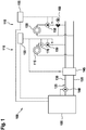
- FIG. 2 shows an exemplary further heating system 100 with two consumer circuits 110 with radiators 115 and two other load circuits 110 with underfloor heating 120.
- a flow sensor 170 is provided at each consumer circuit 110 and the provision of a request for a flow temperature of a load circuit 170 is suppressed, if the specific volume flow predetermined threshold, in particular zero, below.
- FIG. 3 3 shows a flow chart of a method 300 for controlling a heating system 100.
- the method 300 begins in a step 305. Subsequently, a required flow temperature is determined for each existing consumer circuit 110 in a step 310. In addition, for each consumer circuit 110 it is determined in a step 315 whether there is any heating demand at all. This is the case, for example, when the volume flow of fluid 125 through the consumer circuit 110 exceeds a predetermined threshold. In a step 320 performed for each consumer circuit 110, the particular request is provided only if the associated need also exists. The order of steps 310 to 320 may be varied and, for example, it may be waived a required one Flow temperature to determine if the heat demand is zero. The steps 310 to 320 of the individual consumer circuits 110 can be carried out independently of each other in time, also different times.
Landscapes
- Engineering & Computer Science (AREA)
- Physics & Mathematics (AREA)
- Thermal Sciences (AREA)
- Chemical & Material Sciences (AREA)
- Combustion & Propulsion (AREA)
- Mechanical Engineering (AREA)
- General Engineering & Computer Science (AREA)
- Steam Or Hot-Water Central Heating Systems (AREA)
Abstract
Description
- Die Erfindung betrifft eine Technik zur Steuerung eines Heizsystems. Insbesondere betrifft die Erfindung die Steuerung einer Vorlauftemperatur eines Heizsystems mit einem Heizgerät und einem Verbraucherkreis.
- Zum Heizen eines Hauses ist ein Heizsystem vorgesehen. Das Heizsystem umfasst ein Heizgerät und wenigstens einen Verbraucherkreis, wobei zwischen dem Heizgerät und den Verbraucherkreisen ein Fluid zirkuliert. Das Fluid wird im Heizgerät erwärmt, strömt durch einen Vorlauf in den Verbraucherkreis, kühlt dort ab und strömt durch einen Rücklauf wieder zurück ins Heizgerät. Dem Verbraucherkreis kann eine Vorlauftemperatur zugeordnet sein, die fest voreingestellt ist oder anhand von Parametern wie einer Innen- und einer Außentemperatur bestimmt werden kann. Insbesondere wenn mehrere Verbraucherkreise am gleichen Heizgerät betrieben werden kann dem Verbraucherkreis eine Steuervorrichtung zugeordnet sein, die eine Anforderung für die Vorlauftemperatur des Verbraucherkreises abgibt. Das Heizgerät wird dann so gesteuert, dass sich im Vorlauf die höchste der angeforderten Vorlauftemperaturen aller Verbraucherkreise einstellt. Benötigt der Verbraucherkreis eine geringere als diese Vorlauftemperatur, kann er kühleres Fluid aus dem Rücklauf mit dem heißen Fluid mischen, das durch das Heizgerät bereitgestellt ist.
- Eine der Erfindung zugrunde liegende Aufgabe besteht darin, eine verbesserte Technik zur Steuerung eines solchen Heizsystems bereitzustellen. Die Erfindung löst diese Aufgabe mittels der Gegenstände der unabhängigen Ansprüche. Unteransprüche geben bevorzugte Ausführungsformen wieder.
- Ein Heizsystem umfasst ein Heizgerät und einen Verbraucherkreis, zwischen denen ein Fluid zur Wärmeübertragung zirkuliert. Ein Verfahren zum Steuern eines Heizsystems umfasst Schritte des Bestimmens einer Anforderung für eine Vorlauftemperatur des Verbraucherkreises; und des Bereitstellen der Anforderung an das Heizgerät. Dabei wird die Anforderung nur bereitgestellt, falls im Verbraucherkreis ein Wärmebedarf vorliegt.
- Liegt kein Wärmebedarf im Verbraucherkreis vor, so wird auch keine Anforderung für die Vorlauftemperatur bereitgestellt. In diesem Fall kann das Heizgerät das Erhitzen des Fluids verringern oder einstellen. Ein Energieverbraucht kann so verringert werden. Wird das Heizgerät mit Brennstoff betrieben, so kann Brennstoff eingespart werden. Umfasst das Heizgerät eine Wärmepumpe, so kann ein Wirkungsgrad erhöht sein. Unter bestimmten Bedingungen kann eine Rücklauftemperatur am Heizgerät abgesenkt sein, wodurch das Heizgerät in einem günstigeren Temperaturbereich betrieben werden kann.
- Es ist bevorzugt, dass der Wärmebedarf bestimmt wird, falls ein Volumenstrom durch den Verbraucherkreis über einem vorbestimmten Schwellenwert liegt. Dieser Schwellenwert kann insbesondere einen kleinen Bruchteil eines maximalen Volumenstroms betragen, beispielsweise ca. 1 - 2 %, oder anderweitig sehr klein sein, nahe null liegen oder praktisch oder tatsächlich null entsprechen.
- Eine Steuervorrichtung für das oben genannte Heizsystem umfasst eine Abtastvorrichtung zur Bestimmung des Vorliegens eines Wärmebedarfs im Verbraucherkreis; und eine Verarbeitungseinrichtung, die dazu eingerichtet ist, eine Anforderung für eine vorbestimmte Vorlauftemperatur nur dann an das Heizgerät bereitzustellen, wenn ein Wärmebedarf vorliegt. Die Steuervorrichtung kann insbesondere dazu eingerichtet sein, das oben beschriebene Verfahren ganz oder teilweise durchzuführen. Dazu kann die Steuervorrichtung eine Verarbeitungseinrichtung umfassen, die beispielsweise als programmierbarer Mikrocomputer ausgeführt ist.
- Das Verfahren kann in Form eines Computerprogrammprodukts vorliegen und Programmcodemittel umfassen, die zur Durchführung des Verfahrens geeignet sind, wenn das Computerprogrammprodukt auf der Verarbeitungseinrichtung abläuft. Das Verfahren und die Steuervorrichtung bzw. das weiter unten beschriebene System können einander in Teilen oder vollständig entsprechen, sodass Merkmale oder Vorteile des Verfahrens auf die Steuervorrichtung oder das System angewandt werden können oder umgekehrt.
- In einer Ausführungsform ist die Abtastvorrichtung dazu eingerichtet, den Volumenstrom von Fluid durch den Verbraucherkreis zu bestimmen. Der bestimmte Volumenstrom kann dann mit einem Schwellenwert verglichen werden. In einer anderen Ausführungsform ist die Abtastvorrichtung dazu eingerichtet, das Vorliegen des Wärmebedarfs zu bestimmen, wenn ein Volumenstrom des Fluids durch den Verbraucherkreislauf einen vorbestimmten Schwellenwert übersteigt. Dabei kann die Abtastvorrichtung einfach und kostengünstig aufgebaut sein. Es kann beispielsweise genügen, die Abtastvorrichtung als Strömungsschalter aufzubauen, der lediglich ein binäres (=zweiwertiges) Signal bereitstellt, ob der Volumenstrom einen beispielsweise durch die Bauart des Strömungsschalters bedingten Schwellenwert übersteigt oder nicht. Der Schwellenwert ist in beiden Fällen bevorzugt im Wesentlichen null, wie oben genauer beschrieben ist.
- Das Heizsystem kann mehrere Verbraucherkreise umfassen, wobei jedem Verbraucherkreis eine Vorrichtung zur Anforderung einer vorbestimmten Vorlauftemperatur zugeordnet ist. Dabei ist das Heizgerät bevorzugt dazu eingerichtet, das Fluid auf die höchste der angeforderten Vorlauftemperaturen zu erwärmen. Bleibt die Anforderung einer Vorlauftemperatur eines der Verbraucherkreise aus, so kann das Heizgerät verbessert so gesteuert werden, dass die Anforderungen der einen oder mehreren verbleibenden Verbraucherkreise bezüglich der Vorlauftemperatur erfüllt werden.
- Zwei Verbraucherkreisen können unterschiedliche Vorlauftemperaturen zugeordnet sein. Insbesondere dann, wenn der Wärmebedarf des Verbraucherkreises mit der höheren zugeordneten Vorlauftemperatur nicht besteht, kann das Heizgerät die Vorlauftemperatur auf die Anforderung des anderen Verbraucherkreises absenken.
- Einer der Verbraucherkreise kann eine Mischeinrichtung zur Mischung von Fluid des Vorlaufs mit Fluid des Rücklaufs umfassen, um die angeforderte Vorlauftemperatur zu erreichen. Sind die angeforderten Vorlauftemperaturen der an das Heizgerät angeschlossenen Verbraucherkreise ähnlich oder sogar gleich, so kann auf das Mischen verzichtet werden.
- Zwischen dem Heizgerät und den Verbraucherkreisen kann eine hydraulische Weiche angeordnet sein. Die hydraulische Weiche dient der hydraulischen Entkoppelung der verschiedenen Verbraucherkreise, insbesondere wenn sie unterschiedliche Volumenströme oder unterschiedliche Vorlauftemperaturen erfordern. Unter bestimmten Umständen kann jedoch ein Rückfluss von erwärmtem Fluid durch die hydraulische Weiche in den Rücklauf erfolgen, sodass ein Temperaturunterschied zwischen dem Vorlauf und dem Rücklauf verringert ist. Ein Wirkungsgrad des Heizgeräts kann dadurch absinken, insbesondere falls es sich um ein Brennwertgerät oder eine Wärmepumpe handelt.
- Ein Heizsystem umfasst ein Heizgerät und einen Verbraucherkreis, zwischen denen ein Fluid zur Wärmeübertragung zirkuliert, sowie die oben beschrieben Steuervorrichtung.
- Die Erfindung wird nun mit Bezug auf die beigefügten Figuren genauer beschrieben, in denen:
- Fig. 1
- ein erstes Heizsystem;
- Fig. 2
- ein zweites Heizsystem; und
- Fig. 3
- ein Ablaufdiagramm eines Verfahrens zum Steuern eines Heizsystems darstellt.
-
Figur 1 zeigt ein Heizsystem 100, das bevorzugt zum Einsatz in einem Gebäude wie einem Ein- oder Mehrparteienhaus eingerichtet ist. Das Heizsystem 100 umfasst ein Heizgerät 105, das bevorzugt als Brennwertheizung durch das Verfeuern von Gas oder einem anderen Brennstoff realisiert ist. In einer weiteren Ausführungsform kann das Heizgerät 105 jedoch auch auf einem anderen Prinzip basieren, beispielsweise auf dem einer Wärmepumpe. - Das Heizsystem 100 umfasst ferner einen oder mehrere Verbraucherkreise 110. In
Figur 1 sind ein erster Verbraucherkreis 110 links und ein zweiter Verbraucherkreis 110 rechts dargestellt. Die Verbraucherkreise 110 können Wärme auf unterschiedliche Weisen abgeben. Beispielsweise kann der links dargestellte erste Verbraucherkreis 110 einen Radiator 115 und der rechts dargestellte zweite Verbraucherkreis 110 eine Fußbodenheizung 125 umfassen. Es können jedoch auch gleichartig aufgebaute Verbraucherkreise 110 vorgesehen sein. - Das Heizgerät 105 ist dazu eingerichtet, ein Fluid 125, üblicherweise Wasser, zu erwärmen und an einem Vorlauf 130 bereitzustellen. Das Fluid 125 strömt dann durch den wenigstens einen Verbraucherkreis 110 und gelangt über einen Rücklauf 135 zurück zum Heizgerät 105. Zur Steuerung eines zirkulierten Volumenstroms von Fluid 125 durch das Heizgerät 105 kann eine Pumpe 140 vorgesehen sein, die üblicherweise von einer Steuervorrichtung angesteuert wird, die auch eine Wärmeleistung des Heizgeräts 105 steuert.
- In der Ausführungsform von
Figur 1 sind mehrere Verbraucherkreise 110 zueinander parallel an den Vorlauf 130 und den Rücklauf 135 angeschlossen. Um das Heizgerät 105 hydraulisch von den Verbraucherkreisen 110 zu entkoppeln ist dann üblicherweise eine hydraulische Weiche 145 vorgesehen. Die hydraulische Weiche 145 ist im einfachsten Fall als vertikale Rohrleitung mit vorzugsweise großem Querschnitt und dadurch kleinem Druckverlust zwischen dem Vorlauf 130 und dem Rücklauf 135 ausgebildet. In der hydraulischen Weiche 145 bildet sich eine Temperaturschichtung aufgrund des Dichteunterschiedes von warmem und kaltem Fluid 125. Im oberen Bereich befindet sich warmes Fluid des Vorlaufs 130 und im unteren Bereich kälteres Fluid 125 des Rücklaufs 135. - Sind Volumenströme des Fluids 125 durch das Heizgerät 105 und durch die Verbraucherkreise 110 nicht gleich groß, so erfolgt in der hydraulischen Weiche 145 ein Ausgleich durch Mischen von Fluid 125 des Vorlaufs 130 und des Rücklaufs 135. Wenn der momentane Volumenstrom durch das Heizgerät 105 größer als der durch die Verbraucherkreise 160 ist, so wird dem rücklaufenden Fluid 125 aus dem Verbraucherkreis 160 eine Teilmenge des warmen Fluids 125 des Vorlaufs 130 beigemischt. Wird hingegen in den Verbraucherkreisen 160 ein größerer Volumenstrom umgewälzt als durch das Heizgerät 105, so wird das in den Verbraucherkreis 160 fließende wärmere Fluid 125 mit kälterem, rückfließendem Fluid 125 gemischt, sodass die Vorlauftemperatur der Verbraucherkreise 110 reduziert wird.
- Der durch einen Verbraucherkreis 110 fließende Volumenstrom kann individuell gesteuert werden, beispielsweise mittels einer Verbraucherpumpe 150. Der Volumenstrom kann beispielsweise in Abhängigkeit der Vorlauftemperatur oder einer Rücklauftemperatur sowie einer Innentemperatur des Hauses gesteuert werden. Der Verbraucherkreis 110 kann hierzu eine Steuervorrichtung 155 umfassen. Die Steuervorrichtung 155 ist bevorzugt dazu eingerichtet, in Abhängigkeit einer abzugebenden Wärmemenge eine Anforderung für eine Vorlauftemperatur an das Heizgerät 105 bzw. dessen Steuerung bereitzustellen. In einer weiteren Ausführungsform sind die Steuervorrichtungen 155 auch mit der Steuerung des Heizgeräts 105 integriert ausgeführt.
- Die Verbraucherkreise 110 können unterschiedliche Temperaturen des Fluids 125 im Vorlauf 130 erfordern. Beispielsweise kann im ersten Heizkreis 110 mit dem Radiator 115 die Vorlauftemperatur im Auslegungspunkt (z. B. bei einer Außentemperatur von -15 °C) bei ca. 50 °C bis 70 °C liegen, während die Vorlauftemperatur des zweiten Verbraucherkreises 110 mit der Fußbodenheizung 120 bei 30 °C bis 45 °C liegt. Das Heizgerät 105 wird üblicherweise dazu angesteuert, die Vorlauftemperatur auf das Maximum der von den Verbraucherkreisen 110 bzw. deren Steuervorrichtungen 155 angeforderten Vorlauftemperaturen zu steuern.
- Ein Verbraucherkreis 110, der eine geringere Vorlauftemperatur benötigt, kann mit einem Mischer 160 ausgestattet sein, der aus dem Verbraucherkreis 110 in den Rücklauf 135 rücklaufendes Fluid 125 mit aus dem Vorlauf 130 einströmendem Fluid 125 derart mischt, dass das in den Wärmetauscher 115, 120 eintretende Fluid 125 eine vorbestimmte Temperatur aufweist.
- Fordert beispielsweise der erste Verbraucherkreis 110 eine Vorlauftemperatur von 50 °C und der zweite Verbraucherkreis 110 eine Vorlauftemperatur von 70 °C an, so wird das Fluid 125 im Vorlauf 130 durch das Heizgerät 105 auf 50 °C aufgeheizt. Die Pumpe 140 fördert das Fluid 125 zur hydraulischen Weiche 145 und die Verbraucherpumpen 150 fördern es durch die Wärmetauscher 115 bzw. 120. Der Mischer 160 mischt zum warmen Fluid 125 im Vorlauf 130 kühleres Fluid 125 von beispielsweise 25 °C, das aus der Fußbodenheizung 120 austritt, hinzu, sodass sich für die Fußbodenheizung 120 eine Vorlauftemperatur von 30 °C ergibt.
- Es kann vorkommen, dass einer der Verbraucherkreise 110 keinen Wärmebedarf hat, weil der zugeordnete Volumenstrom null ist. Beispielsweise können alle Radiatoren des ersten Verbraucherkreises 110 geschlossen sein. Üblicherweise wird trotzdem eine vorbestimmte Vorlauftemperatur angefordert, die höher als die angeforderte Vorlauftemperatur eines anderen Verbraucherkreises 110 ist.
- Im vorliegenden Beispiel liegt der Volumenstrom durch den ersten Verbraucherkreis 110 bei null und der durch den zweiten Verbraucherkreis 110 bei 10 l/min nach dem Mischer 160. Bei den beispielhaft angegebenen Temperaturen und Volumenströmen stellt sich vor dem Mischer 160 des zweiten Verbraucherkreises 110 ein Volumenstrom von 4 l/min ein. Das Heizgerät 105 wird jedoch mit 14 l/min durchströmt, sodass Fluid 125 vom Vorlauf 130 durch die hydraulische Weiche 145 in den Rücklauf 135 strömt und sich dort mit Fluid 125 mischt, das von der Fußbodenheizung 120 mit beispielsweise 25 °C zurückströmt. Die Rücklauftemperatur ins Heizgerät 105 beträgt dadurch ca. 43 °C.
- Es wird vorgeschlagen, dass eine Anforderung eines Verbraucherkreises 110 zur Bereitstellung einer Vorlauftemperatur nur dann gegeben wird, wenn ein Volumenstrom durch den Verbraucherkreis 110 einen vorbestimmten Schwellenwert übersteigt, insbesondere wenn er über null liegt. Das Heizgerät 105 ist bevorzugt dazu eingerichtet, keine Heizleistung zu erbringen und bevorzugt auch die Pumpe 140 zu deaktivieren, falls keine Anforderung zur Bereitstellung einer Vorlauftemperatur vorliegt. Liegen mehrere Anforderungen vor, so wird die Vorlauftemperatur auf das Maximum der angeforderten Temperaturen gesteuert. Liegt nur eine Anforderung vor, so wird die Vorlauftemperatur auf diese Anforderung gesteuert.
- Im oben gegebenen Beispiel fällt die Anforderung (50 °C) des ersten Verbraucherkreises 110 weg und nur noch die Anforderung (35 °C) des zweiten Verbraucherkreises 110 liegt vor. Die Vorlauftemperatur wird daher auf 35 °C eingestellt. Der Mischer 160 des zweiten Verbraucherkreises 110 stellt das Beimischen von rückströmendem Fluid 125 ein und Volumenströme vor und hinter dem Mischer 160 sind mit ca. 10 l/min gleich groß. Der Volumenstrom durch das Heizgerät 105 liegt unverändert bei 14 l/min, der durch die hydraulische Weiche 145 ist aber signifikant kleiner, sodass die Rücklauftemperatur nur noch 28 °C beträgt.
- Gegenüber der oben beschriebenen herkömmlichen Vorgehensweise ist das eine Verringerung von 15 K. Beim einem Gas-Brennwert-Heizgerät 105 wirkt sich eine solche Rücklauftemperaturreduzierung mit einer Effizienzsteigerung von ca. 5%-Punkten aus. Wärmepumpen reagieren bezüglich Effizienz noch viel sensibler auf sich verändernde Vor- und Rücklauftemperaturen. Hier ist in einem solchen Fall mit einer um eine vielfaches verbesserten Effizienz zu rechnen.
- Es ist bevorzugt, dass die Bestimmung, ob der Volumenstrom durch einen Verbraucherkreis 110 einen vorbestimmten Wert unterschreitet, mittels eines Strömungssensors 170 durchgeführt wird. Der Strömungssensor 170 kann nur in den Verbraucherkreisen 110 vorgesehen sein, deren vorbestimmte Vorlauftemperatur höher als die eines anderen Verbraucherkreises 110 liegt. Beispielsweise können Strömungssensoren 170 an allen mit Radiatoren 115 ausgestatteten Verbraucherkreisen 110 vorgesehen sein, während Heizkreise 110 mit Fußbodenheizung 120 unverändert bleiben. Der Strömungssensor 170 kann einen Volumenstrom bestimmen, der dann mit einem vorbestimmten Schwellenwert verglichen wird. In einer kostengünstigeren Alternative kann ein Strömungsschalter 170 vorgesehen sein, der lediglich ein zweiwertiges Signal bereitstellt, ob der Volumenstrom den Schwellenwert übersteigt oder nicht. Dazu kann der Schwellenwert beispielsweise mechanisch vorbestimmt sein. In einer Variante ist der Schwellenwert am Strömungsschalter 170 einstellbar.
- Es ist zu beachten, dass das Unterdrücken der Anforderung einer Vorlauftemperatur durch einen Verbraucherkreis 110 unabhängig von Art, Anzahl und Zusammenstellung von Verbraucherkreisen 110 erfolgen kann. Ein Betrieb des Heizgeräts 105 kann dadurch minimiert werden. Insbesondere kann eine Reduktion des Wirkungsgrads des Heizgeräts 105 durch Anheben der Rücklauftemperatur vermieden werden.
-
Figur 2 zeigt ein beispielhaftes weiteres Heizsystem 100 mit zwei Verbraucherkreisen 110 mit Radiatoren 115 und zwei weiteren Verbraucherkreisen 110 mit Fußbodenheizungen 120. Hier ist an jedem Verbraucherkreis 110 ein Strömungssensor 170 vorgesehen und die Bereitstellung einer Anforderung einer Vorlauftemperatur eines Verbraucherkreises 170 wird unterdrückt, falls der bestimmte Volumenstrom einen vorbestimmten Schwellenwert, insbesondere null, unterschreitet. -
Figur 3 zeigt ein Ablaufdiagramm eines Verfahrens 300 zum Steuern eines Heizsystems 100. Das Verfahren 300 beginnt in einem Schritt 305. Anschließend wird für jeden vorhandenen Verbraucherkreis 110 in einem Schritt 310 eine benötigte Vorlauftemperatur bestimmt. Außerdem wird für jeden Verbraucherkreis 110 in einem Schritt 315 bestimmt, ob ein Heizbedarf überhaupt vorliegt. Dies ist beispielsweise der Fall, wenn der Volumenstrom an Fluid 125 durch den Verbraucherkreis 110 einen vorbestimmten Schwellenwert übersteigt. In einem für jeden Verbraucherkreis 110 durchgeführten Schritt 320 wird die bestimmte Anforderung nur dann bereitgestellt, falls der zugeordnete Bedarf auch gegeben ist. Die Reihenfolge der Schritte 310 bis 320 kann variiert werden und es kann beispielsweise darauf verzichtet werden, eine erforderliche Vorlauftemperatur zu bestimmen, falls der Wärmebedarf null ist. Die Schritte 310 bis 320 der einzelnen Verbraucherkreise 110 können zeitlich unabhängig voneinander durchgeführt werden, auch unterschiedlich oft.
Claims (10)
- Verfahren (300) zum Steuern eines Heizsystems (100) mit einem Heizgerät (105) und einem Verbraucherkreis (110), zwischen denen ein Fluid (125) zur Wärmeübertragung zirkuliert, wobei das Verfahren (300) folgende Schritte umfasst:- Bestimmen (310) einer Anforderung für eine Vorlauftemperatur des Verbraucherkreises (110); und- Bereitstellen (320) der Anforderung an das Heizgerät (105);dadurch gekennzeichnet, dass- die Anforderung nur bereitgestellt wird, falls im Verbraucherkreis (110) ein Wärmebedarf vorliegt.
- Verfahren (300) nach Anspruch 1, ferner umfassend ein Bestimmen (315) des Wärmebedarfs, falls ein Volumenstrom durch den Verbraucherkreis (110) über einem vorbestimmten Schwellenwert liegt.
- Steuervorrichtung (155) für ein Heizsystem (100) mit einem Heizgerät (105) und einem Verbraucherkreis (110), zwischen denen ein Fluid (125) zur Wärmeübertragung zirkuliert, wobei die Steuervorrichtung (155) folgendes umfasst:- eine Abtastvorrichtung (170) zur Bestimmung des Vorliegens eines Wärmebedarfs im Verbraucherkreis (110);- eine Verarbeitungseinrichtung (155), die dazu eingerichtet ist, eine Anforderung für eine vorbestimmte Vorlauftemperatur nur dann an das Heizgerät (105) bereitzustellen, wenn ein Wärmebedarf vorliegt.
- Steuervorrichtung (155) nach Anspruch 3, wobei die Abtastvorrichtung (170) dazu eingerichtet ist, das Vorliegen des Wärmebedarfs zu bestimmen, wenn ein Volumenstrom des Fluids (125) durch den Verbraucherkreis (110) einen vorbestimmten Schwellenwert übersteigt.
- Steuervorrichtung (155) nach Anspruch 4, wobei der Schwellenwert im Wesentlichen null ist.
- Steuervorrichtung (155) nach einem der Ansprüche 3 bis 5, wobei das Heizsystem mehrere Verbraucherkreise (110) umfasst, jedem Verbraucherkreis (110) eine Vorrichtung (155) zur Anforderung einer vorbestimmten Vorlauftemperatur zugeordnet ist und das Heizgerät (105) dazu eingerichtet ist, das Fluid (125) auf die höchste der angeforderten Vorlauftemperaturen zu erwärmen.
- Steuervorrichtung (155) nach Anspruch 6, wobei zwei Verbraucherkreisen (110) unterschiedliche Vorlauftemperaturen zugeordnet sind.
- Steuervorrichtung (155) nach Ansprüchen 6 und 7, wobei einer der Verbraucherkreise (110) eine Mischeinrichtung (160) zur Mischung von Fluid (125) des Vorlaufs (130) mit Fluid (125) des Rücklaufs (135) umfasst, um die angeforderte Vorlauftemperatur zu erreichen.
- Steuervorrichtung (155) nach einem der Ansprüche 3 bis 8, wobei zwischen dem Heizgerät (105) und den Verbraucherkreisen (110) eine hydraulische Weiche (145) angeordnet ist.
- Heizsystem, umfassend ein Heizgerät (105) und einen Verbraucherkreis (110), zwischen denen ein Fluid (125) zur Wärmeübertragung zirkuliert, und eine Steuervorrichtung (155) nach einem der Ansprüche 3 bis 9.
Applications Claiming Priority (1)
| Application Number | Priority Date | Filing Date | Title |
|---|---|---|---|
| DE102017203133.6A DE102017203133A1 (de) | 2017-02-27 | 2017-02-27 | Verfahren und Vorrichtung zur Steuerung eines Heizsystems |
Publications (2)
| Publication Number | Publication Date |
|---|---|
| EP3367005A1 true EP3367005A1 (de) | 2018-08-29 |
| EP3367005B1 EP3367005B1 (de) | 2022-01-26 |
Family
ID=61187154
Family Applications (1)
| Application Number | Title | Priority Date | Filing Date |
|---|---|---|---|
| EP18155484.1A Active EP3367005B1 (de) | 2017-02-27 | 2018-02-07 | Heizsystem |
Country Status (2)
| Country | Link |
|---|---|
| EP (1) | EP3367005B1 (de) |
| DE (1) | DE102017203133A1 (de) |
Families Citing this family (1)
| Publication number | Priority date | Publication date | Assignee | Title |
|---|---|---|---|---|
| DE102022133190A1 (de) * | 2022-12-14 | 2024-06-20 | Vaillant Gmbh | Verfahren zum Betreiben einer Heizungsanlage, Computerprogramm, Regel- und Steuergerät und Heizungsanlagen |
Citations (5)
| Publication number | Priority date | Publication date | Assignee | Title |
|---|---|---|---|---|
| DE102011001223A1 (de) * | 2011-03-11 | 2012-09-13 | SCHÜCO International KG | Heizungsanlage sowie Betriebsverfahren und Steuereinrichtung für eine Heizungsanlage |
| DE102012101850A1 (de) * | 2012-03-06 | 2013-09-12 | Stefan Jöken | Verfahren zur bedarfsgeführten Regelung eines Wärmeerzeugers in einer Heizungsanlage |
| DE102012208994A1 (de) * | 2012-05-29 | 2013-12-05 | Mattias Grosse | Vorrichtung zum Regeln der Raumtemperatur |
| EP2775370A2 (de) * | 2013-03-08 | 2014-09-10 | PAW GmbH & Co. KG | Vorrichtung zum Heizen von Räumen, umfassend zumindest eine zentrale Wärmequelle und umfassend den Räumen zugeordnete Heizkreise |
| DE102013105786A1 (de) * | 2013-06-05 | 2014-12-11 | Michael Jeromin | Verfahren zur Regelung einer Zentral-Heizungsanlage |
-
2017
- 2017-02-27 DE DE102017203133.6A patent/DE102017203133A1/de not_active Withdrawn
-
2018
- 2018-02-07 EP EP18155484.1A patent/EP3367005B1/de active Active
Patent Citations (5)
| Publication number | Priority date | Publication date | Assignee | Title |
|---|---|---|---|---|
| DE102011001223A1 (de) * | 2011-03-11 | 2012-09-13 | SCHÜCO International KG | Heizungsanlage sowie Betriebsverfahren und Steuereinrichtung für eine Heizungsanlage |
| DE102012101850A1 (de) * | 2012-03-06 | 2013-09-12 | Stefan Jöken | Verfahren zur bedarfsgeführten Regelung eines Wärmeerzeugers in einer Heizungsanlage |
| DE102012208994A1 (de) * | 2012-05-29 | 2013-12-05 | Mattias Grosse | Vorrichtung zum Regeln der Raumtemperatur |
| EP2775370A2 (de) * | 2013-03-08 | 2014-09-10 | PAW GmbH & Co. KG | Vorrichtung zum Heizen von Räumen, umfassend zumindest eine zentrale Wärmequelle und umfassend den Räumen zugeordnete Heizkreise |
| DE102013105786A1 (de) * | 2013-06-05 | 2014-12-11 | Michael Jeromin | Verfahren zur Regelung einer Zentral-Heizungsanlage |
Also Published As
| Publication number | Publication date |
|---|---|
| EP3367005B1 (de) | 2022-01-26 |
| DE102017203133A1 (de) | 2018-08-30 |
Similar Documents
| Publication | Publication Date | Title |
|---|---|---|
| EP3032181B1 (de) | Heizsystem mit warmwasserbereitstellung | |
| DE102015014378A1 (de) | Verfahren zur Regelung einer Kreiselpumpe sowie zugehöriges Pumpensystem | |
| EP2354677B1 (de) | Nutzung von Wärme aus den Fernwärmerücklauf | |
| DE112014001194T5 (de) | Heiz- und Heißwasserversorgungsvorrichtung | |
| DE202007018972U1 (de) | Anordnung zum Beheizen von Gebäuden mit einer Infrarotheizung | |
| DE102014016791B4 (de) | Verfahren zur hydraulischen Regelung mehrerer Heizkreisläufe am Verteilerbalken | |
| DE102010044535B4 (de) | Warmwasserbereitungsanlage und Verfahren zum Betreiben einer Warmwasserbereitungsanlage | |
| AT406081B (de) | Heizanlage | |
| DE60119551T2 (de) | Fernwärmeanordnung, lokale Einheit einer Fernwärmeanordnung, Steuereinheit für die lokale Einheit und Verfahren zum Betreiben einer Fernwärmeanordnung | |
| DE2754301A1 (de) | Heizeinrichtung | |
| EP3367005B1 (de) | Heizsystem | |
| DE4034917A1 (de) | Umlaufwasserheizer mit einem kupferwaermetauscher | |
| EP3800403B1 (de) | Verfahren zum betreiben einer heizvorrichtung, heizvorrichtung | |
| EP1207355B1 (de) | Zentrale Kühl- und/oder Heizvorrichtung für zumindest ein Gebäude | |
| EP2014992A1 (de) | Temperieranlagenverteiler | |
| DE10259279B3 (de) | Versorgungssystem für Heiz-oder Kühlwasser sowie Verfahren zum Betreiben desselben | |
| AT510390A2 (de) | Wärmeversorgungsanlage mit mehreren verbraucherkreisen | |
| WO2020228921A1 (de) | Verfahren zum betrieb eines temperierten zirkulationssystem sowie temperiertes zirkulationssystem | |
| EP3980695A1 (de) | Verfahren zum betrieb einer heizungsanlage mit einer wärmepumpe und heizungsanlage | |
| DE202016004616U1 (de) | System zur flächenmäßigen Wärmeübertragung und Verteiler eines solchen Systems | |
| DE102018115838A1 (de) | Verfahren zum Betrieb einer Temperieranlage, Temperieranlage sowie Messvorrichtung | |
| EP1710512B1 (de) | Verfahren zum Betreiben einer Heizanlage mit Mischer | |
| AT526014A1 (de) | Verfahren zum Kühlen oder Heizen von Räumen | |
| DE102018213258A1 (de) | Verfahren und Vorrichtung zur Steuerung eines Heizsystems | |
| AT410250B (de) | Massenstrom-stabilisierungsbrücke für ein warmwasserzirkulationssystem und warmwasserzirkulationssystem |
Legal Events
| Date | Code | Title | Description |
|---|---|---|---|
| PUAI | Public reference made under article 153(3) epc to a published international application that has entered the european phase |
Free format text: ORIGINAL CODE: 0009012 |
|
| STAA | Information on the status of an ep patent application or granted ep patent |
Free format text: STATUS: THE APPLICATION HAS BEEN PUBLISHED |
|
| AK | Designated contracting states |
Kind code of ref document: A1 Designated state(s): AL AT BE BG CH CY CZ DE DK EE ES FI FR GB GR HR HU IE IS IT LI LT LU LV MC MK MT NL NO PL PT RO RS SE SI SK SM TR |
|
| AX | Request for extension of the european patent |
Extension state: BA ME |
|
| STAA | Information on the status of an ep patent application or granted ep patent |
Free format text: STATUS: REQUEST FOR EXAMINATION WAS MADE |
|
| 17P | Request for examination filed |
Effective date: 20190228 |
|
| RBV | Designated contracting states (corrected) |
Designated state(s): AL AT BE BG CH CY CZ DE DK EE ES FI FR GB GR HR HU IE IS IT LI LT LU LV MC MK MT NL NO PL PT RO RS SE SI SK SM TR |
|
| STAA | Information on the status of an ep patent application or granted ep patent |
Free format text: STATUS: EXAMINATION IS IN PROGRESS |
|
| 17Q | First examination report despatched |
Effective date: 20191031 |
|
| RAP1 | Party data changed (applicant data changed or rights of an application transferred) |
Owner name: ROBERT BOSCH GMBH |
|
| GRAP | Despatch of communication of intention to grant a patent |
Free format text: ORIGINAL CODE: EPIDOSNIGR1 |
|
| STAA | Information on the status of an ep patent application or granted ep patent |
Free format text: STATUS: GRANT OF PATENT IS INTENDED |
|
| INTG | Intention to grant announced |
Effective date: 20210408 |
|
| GRAJ | Information related to disapproval of communication of intention to grant by the applicant or resumption of examination proceedings by the epo deleted |
Free format text: ORIGINAL CODE: EPIDOSDIGR1 |
|
| STAA | Information on the status of an ep patent application or granted ep patent |
Free format text: STATUS: EXAMINATION IS IN PROGRESS |
|
| INTC | Intention to grant announced (deleted) | ||
| GRAP | Despatch of communication of intention to grant a patent |
Free format text: ORIGINAL CODE: EPIDOSNIGR1 |
|
| STAA | Information on the status of an ep patent application or granted ep patent |
Free format text: STATUS: GRANT OF PATENT IS INTENDED |
|
| INTG | Intention to grant announced |
Effective date: 20211008 |
|
| GRAS | Grant fee paid |
Free format text: ORIGINAL CODE: EPIDOSNIGR3 |
|
| GRAA | (expected) grant |
Free format text: ORIGINAL CODE: 0009210 |
|
| STAA | Information on the status of an ep patent application or granted ep patent |
Free format text: STATUS: THE PATENT HAS BEEN GRANTED |
|
| AK | Designated contracting states |
Kind code of ref document: B1 Designated state(s): AL AT BE BG CH CY CZ DE DK EE ES FI FR GB GR HR HU IE IS IT LI LT LU LV MC MK MT NL NO PL PT RO RS SE SI SK SM TR |
|
| REG | Reference to a national code |
Ref country code: GB Ref legal event code: FG4D Free format text: NOT ENGLISH |
|
| REG | Reference to a national code |
Ref country code: CH Ref legal event code: EP |
|
| REG | Reference to a national code |
Ref country code: AT Ref legal event code: REF Ref document number: 1465563 Country of ref document: AT Kind code of ref document: T Effective date: 20220215 |
|
| REG | Reference to a national code |
Ref country code: IE Ref legal event code: FG4D Free format text: LANGUAGE OF EP DOCUMENT: GERMAN |
|
| REG | Reference to a national code |
Ref country code: DE Ref legal event code: R096 Ref document number: 502018008617 Country of ref document: DE |
|
| REG | Reference to a national code |
Ref country code: SE Ref legal event code: TRGR |
|
| REG | Reference to a national code |
Ref country code: LT Ref legal event code: MG9D |
|
| REG | Reference to a national code |
Ref country code: NL Ref legal event code: MP Effective date: 20220126 |
|
| PG25 | Lapsed in a contracting state [announced via postgrant information from national office to epo] |
Ref country code: NL Free format text: LAPSE BECAUSE OF FAILURE TO SUBMIT A TRANSLATION OF THE DESCRIPTION OR TO PAY THE FEE WITHIN THE PRESCRIBED TIME-LIMIT Effective date: 20220126 |
|
| PG25 | Lapsed in a contracting state [announced via postgrant information from national office to epo] |
Ref country code: RS Free format text: LAPSE BECAUSE OF FAILURE TO SUBMIT A TRANSLATION OF THE DESCRIPTION OR TO PAY THE FEE WITHIN THE PRESCRIBED TIME-LIMIT Effective date: 20220126 Ref country code: PT Free format text: LAPSE BECAUSE OF FAILURE TO SUBMIT A TRANSLATION OF THE DESCRIPTION OR TO PAY THE FEE WITHIN THE PRESCRIBED TIME-LIMIT Effective date: 20220526 Ref country code: NO Free format text: LAPSE BECAUSE OF FAILURE TO SUBMIT A TRANSLATION OF THE DESCRIPTION OR TO PAY THE FEE WITHIN THE PRESCRIBED TIME-LIMIT Effective date: 20220426 Ref country code: LT Free format text: LAPSE BECAUSE OF FAILURE TO SUBMIT A TRANSLATION OF THE DESCRIPTION OR TO PAY THE FEE WITHIN THE PRESCRIBED TIME-LIMIT Effective date: 20220126 Ref country code: HR Free format text: LAPSE BECAUSE OF FAILURE TO SUBMIT A TRANSLATION OF THE DESCRIPTION OR TO PAY THE FEE WITHIN THE PRESCRIBED TIME-LIMIT Effective date: 20220126 Ref country code: ES Free format text: LAPSE BECAUSE OF FAILURE TO SUBMIT A TRANSLATION OF THE DESCRIPTION OR TO PAY THE FEE WITHIN THE PRESCRIBED TIME-LIMIT Effective date: 20220126 Ref country code: BG Free format text: LAPSE BECAUSE OF FAILURE TO SUBMIT A TRANSLATION OF THE DESCRIPTION OR TO PAY THE FEE WITHIN THE PRESCRIBED TIME-LIMIT Effective date: 20220426 |
|
| PG25 | Lapsed in a contracting state [announced via postgrant information from national office to epo] |
Ref country code: PL Free format text: LAPSE BECAUSE OF FAILURE TO SUBMIT A TRANSLATION OF THE DESCRIPTION OR TO PAY THE FEE WITHIN THE PRESCRIBED TIME-LIMIT Effective date: 20220126 Ref country code: LV Free format text: LAPSE BECAUSE OF FAILURE TO SUBMIT A TRANSLATION OF THE DESCRIPTION OR TO PAY THE FEE WITHIN THE PRESCRIBED TIME-LIMIT Effective date: 20220126 Ref country code: GR Free format text: LAPSE BECAUSE OF FAILURE TO SUBMIT A TRANSLATION OF THE DESCRIPTION OR TO PAY THE FEE WITHIN THE PRESCRIBED TIME-LIMIT Effective date: 20220427 Ref country code: FI Free format text: LAPSE BECAUSE OF FAILURE TO SUBMIT A TRANSLATION OF THE DESCRIPTION OR TO PAY THE FEE WITHIN THE PRESCRIBED TIME-LIMIT Effective date: 20220126 |
|
| PG25 | Lapsed in a contracting state [announced via postgrant information from national office to epo] |
Ref country code: IS Free format text: LAPSE BECAUSE OF FAILURE TO SUBMIT A TRANSLATION OF THE DESCRIPTION OR TO PAY THE FEE WITHIN THE PRESCRIBED TIME-LIMIT Effective date: 20220526 |
|
| REG | Reference to a national code |
Ref country code: CH Ref legal event code: PL |
|
| REG | Reference to a national code |
Ref country code: BE Ref legal event code: MM Effective date: 20220228 |
|
| REG | Reference to a national code |
Ref country code: DE Ref legal event code: R097 Ref document number: 502018008617 Country of ref document: DE |
|
| PG25 | Lapsed in a contracting state [announced via postgrant information from national office to epo] |
Ref country code: SM Free format text: LAPSE BECAUSE OF FAILURE TO SUBMIT A TRANSLATION OF THE DESCRIPTION OR TO PAY THE FEE WITHIN THE PRESCRIBED TIME-LIMIT Effective date: 20220126 Ref country code: SK Free format text: LAPSE BECAUSE OF FAILURE TO SUBMIT A TRANSLATION OF THE DESCRIPTION OR TO PAY THE FEE WITHIN THE PRESCRIBED TIME-LIMIT Effective date: 20220126 Ref country code: RO Free format text: LAPSE BECAUSE OF FAILURE TO SUBMIT A TRANSLATION OF THE DESCRIPTION OR TO PAY THE FEE WITHIN THE PRESCRIBED TIME-LIMIT Effective date: 20220126 Ref country code: MC Free format text: LAPSE BECAUSE OF FAILURE TO SUBMIT A TRANSLATION OF THE DESCRIPTION OR TO PAY THE FEE WITHIN THE PRESCRIBED TIME-LIMIT Effective date: 20220126 Ref country code: LU Free format text: LAPSE BECAUSE OF NON-PAYMENT OF DUE FEES Effective date: 20220207 Ref country code: EE Free format text: LAPSE BECAUSE OF FAILURE TO SUBMIT A TRANSLATION OF THE DESCRIPTION OR TO PAY THE FEE WITHIN THE PRESCRIBED TIME-LIMIT Effective date: 20220126 Ref country code: DK Free format text: LAPSE BECAUSE OF FAILURE TO SUBMIT A TRANSLATION OF THE DESCRIPTION OR TO PAY THE FEE WITHIN THE PRESCRIBED TIME-LIMIT Effective date: 20220126 Ref country code: CZ Free format text: LAPSE BECAUSE OF FAILURE TO SUBMIT A TRANSLATION OF THE DESCRIPTION OR TO PAY THE FEE WITHIN THE PRESCRIBED TIME-LIMIT Effective date: 20220126 |
|
| PG25 | Lapsed in a contracting state [announced via postgrant information from national office to epo] |
Ref country code: AL Free format text: LAPSE BECAUSE OF FAILURE TO SUBMIT A TRANSLATION OF THE DESCRIPTION OR TO PAY THE FEE WITHIN THE PRESCRIBED TIME-LIMIT Effective date: 20220126 |
|
| PLBE | No opposition filed within time limit |
Free format text: ORIGINAL CODE: 0009261 |
|
| STAA | Information on the status of an ep patent application or granted ep patent |
Free format text: STATUS: NO OPPOSITION FILED WITHIN TIME LIMIT |
|
| 26N | No opposition filed |
Effective date: 20221027 |
|
| PG25 | Lapsed in a contracting state [announced via postgrant information from national office to epo] |
Ref country code: LI Free format text: LAPSE BECAUSE OF NON-PAYMENT OF DUE FEES Effective date: 20220228 Ref country code: IE Free format text: LAPSE BECAUSE OF NON-PAYMENT OF DUE FEES Effective date: 20220207 Ref country code: CH Free format text: LAPSE BECAUSE OF NON-PAYMENT OF DUE FEES Effective date: 20220228 |
|
| PG25 | Lapsed in a contracting state [announced via postgrant information from national office to epo] |
Ref country code: SI Free format text: LAPSE BECAUSE OF FAILURE TO SUBMIT A TRANSLATION OF THE DESCRIPTION OR TO PAY THE FEE WITHIN THE PRESCRIBED TIME-LIMIT Effective date: 20220126 Ref country code: BE Free format text: LAPSE BECAUSE OF NON-PAYMENT OF DUE FEES Effective date: 20220228 |
|
| PG25 | Lapsed in a contracting state [announced via postgrant information from national office to epo] |
Ref country code: IT Free format text: LAPSE BECAUSE OF FAILURE TO SUBMIT A TRANSLATION OF THE DESCRIPTION OR TO PAY THE FEE WITHIN THE PRESCRIBED TIME-LIMIT Effective date: 20220126 |
|
| PG25 | Lapsed in a contracting state [announced via postgrant information from national office to epo] |
Ref country code: HU Free format text: LAPSE BECAUSE OF FAILURE TO SUBMIT A TRANSLATION OF THE DESCRIPTION OR TO PAY THE FEE WITHIN THE PRESCRIBED TIME-LIMIT; INVALID AB INITIO Effective date: 20180207 |
|
| PG25 | Lapsed in a contracting state [announced via postgrant information from national office to epo] |
Ref country code: MK Free format text: LAPSE BECAUSE OF FAILURE TO SUBMIT A TRANSLATION OF THE DESCRIPTION OR TO PAY THE FEE WITHIN THE PRESCRIBED TIME-LIMIT Effective date: 20220126 Ref country code: CY Free format text: LAPSE BECAUSE OF FAILURE TO SUBMIT A TRANSLATION OF THE DESCRIPTION OR TO PAY THE FEE WITHIN THE PRESCRIBED TIME-LIMIT Effective date: 20220126 |
|
| PG25 | Lapsed in a contracting state [announced via postgrant information from national office to epo] |
Ref country code: MT Free format text: LAPSE BECAUSE OF FAILURE TO SUBMIT A TRANSLATION OF THE DESCRIPTION OR TO PAY THE FEE WITHIN THE PRESCRIBED TIME-LIMIT Effective date: 20220126 |
|
| PGFP | Annual fee paid to national office [announced via postgrant information from national office to epo] |
Ref country code: DE Payment date: 20250422 Year of fee payment: 8 |
|
| PG25 | Lapsed in a contracting state [announced via postgrant information from national office to epo] |
Ref country code: TR Free format text: LAPSE BECAUSE OF FAILURE TO SUBMIT A TRANSLATION OF THE DESCRIPTION OR TO PAY THE FEE WITHIN THE PRESCRIBED TIME-LIMIT Effective date: 20220126 |
|
| PGFP | Annual fee paid to national office [announced via postgrant information from national office to epo] |
Ref country code: SE Payment date: 20260218 Year of fee payment: 9 |
|
| PGFP | Annual fee paid to national office [announced via postgrant information from national office to epo] |
Ref country code: GB Payment date: 20260219 Year of fee payment: 9 |
|
| PGFP | Annual fee paid to national office [announced via postgrant information from national office to epo] |
Ref country code: AT Payment date: 20260216 Year of fee payment: 9 |
|
| PGFP | Annual fee paid to national office [announced via postgrant information from national office to epo] |
Ref country code: FR Payment date: 20260219 Year of fee payment: 9 |