EP3367025B1 - Abtauvorrichtung und kühlschrank damit - Google Patents
Abtauvorrichtung und kühlschrank damit Download PDFInfo
- Publication number
- EP3367025B1 EP3367025B1 EP16857644.5A EP16857644A EP3367025B1 EP 3367025 B1 EP3367025 B1 EP 3367025B1 EP 16857644 A EP16857644 A EP 16857644A EP 3367025 B1 EP3367025 B1 EP 3367025B1
- Authority
- EP
- European Patent Office
- Prior art keywords
- heater
- case
- heater case
- working fluid
- heat pipe
- Prior art date
- Legal status (The legal status is an assumption and is not a legal conclusion. Google has not performed a legal analysis and makes no representation as to the accuracy of the status listed.)
- Active
Links
Images











Classifications
-
- F—MECHANICAL ENGINEERING; LIGHTING; HEATING; WEAPONS; BLASTING
- F25—REFRIGERATION OR COOLING; COMBINED HEATING AND REFRIGERATION SYSTEMS; HEAT PUMP SYSTEMS; MANUFACTURE OR STORAGE OF ICE; LIQUEFACTION SOLIDIFICATION OF GASES
- F25D—REFRIGERATORS; COLD ROOMS; ICE-BOXES; COOLING OR FREEZING APPARATUS NOT OTHERWISE PROVIDED FOR
- F25D21/00—Defrosting; Preventing frosting; Removing condensed or defrost water
- F25D21/06—Removing frost
- F25D21/08—Removing frost by electric heating
-
- F—MECHANICAL ENGINEERING; LIGHTING; HEATING; WEAPONS; BLASTING
- F25—REFRIGERATION OR COOLING; COMBINED HEATING AND REFRIGERATION SYSTEMS; HEAT PUMP SYSTEMS; MANUFACTURE OR STORAGE OF ICE; LIQUEFACTION SOLIDIFICATION OF GASES
- F25B—REFRIGERATION MACHINES, PLANTS OR SYSTEMS; COMBINED HEATING AND REFRIGERATION SYSTEMS; HEAT PUMP SYSTEMS
- F25B39/00—Evaporators; Condensers
- F25B39/02—Evaporators
-
- F—MECHANICAL ENGINEERING; LIGHTING; HEATING; WEAPONS; BLASTING
- F25—REFRIGERATION OR COOLING; COMBINED HEATING AND REFRIGERATION SYSTEMS; HEAT PUMP SYSTEMS; MANUFACTURE OR STORAGE OF ICE; LIQUEFACTION SOLIDIFICATION OF GASES
- F25B—REFRIGERATION MACHINES, PLANTS OR SYSTEMS; COMBINED HEATING AND REFRIGERATION SYSTEMS; HEAT PUMP SYSTEMS
- F25B47/00—Arrangements for preventing or removing deposits or corrosion, not provided for in another subclass
- F25B47/02—Defrosting cycles
-
- F—MECHANICAL ENGINEERING; LIGHTING; HEATING; WEAPONS; BLASTING
- F25—REFRIGERATION OR COOLING; COMBINED HEATING AND REFRIGERATION SYSTEMS; HEAT PUMP SYSTEMS; MANUFACTURE OR STORAGE OF ICE; LIQUEFACTION SOLIDIFICATION OF GASES
- F25D—REFRIGERATORS; COLD ROOMS; ICE-BOXES; COOLING OR FREEZING APPARATUS NOT OTHERWISE PROVIDED FOR
- F25D21/00—Defrosting; Preventing frosting; Removing condensed or defrost water
- F25D21/06—Removing frost
- F25D21/12—Removing frost by hot-fluid circulating system separate from the refrigerant system
-
- F—MECHANICAL ENGINEERING; LIGHTING; HEATING; WEAPONS; BLASTING
- F28—HEAT EXCHANGE IN GENERAL
- F28D—HEAT-EXCHANGE APPARATUS, NOT PROVIDED FOR IN ANOTHER SUBCLASS, IN WHICH THE HEAT-EXCHANGE MEDIA DO NOT COME INTO DIRECT CONTACT
- F28D15/00—Heat-exchange apparatus with the intermediate heat-transfer medium in closed tubes passing into or through the conduit walls ; Heat-exchange apparatus employing intermediate heat-transfer medium or bodies
- F28D15/02—Heat-exchange apparatus with the intermediate heat-transfer medium in closed tubes passing into or through the conduit walls ; Heat-exchange apparatus employing intermediate heat-transfer medium or bodies in which the medium condenses and evaporates, e.g. heat pipes
- F28D15/0208—Heat-exchange apparatus with the intermediate heat-transfer medium in closed tubes passing into or through the conduit walls ; Heat-exchange apparatus employing intermediate heat-transfer medium or bodies in which the medium condenses and evaporates, e.g. heat pipes using moving tubes
-
- F—MECHANICAL ENGINEERING; LIGHTING; HEATING; WEAPONS; BLASTING
- F28—HEAT EXCHANGE IN GENERAL
- F28D—HEAT-EXCHANGE APPARATUS, NOT PROVIDED FOR IN ANOTHER SUBCLASS, IN WHICH THE HEAT-EXCHANGE MEDIA DO NOT COME INTO DIRECT CONTACT
- F28D15/00—Heat-exchange apparatus with the intermediate heat-transfer medium in closed tubes passing into or through the conduit walls ; Heat-exchange apparatus employing intermediate heat-transfer medium or bodies
- F28D15/02—Heat-exchange apparatus with the intermediate heat-transfer medium in closed tubes passing into or through the conduit walls ; Heat-exchange apparatus employing intermediate heat-transfer medium or bodies in which the medium condenses and evaporates, e.g. heat pipes
- F28D15/0266—Heat-exchange apparatus with the intermediate heat-transfer medium in closed tubes passing into or through the conduit walls ; Heat-exchange apparatus employing intermediate heat-transfer medium or bodies in which the medium condenses and evaporates, e.g. heat pipes with separate evaporating and condensing chambers connected by at least one conduit; Loop-type heat pipes; with multiple or common evaporating or condensing chambers
-
- F—MECHANICAL ENGINEERING; LIGHTING; HEATING; WEAPONS; BLASTING
- F28—HEAT EXCHANGE IN GENERAL
- F28D—HEAT-EXCHANGE APPARATUS, NOT PROVIDED FOR IN ANOTHER SUBCLASS, IN WHICH THE HEAT-EXCHANGE MEDIA DO NOT COME INTO DIRECT CONTACT
- F28D7/00—Heat-exchange apparatus having stationary tubular conduit assemblies for both heat-exchange media, the media being in contact with different sides of a conduit wall
- F28D7/0008—Heat-exchange apparatus having stationary tubular conduit assemblies for both heat-exchange media, the media being in contact with different sides of a conduit wall the conduits for one medium being in heat conductive contact with the conduits for the other medium
- F28D7/0016—Heat-exchange apparatus having stationary tubular conduit assemblies for both heat-exchange media, the media being in contact with different sides of a conduit wall the conduits for one medium being in heat conductive contact with the conduits for the other medium the conduits for one medium or the conduits for both media being bent
-
- F—MECHANICAL ENGINEERING; LIGHTING; HEATING; WEAPONS; BLASTING
- F28—HEAT EXCHANGE IN GENERAL
- F28F—DETAILS OF HEAT-EXCHANGE AND HEAT-TRANSFER APPARATUS, OF GENERAL APPLICATION
- F28F1/00—Tubular elements; Assemblies of tubular elements
- F28F1/10—Tubular elements and assemblies thereof with means for increasing heat-transfer area, e.g. with fins, with projections, with recesses
- F28F1/12—Tubular elements and assemblies thereof with means for increasing heat-transfer area, e.g. with fins, with projections, with recesses the means being only outside the tubular element
-
- F—MECHANICAL ENGINEERING; LIGHTING; HEATING; WEAPONS; BLASTING
- F28—HEAT EXCHANGE IN GENERAL
- F28F—DETAILS OF HEAT-EXCHANGE AND HEAT-TRANSFER APPARATUS, OF GENERAL APPLICATION
- F28F1/00—Tubular elements; Assemblies of tubular elements
- F28F1/10—Tubular elements and assemblies thereof with means for increasing heat-transfer area, e.g. with fins, with projections, with recesses
- F28F1/40—Tubular elements and assemblies thereof with means for increasing heat-transfer area, e.g. with fins, with projections, with recesses the means being only inside the tubular element
-
- F—MECHANICAL ENGINEERING; LIGHTING; HEATING; WEAPONS; BLASTING
- F28—HEAT EXCHANGE IN GENERAL
- F28F—DETAILS OF HEAT-EXCHANGE AND HEAT-TRANSFER APPARATUS, OF GENERAL APPLICATION
- F28F19/00—Preventing the formation of deposits or corrosion, e.g. by using filters or scrapers
- F28F19/006—Preventing deposits of ice
-
- F—MECHANICAL ENGINEERING; LIGHTING; HEATING; WEAPONS; BLASTING
- F25—REFRIGERATION OR COOLING; COMBINED HEATING AND REFRIGERATION SYSTEMS; HEAT PUMP SYSTEMS; MANUFACTURE OR STORAGE OF ICE; LIQUEFACTION SOLIDIFICATION OF GASES
- F25B—REFRIGERATION MACHINES, PLANTS OR SYSTEMS; COMBINED HEATING AND REFRIGERATION SYSTEMS; HEAT PUMP SYSTEMS
- F25B2400/00—Component parts or details not otherwise provided for in this subclass
- F25B2400/01—Heaters
-
- F—MECHANICAL ENGINEERING; LIGHTING; HEATING; WEAPONS; BLASTING
- F25—REFRIGERATION OR COOLING; COMBINED HEATING AND REFRIGERATION SYSTEMS; HEAT PUMP SYSTEMS; MANUFACTURE OR STORAGE OF ICE; LIQUEFACTION SOLIDIFICATION OF GASES
- F25D—REFRIGERATORS; COLD ROOMS; ICE-BOXES; COOLING OR FREEZING APPARATUS NOT OTHERWISE PROVIDED FOR
- F25D21/00—Defrosting; Preventing frosting; Removing condensed or defrost water
- F25D21/04—Preventing the formation of frost or condensate
-
- F—MECHANICAL ENGINEERING; LIGHTING; HEATING; WEAPONS; BLASTING
- F28—HEAT EXCHANGE IN GENERAL
- F28D—HEAT-EXCHANGE APPARATUS, NOT PROVIDED FOR IN ANOTHER SUBCLASS, IN WHICH THE HEAT-EXCHANGE MEDIA DO NOT COME INTO DIRECT CONTACT
- F28D1/00—Heat-exchange apparatus having stationary conduit assemblies for one heat-exchange medium only, the media being in contact with different sides of the conduit wall, in which the other heat-exchange medium is a large body of fluid, e.g. domestic or motor car radiators
- F28D1/02—Heat-exchange apparatus having stationary conduit assemblies for one heat-exchange medium only, the media being in contact with different sides of the conduit wall, in which the other heat-exchange medium is a large body of fluid, e.g. domestic or motor car radiators with heat-exchange conduits immersed in the body of fluid
- F28D1/04—Heat-exchange apparatus having stationary conduit assemblies for one heat-exchange medium only, the media being in contact with different sides of the conduit wall, in which the other heat-exchange medium is a large body of fluid, e.g. domestic or motor car radiators with heat-exchange conduits immersed in the body of fluid with tubular conduits
- F28D1/047—Heat-exchange apparatus having stationary conduit assemblies for one heat-exchange medium only, the media being in contact with different sides of the conduit wall, in which the other heat-exchange medium is a large body of fluid, e.g. domestic or motor car radiators with heat-exchange conduits immersed in the body of fluid with tubular conduits the conduits being bent, e.g. in a serpentine or zig-zag
- F28D1/0477—Heat-exchange apparatus having stationary conduit assemblies for one heat-exchange medium only, the media being in contact with different sides of the conduit wall, in which the other heat-exchange medium is a large body of fluid, e.g. domestic or motor car radiators with heat-exchange conduits immersed in the body of fluid with tubular conduits the conduits being bent, e.g. in a serpentine or zig-zag the conduits being bent in a serpentine or zig-zag
-
- F—MECHANICAL ENGINEERING; LIGHTING; HEATING; WEAPONS; BLASTING
- F28—HEAT EXCHANGE IN GENERAL
- F28D—HEAT-EXCHANGE APPARATUS, NOT PROVIDED FOR IN ANOTHER SUBCLASS, IN WHICH THE HEAT-EXCHANGE MEDIA DO NOT COME INTO DIRECT CONTACT
- F28D15/00—Heat-exchange apparatus with the intermediate heat-transfer medium in closed tubes passing into or through the conduit walls ; Heat-exchange apparatus employing intermediate heat-transfer medium or bodies
- F28D15/02—Heat-exchange apparatus with the intermediate heat-transfer medium in closed tubes passing into or through the conduit walls ; Heat-exchange apparatus employing intermediate heat-transfer medium or bodies in which the medium condenses and evaporates, e.g. heat pipes
- F28D2015/0216—Heat-exchange apparatus with the intermediate heat-transfer medium in closed tubes passing into or through the conduit walls ; Heat-exchange apparatus employing intermediate heat-transfer medium or bodies in which the medium condenses and evaporates, e.g. heat pipes having particular orientation, e.g. slanted, or being orientation-independent
-
- F—MECHANICAL ENGINEERING; LIGHTING; HEATING; WEAPONS; BLASTING
- F28—HEAT EXCHANGE IN GENERAL
- F28F—DETAILS OF HEAT-EXCHANGE AND HEAT-TRANSFER APPARATUS, OF GENERAL APPLICATION
- F28F1/00—Tubular elements; Assemblies of tubular elements
- F28F1/10—Tubular elements and assemblies thereof with means for increasing heat-transfer area, e.g. with fins, with projections, with recesses
- F28F1/12—Tubular elements and assemblies thereof with means for increasing heat-transfer area, e.g. with fins, with projections, with recesses the means being only outside the tubular element
- F28F1/24—Tubular elements and assemblies thereof with means for increasing heat-transfer area, e.g. with fins, with projections, with recesses the means being only outside the tubular element and extending transversely
Definitions
- the present disclosure relates to a defrosting device for removing frost formed on an evaporator provided in a refrigeration cycle, and a refrigerator having the same.
- An evaporator provided in a refrigeration cycle decreases ambient temperature using cool air generated by the circulation of coolant flowing through a cooling tube. During the process, when there occurs a temperature difference from ambient air, a phenomenon of condensing and freezing moisture in the air on a surface of the cooling tube occurs.
- a defrosting method using an electric heater has been used for a defrosting process for removing frost formed on an evaporator in the related art.
- a heat pipe type defrosting device in the aforementioned patent "Evaporator” has a configuration in which a heater is vertically disposed in the top-down direction of the evaporator, and working fluid is filled only into a bottom portion of the heater.
- the defrosting device with the foregoing structure may increase the evaporation speed due to rapid heating but has a danger of overheating the heater.
- the heater has a structure in which the heater is accommodated into the heat pipe, and thus high-temperature heat may be concentrated on an inside of the heat pipe, thereby reducing the lifespan of the heater as well as causing the sealing problem of the heater.
- JP H08303932 A discloses a defrosting means for a refrigerator.
- US 2 631 442 A discloses an automatic defrosting system.
- EP 3 343 135 A1 represents prior art according to Art. 54 (3) EPC and discloses a defroster.
- An aspect of the present disclosure is to provide a defrosting device with a new structure that can be fabricated at lower cost capable of reducing power consumption during defrosting, and facilitating maintenance.
- Another aspect of the present disclosure is to provide a defrosting device capable of enhancing the heat transfer performance of a heater as well as preventing the overheating of the heater to enhance reliability.
- Still another aspect of the present disclosure is to provide a defrosting device capable of preventing working fluid from being brought into contact with a heater.
- Yet still another aspect of the present disclosure is to provide a defrosting device capable of efficiently circulating working fluid.
- Still yet another aspect of the present disclosure is to provide a structure of efficiently carrying out defrosting for a lower cooling tube of an evaporator in a defrosting device in which a heating unit is vertically disposed along the top-down direction of the evaporator.
- a defrosting device includes a heating unit provided in an evaporator; and a heat pipe, both end portions of which are connected to an inlet and an outlet of the heating unit, respectively, and at least part of which is disposed adjacent to a cooling tube to dissipate heat to the cooling tube of the evaporator due to high-temperature working fluid heated and transferred by the heating unit, wherein the heating unit includes a heater case provided with a vacant space therein, and provided with the inlet and the outlet at positions separated from each other, respectively, along a length direction; and a heater attached to an outer surface of the heater case to heat working fluid within the heater case.
- the heater may be a plate-shaped heater having a plate shape.
- the heater includes a base plate formed of a ceramic material, and attached to an outer surface of the heater case; a hot wire formed on the base plate, and configured to dissipate heat during the application of power; and a terminal provided on the base plate to electrically connect the hot wire to the power.
- the heater case may be divided into an active heating part corresponding to a portion on which the hot wire is disposed and a passive heating part corresponding to a portion on which the hot wire is not disposed, and the inlet may be formed on the passive heating part to prevent working fluid being moved through the heat pipe and then returned through the inlet from being reheated to flow backward.
- the hot wire may be extended and formed from one point between the inlet and the outlet toward the outlet.
- the present disclosure discloses a first through a fourth embodiment of a defrosting device based on the structure.
- the heater may be attached to a bottom surface of the heater case.
- a first and a second extension fin extended and formed downward from a bottom surface and configured to cover both lateral surfaces of the heater attached to the bottom surface may be provided at both sides of the heater case, respectively.
- a sealing member may be filled to cover the heater on a rear surface of the heater and a recessed space formed by the first and the second extension fin.
- An insulating material may be interposed between the rear surface of the heater and the sealing member.
- a thermal conductive adhesive may be interposed between the heater case and the heater.
- the heater case may include a main case provided with a vacant space therein, both end portions of which have an open shape, and to a bottom surface of which the heater is adhered; and a first cover and a second cover mounted to cover both open end portions of the main case, respectively.
- At least one of the first and the second cover may be extended and formed downward from a bottom surface of the main case, and configured to surround the heater along with the first and the second extension fins.
- the outlet may include a first outlet and a second outlet connected to an end portion of the first and the second heat pipe, respectively, and the inlet may include a first inlet and a second inlet connected to the other end portion of the first and the second heat pipe, respectively.
- the first and the second outlet may be formed at both sides of the main case, respectively, or formed in parallel to each other to the first cover.
- the first and the second inlet may be formed at both sides of the main case, respectively, or formed in parallel to each other to the second cover.
- an outer fin may be protruded and formed on another outer surface of the heater case to which the heater is not adhered.
- the heater may be attached to a bottom surface of the heater case, and the outer fin may be formed on an upper surface of the heater case.
- a plurality of outer fins may be provided thereon, and extended and formed along a length direction or width direction of the heater case with a predetermined separation distance from each other.
- the separation distance may be set to be the same as or larger than a width of the outer fin.
- the plurality of outer fins may be provided thereon, and disposed with a predetermined separation distance from each other along a length direction and a width direction of the heater case to form a matrix.
- the outer fin may be protruded and formed on both outer surfaces of the main case, respectively, but extended and formed between the first inlet and the first outlet and the second inlet and the second outlet in an elongated manner.
- the outer fin may be also protruded and formed on an outer surface of at least one of the first and the second cover.
- an inner fin may be protruded and formed on an inner surface at an inner side of the outer surface to which the heater is adhered.
- the heater may be attached to an outer bottom surface of the heater case, and the inner fin may be protruded and formed from an inner bottom surface of the heater case.
- the inner fin may be protruded and formed with a length less than 1/2 compared to an inner height of the heater case.
- a plurality of inner fins may be provided thereon, and extended and formed along a length direction of the heater case with a predetermined separation distance from each other.
- a distance from an inner wall of the heater case to the inner fin adjacent to the inner wall may be formed to be greater than one time but less than two times compared to a width of the inner fin.
- a separation distance between each other of the plurality of inner fins may be formed to be greater than one time but less than two times compared to the width of the inner fin.
- the inner fin may be extended and formed between the first inlet and the first outlet and the second inlet and the second outlet in an elongated manner.
- the lead wire is extended outward from one end portion of the heater adjacent to an outer side of the evaporator.
- the heating unit In a structure in which the heating unit is disposed at a left bottom portion of the evaporator, it is configured such that the lead wire is extended outward from a left end portion of the heater adjacent to the left side of the evaporator.
- the terminal connected to the lead wire may be located at a left end portion of the heater.
- the heating unit In a structure in which the heating unit is disposed at a right bottom portion of the evaporator, it is configured such that the lead wire is extended outward from a right end portion of the heater adjacent to the right side of the evaporator.
- a right end portion of the heater may be disposed between the inlet and the outlet of the heater case, and the terminal connected to the lead wire may be located between the inlet and the outlet adjacent to the inlet of the heater case.
- the outlet may be formed at a position separated backward from a front end of the heater case with a predetermined distance in such a manner that to part of working fluid remains at a front end portion of the heater case to be brought into contact with the heater.
- an inner diameter of a return portion of the heat pipe connected to the inlet of the heater case may be formed to be greater than 5 mm but less than 7 mm.
- the heater case may be disposed such that an end portion of the inlet side has an angle range greater than -90° but less than 2° with respect to an end portion of the outlet side.
- the return portion may be disposed in parallel to the heater case or extended and formed in a downward direction of the heater case, and an entrance portion of the heat pipe connected to an outlet of the heater case may be disposed in parallel to the heater case or extended and formed in an upward direction of the heater case.
- the heater case is vertically disposed along a top-down direction at an outer side of a support fixture provided at one side of the evaporator, and the heater is located lower than a water level of working fluid filled into the heater case when the working fluid is all in a liquid phase.
- the heater may be attached to an opposite surface to one surface of the heater case facing the support fixture.
- the heat pipe is repeatedly bent in a zigzag shape to form a plurality of columns, and a distance between each column disposed at a lower portion of the heat pipe is smaller than that between each column disposed at an upper portion thereof.
- a distance between each column disposed at a lower portion of the first heat pipe at a front side of the evaporator may be formed to be smaller than that between each column disposed at an upper portion thereof, and a distance between each column disposed at an upper portion of the second heat pipe at a rear side of the evaporator may be formed to be smaller than that between each column disposed at a lower portion thereof.
- a distance between each column disposed at a lower portion of the first heat pipe at a front side of the evaporator may be formed to be larger than that between each column disposed at an upper portion thereof, and a distance between each column disposed at an upper portion of the second heat pipe at a rear side of the evaporator may be formed to be larger than that between each column disposed at a lower portion thereof.
- the heat pipe may include an evaporation unit connected to an outlet of the heating unit, and disposed to correspond to the cooling tube to transfer heat to the cooling tube; and a condensing unit extended from the evaporator and disposed lower than the lowest column of the cooling tube, and connected to an inlet of the heating unit.
- a lower end of the heating unit may be disposed adjacent to the lowest column of the cooling tube.
- At least part of the heating unit may be disposed lower than the lowest column of the cooling tube.
- the heater is attached to an outer surface of the heater case to heat working fluid within the heater case, thereby facilitating maintenance during the failure of the heater compared to a structure in which the heater is accommodated into the heater case. Furthermore, when a plate-shaped ceramic heater is applied to the heater, it may be possible to implement a defrosting device with a high efficiency at a lower cost.
- an outer area of the heater case may increase, thereby enhancing heat exchange efficiency between ambient low-temperature air and the heater case.
- a contact area to working fluid filled into the heater case may increase, thereby increasing a heat transfer rate of being transferred from the heater to working fluid.
- the entire volume of the heater case may increase to increase heat capacity capable of receiving heat from the heater case, thereby receiving more heat generated from the heater. As a result, it may be possible to enhance defrosting performance.
- outer fins and/or inner fins are formed as described above, a large amount of heat generated from the heater may be transferred to the heater case at a front side of the heater to prevent the overheating of the heater, and the temperature of a rear portion of the heater may decrease to enhance the reliability and lifespan of the heater.
- the sealing structure of the heater may be implemented by a structure in which the heater is attached to a bottom surface of the heater case, and a first and a second extension fin at both sides of the heater case are respectively extended and formed downward from the bottom surface, and a sealing member is filled into a recessed space formed by a rear surface of the heater and the first and the second extension fin.
- a return portion connected to the inlet of the heating unit may have an inner diameter greater than 5 mm but less than 7 mm. In this case, working fluid being returned may be efficiently introduced into the heater case, thereby preventing reheated working fluid from flowing backward.
- a structure capable of efficiently forming the flowing of working fluid reheated by the heater and discharged in a gas phase with a rising force while preventing reheated working fluid from flowing backward through a connection structure between the heating unit and the heat pipe for facilitating the flowing of working fluid in consideration of a rising characteristic of heated working fluid.
- At least part of the heating unit may be disposed lower than the evaporator, and a lower end of the heating unit may be preferably located adjacent to the lowest column of a horizontal pipe of the heating unit.
- a filling amount of working fluid may decrease, thereby increasing the temperature of the lowest column of the horizontal pipe of the heating unit up to a defrostable level.
- any one embodiment may be also applied in the same manner to another embodiment if they do not structurally or functionally contradict each other even in different embodiments.
- a singular representation may include a plural representation as far as it represents a definitely different meaning from the context.
- FIG. 1 is a longitudinal cross-sectional view schematically illustrating the configuration of a refrigerator 100 according to an embodiment of the present disclosure.
- the refrigerator 100 is a device for storing foods kept therein at low temperatures using cooling air generated by a less in which the processes of compression-condensation-expansion-evaporation are sequentially carried out.
- a refrigerator body 110 may include a storage space for storing foods therein.
- the storage space may be separated by a partition wall 111, and divided into a refrigerating chamber 112 and a freezing chamber 113 according to the set temperature.
- a top mount type refrigerator in which the freezing chamber 113 is disposed on the refrigerating chamber 112, but the present disclosure may not be necessarily limited to this.
- the present disclosure may be applicable to a side by side type refrigerator in which the refrigerating chamber and freezing chamber are horizontally disposed, a bottom freezer type refrigerator in which the refrigerating chamber is provided at the top and the freezing chamber is provided at the bottom, and the like.
- a door is connected to the refrigerator body 110 to open or close a front opening portion of the refrigerator body 110.
- a refrigerating chamber door 114 and a freezing chamber door 115 are configured to open or close a front portion of the refrigerating chamber 112 and freezing chamber 113, respectively.
- the door may be configured in various ways, such as a rotation type door in which a door is rotatably connected to the refrigerator body 110, a drawer type door in which a door is slidably connected to the refrigerator body 110, and the like.
- the refrigerator body 110 may include at least one of accommodation units 180 (for example, a shelf 181, a tray 182, a basket 183, etc.) for effectively using an internal storage space.
- accommodation units 180 for example, a shelf 181, a tray 182, a basket 183, etc.
- the shelf 181 and tray 182 may be installed within the refrigerator body 110
- the basket 183 may be installed at an inside of the door 114 connected to the refrigerator body 110.
- a cooling chamber 116 provided with an evaporator 130 and a blower fan 140 is provided at a rear side of the freezing chamber 113.
- a refrigerating chamber return duct 111a and a freezing chamber return duct 111b for inhaling and returning the air of the refrigerating chamber 112 and freezing chamber 113 to the side of the cooling chamber 116 are formed on the partition wall 111.
- a cool air duct 150 communicating with the freezing chamber 113 and having a plurality of cool air discharge ports 150a on a front portion thereof is installed at a rear side of the refrigerating chamber 112.
- a machine room 117 is provided at a rear lower side of the refrigerator body 110, and a compressor 160, a condenser (not shown) and the like are provided within the machine room 117.
- the process of inhaling the air of the refrigerating chamber 112 and freezing chamber 113 to the cooling chamber 116 through the refrigerating chamber return duct 111a and freezing chamber return duct 111b of the partition wall 111 by the blower fan 140 of the cooling chamber 116 to perform heat exchange with the evaporator 130, and discharging it to the refrigerating chamber 112 and freezing chamber 113 through the cool air discharge ports 150a of the cool air duct 150 again is repeatedly carried out.
- frost is formed on a surface of the evaporator 130 due to a temperature difference from circulation air reintroduced through the refrigerating chamber return duct 111a and the freezing chamber return duct 111b.
- a defrosting device 170 is provided in the evaporator 130 to remove such frost, and water removed by the defrosting device 170, namely, defrost water, is collected to a lower defrost water tray (not shown) of the refrigerator body 110 through a defrost water discharge pipe 118.
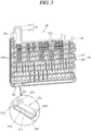
- FIGS. 2 and 3 are a front view and a perspective view illustrating a first embodiment of a defrosting device 170 applied to the refrigerator 100 in FIG. 1 .
- the evaporator 130 may include a cooling tube 131 (cooling pipe), a plurality of cooling fins 132, and support fixtures 133 at both sides.
- the cooling tube 131 is repeatedly bent in a zigzag shape to constitute a plurality of columns, and refrigerant is filled therein.
- the cooling tube 131 may be formed in an aluminum material.
- the cooling tube 131 may be configured in combination with horizontal pipe portions and bending pipe portions.
- the horizontal pipe portions are horizontally disposed to each other in a vertical direction, and configured to pass through the cooling fins 132, and the bending pipe portions connect an end portion of an upper horizontal pipe portion to an end portion of a lower horizontal pipe portion to communicate their inner portions with each other.
- the cooling tube 131 is supported through the support fixture 133 provided at both sides of the evaporator 130.
- the bending pipe portion of the cooling tube 131 is configured to connect an end portion of an upper horizontal pipe portion to an end portion of a lower horizontal pipe portion at an outer side of the support fixture 133.
- the cooling tube 131 is configured with a first cooling tube 131' and a second cooling tube 131" formed at a front portion and a rear portion of the evaporator 130, respectively, to constitute two columns.
- the first cooling tube 131' at a front side thereof and the second cooling tube 131" at a rear side thereof are formed with the same shape, and thus the second cooling tube 131" is hidden by the first cooling tube 131' in FIG. 2 .
- the first cooling tube 131' at a front side thereof and the second cooling tube 131" at a rear side thereof may be formed in different shapes.
- the cooling tube 131 may be formed to constitute a single column.
- a plurality of cooling fins 132 are disposed to be separated at predetermined intervals along an extension direction of the cooling tube 131.
- the cooling fin 132 may be formed with a flat body made of an aluminum material, and the cooling tube 131 may be flared in the state of being inserted into an insertion hole of the cooling fin 132, and securely inserted into the insertion hole.
- a plurality of support fixtures 133 may be provided at both sides of the evaporator 130, respectively, and each of which is configured to support the cooling tube 131 vertically extended and passed through along a vertical direction.
- An insertion groove or insertion hole to which a heat pipe 172 which will be described later can be inserted and fixed is formed on the support fixture 133.
- the defrosting device 170 is provided in the evaporator 130 to remove frost generated from the evaporator 130.
- the defrosting device 170 may include a heating unit 171 and a heat pipe 172 (heat transfer tube).
- the heating unit 171 is provided below the evaporator 130, electrically connected to the controller (not shown), and formed to generate heat upon receiving a drive signal from the controller.
- the controller may be configured to apply a drive signal to the heating unit 171 for each predetermined time interval or apply a drive signal to the heating unit 171 when the sensed temperature of the cooling chamber 116 is less than a predetermined temperature.
- the heat pipe 172 is connected to the heating unit 171 to form a closed loop shaped passage through which working fluid (F) can circulate along with the heating unit 171.
- the heat pipe 172 is formed of an aluminum material.
- the heat pipe 172 may include a first heat pipe 172' and a second heat pipe 172" disposed to constitute two columns at a front and a rear portion of the evaporator 130. According to the present example, it is seen a structure in which the first heat pipe 172' is disposed at a front side of the first cooling tube 131', and the second heat pipe 172" is disposed at a rear side of the second cooling tube 131" to constitute two columns.
- refrigerant for example, R-134a, R-600a, etc.
- refrigerant for example, R-134a, R-600a, etc.
- FIG. 4 is an exploded perspective view illustrating an example of the heating unit 171 illustrated in FIG. 3
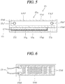
- FIG. 5 is a cross-sectional view in which the heating unit 171 illustrated in FIG. 4 is taken along a length direction
- FIG. 6 is a conceptual view illustrating the heater 171b illustrated in FIG. 4 .
- the heating unit 171 may include a heater case 171a and a heater 171b.
- the heater case 171a has a hollow shape therein, and is connected to both end portions of the heat pipe 172, respectively, to form a closed loop shaped passage through which working fluid (F) can circulate along with the heat pipe 172.
- the heater case 171a may have a rectangular pillar shape, and formed of an aluminum material.
- the heater case 171a may be disposed at one side of the evaporator 130 at which the accumulator 134 is located, the other side opposite the one side, or at any point between the one side and the other side.
- the heater case 171a may be disposed adjacent to the lowest column of the cooling tube 131.
- the heater case 171a may be disposed at the same height as the lowest column of the cooling tube 131 or disposed at a position lower than the lowest column of the cooling tube 131.
- the heater case 171a is disposed in a horizontal direction of the evaporator 130 in parallel to the cooling tube 131 at a position lower than the lowest column of the cooling tube 131 at one side of the evaporator 130 at which the accumulator 134 is located.
- the outlet 171c', 171c" and the inlet 171d', 171d" connected to both end portions of the heat pipe 172, respectively, are formed at both sides of the heater case 171a, respectively, in a length direction.
- the outlet 171c', 171c" communicated with one end portion of the heat pipe 172 is formed at one side of the heater case 171a (for example, an outer circumferential surface adjacent to a front end portion of the heater case 171a).
- the outlet 171c', 171c" denotes an opening through which working fluid (F) heated by the heater 171b is discharged to the heat pipe 172.
- the inlet 171d', 171d" communicated with the other end portion of the heat pipe 172 is formed at the other side of the heater case 171a (for example, an outer circumferential surface adjacent to a rear end portion of the heater case 171a).
- the inlet 171d', 171d” denotes an opening through which condensed working fluid (F) is collected to the heater case 171a while passing through the heat pipe 172.
- the heater 171b is attached to an outer surface of the heater case 171a, and configured to generate heat upon receiving a drive signal from the controller.
- Working fluid (F) within the heater case 171a receives heat due to the heater 171b to be heated at high temperatures.
- the heater 171b is extended and formed along one direction, and has a shape of being attached to an outer surface of the heater case 171a and extended along a length direction of the heater case 171a.
- a plate-shaped heater for example, a plate-shaped ceramic heater having a plate shape is used for the heater 171b.
- the heater case 171a is formed in a rectangular pipe shape in which a vacant space therein has a rectangular cross-sectional shape, and it is shown that a plate-shaped heater 171b is attached to a bottom surface of the heater case 171a.
- the structure in which the heater 171b is attached to a bottom surface of the heater case 171a may be beneficial in generating a driving force in an upward direction on the heated working fluid (F), and defrost water generated due to the defrost operation may not directly fall onto the heater 171b, thereby preventing a short circuit.
- a hot wire 171b2 (refer to FIG. 6 ) is formed on the heater 171b, and configured to generate heat while supplying power.
- the heater case 171a is divided into an active heating part (AHP) corresponding to a portion on which the hot wire 171b2 is disposed and a passive heating part (PHP) corresponding to a portion on which the hot wire 171b2 is not disposed.
- AHP active heating part
- PHP passive heating part
- the heat pipe 172 and heater case 171a may be formed of the same type material (for example, aluminum material), and in this case, the heat pipe 172 may be directly connected to the outlet 171c', 171c" and the inlet 171d', 171d" of the heater case 171a.
- the heater case 171a with a copper material other than an aluminum material will be used to bond and seal between the heater 171b and the heater case 171a.
- the heat pipe 172 and the heater case 171a are formed of different types of materials (as described above, when the heat pipe 172 is formed of an aluminum material, and the heater case 171a is formed of a copper material), it is difficult to directly connect the heat pipe 172 to the outlet 171c', 171c" and the inlet 171d', 171d” of the heater case 171a. Accordingly, for the connection between them, an outlet tube is extended and formed to the outlet 171c', 171c" of the heater case 171a, and a return tube is extended and formed to the inlet 171d', 171d" to connect the heat pipe 172 to the outlet tube and the return tube, and thus the bonding and sealing process is required for the procedure.
- the heater case 171a may be formed of the same material as that of the heat pipe 172, and the heat pipe 172 may be directly connected to the outlet 171c', 171c" and the inlet 171d', 171d" of the heater case 171a.
- the working fluid (F) filled into the heater case 171a is heated to high temperatures by the heater 171b
- the working fluid (F) flows due to a pressure difference to move the heat pipe 172.
- the working fluid (F) at high temperatures heated by the heater 171b and discharged to the outlet 171c', 171c" transfers heat to the cooling tube 131 of the evaporator 130 while moving through the heat pipe 172.
- the working fluid (F) is gradually cooled while passing through the heat exchange process and introduced into the inlet 171d', 171d".
- the cooled working fluid (F) is reheated by the heater 171b and then discharged to the outlet 171c', 171c" again to repeatedly perform the foregoing processes.
- the defrosting of the cooling tube 131 is carried out due to such a circulation method.
- At least part of the heat pipe 172 is disposed adjacent to the cooling tube 131 of the evaporator 130, and configured to transfer heat to the cooling tube 131 of the evaporator 130 due to high-temperature working fluid (F) heated and transferred by the heating unit 171 to remove frost.
- F high-temperature working fluid
- the heat pipe 172 may have a shape of being repeatedly bent (a zigzag shape) similarly to the cooling tube 131. To this end, the heat pipe 172 may include an extension portion 172a and a heat emitting part 172b.
- the extension portion 172a forms a passage for transferring working fluid (F) heated by the heating unit 171 in an upward direction of the evaporator 130.
- the extension portion 172a is connected to an outlet 171c', 171c" of the heater case 171a provided below the evaporator 130 and the heat emitting part 172b provided on the evaporator 130.
- the extension portion 172a may include a vertical extension portion extended in an upward direction of the evaporator 130.
- the vertical extension portion is extended up to an upper portion of the evaporator 130 in the state of being disposed to be separated from the support fixture 133 at an outer side of the support fixture 133 provided at one side of the evaporator 130.
- the extension portion 172a may further include a horizontal extension portion according to the installation position of the heating unit 171.
- a horizontal extension portion for connecting the heating unit 171 to the vertical extension portion may be additionally provided.
- high-temperature working fluid (F) may pass through a lower portion of the evaporator 130, thereby having an advantage of efficiently implementing a defrost operation on the cooling tube 131 at a lower side of the evaporator 130.
- the heat emitting part 172b is connected to the extension portion 172a extended to an upper portion of the evaporator 130, and extended in a zigzag shape along the cooling tube 131 of the evaporator 130.
- the heat emitting part 172b is configured in combination with a plurality of horizontal tubes 172b' constituting columns and a connecting tube 172b" formed in a bent U-shaped tube to connect them in a zigzag shape.
- the extension portion 172a or heat emitting part 172b may be extended up to a position adjacent to an accumulator 134 to remove frost formed on the accumulator 134.
- the vertical extension portion when the vertical extension portion is disposed at one side of the evaporator 130 at which the accumulator 134 is located, the vertical extension portion may be extended upward to a position adjacent to the accumulator 134, and then bent and extended downward toward the cooling tube 131 to be connected to the heat emitting part 172b.
- the heat emitting part 172b may be connected to the vertical extension portion and extended in a horizontal direction, and then extended upward toward the accumulator 134, and then extended downward again to correspond to the cooling tube 131.
- a portion connected to the outlet 171c'. 171c" of the heater case 171a constitutes an entrance portion 172c', 172c" for introducing high-temperature working fluid (F), and a portion connected to the inlet 171d', 171d" of the heater case 171a constitutes a return portion 172d', 172d" for returning the cooled working fluid (F).
- working fluid (F) heated by the heater 171b forms a circulation loop in which the working fluid (F) is discharged to the entrance portion 172c', 172c" and transferred to an upper portion of the evaporator 130 through the extension portion 172a, and then heat is transferred to the cooling tube 131 while flowing along the heat emitting part 172b to perform a defrost operation, and then the working fluid (F) is returned through the return portion 172d', 172d", and reheated by the heater 171b again to flow the heat pipe 172.
- the first and the second heat pipe 172', 172" are connected to the inlet 171d', 171d" and the outlet 171c', 171c" of the heating unit 171, respectively.
- the outlet 171c', 171c" of the heating unit 171 is configured with a first outlet 171c' and a second outlet 171c", and one end portion of the first and the second heat pipe 172', 172", respectively, is connected to the first and the second outlet 171c', 171c", respectively. Due to the foregoing connection structure, working fluid (F) in the gas phase heated by the heating unit 171 is discharged to the first and the second heat pipe 172', 172", respectively, through the first and the second outlet 171c', 171c".
- the first and the second outlet 171c', 171c" may be formed at both sides of an outer circumference of the heater case 171a, respectively, and formed in parallel at a front portion of the heater case 171a.
- first and the second heat pipe 172', 172" connected to the first and the second outlet 171c', 171c", respectively, is the first and the second entrance portions 172c', 172c" (a portion to which working fluid (F) at high temperatures heated by the heater 171b is introduced) due to the function.
- the inlet 171d', 171d" of the heating unit 171 is configured with a first inlet 171d' and a second inlet 171d", and the other end of the first and the second heat pipe 172', 172", respectively, is connected to the inlet 171d', 171d", respectively. Due to the connection structure, working fluid (F) in the liquid phase cooled while moving the heat pipes 172, respectively, is introduced into the heater case 171a through the first and the second inlet 171d', 171d".
- the first and the second inlet 171d', 171d" may be formed at both sides of an outer circumference of the heater case 171a, respectively, and formed in parallel at a rear portion of the heater case 171a.
- first and the second heat pipe 172', 172" connected to the inlet 171d', 171d", respectively, is the first and the second return portions 172d', 172d" (a portion to which working fluid (F) in the liquid phase cooled while moving through the heat pipes 172, respectively, is collected) due to the function.
- the outlet 171c', 171c" of the heater case 171a may be formed at a position separated by a predetermined distance from a front end of the heater case 171a in a backward direction.
- the front end portion of the heater case 171a is protruded and formed in a forward direction from the outlet 171c', 171c".
- the hot wire 171b2 of the heater 171b may be extended and formed from one point between the inlet 171d', 171d" and the outlet 171c', 171c" to a position passed through the outlet 171c', 171c". According to this, the outlet 171c', 171c" of the heater case 171a is located within the active heating part (AHP).
- part of working fluid (F) stays at a front end portion (a space between an inner front end and the outlet 171c', 171c" of the heater case 171a) to prevent the overheating of the heater 171b.
- working fluid (F) heated by the active heating part (AHP) moves in a direction through which the working fluid (F) circulates, namely, toward a front end portion of the heater case 171a, and during this process, part of the working fluid (F) is discharged to the branched outlet 171c', 171c", but the remaining working fluid passes through the outlet 171c', 171c" and stays while forming a vortex at a front end portion of the heater case 171a.
- the whole of the heated working fluid (F) is not immediately discharged to the outlet 171c', 171c", but part thereof stays within the heater case 171a without being immediately discharged to the outlet 171c', 171c", thereby further preventing the overheating of the heater 171b.
- the heat pipe 172 may be accommodated between a plurality of cooling fins 132 fixed to each column of the cooling tube 131. According to the foregoing structure, the heat pipe 172 is disposed between each column of the cooling tube 131. Here, the heat pipe 172 may be configured to make contact with the cooling fin 132.
- the heat pipe 172 may be provided to pass through a plurality of cooling fins 132.
- the heat pipe 172 may be flared in the state of being inserted into an insertion hole of the cooling fin 132, and securely inserted into the insertion hole.
- the heat pipe 172 is disposed to correspond to the cooling tube 131.
- the heater 171b applied to the heating unit 171 of the present disclosure may be formed in a plate shape, and a plate-shaped ceramic heater 171b may be typically used.
- the heater 171b includes a base plate 171b1, a hot wire 171b2 and a terminal 171b3.
- the base plate 171b1 is formed of a ceramic material, and formed in a plate shape extended in an elongated manner along one direction.
- the base plate 171b1 is attached to an outer surface of the heater case 171a, and disposed along a length direction of the heater case 171a.
- the hot wire 171b2 is formed on the base plate 171bl, and the hot wire 171b2 is configured to emit heat during the application of power.
- the hot wire 171b2 In a state that the base plate 171b1 is attached to an outer surface of the heater case 171a, the hot wire 171b2 has a shape of being extended from one point between the inlet 171d', 171d" and the outlet 171c', 171c" toward the outlet 171c', 171c".
- the hot wire 171b2 may be formed by patterning a resistor (for example, powder mixed with ruthenium and platinum, tungsten, etc.) on the base plate 171b1 with a specific pattern.
- the hot wire 171b2 may be extended and formed along a length direction of the baseplate 171b1.
- a terminal 171b3 configured to electrically connect the hot wire 171b2 to power is provided at one side of the base plate 171b1, and a lead wire 173 electrically connected to the power is connected to the terminal 171b3.
- the heater case 171a is divided into an active heating part (AHP) corresponding to a portion on which the hot wire 171b2 is disposed and a passive heating part (PHP) corresponding to a portion on which the hot wire 171b2 is not disposed.
- AHP active heating part
- PGP passive heating part
- the active heating part (AHP) is a portion directly heated by the hot wire 171b2, and working fluid (F) at the liquid phase is heated by the active heating part (AHP) and phase-changed into the gas phase at high temperatures.
- the outlet 171c', 171c" of the heater case 171a may be located within the active heating part (AHP) or located at a front side than the active heating part (AHP).
- AHP active heating part
- FIG. 6 it is illustrated that a portion formed with the hot wire 171b2 of the heater 171b is extended and formed in a forward direction through a lower portion of the outlet 171c', 171c" formed on an outer circumference of the heater case 171a.
- the outlet 171c', 171c" of the heater case 171a is located within the active heating part (AHP).
- the passive heating part (PHP) is formed at a rear side of the active heating part (AHP).
- the passive heating part (PHP) indirectly receives heat to be heated to a predetermined temperature level though it is not a portion directly heated by the hot wire 171b2 like the active heating part (AHP).
- the passive heating part causes a predetermined temperature increase to the working fluid (F) in the liquid phase, but does not have high temperatures to the extent of phase-changing the working fluid (F) to the gas phase.
- the active heating part (AHP) forms a relatively high-temperature portion and the passive heating part forms a relatively low-temperature portion.
- working fluid (F) is configured to directly return to a side of the active heating part (AHP) at high temperatures, then it may occur a case where the collected working fluid (F) is reheated and flowed backward without being efficiently returned into the heater case 171a. It may be an obstacle to the circulation flow of the working fluid (F) within the heat pipe 172, thereby causing a problem of overheating the heater 171b.
- the inlet 171d', 171d" of the heating unit 171 is formed to correspond to the passive heating part (PHP) not to allow working fluid (F) that has moved through the heat pipe 172 and then returned to be immediately introduced into the active heating part (AHP).
- the inlet 171d', 171d" of the heating unit 171 is located within the passive heating part (PHP) to allow working fluid (F) that has moved through the heat pipe 172 and then returned to be introduced into the passive heating part (PHP).
- the inlet 171d', 171d" of the heating unit 171 is formed at a portion on which the hot wire 171b2 is not disposed on the heater case 171a.
- the passive heating part is associated with the formation location of the hot wire 171b2. Accordingly, if the hot wire 171b2 is not extended and formed up to the inlet 171d', 171d" of the heating unit 171, then the base plate 171b1 of the heater 171b may be extended and formed up to a portion corresponding to the inlet 171d', 171d". In other words, the base plate 171b1 may be disposed to cover the most bottom surface of the heater case 171a, and the hot wire 171b2 may be formed at a position out of the inlet 171d', 171d", thereby preventing working fluid (F) returned through the inlet 171d', 171d" from flowing backward.
- working fluid F
- the heater case 171a may include a main case 171a1, a first cover 171a2 and a second cover 171a3 coupled to both sides of the main case 171a1, respectively.
- the main case 171a1 is provided with a vacant space therein, and has a shape in which both end portions thereof are open.
- the main case 171a1 may be formed of an aluminum material.
- FIG. 5 it is illustrated the main case 171a1 in a rectangular pillar shape in which a vacant space therein having a rectangular cross-sectional shape is extended and formed in an elongated manner along one direction.
- the first and the second cover 171a2, 171a3 are mounted at both sides of the main case 171a1 to cover both end portions of the main case 171a1 that are open.
- the first and the second cover 171a2, 171a3 may be formed of an aluminum material like the main case 171a1.
- the outlet 171c', 171c" and the inlet 171d', 171d" are provided at positions separated from each other along a length direction of the main case 171a1, respectively, and the both end portions (the entrance portion 172c', 172c" connected to the outlet 171c', 171c” and the return portion 172d', 172d" connected to the inlet 171d', 171d") of the heat pipe 172 are connected to the outlet 171c', 171c" and the inlet 171d', 171d".
- first outlet 171c' and the first inlet 171d' are formed at positions separated from each other along a length direction on one lateral surface of the main case 171a1
- second outlet 171c" and the second inlet 171d" are formed at positions separated from each other along a length direction on the other lateral surface facing the one surface.
- first outlet 171c' and the second outlet 171c" may be disposed to face each other
- first inlet 171d' and the second inlet 171d" may be disposed to face each other.
- At least one of the inlet 171d', 171d" and the outlet 171c', 171c" may be formed on a first and/or a second cover 171a2, 171a3. A structure associated therewith will be described in more detail later.
- the heating unit 171 is provided below the evaporator 130, and thus defrost water generated due to defrosting in the aspect of the structure may flow down to the heating unit 171.
- the heater 171b provided in the heating unit 171 is an electronic component, and thus when defrost water is brought into contact with the heater 171b, it may cause a short circuit.
- the heating unit 171 of the present disclosure may include the following sealing structure to prevent moisture including defrost water from infiltrating into the heater 171b.
- the heater 171b is attached to a bottom surface of the main case 171a1, and a first and a second extension pin 171ala, 171alb extended and formed in a downward direction from the bottom surface to cover a lateral surface of the heater 171b attached to the bottom surface are configured at both sides of the main case 171a1. Due to the structure, even when defrost water generated due to defrosting falls onto the main case 171a1 and flows down along an outer surface of the main case 171a1, the defrost water does not infiltrate into the heater 171b accommodated at an inner side of the first and the second extension pin 171ala, 171alb.
- a sealing member 171e may be filled into a recessed space 171a1' formed by a rear surface of the heater 171b and the first and the second extension pin 171ala, 171alb as described above. Silicon, urethane, epoxy or the like may be used for the sealing member 171e.
- epoxy in the liquid phase may be filled into the recessed space 171a1' and then subject to the curing process to complete the sealing structure of the heater 171b.
- the first and the second extension pin 171ala, 171alb may function as a sidewall limiting the recessed space 171a1' into which the sealing member 171e is filled.
- An insulating material 171f may be interposed between a rear surface of the heater 171b and the sealing member 171e.
- a mica sheet with a mica material may be used for the insulating material 171f.
- the insulating material 171f may be disposed on a rear surface of the heater 171b, thereby limiting heat from being transferred to a side of the rear surface of the heater 171b when the hot wire 171b2 emits heat according to the application of power.
- a thermally conductive adhesive 171g may be interposed between the main case 171a1 and the heater 171b.
- the thermally conductive adhesive 171g may attach the heater 171b to the main case 171a1 to perform the role of transferring heat generated from the heater 171b to the main case 171a1.
- a heat-resistant silicone capable of enduring high temperatures may be used for the thermally conductive adhesive 171g.
- At least one of the first and the second cover 171a2, 171a3 may be extended and formed from the bottom of the main case 171a1 in a downward direction to surround the heater 171b along with the first and the second extension pin 171ala, 171alb. Due to the structure, the filling of the sealing member 171e may be more easily carried out.
- a cover corresponding to one side of the heater case 171a on the first and the second cover 171a2, 171a3 may not be extended and formed in a downward direction or may be provided with a groove or hole allowing the lead wire 173 to pass therethrough even when extended and formed in a downward direction.
- the second cover 171a3 is extended and formed from the bottom surface of the main case 171a1 in a downward direction, and the lead wire 173 is extended and formed to a side of the first cover 171a2.
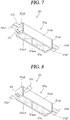
- FIGS. 7 through 9 are exploded perspective views illustrating examples in which the formation positions of an outlet 171c', 171c" and an inlet 171d', 171d" are modified in the heating unit 171 illustrated in FIG. 4 .
- the modified example is merely different from the foregoing embodiment in only the formation positions of the outlet 171c', 171c" and/or inlet 171d', 171d", and the configurations of the foregoing embodiment may be applied in a similar manner to other configurations.
- an inlet and an outlet of a heating unit 271 may be formed on a first and a second cover 271a2, 271a3, respectively.
- a first and a second outlet of the heating unit 271 may be formed together on the first cover 271a2, and a first and a second entrance portion 272c', 272c" connected to the first and the second outlet, respectively, may be disposed in parallel.
- the first and the second inlet of the heating unit 271 may be formed together on the second cover 271a3, and a first and a second return portion 272d', 272d" connected to the first and the second inlet, respectively, may be disposed in parallel.
- the outlet and inlet of the heating unit 271 may be formed on both lateral surfaces of a main case 271a1, and formed on the first and the second cover 271a2, 271a3.
- a combination of the foregoing structures is also possible.
- an outlet of a heating unit 371 may be formed on a main case 371a1, and an inlet of the heating unit 371 may be formed on a second cover 371a1.
- a first and a second outlet of the heating unit 371 may be formed on both lateral surfaces of the main case 371a1 to face each other.
- a first and a second inlet of the heating unit 371 may be formed together, and a first and a second return portion 372d', 372d"connected to the first and the second inlet, respectively, may be disposed in parallel.
- an outlet of a heating unit 471 may be formed on a main case 471a1.
- a first and a second inlet of the heating unit 471 may be formed together on a second cover 471a3, and a first and a second entrance portion 472c', 472" connected to the first and the second outlet, respectively, may be disposed in parallel.
- a first and a second outlet of the heating unit 471 may be formed on both lateral surfaces of the main case 471a1 to face each other.
- FIGS. 10 and 11 are conceptual views for explaining the circulation of working fluid (F) in a state prior to or subsequent to the operation of the heater 171b.
- working fluid (F) is present in a liquid phase, and filled up to a preset column of the top based on the lowest column of the heat pipe 172.
- the working fluid (F) in this state may be filled up to the lower two columns of the heat pipe 172.
- working fluid (F) within the heater case 171a is heated by the heater 171b.
- working fluid heated in a high-temperature gas phase (F1) is introduced into the entrance portion 172c', 172c" of the heat pipe 172 to dissipate heat to the cooling tube 131 while flowing through the heat pipe 172.
- the working fluid (F) flows in a phase (F2) that liquid and gas coexist while losing heat during the heat dissipation process, and is finally introduced into the heating unit 171 through the return portion 172d', 172d" of the heat pipe 172 in a liquid phase (F3).
- the working fluid (F) introduced into the heating unit 171 is heated again by the heater 171b to repeat (circulate) the foregoing flow, and transfer heat to the evaporator 130 during the process, thereby removing frost formed on the evaporator 130.
- working fluid (F) flows by a pressure difference generated by the heating unit 171 to quickly circulate the heat pipe 172, and thus the entire section of the heat pipe 172 may reach a stable operating temperature within a short period of time, thereby quickly carrying out defrosting.
- working fluid (F) introduced into the entrance portion 172c', 172c" is in a high-temperature gas phase (F1) and has the highest temperature during the circulation process of the heat pipe 172. Accordingly, the convection of heat due to working fluid (F) in such a high-temperature gas phase (F1) may be used to more efficiently remove frost formed on the evaporator 130.
- the entrance portion 172c', 172c" may be disposed at a relatively lower position than that of the lowest column of the cooling tube 131 provided in the evaporator 130 or at the same position as that of the lowest column. Accordingly, high-temperature working fluid (F) introduced through the entrance portion 172c', 172c" may transfer heat in the vicinity of the lowest column of the cooling tube 131 as well as such heat is increased and transferred to the cooling tube 131 adjacent to the lowest column.
- F high-temperature working fluid
- the temperature of the heating unit 171 rapidly increases according to the passage of time when working fluid (F) less than 30% compared to the entire internal volume of the heat pipe 172 and heater case 171a is filled. It denotes that working fluid (F) is insufficient compared to the entire internal volume of the heat pipe 172 and heater case 171a.
- the temperature of partial heat of the heat pipe 172 does not reach a stable operating temperature (less than 50° (freezing condition)) when working fluid (F) greater than 40% compared to the entire internal volume of the heat pipe 172 and heater case 171a is filled.
- a stable operating temperature less than 50° (freezing condition)
- working fluid (F) greater than 40% compared to the entire internal volume of the heat pipe 172 and heater case 171a is filled.
- Such a temperature decrease will be apparent as the heat pipe 172 is located closer to the return portion 172d', 172d".
- working fluid (F) compared to the entire internal volume of the heat pipe 172 and heater case 171a is excessive to increase a section in which working fluid (F) flows in a liquid phase.
- the temperature of the heating unit 171 and the temperature of each column of the heat pipe 172 reaches a stable operating temperature according to the passage of time when working fluid (F) greater than 30% but less than 40% compared to the entire internal volume of the heat pipe 172 and heater case 171a is filled.
- each column of the heat pipe 172 exhibits higher temperature as closer to the entrance portion 172c', 172c", and exhibits lower temperature as closer to the return portion 172d', 172d".
- an amount of filled working fluid (F) decreases, a difference between the temperature
- working fluid (F) greater than 30% but less than 40% compared to the entire internal volume of the heat pipe 172 and heater case 171a may be filled, but an optimized filling amount of working fluid (F) may be chosen for each defrosting device 170.
- FIG. 12 is a cross-sectional view in which another example 571 of the heating unit 171 illustrated in FIG. 3 is taken along a width direction.
- an outer fin 571a1c for the heat dissipation of the heater case is protruded and formed on an outer surface of the heater case.
- the outer fin 571a1c may be integrally formed on the heater case as a protruded configuration during the fabrication of the heater case (for example, extrusion molding of aluminum) or attached to the heater case by welding, an adhesive or the like as an additional configuration.
- a significant amount of heat generated from a heater 571b may be transferred to the heater case at a front side (in an upward direction of the present drawing) of the heater 571b [heat transfer to a rear side of the heater 571b relatively decreases), thereby preventing the overheating of the heater 571b. Furthermore, a rear temperature of the heater 571b is reduced to enhance the reliability and lifespan of the heater 571b. Moreover, heat transfer to a sealing member 571e provided at a rear side of the heater 571b decreases to prevent the melting of the sealing member 571e.
- the outer fin 571a1c may be formed on an upper surface of a main case 571a1.
- a plurality of outer fins 571a1c may be provided thereon, and extended and formed along a length or width direction of the main case 571a1 with a predetermined separation distance from each other. According to the present embodiment, it is seen that the outer fin 571a1c is extended and formed along a length direction of the main case 571a1.
- a separation distance between the plurality of outer fins 571a1c may be formed to be the same as a width of the outer fin 571a1c or to be larger than the width of the outer fin 571a1c. It is because a heat dissipation effect due to the outer fin 571a1c is not so large compared to a structure in which the outer fin 571a1c is not formed when the separation distance between the plurality of outer fins 571a1c is smaller than the width of the outer fin 571a1c.
- a significant amount of heat generated from the heater 571b is transferred to the main case 571a1 at a front side of the heater 571b by the outer fin 571a1c formed at an upper portion of the main case 571a1. Due to such heat transfer, it may be possible to prevent the overheating of the heater 571b as well as transfer a larger amount of heat to working fluid (F) within the main case 571a1 during the heat transfer process. In other words, the enhancement of heat transfer efficiency is accomplished.
- working fluid (F) when working fluid (F) is all in a liquid phase, it is configured such that the working fluid (F) is completely filled into a vacant space within the main case 571a1 to transfer the maximum amount of heat to the working fluid (F). It may be satisfied as described above in case where the heater case is provided at a lower portion of the evaporator 130, and working fluid (F) greater than 30% but less than 40% compared to the entire internal volume of the heat pipe and heater case is filled.
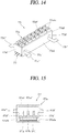
- FIGS. 13 and 14 are conceptual views illustrating examples in which the shape of outer fins 571a1c is modified in the heating unit 571 illustrated in FIG. 12 .
- an outer fin 671a1c may be formed on an upper surface of a main case 671a1 as well as another outer surface thereof.
- the outer fin 671a1c may be protruded and formed on both outer surfaces of the main case 671a1, respectively.
- the outer fin 671a1c may be formed in an elongated manner between the outlet 671c', 671c" and the inlet 671d', 671d".
- the outer fin 671a1c may be also protruded and formed on an outer surface of at least one of a first and a second cover 671a2, 671a3.
- the outer fin 671a1c when the outer fin 671a1c is formed on a cover corresponding to one of the outlet 671c', 671c" and inlet 671d', 671d" of the heating unit 671, the outer fin 671a1c may be protruded and formed on an outer surface of at least one cover on which the outlet 671c', 671c" and inlet 671d', 671d" are not formed between the first and the second cover 671a2, 671a3.
- an outer fin 771a1c may be protruded and formed in a protrusion shape on an outer surface of a heater case 771a.
- a plurality of outer fins 771a1c are provided, and disposed along a length and a width direction of a main case 771a1 with a predetermined separation distance from each other. Accordingly, the plurality of outer fins 771a1c may be disposed to form a matrix.
- a plurality of outer fins 771a1c are provided to have a protruded shape on an outer surface of the main case 771a1.
- an outer area of the heater case due to outer fins may be further increased.
- first and second extension fins are also protruded and formed on the heater case, they may be understood as a type of outer fins. Accordingly, the above-mentioned effect may be also accomplished by the first and the second extension fins.
- FIGS. 15 and 16 are cross-sectional views in which still another example 871 of the heating unit 171 illustrated in FIG. 3 is taken along a width and a length direction.
- an inner fin 871af1 for enhancing the heat transfer performance of a heater 871b is protruded and formed within the heater case.
- the inner fin 871af1 may be integrally formed on the heater case as a protruded configuration during the fabrication of the heater case (for example, extrusion molding of aluminum) or attached to the heater case by welding, an adhesive or the like as an additional configuration.
- a contact area to working fluid (F) filled into the heater case may increase, thereby increasing a heat transfer rate of being transferred from the heater 871b to working fluid (F).
- the entire volume of the heater case may increase to increase heat capacity capable of receiving heat from the heater case, thereby receiving more heat generated from the heater 871b. As a result, it may be possible to enhance defrosting performance.
- a significant amount of heat generated from a heater 871b may be transferred to the heater case at a front side (in an upward direction of the present drawing) of the heater 871b [heat transfer to a rear side of the heater 871b relatively decreases), thereby preventing the overheating of the heater 871b. Furthermore, a rear temperature of the heater 871b is reduced to enhance the reliability and lifespan of the heater 871b. Moreover, heat transfer to a sealing member 871e provided at a rear side of the heater 871b decreases to prevent the melting of the sealing member 871e.
- the inner fin 871af1 is protruded and formed on an inner surface at an inner side of an outer surface to which the heater 871b is attached on the main case 871a1. According to the present drawing, it is seen that the heater 871b is attached to an outer bottom surface of the main case 871a1, and the inner fin 871af1 is protruded and formed on an inner bottom surface of the main case 871a1.
- the inner fin 871af1 is preferably protruded and formed at a length less than 1/2 compared to an inner height of the main case 871a1.
- the inner fin 871af1 is protruded and formed at a length larger than 1/2 compared to an inner height of the main case 871a1, it may prevent working fluid (F) from efficiently flowing.
- a plurality of inner fins 871afl may be provided, and extended and formed along a length or width direction of the main case 871a1 with a predetermined separation distance from each other. According to the present embodiment, it is seen that the inner fin 871af1 is extended and formed along a length direction of the main case 871a1. In case of having a structure in which the inner fin 871af1 is integrally formed with the main case 871a1 by the extrusion molding of the main case 871a1, it has a structure in which the inner fin 871af1 is extended and formed along a length direction of the main case 871a1.
- a separation distance between each other of the plurality of inner fins 871af1 is preferably set to be above one time compared to a width of the inner fin 871af1. It is because flowing between the plurality of inner fins 871af1 is significantly reduced when the separation distance between each other of the plurality of inner fins 871af1 is less than the width of the inner fin 871af1.
- a separation distance between each other of the plurality of inner fins 871af1 may be preferably set to be less than two times compared to the width of the width of the inner fin 871af1 such that a lot of inner fins 871af1 are provided within the main case 871a1 to obtain an effect due to the formation of the inner fin 871af1 at a satisfactory level.
- a distance from an inner wall of the main case 871a1 and the inner fin 871af1 adjacent to the inner wall may be also preferably set to be greater than one time but less than two times compared to the width of the inner fin 871af1.
- working fluid (F) when working fluid (F) is all in a liquid phase, it is configured such that the working fluid (F) is completely filled into a vacant space within the main case 571a1 to transfer the maximum amount of heat to the working fluid (F). It may be satisfied as described above in case where the heater case is provided at a lower portion of the evaporator 130, and working fluid (F) greater than 30% but less than 40% compared to the entire internal volume of the heat pipe and heater case is filled.
- FIG. 17 is a cross-sectional view illustrating an example in which the formation positions of inner fins 971a1 are modified in the heating unit 971 illustrated in FIG. 16 .
- the inner fin 871af1 is extended and formed along a length direction of the main case 871a1 from one end of the main case 871a1 up to the other end thereof.
- FIG. 16 in a structure in which an outlet 871c" (an outlet at an opposite side is not shown) and an inlet 871d" (an inlet at an opposite side is not shown) are formed at positions separated from each other, respectively, with a predetermined distance along a length direction of the main case 871a1 on both lateral surfaces of the main case 871a1, the inner fin 871af1 is protruded and formed up to a height at which the inlet 871d" and outlet 871c" are formed. Accordingly, as illustrated in FIG. 16 , the inner fin 871af1 is disposed to cover part of the outlet 871c" and inlet 871d" with a separation distance along a width direction of the main case 871a1.
- the structure does not have a large effect on working fluid (F) discharged from the outlet 871c" and collected through the inlet 871d” but have some effect thereon in actuality when the inner fin 871af1 is protruded and formed at a length less than 1/2 compared to an inner height of the main case 871a1, and a distance between an inner wall of the main case 871a1 and the inner fin 871af1 adjacent to the inner wall is formed to be greater than one time compared to a width of the inner fin 871af1.
- an inner fin 971alf protruded and formed from an inner bottom surface of a main case 971a1 is formed between an inlet 971d" (an inlet at an opposite side is not shown) and an outlet 971c" (an outlet at an opposite side is not shown). According to the above-mentioned structure, the inner fin 971alf does not cover the outlet 971c" and inlet 971d" of the main case 971a1 along a width direction of the main case 971a1.
- working fluid (F) may be efficiently collected through the inlet 971d", and the collected working fluid (F) receive more heat due to the inner fin 971alf when heated again by the heater 971b while flowing forward, and the reheated working fluid (F) may be efficiently discharged through the outlet 971c".
- FIG. 18 is a cross-sectional view illustrating yet still another example 1071 of the heating unit 171 illustrated in FIG. 3 .
- a structure illustrated in FIG. 18 may be understood in combination of structures associated with the foregoing outer fins and inner fins.
- an outer fin 1071a1c for the heat dissipation of a main case 1071a1 is protruded and formed on an outer surface of the main case 1071a1
- an inner fin 1071a1f for the heat transfer performance enhancement of a heater 1071b is protruded and formed within the main case 1071a1.
- the heater 171b when the heater 171b is driven, the removal of frost formed on the evaporator 130 is started. Specifically, working fluid (F) is heated by the heater 171b to flow through the heat pipe 172, and heat dissipation is carried out on the cooling tube 131 of the evaporator 130 during the process to melt frost or ice formed on the cooling tube 131.
- the frost or ice is converted into water, namely, defrost water, due to defrosting, and falls onto the bottom of the evaporator 130, and according to circumstances, defrost water may fall even on the heating unit 171 provided at a lower portion of the evaporator 130.
- the hot wire 171b2 and terminal 171b3 of the heater 171b, and the lead wire 173 connected to the terminal 171b3 are configured to include a conductor, and thus there is a possibility of causing a short circuit when brought into contact with defrost water.
- the heater 171b may be possible to prevent a contact between the heater 171b and defrost water at a predetermined level according to a structure in which the heater 171b is attached to a bottom surface of the heater case 171a, a structure in which the sealing member 171e is disposed to cover the heater 171b, and a structure in which the first and the second extension fin 171ala, 171alb are protruded and formed at both sides of the heater case 171a to accommodate the heater 171b.
- the lead wire 173 has a shape of being exposed and extended to an outside of the heater case 171a. Due to such configuration characteristics, when defrost water flowed down to the lead wire 173 is cooled subsequent to defrosting and converted into frost or ice, the resultant weight increase may have an effect on contact with the terminal 171b3 or part of defrost water may flow to the side of the heater 171b or power along the lead wire 173 to cause a short circuit.
- the heating unit 171 is disposed in a shape of being extended along a left-right direction at a bottom portion of one side of the evaporator 130.
- the heating unit 171 may be disposed in a shape of being extended along a left-right direction of the evaporator 130 at the same height as that of the lowest column of the cooling tube 131 or a position lower than that of the lowest column of the cooling tube 131.
- the lead wire 173 connected between the heater 171b and the power is extended from one end portion of the heater 171b adjacent to an outer side of the evaporator 130 to an outer side.
- the lead wire 173 is extended to an outer side other than an inner side of the evaporator 130 and connected to the power.
- an area in which the lead wire 173 is disposed to a lower side of the evaporator 130 may be minimized, thereby minimizing defrost water from falling onto the lead wire 173.
- FIG. 19 illustrates a view in which the heating unit 171 is disposed at a left bottom portion of the evaporator 130.
- the lead wire 173 is extended from a left end portion of the heater 171b adjacent to the left side of the evaporator 130 to an outer side.
- the terminal 171b3 connected to the lead wire 173 may be preferably located at a left end portion of the heater 171b.
- FIG. 20 illustrates a view in which the heating unit 171 is disposed at a right bottom portion of the evaporator 130.
- the lead wire 173 is extended from a right end portion of the heater 171b adjacent to the right side of the evaporator 130 to an outer side.
- the terminal 171b3 connected to the lead wire 173 may be preferably located between the inlet and the outlet adjacent to the inlet of the heater case 171a.
- the right end portion of the heater 171b may be preferably disposed between the inlet and the outlet of the heater case 171a to disallow working fluid (F) collected through the inlet located at the right end portion of the heater case 171a from being reheated to flow backward.
- the hot wire 171b2 is not disposed at the inlet of the heater case 171a, and thus the inlet is located within the passive heating part (PHP).
- the return portion 172d', 172d" connected to the inlet of the heater case 171a is formed in a bent shape
- the direction of the returned working fluid (F) is switched at least once just prior to being introduced into the heater case 171a.
- a large flow resistance is formed at a bent portion, thereby preventing the returned working fluid (F) from being flowing backward.
- the foregoing examples illustrate a case where the heater case 171a is disposed horizontally to the evaporator, but the present disclosure may not be necessarily limited to this.
- the heater case 171a may be disposed in such a manner that an inlet-side end portion is disposed within an angle range greater than -90° but less than 2° with respect to an outlet-side end portion. It will be described in detail later.
- FIGS. 21A through 21C are graphs illustrating a temperature change of the heater 171b for an inner diameter of a return portion 172d', 172d" illustrated in FIG. 4 in a freezing condition
- FIG. 22 is a view conceptually illustrating the flow of fluid at the return portion 172d', 172d" in the condition of FIG. 21C .
- FIG. 21A is a view illustrating a case where an inner diameter of the return portion 172d', 172d" is 4.75 mm
- FIG. 21B is a view illustrating a case where the inner diameter of the return portion 172d', 172d" is 6.35 mm
- FIG. 21C is a view illustrating a case where the inner diameter of the return portion 172d', 172d" is 7.92 mm.
- an appropriate amount of working fluid (F) was set to 55g, 60g and 65g, respectively, to measure a temperature change of the heater 171b for an inner diameter of the return portion 172d', 172d".
- the overheating of the heater 171b occurred when the amount of working fluid (F) is 55g. It is regarded that an amount of working fluid (F) returned to the heater case 171a is reduced compared to an appropriate amount due to a small diameter of the return portion 172d', 172d", and not sufficiently brought into contact with the heater 171b for heating the working fluid (F).
- the diameter of the return portion 172d', 172d" is less than 5 mm as described above, it may cause a problem of overheating the heater 171b.
- the overheating of the heater 171b occurred when the amount of working fluid (F) is 55g, 65g.
- the diameter of the return portion 172d', 172d" is greater than 7 mm, it occurred a phenomenon in which the collected working fluid (Fa) is all filled into the return portion 172d', 172d", and not collected into the heater case 171a, and flowed to a space formed at an upper portion within the return portion 172d', 172d" and introduced into the heater case 171a.
- working fluid (Fa) introduced into the heater case 171a is heated again by the heater 171b to strongly flow within the heating unit 171, and part of the heated working fluid (Fb) is discharged to an upper space within the return portion 172d', 172d", and as a result, it occurs a phenomenon in which part of the heated working fluid (Fb) flows backward.
- the foregoing phenomenon occurs as an inner diameter of the return portion 172d', 172d" varies. Accordingly, in order to prevent the overheating of the heater 171b and the backflow of working fluid (F), the inlet 171d', 171d” should be formed within the passive heating part (PHP) as well as the return portion 172d', 172d" should have an appropriate inner diameter.
- PHP passive heating part
- an inner diameter of the return portion 172d', 172d" may be formed to be greater than 5 mm but less than 7 mm.
- a commercial tube having an inner diameter of 6.35 mm within the above range may be used for the return portion 172d', 172d".
- the heater case 171a having a specification with a width direction cross-section of 8 mm (height) x 13 mm (width) was used for the foregoing experiment.
- the specification of the heater case 171a may be slightly different from the specification used for the foregoing experiment, the return portion 172d', 172d" having the above inner diameter condition may be used in a similar manner for the return portion 172d', 172d".
- working fluid (F) heated and evaporated by the heater 171b within the heater case 171a is introduced into the entrance portion 172c', 172c" of the heat pipe 172, and working fluid (F) cooled while flowing through the heat pipe 172 is collected into the heater case 171a through the return portion 172d', 172d" of the heat pipe 172.
- an installation angle fo the heater case 171a with respect to the heat pipe 172 performs a key role on whether or not working fluid (F) circulates.
- FIG. 23 is graphs illustrating a temperature change of each column of the heater case 171a and heat pipe 172 according to an angle at which an inlet 171d', 171d" side end portion of the heater case 171a is inclined with respect to an outlet 171c', 171c" side end portion thereof.
- TH indicates a temperature of the heater case 171a
- TL indicates a temperature of the lowest column of the heat emitting part 172b of the heat pipe 172. Since working fluid (F) is heated by the heater 171b and circulated through the heat pipe 172, and then returned to the heater case 171a, the temperature (TH) of the heater case 171a is the highest, but the temperature (TL) of the lowest column of the heat emitting part 172b is the lowest. Accordingly, it is understood that the temperature of the remaining columns of the heat pipe 172 is between TH and TL.
- FIG. 23 for the sake of convenience of explanation, only temperature curves corresponding to TH and TL are shown with indication lines.
- whether or not working fluid (F) efficiently circulates may vary according to an angle at which an inlet 171d', 171d" side end portion of the heater case 171a is inclined with respect to an outlet 171c', 171c" side end portion thereof.
- the inlet 171d', 171d" and outlet 171c', 171c" are formed at both sides thereof, respectively, it relates to an angle at which an inlet 171d', 171d" side end portion of the heater case 171a is inclined with respect to an outlet 171c', 171c" side end portion thereof.
- the angle 0° denotes a configuration in which the heater case 171a is disposed horizontally to the evaporator 130
- a positive (+) angle denotes a configuration in which an inlet 171d', 171d" side end portion of the heater case 171a is inclined upward with respect to an outlet 171c', 171c" side end portion thereof
- a negative (-) angle denotes a configuration in which an inlet 171d', 171d" side end portion of the heater case 171a is inclined downward with respect to an outlet 171c', 171c" side end portion thereof.
- FIGS. 23D and 23F when an inlet 171d', 171d" side end portion of the heater case 171a is inclined upward with respect to an outlet 171c', 171c" side end portion thereof (when the outlet 171c', 171c" side is formed at a lower position than that of the inlet 171d', 171d” side), it is shown that the temperature of each column of the heater case 171a and heat pipe 172 has a large difference for each angle.
- an inlet 171d', 171d" side end portion of the heater case 171a may be preferably disposed to have an angle range greater than -90° but less than 2° with respect to an outlet 171c', 171c" side end portion thereof.
- FIGS. 24 through 26 are longitudinal cross-sectional views illustrating a modified example of a connection structure between the heating unit 171 and the heat pipe 172 in the heating unit 171 applied to FIGS. 19 and 20 .
- the present drawings briefly illustrate a heating unit 1171, 1271, 1371 with only a heater case 1171a, 1271a, 1371a and a heater 1171b, 1271b, 1371b for the sake of convenience of explanation.
- the foregoing detailed structure (a structure formed with first and second extension fins, a sealing member, outer fins, inner fins, and the like) may be of course applicable to the heating unit 1171, 1271, 1371.
- the present disclosure will be describes based on that the heater case 1171a, 1271a, 1371a is disposed horizontally to the evaporator, but the present disclosure may not be necessarily limited to this.
- the heater case 1171a, 1271a, 1371a may be disposed such that an inlet 1171d", 1271d", 1371d" (an inlet at an opposite side is not shown) side end portion has an angle range greater than -90° but less than 2° with respect to an outlet 1271c", 1271c", 1371c" (an outlet at an opposite side is not shown).
- the present disclosure will be described based on that the inlet 1171d", 1271d", 1371d” and outlet 1271c", 1271c", 1371c” are formed at positions separated by a predetermined distance along a length direction at both lateral surfaces of the heater case 1171a, 1271a, 1371a (a structure illustrated in the above FIG. 4 ), but the present disclosure may not be necessarily limited to this. At least one of the inlet 1171d", 1271d", 1371d” and outlet 1271c", 1271c", 1371c" of the heating unit 1171, 1271, 1371 may be formed at an end portion of the heater case 1171a, 1271a, 1371a (a structure illustrated in the above FIGS. 7 through 9 ).
- working fluid (F) is collected through the inlet 1171d", 1271d", 1371d” and then heated again by the heater 1171b, 1271b, 1371b and discharged to the outlet 1271c", 1271c", 1371c".
- a return portion 1172d", 1272d", 1372d” of the heat pipe (an opposite side is not shown) may be disposed in parallel to the heater case 1171a, 1271a, 1371a or extended and formed (or extended downward and bent to be horizontally extended and formed) in a downward direction of the heater case 1171a, 1271a, 1371a
- an entrance portion 1172c", 1272c", 1372c" of the heat pipe (an opposite side is not shown) may be disposed in parallel to the heater case 1171a, 1271a, 1371a or extended and formed in an upward direction of the heater case 1171a, 1271a, 1371a.
- the meaning of being extended and formed in an upward and/or downward direction may include being extended and formed in a vertical manner as well as being extended and formed in an inclined manner.
- both the return portion 1172d", 1272d", 1372d” and entrance portion 1172c", 1272c", 1372c” may be extended and formed along a length direction of the heater case 1171a, 1271a, 1371a, but in the aspect of flow design in consideration of a rising force of working fluid (F), only either one of the return portion 1172d", 1272d", 1372d” and entrance portion 1172c", 1272c", 1372c” may be preferably extended and formed along a length direction of the heater case 171a.
- FIG. 24 illustrates a view in which the return portion 1172d" of the heat pipe is extended and formed along a length direction of the heater case 1171a, and the entrance portion 1172c" of the heat pipe is extended and formed in an upward direction of the heater case 1171a.
- FIG. 25 illustrates a view in which the return portion 1272d" of the heat pipe is extended and formed in a downward direction of the heater case 1271a, and the entrance portion 1272c', 1272c" of the heat pipe is extended and formed in an upward direction of the heater case 1271a.
- the foregoing two examples may be applicable to a structure in which the heating unit 171 is directly connected to a vertical extension portion of the heat pipe 172 as illustrated in FIG. 19 in the aspect that the entrance portion 1172c", 1272c" of the heat pipe is extended and formed in an upward direction of the evaporator.
- a lower end portion of the vertical extension portion constitutes the entrance portion 1172c", 1272c".
- the foregoing two examples are configured such that the a terminal (not shown) of the heater 1171b, 1271b is formed adjacent to an outlet 1271c", 1271c" of the heater case 1171a, 1271a, and a lead wire 1173, 1273 is connected to the terminal and extended to an outside.
- the structure illustrated in FIG. 25 is a structure in which working fluid (F) heated to have a rising force is unable to flow backward to the return portion 1272d" as the return portion 1272d" of the heat pipe 1272 has a structure of being extended and formed at a downward direction of the heater case 1271a. Accordingly, it may be possible to form a more natural flow of discharging the heated working fluid (F) through the entrance portion 1272c" without flowing backward to the return portion 1272d".
- FIG. 26 it is shown that the return portion 1372d" of the heat pipe 1372 is extended and formed in a downward direction of the heater case 1371a, and the entrance portion 1372c" of the heat pipe 1372 is extended and formed along a length direction of the heater case 1371a.
- the foregoing structure may be applicable to a structure in which the heating unit 171 is directly connected to a horizontal extension portion of the heat pipe 172 as illustrated in FIG. 20 in the aspect that the entrance portion 1372c" of the heat pipe 1372 is extended and formed along a length direction of the heater case 1371a.
- an end portion of the horizontal extension portion constitutes the entrance portion 1372".
- it is configured such that a terminal (not shown) of the heater 1371b is formed between the inlet 1371d" and the outlet 1371c" of the heater case 1371a, and the led wire 1373 is connected to the terminal and extended to an outside.
- the heater case 1471a may be extended and formed in a vertical direction from a lower side of the evaporator 1430 to an upper side thereof such that an inlet 1471d" (an inlet at an opposite side is not shown) side end portion forms an angle of -90° with respect to an outlet 1471c" (an outlet at an opposite side is not shown) side end portion.
- FIGS. 27 and 28 are a front view and a perspective view illustrating a second embodiment 1470 of the defrosting device 170 applied to the refrigerator 100 in FIG. 1 .
- a heating unit 1471 may be disposed at one outer side of a defrosting device 1470.
- a heater case 1471a may be located at an outer side of a support fixture 1433 provided at one side of an evaporator 1430, and extended and formed in a vertical direction from a lower side of the evaporator 1430 to an upper side thereof.
- at least part of the heater case 1471a may be disposed between a first cooling tube 1431' and a second cooling tube 1431"
- the heater case 1471a is connected to heat pipes 1472, respectively, to form a passage capable of circulating working fluid (F).
- An outlet 1471c" and an inlet 1471d" are formed at an upper and a lower side of the heater case 1471a, respectively.
- the outlet 1471c" is connected to an extension portion of the heat pipe 1472, and the inlet 1471d" is connected to the lowest column of the heat pipe 1472.
- a heater 1471b is configured with a plate-shaped heater 1471b extended and formed along one direction, and attached to an outer surface of the heater case 1471a and vertically disposed in a top-down direction of the evaporator 1430.
- FIG. 27 briefly illustrates the heater case 1471a with only the heater case 1471a and heater 1471b for the sake of convenience of explanation.
- the foregoing detailed structure (a structure formed with first and second extension fins, a sealing member, outer fins, inner fins, and the like) may be of course applicable to the heating unit 1471.
- the heater 1471b is attached to one surface of the heater case 1471a facing outward. According to the layout, it may be possible to prevent defrost water from being brought into contact with the heater 1471b at a predetermined level. However, the present disclosure may not be necessarily limited to this.
- the heater 1471b may be also attached to another surface of the heater case 1471a facing the support fixture 133. However, in this case, a structure capable of preventing contact between the heater 1471b and defrost water may be preferably provided.
- an outer fin may be protruded and formed on another surface of the heater case 1471a facing the support fixture 133, and an inner fin may be protruded and formed on an inner surface of an inner side of one surface to which the heater 1471b is attached.
- a hot wire 1471b2 of the heater 1471b is extended and formed between the inlet 1471d" and the outlet 1471c" toward the outlet 1471c", and configured to reheat working fluid (F) collected through the inlet 1471d".
- a terminal (not shown) of the heater 1471b may be formed at an end portion of the heater 1471b located between the inlet 1471d" and the outlet 1471c", and a lead wire 1473 is connected to the terminal and extended toward a lower side of the evaporator 1430.
- working fluid (F) may be preferably filled at a higher position than that of the highest end of the heater 1471b extended in a vertical direction within the heater case 1471a. According to the foregoing configuration, defrosting operation may be stably carried out in a state that the heating unit 1471 is not overheated, and the continuous supply of working fluid (F) in a gas phase to the heat pipe 1472 may be stably carried out.
- FIG. 29 is a conceptual view illustrating a third embodiment 1570 in which a width between upper columns and lower columns of the heat pipe 1572 is differently formed in the defrosting device 170 applied to the refrigerator 100 in FIG. 1 .
- the defrosting device 1570 is shown on a front surface (a) and a lateral surface (b) thereof.
- FIG. 29A illustrates a configuration that a first cooling tube 1531' at a front side is omitted to exhibit the entire shape of the heat pipe 1572. Furthermore, part of a second cooling tube 1531" may not be seen due to overlapping with the heat pipe 1572, but referring to the layout of a cooling fin 1532 and FIG. 29B , the entire shape of the first and the second cooling fin 1531', 1521" may be seen.
- the cooling tube 1531 and heat pipe 1572 are repeated bent in a zigzag shape to form a plurality of columns.
- the cooling tube 1531 may be configured with a combination of horizontal pipe portions and bending pipe portions.
- the horizontal pipe portions are horizontally disposed in a top-down direction, and configured to pass through cooling fins 1532, and the bending pipe portions are connected between an end portion of an upper horizontal pipe portion and an end portion of a lower horizontal pipe portion to communicate with each other.
- each column of the horizontal pipe portions may be disposed at predetermined intervals as illustrated in the drawing.
- the heat pipe 1572 is disposed between a first cooling tube 1531' and a second cooling tube 1531" to form a single row.
- the heat pipe 1572 may include an extension portion 1572a and a heat emitting part 1572b. The description of the extension portion 1572a will be substituted by the description of previous embodiment.
- the heat emitting part 172b is extended in a zigzag shape along the cooling tube 1531 of the evaporator 1530 from the extension portion 1572a connected to an inlet of the heating unit 1571.
- the heat emitting part 1572b is configured in combination with a plurality of horizontal tubes 1572b' constituting columns and a connecting tube 1572b" formed in a bent U-shaped tube to connect them in a zigzag shape.
- a distance between each column of the horizontal tubes 1572b' at a lower portion thereof may be formed to be smaller than that of horizontal tubes 1572b' at an upper portion thereof. It is a design in consideration of convection according to a temperature of working fluid (F) when the working fluid (F) circulates the heat pipe 1572.
- working fluid (F) introduced through the entrance portion of the heat pipe 1572 is in a high-temperature gas phase, and has the highest temperature during the circulation process of the heat pipe 1572.
- high-temperature working fluid (F) moves toward the cooling tube 1531, and thus high-temperature heat is transferred to a large area by convection around the cooling tube 1531 at an upper portion thereof.
- working fluid (F) flows in a state that in a phase that liquid and gas coexist while gradually losing heat, and is finally introduced into the return portion, and the heat at this time is a sufficient temperature for removing frost on the cooling tube 1531, but an amount of heat transfer to the surrounding is smaller than the former case.
- each column of the heat pipe 1572 close to the return portion (namely, the horizontal tubes 1572b' of the heat emitting part 1572b) is disposed with a smaller distance compared to that of the heat pipe 1572 located at an upper portion thereof.
- each column of the heat pipe 1572 located at an upper portion thereof may be disposed to correspond to a column of the adjoining cooling tube 1531 by interposing one column of the cooling tube 1531 therebetween, and each column of the heat pipe 1572 located at a lower portion thereof may be disposed to correspond to each column of the cooling tube 1531.
- a lower portion of the evaporator 1530 is arranged with a relatively larger number of horizontal tubes 1572b' of the heat emitting part 1572b than that of an upper portion thereof.
- FIGS. 30 and 31 are conceptual views illustrating a modified example 1670 of the defrosting device 1570 illustrated in FIG. 29 .
- FIG. 30 illustrates a front surface (a) and a lateral surface (b) of the defrosting device 1670.
- a heat pipe 1672 may include a first heat pipe 1672' at a front side of a first cooling tube 1631' and a second heat pipe 1672" at a rear side of a second cooling tube 1631" to form two columns.
- the second heat pipe 1672" may not be seen due to overlapping with the first heat pipe 1672' in FIG. 30A , but referring to FIG. 30B , the entire shape of the second cooling fin 1672" may be seen.
- a distance between each column of the horizontal tubes 1672b' disposed at a lower portion of the first and the second heat pipe 1672', 1672" may be formed to be smaller than that between each column of the horizontal tubes 1672b' disposed at an upper portion thereof. It is a design in consideration of convection according to a temperature of working fluid (F) when the working fluid (F) circulates the heat pipe 1672, and the detailed description thereof will be substituted by the earlier description of FIG. 29 .
- FIG. 31 illustrates a view in which part of a first and a second cooling tube 1731', 1731" is omitted to help understanding.
- a distance between each column disposed at a lower portion of a first heat pipe 1772' at a front side of an evaporator 1730 may be formed to be smaller than that of each column disposed at an upper portion thereof.
- a distance between each column disposed at an upper portion of a first heat pipe 1772' at a rear side of the evaporator 1730 may be formed to be smaller than that of each column disposed at an lower portion thereof.
- a temperature decrease due to any one portion having a smaller distance of the heat pipe 1772 may be compensated by a temperature increase due to another portion having a smaller distance of the heat pipe 1772.
- the present disclosure may implement an efficient heat transfer structure to a cooling tube 1731 while the first and the second heat pipe 1772', 1772" are configured to be shorter than the basic structure (a structure illustrated in FIG. 3 ).
- a distance between each column disposed at a lower portion of the first heat pipe 1772' at a front side of the evaporator 1730 may be formed to be larger that between each column disposed at an upper portion thereof.
- a distance between each column disposed at an upper portion of the second heat pipe 1772" at a rear side of the evaporator 1730 may be formed to be larger that between each column disposed at a lower portion thereof.
- working fluid (F) dissipates heat to a cooling tube 1831 while flowing a heat pipe 1872, the working fluid (F) is cooled when closer to an inlet of a heating unit 1871. Accordingly, defrosting for a lower cooling tube 1731 may not be efficiently carried out.
- a structure capable of solving this problem will be described.
- FIGS. 32 and 33 are a front view and a perspective view illustrating a fourth embodiment 1870 of the defrosting device 170 applied to the refrigerator 100 in FIG. 1 .
- FIG. 32 illustrates a view in which part of a cooling fin 1832 is omitted.
- the detailed configuration of an evaporator 1830 is illustrated in more detail in FIG. 33 .
- a heat pipe 1872 may be divided into a high-temperature evaporator (E) and a low-temperature condenser (C) in the aspect according to the phase of circulating working fluid (F).
- An evaporator (E) as a portion in which working fluid (F) moves in a phase containing a high-temperature gas or high-temperature gas and liquid has a temperature capable of removing frost on the cooling tube 1831.
- the evaporator (E) is connected to an outlet of a heating unit 1871, and disposed to correspond to the cooling tube 1831 of the evaporator 1830 to transfer heat to the cooling tube 1831 of the evaporator 1830.
- a condenser (C) as a portion in which working fluid (F) flows in a low-temperature liquid phase has a temperature lower than that capable of performing defrosting on the cooling tube 1831. Accordingly, even when the condenser (C) is disposed adjacent to the cooling tube 1831, defrosting on the cooling tube 1831 may not be efficiently carried out.
- the condenser (C) is finally connected to an inlet of the heating unit 1871.
- a heat pipe 1872 is extended in a zigzag shape from the top to the bottom, and thus when the heat pipe 1872 is arranged to correspond to the cooling tube 1831, the condenser (C) is disposed adjacent to a lower side of the cooling tube 1831. It denotes that defrosting on the lower cooling tube 1831 cannot be efficiently carried out.
- the condenser (C) is extended from the evaporator (E) and disposed lower than the lowest column cooling tube 1831a of the evaporator 1830.
- the condenser (C) is configured to including at least two horizontal tubes disposed lower than the lowest column cooling tube 1831a. According to the present embodiment, it is shown a structure in which two columns of the heat pipes 1872 are further provided lower than the lowest column of the cooling tube 1831 of the evaporator 1830 to constitute the condenser (C).
- the low-temperature condenser (C) of the heat pipe 1872 is disposed lower than the lowest column cooling tube 1831a of the evaporator 1830, only the high-temperature evaporator (E) may be used for defrosting of the evaporator 1830, and thus defrosting on a lower side of the cooling tube 1831 may be efficiently carried out.
- a lower end of the heating unit 1871 is disposed adjacent to the lowest column cooling tube 1831a. Accordingly, a return portion of the heat pipe 1872 is extended in an upward bent shape from the lowest column horizontal tube of the condenser (C) to an inlet of the heating unit 1871 to form a passage capable of collecting the condensed working fluid (F).
- a large flow resistance is formed at a portion having a bent shape on the return portion, and thus there is an advantage of suppressing working fluid (F) returned to an inlet of the heating unit 1871 from flowing backward.
- FIGS. 34 and 35 are a front view and a perspective view illustrating an example 1970 in which the formation position of the heating unit 1971 is modified in the defrosting device 1870 illustrated in FIGS. 32 and 33 .
- At least part of the heating unit 1971 is disposed lower than the lowest column cooling tube 1931 of an evaporator 1930.
- a lower end of the heating unit 1971 may be located adjacent to the lowest column horizontal tube of a heat pipe 1972, and an upper end of the heating unit 1971 may be located below the first cooling tube 1931b on the top (namely, second cooling tube on the bottom) from the lowest column cooling tube 1931a of the evaporator 1930.
- a return portion connected between the lowest column horizontal tube of the heat pipe 1972 and an inlet of the heating unit 1971 is formed to be shorter than the return portion of the previous embodiment.
- a return portion may be extended from the lowest column horizontal tube of the heat pipe 1972 in a horizontal direction and connected to the inlet of the heating unit 1971.
- the heating unit 1971 is disposed adjacent to the lowest column horizontal tube of the heat pipe 1972, and thus a heater 1971b is located below a water level of working fluid (F) with a smaller amount of working fluid (F) compared to the previous embodiment.
- a temperature of the lowest column horizontal tube of the heat pipe 1972 may further increase as a filling amount of working fluid (F) decreases. It denotes that a lower temperature of the evaporator (E) increases compared to the previous examples.
Landscapes
- Engineering & Computer Science (AREA)
- Physics & Mathematics (AREA)
- Thermal Sciences (AREA)
- Mechanical Engineering (AREA)
- General Engineering & Computer Science (AREA)
- Chemical & Material Sciences (AREA)
- Combustion & Propulsion (AREA)
- Life Sciences & Earth Sciences (AREA)
- Sustainable Development (AREA)
- Geometry (AREA)
- Defrosting Systems (AREA)
- Resistance Heating (AREA)
Claims (14)
- Abtauvorrichtung (170), die Folgendes umfasst:eine Heizeinheit (171), die in einem Verdampfer (130) vorgesehen ist; undeine Heizleitung (172), wovon beide Endabschnitte jeweils mit einem Einlass (171d', 171d") und einem Auslass (171c', 171c") der Heizeinheit (171) verbunden sind und wobei wenigstens ein Teil der Heizleitung angrenzend an ein Kühlrohr (131) angeordnet ist, um Wärme an das Kühlrohr des Verdampfers durch ein Hochtemperatur-Arbeitsfluid (F) abzuführen, das durch die Heizeinheit (171) geheizt und übertragen wird,wobei die Heizeinheit (171) Folgendes umfasst:ein Heizelementgehäuse (171a), das mit einem leeren Raum versehen ist, und das mit dem Einlass und dem Auslass jeweils bei Positionen versehen ist, die entlang einer Längsrichtung voneinander getrennt sind; undein Heizelement (171b), das an einer äußeren Oberfläche des Heizelementgehäuses (171a) befestigt ist, um Arbeitsfluid (F) in dem Heizelementgehäuse (171a) zu heizen,dadurch gekennzeichnet, dass das Heizelement (171b) Folgendes umfasst:eine Basisplatte (171b1), die aus einem Keramikmaterial gebildet ist und an der äußeren Oberfläche des Heizelementgehäuses (171a) befestigt ist;einen Heizdraht (171b2), der an der Basisplatte (171b1) ausgebildet ist und konfiguriert ist, während des Anlegens einer Spannung Wärme zu verteilen; undeinen Anschluss (171b3), der an der Basisplatte (171b1) vorgesehen ist, um den Heizdraht (171b2) mit der Spannung elektrisch zu verbinden.
- Abtauvorrichtung nach Anspruch 1, wobei das Heizelementgehäuse (171a) in ein aktives Heizteil (AHP), das einem Abschnitt entspricht, bei dem der Heizdraht (171b2) angeordnet ist, und in ein passives Heizteil (PHP), das einem Abschnitt entspricht, bei dem der Heizdraht (171b2) nicht vorliegt, unterteilt ist,
und
wobei der Einlass (171d', 171d") auf dem passiven Heizteil (PHP) ausgebildet ist, um zu verhindern, dass Arbeitsfluid, das durch die Heizleitung (172) bewegt und dann durch den Einlass (171d', 171d") rückgeführt wird, um rückwärts zu strömen, erneut geheizt wird. - Abtauvorrichtung nach Anspruch 1 oder 2, wobei sich der Heizdraht (171b2) längs erstreckt und von einem Punkt zwischen dem Einlass (171d', 171d") und dem Auslass (171c', 171c") in Richtung des Auslasses ausgebildet ist.
- Abtauvorrichtung nach einem der Ansprüche 1 bis 3, wobei das Heizelement (171b) an einer Bodenfläche des Heizelementgehäuses (171a) befestigt ist.
- Abtauvorrichtung nach Anspruch 4, wobei eine erste und eine zweite Erweiterungslamelle (171a1a, 171a1b), die sich längs erstrecken und von der Bodenfläche des Heizelementgehäuses (171a) abwärts ausgebildet und konfiguriert sind, beide seitliche Oberflächen des Heizelements (171b), das an der Bodenfläche des Heizelementgehäuses (171a) befestigt ist, zu bedecken, jeweils an beiden Seiten des Heizelementgehäuses (171a) vorgesehen sind.
- Abtauvorrichtung nach Anspruch 5, wobei ein Dichtungselement (171e) eingefüllt ist, um das Heizelement (171b) an einer hinteren Oberfläche des Heizelements und einen ausgesparten Raum (R), der durch die erste und die zweite Erweiterungslamelle (171a1a, 171a1b) gebildet wird, zu bedecken, und wobei ein Isoliermaterial (171f) zwischen der hinteren Oberfläche des Heizelements (171b) und dem Dichtungselement (171e) angeordnet ist.
- Abtauvorrichtung nach Anspruch 5 oder 6, wobei das Heizelementgehäuse (171a) Folgendes umfasst:ein Hauptgehäuse (171a1), das mit einem leeren Raum versehen ist, wovon beide Endabschnitte eine offene Form haben, und wobei das Heizelement (171b) an einer Bodenfläche davon haftet; undeine erste Abdeckung (171a2) und eine zweite Abdeckung (171a2), die so angebracht sind, dass sie jeweils beide offene Endabschnitte des Hauptgehäuses (171a1) bedecken.
- Abtauvorrichtung nach einem der Ansprüche 1 bis 7, wobei eine äußere Lamelle (571a1c) vorsteht und an einer weiteren äußeren Oberfläche des Heizelementgehäuses (571a), die sich von der äußeren Oberfläche, an der das Heizelement (571b) haftet, unterscheidet, ausgebildet ist.
- Abtauvorrichtung nach Anspruch 8, wobei das Heizelement (571b) an einer Bodenfläche des Heizelementgehäuses (571a) befestigt ist und wobei die äußere Lamelle (571a1c) an einer oberen Oberfläche des Heizelementgehäuses (571a) ausgebildet ist.
- Abtauvorrichtung nach Anspruch 8 oder 9, wobei mehrere äußere Lamellen (571a1c) daran vorgesehen sind und sich längs erstrecken und entlang einer Längsrichtung oder Breitenrichtung des Heizelementgehäuses (571a) mit einem festgelegten Trennabstand voneinander ausgebildet sind, und
der Trennabstand so eingestellt ist, dass er so groß wie eine Breite der äußeren Lamelle (571a1c) oder größer ist. - Abtauvorrichtung nach einem der Ansprüche 1 bis 10, wobei eine innere Lamelle (871a1f) vorsteht und an einer inneren Oberfläche an einer Innenseite der äußeren Oberfläche ausgebildet ist.
- Abtauvorrichtung nach Anspruch 11, wobei das Heizelement (871b) an einer äußeren Bodenfläche des Heizelementgehäuses (871a) befestigt ist und
die innere Lamelle (871a1f) vorsteht und von einer inneren Bodenfläche des Heizelementgehäuses (871a) ausgebildet ist. - Abtauvorrichtung nach Anspruch 12, wobei die innere Lamelle (871a1f) vorsteht und mit einer Länge ausgebildet ist, die im Vergleich zu einer inneren Höhe des Heizelementgehäuses (871a) weniger als die Hälfte beträgt.
- Abtauvorrichtung nach Anspruch 12 oder 13, wobei mehrere innere Lamellen (871a1f) daran vorgesehen sind und sich längs erstrecken und mit einem festgelegten Trennabstand voneinander entlang einer Längsrichtung des Heizelementgehäuses (871a) ausgebildet sind, und
ein Abstand von einer Innenwand des Heizelementgehäuses (871a) zu der inneren Lamelle (871a1f) angrenzend an die Innenwand so ausgebildet ist, dass er im Vergleich größer als die einfache, jedoch kleiner als die doppelte Breite der inneren Lamelle (871a1f) ist, und
ein Trennabstand zwischen den mehreren inneren Lamellen (871a1f) so ausgebildet ist, dass er im Vergleich größer als die einfache, jedoch kleiner als die doppelte Breite der inneren Lamelle (871alf) ist.
Priority Applications (1)
| Application Number | Priority Date | Filing Date | Title |
|---|---|---|---|
| EP19211279.5A EP3708933A1 (de) | 2015-10-21 | 2016-08-01 | Abtauvorrichtung und kühlschrank damit |
Applications Claiming Priority (4)
| Application Number | Priority Date | Filing Date | Title |
|---|---|---|---|
| KR1020150147012A KR102447836B1 (ko) | 2015-10-21 | 2015-10-21 | 제상 장치 및 이를 구비하는 냉장고 |
| KR1020150147011A KR102447835B1 (ko) | 2015-10-21 | 2015-10-21 | 제상 장치 및 이를 구비하는 냉장고 |
| KR1020150147010A KR102447834B1 (ko) | 2015-10-21 | 2015-10-21 | 제상 장치 및 이를 구비하는 냉장고 |
| PCT/KR2016/008436 WO2017069386A1 (ko) | 2015-10-21 | 2016-08-01 | 제상 장치 및 이를 구비하는 냉장고 |
Related Child Applications (2)
| Application Number | Title | Priority Date | Filing Date |
|---|---|---|---|
| EP19211279.5A Division-Into EP3708933A1 (de) | 2015-10-21 | 2016-08-01 | Abtauvorrichtung und kühlschrank damit |
| EP19211279.5A Division EP3708933A1 (de) | 2015-10-21 | 2016-08-01 | Abtauvorrichtung und kühlschrank damit |
Publications (3)
| Publication Number | Publication Date |
|---|---|
| EP3367025A1 EP3367025A1 (de) | 2018-08-29 |
| EP3367025A4 EP3367025A4 (de) | 2019-05-22 |
| EP3367025B1 true EP3367025B1 (de) | 2020-03-11 |
Family
ID=58557608
Family Applications (2)
| Application Number | Title | Priority Date | Filing Date |
|---|---|---|---|
| EP19211279.5A Withdrawn EP3708933A1 (de) | 2015-10-21 | 2016-08-01 | Abtauvorrichtung und kühlschrank damit |
| EP16857644.5A Active EP3367025B1 (de) | 2015-10-21 | 2016-08-01 | Abtauvorrichtung und kühlschrank damit |
Family Applications Before (1)
| Application Number | Title | Priority Date | Filing Date |
|---|---|---|---|
| EP19211279.5A Withdrawn EP3708933A1 (de) | 2015-10-21 | 2016-08-01 | Abtauvorrichtung und kühlschrank damit |
Country Status (5)
| Country | Link |
|---|---|
| US (1) | US10520240B2 (de) |
| EP (2) | EP3708933A1 (de) |
| JP (1) | JP6484709B2 (de) |
| CN (1) | CN107003060B (de) |
| WO (1) | WO2017069386A1 (de) |
Families Citing this family (4)
| Publication number | Priority date | Publication date | Assignee | Title |
|---|---|---|---|---|
| CN108444169A (zh) * | 2018-04-02 | 2018-08-24 | 合肥美的电冰箱有限公司 | 排水器及冰箱 |
| US11492126B2 (en) * | 2019-07-31 | 2022-11-08 | B/E Aerospace, Inc. | Restricted space air chiller |
| CN112066769A (zh) * | 2020-09-17 | 2020-12-11 | 北京空间飞行器总体设计部 | 非均匀散热的冷凝器和环路热管 |
| JP7765956B2 (ja) * | 2021-12-09 | 2025-11-07 | シャープ株式会社 | 冷蔵庫 |
Family Cites Families (37)
| Publication number | Priority date | Publication date | Assignee | Title |
|---|---|---|---|---|
| US2635439A (en) * | 1950-08-09 | 1953-04-21 | Nash Kelvinator Corp | Refrigerant evaporating element |
| US2631442A (en) * | 1951-05-22 | 1953-03-17 | Bally Case And Cooler Company | Automatic defrosting system and assembly |
| US2781646A (en) * | 1953-12-11 | 1957-02-19 | Westinghouse Electric Corp | Evaporator defrosting arrangement |
| US3100969A (en) * | 1960-08-03 | 1963-08-20 | Thore M Elfving | Thermoelectric refrigeration |
| US4087987A (en) * | 1976-10-06 | 1978-05-09 | General Electric Company | Defrost pressure control system |
| US4492851A (en) * | 1980-12-29 | 1985-01-08 | Brazeway, Inc. | Swap action arrangement mounting an electric defroster heater to a finned refrigeration unit |
| US4649713A (en) * | 1984-05-21 | 1987-03-17 | Bezek Donald J | Microwave ice detector |
| JPS61240079A (ja) * | 1985-04-16 | 1986-10-25 | 松下冷機株式会社 | 冷凍機用蒸発器 |
| JPS6355762A (ja) | 1986-08-27 | 1988-03-10 | Canon Inc | カセツト装着装置 |
| US4716275A (en) * | 1986-11-13 | 1987-12-29 | Thermo King Corporation | Evaporator coil heat exchanger assembly |
| JPH0587475A (ja) * | 1991-09-27 | 1993-04-06 | Furukawa Electric Co Ltd:The | ヒートパイプ式冷却器 |
| JPH0783558A (ja) * | 1993-09-14 | 1995-03-28 | Sharp Corp | 除霜ヒータ |
| JPH08303932A (ja) * | 1995-05-08 | 1996-11-22 | Fuji Electric Co Ltd | 冷凍冷蔵ショーケースの除霜装置 |
| JPH08313144A (ja) * | 1995-05-17 | 1996-11-29 | Fuji Electric Co Ltd | 冷凍冷蔵ショーケースの除霜装置 |
| US5731568A (en) * | 1995-10-13 | 1998-03-24 | Arctic Fox, Inc. | Battery heating device and method |
| JP3362596B2 (ja) * | 1996-03-29 | 2003-01-07 | 富士電機株式会社 | 冷却器の除霜装置 |
| JP3223166B2 (ja) * | 1997-08-26 | 2001-10-29 | エルジー電子株式会社 | 冷蔵庫 |
| KR100469322B1 (ko) * | 2002-02-19 | 2005-02-02 | 삼성전자주식회사 | 증발기 |
| JP2003249334A (ja) * | 2002-02-27 | 2003-09-05 | Toshiba Ceramics Co Ltd | セラミックスヒーターの製造方法 |
| JP2003279220A (ja) * | 2002-03-20 | 2003-10-02 | Mitsubishi Electric Corp | 冷蔵庫 |
| US6755026B2 (en) * | 2002-10-24 | 2004-06-29 | Tech Medical Devices Inc. | Thermoelectric system to directly regulate the temperature of intravenous solutions and bodily fluids |
| KR100664051B1 (ko) * | 2003-04-08 | 2007-01-03 | 엘지전자 주식회사 | 열교환기의 제상장치 |
| JP4903988B2 (ja) | 2004-03-30 | 2012-03-28 | 泰和 楊 | 自然サーモキャリアの熱作動で対流する放熱システム |
| KR20090102298A (ko) * | 2008-03-26 | 2009-09-30 | 엘지전자 주식회사 | 조리기기 |
| CN102016462B (zh) | 2008-04-28 | 2013-07-10 | 阿莫绿色技术有限公司 | 利用条带形平板发热体的除霜加热器及其制造方法和除霜装置 |
| KR101037651B1 (ko) * | 2008-06-27 | 2011-05-30 | 주식회사 아모그린텍 | 제상용 면상 히터 |
| US8575518B2 (en) * | 2009-01-28 | 2013-11-05 | Gentherm Incorporated | Convective heater |
| US8237471B2 (en) * | 2009-11-25 | 2012-08-07 | International Business Machines Corporation | Circuit with stacked structure and use thereof |
| JP5616957B2 (ja) * | 2010-03-26 | 2014-10-29 | シチズンホールディングス株式会社 | 電波時計 |
| KR101125827B1 (ko) * | 2010-05-03 | 2012-03-27 | 김종수 | 버블젯을 이용한 루프형 히트파이프가 적용된 제상모듈 |
| JP2013016589A (ja) * | 2011-07-01 | 2013-01-24 | Toyota Motor Corp | 沸騰冷却装置及び沸騰冷却装置を用いた車両用冷却システム |
| JP5961948B2 (ja) * | 2011-09-01 | 2016-08-03 | 日本電気株式会社 | 冷却装置およびそれを用いた電子機器 |
| JP2015520067A (ja) * | 2012-05-14 | 2015-07-16 | ベーア−ヘラー サーモコントロール ゲーエムベーハー | ハイブリッド駆動又は電気駆動の車両用の車両用電気ヒータ |
| US9047060B2 (en) * | 2013-08-16 | 2015-06-02 | Adlink Technology Inc. | Heating element and circuit module stack structure |
| EP3209957B1 (de) * | 2014-10-21 | 2021-04-07 | LG Electronics Inc. | Abtauvorrichtung und kühlschrank damit |
| KR20160046713A (ko) * | 2014-10-21 | 2016-04-29 | 엘지전자 주식회사 | 제상 장치 및 이를 구비하는 냉장고 |
| KR101742587B1 (ko) * | 2015-11-05 | 2017-06-01 | 엘지전자 주식회사 | 증발기 및 이를 구비하는 냉장고 |
-
2016
- 2016-08-01 WO PCT/KR2016/008436 patent/WO2017069386A1/ko not_active Ceased
- 2016-08-01 EP EP19211279.5A patent/EP3708933A1/de not_active Withdrawn
- 2016-08-01 JP JP2017520344A patent/JP6484709B2/ja not_active Expired - Fee Related
- 2016-08-01 US US15/518,502 patent/US10520240B2/en active Active
- 2016-08-01 CN CN201680003731.9A patent/CN107003060B/zh active Active
- 2016-08-01 EP EP16857644.5A patent/EP3367025B1/de active Active
Non-Patent Citations (1)
| Title |
|---|
| None * |
Also Published As
| Publication number | Publication date |
|---|---|
| JP2017534830A (ja) | 2017-11-24 |
| WO2017069386A1 (ko) | 2017-04-27 |
| US10520240B2 (en) | 2019-12-31 |
| EP3367025A1 (de) | 2018-08-29 |
| EP3367025A4 (de) | 2019-05-22 |
| EP3708933A1 (de) | 2020-09-16 |
| CN107003060A (zh) | 2017-08-01 |
| US20180283766A1 (en) | 2018-10-04 |
| CN107003060B (zh) | 2019-09-17 |
| JP6484709B2 (ja) | 2019-03-13 |
Similar Documents
| Publication | Publication Date | Title |
|---|---|---|
| US11079148B2 (en) | Defrosting device and refrigerator having the same | |
| EP3374708B1 (de) | Abtauvorrichtung | |
| KR102295390B1 (ko) | 제상 장치 및 이를 구비하는 냉장고 | |
| US10718561B2 (en) | Refrigerator and method for controlling temperature of a refrigerating chamber | |
| EP3367025B1 (de) | Abtauvorrichtung und kühlschrank damit | |
| CN107003045B (zh) | 蒸发器和具有该蒸发器的冰箱 | |
| KR102447834B1 (ko) | 제상 장치 및 이를 구비하는 냉장고 | |
| KR102447836B1 (ko) | 제상 장치 및 이를 구비하는 냉장고 | |
| KR20130070309A (ko) | 증발기 및 이를 구비한 냉장고 | |
| KR102447835B1 (ko) | 제상 장치 및 이를 구비하는 냉장고 | |
| KR101786517B1 (ko) | 제상 장치 및 이를 구비하는 냉장고 | |
| JP2010230212A (ja) | 冷蔵庫 | |
| KR101788605B1 (ko) | 제상 장치 및 이를 구비하는 냉장고 |
Legal Events
| Date | Code | Title | Description |
|---|---|---|---|
| STAA | Information on the status of an ep patent application or granted ep patent |
Free format text: STATUS: THE INTERNATIONAL PUBLICATION HAS BEEN MADE |
|
| PUAI | Public reference made under article 153(3) epc to a published international application that has entered the european phase |
Free format text: ORIGINAL CODE: 0009012 |
|
| STAA | Information on the status of an ep patent application or granted ep patent |
Free format text: STATUS: REQUEST FOR EXAMINATION WAS MADE |
|
| 17P | Request for examination filed |
Effective date: 20170523 |
|
| AK | Designated contracting states |
Kind code of ref document: A1 Designated state(s): AL AT BE BG CH CY CZ DE DK EE ES FI FR GB GR HR HU IE IS IT LI LT LU LV MC MK MT NL NO PL PT RO RS SE SI SK SM TR |
|
| AX | Request for extension of the european patent |
Extension state: BA ME |
|
| DAV | Request for validation of the european patent (deleted) | ||
| DAX | Request for extension of the european patent (deleted) | ||
| A4 | Supplementary search report drawn up and despatched |
Effective date: 20190426 |
|
| RIC1 | Information provided on ipc code assigned before grant |
Ipc: F25D 23/08 20060101ALI20190418BHEP Ipc: F28D 15/02 20060101ALI20190418BHEP Ipc: F25D 21/06 20060101AFI20190418BHEP Ipc: F25B 39/02 20060101ALI20190418BHEP Ipc: F25D 21/12 20060101ALI20190418BHEP Ipc: F28F 19/00 20060101ALI20190418BHEP Ipc: F28F 1/12 20060101ALI20190418BHEP Ipc: F28F 1/40 20060101ALI20190418BHEP Ipc: F25D 21/08 20060101ALI20190418BHEP Ipc: F24F 11/41 20180101ALI20190418BHEP Ipc: F25D 21/04 20060101ALI20190418BHEP Ipc: F28F 1/24 20060101ALN20190418BHEP Ipc: F28D 7/00 20060101ALI20190418BHEP Ipc: F25B 47/02 20060101ALI20190418BHEP Ipc: F28D 1/047 20060101ALN20190418BHEP |
|
| RIC1 | Information provided on ipc code assigned before grant |
Ipc: F28F 1/40 20060101ALI20190725BHEP Ipc: F28F 19/00 20060101ALI20190725BHEP Ipc: F28D 7/00 20060101ALI20190725BHEP Ipc: F28F 1/24 20060101ALN20190725BHEP Ipc: F25D 21/12 20060101ALI20190725BHEP Ipc: F25D 21/08 20060101ALI20190725BHEP Ipc: F25D 21/06 20060101AFI20190725BHEP Ipc: F25B 47/02 20060101ALI20190725BHEP Ipc: F28D 15/02 20060101ALI20190725BHEP Ipc: F24F 11/41 20180101ALI20190725BHEP Ipc: F25D 23/08 20060101ALI20190725BHEP Ipc: F28D 1/047 20060101ALN20190725BHEP Ipc: F28F 1/12 20060101ALI20190725BHEP Ipc: F25D 21/04 20060101ALI20190725BHEP Ipc: F25B 39/02 20060101ALI20190725BHEP |
|
| RIC1 | Information provided on ipc code assigned before grant |
Ipc: F25D 21/08 20060101ALI20190730BHEP Ipc: F25D 21/12 20060101ALI20190730BHEP Ipc: F28F 1/12 20060101ALI20190730BHEP Ipc: F25B 47/02 20060101ALI20190730BHEP Ipc: F25D 21/06 20060101AFI20190730BHEP Ipc: F28F 19/00 20060101ALI20190730BHEP Ipc: F28D 15/02 20060101ALI20190730BHEP Ipc: F25B 39/02 20060101ALI20190730BHEP Ipc: F25D 21/04 20060101ALI20190730BHEP Ipc: F28D 7/00 20060101ALI20190730BHEP Ipc: F28F 1/40 20060101ALI20190730BHEP Ipc: F28F 1/24 20060101ALN20190730BHEP Ipc: F25D 23/08 20060101ALI20190730BHEP Ipc: F28D 1/047 20060101ALN20190730BHEP Ipc: F24F 11/41 20180101ALI20190730BHEP |
|
| GRAP | Despatch of communication of intention to grant a patent |
Free format text: ORIGINAL CODE: EPIDOSNIGR1 |
|
| STAA | Information on the status of an ep patent application or granted ep patent |
Free format text: STATUS: GRANT OF PATENT IS INTENDED |
|
| RIC1 | Information provided on ipc code assigned before grant |
Ipc: F25B 39/02 20060101ALI20190829BHEP Ipc: F28D 15/02 20060101ALI20190829BHEP Ipc: F28F 1/24 20060101ALN20190829BHEP Ipc: F25D 23/08 20060101ALI20190829BHEP Ipc: F25D 21/04 20060101ALI20190829BHEP Ipc: F24F 11/41 20180101ALI20190829BHEP Ipc: F28D 1/047 20060101ALN20190829BHEP Ipc: F28D 7/00 20060101ALI20190829BHEP Ipc: F28F 1/40 20060101ALI20190829BHEP Ipc: F25D 21/08 20060101ALI20190829BHEP Ipc: F28F 1/12 20060101ALI20190829BHEP Ipc: F25D 21/12 20060101ALI20190829BHEP Ipc: F25B 47/02 20060101ALI20190829BHEP Ipc: F25D 21/06 20060101AFI20190829BHEP Ipc: F28F 19/00 20060101ALI20190829BHEP |
|
| INTG | Intention to grant announced |
Effective date: 20190918 |
|
| GRAS | Grant fee paid |
Free format text: ORIGINAL CODE: EPIDOSNIGR3 |
|
| GRAA | (expected) grant |
Free format text: ORIGINAL CODE: 0009210 |
|
| STAA | Information on the status of an ep patent application or granted ep patent |
Free format text: STATUS: THE PATENT HAS BEEN GRANTED |
|
| AK | Designated contracting states |
Kind code of ref document: B1 Designated state(s): AL AT BE BG CH CY CZ DE DK EE ES FI FR GB GR HR HU IE IS IT LI LT LU LV MC MK MT NL NO PL PT RO RS SE SI SK SM TR |
|
| REG | Reference to a national code |
Ref country code: GB Ref legal event code: FG4D |
|
| REG | Reference to a national code |
Ref country code: CH Ref legal event code: EP |
|
| REG | Reference to a national code |
Ref country code: AT Ref legal event code: REF Ref document number: 1243636 Country of ref document: AT Kind code of ref document: T Effective date: 20200315 |
|
| REG | Reference to a national code |
Ref country code: IE Ref legal event code: FG4D |
|
| REG | Reference to a national code |
Ref country code: DE Ref legal event code: R096 Ref document number: 602016031781 Country of ref document: DE |
|
| PG25 | Lapsed in a contracting state [announced via postgrant information from national office to epo] |
Ref country code: NO Free format text: LAPSE BECAUSE OF FAILURE TO SUBMIT A TRANSLATION OF THE DESCRIPTION OR TO PAY THE FEE WITHIN THE PRESCRIBED TIME-LIMIT Effective date: 20200611 Ref country code: FI Free format text: LAPSE BECAUSE OF FAILURE TO SUBMIT A TRANSLATION OF THE DESCRIPTION OR TO PAY THE FEE WITHIN THE PRESCRIBED TIME-LIMIT Effective date: 20200311 Ref country code: RS Free format text: LAPSE BECAUSE OF FAILURE TO SUBMIT A TRANSLATION OF THE DESCRIPTION OR TO PAY THE FEE WITHIN THE PRESCRIBED TIME-LIMIT Effective date: 20200311 |
|
| REG | Reference to a national code |
Ref country code: NL Ref legal event code: MP Effective date: 20200311 |
|
| PG25 | Lapsed in a contracting state [announced via postgrant information from national office to epo] |
Ref country code: GR Free format text: LAPSE BECAUSE OF FAILURE TO SUBMIT A TRANSLATION OF THE DESCRIPTION OR TO PAY THE FEE WITHIN THE PRESCRIBED TIME-LIMIT Effective date: 20200612 Ref country code: HR Free format text: LAPSE BECAUSE OF FAILURE TO SUBMIT A TRANSLATION OF THE DESCRIPTION OR TO PAY THE FEE WITHIN THE PRESCRIBED TIME-LIMIT Effective date: 20200311 Ref country code: BG Free format text: LAPSE BECAUSE OF FAILURE TO SUBMIT A TRANSLATION OF THE DESCRIPTION OR TO PAY THE FEE WITHIN THE PRESCRIBED TIME-LIMIT Effective date: 20200611 Ref country code: LV Free format text: LAPSE BECAUSE OF FAILURE TO SUBMIT A TRANSLATION OF THE DESCRIPTION OR TO PAY THE FEE WITHIN THE PRESCRIBED TIME-LIMIT Effective date: 20200311 Ref country code: SE Free format text: LAPSE BECAUSE OF FAILURE TO SUBMIT A TRANSLATION OF THE DESCRIPTION OR TO PAY THE FEE WITHIN THE PRESCRIBED TIME-LIMIT Effective date: 20200311 |
|
| REG | Reference to a national code |
Ref country code: LT Ref legal event code: MG4D |
|
| PG25 | Lapsed in a contracting state [announced via postgrant information from national office to epo] |
Ref country code: NL Free format text: LAPSE BECAUSE OF FAILURE TO SUBMIT A TRANSLATION OF THE DESCRIPTION OR TO PAY THE FEE WITHIN THE PRESCRIBED TIME-LIMIT Effective date: 20200311 |
|
| PG25 | Lapsed in a contracting state [announced via postgrant information from national office to epo] |
Ref country code: PT Free format text: LAPSE BECAUSE OF FAILURE TO SUBMIT A TRANSLATION OF THE DESCRIPTION OR TO PAY THE FEE WITHIN THE PRESCRIBED TIME-LIMIT Effective date: 20200805 Ref country code: CZ Free format text: LAPSE BECAUSE OF FAILURE TO SUBMIT A TRANSLATION OF THE DESCRIPTION OR TO PAY THE FEE WITHIN THE PRESCRIBED TIME-LIMIT Effective date: 20200311 Ref country code: IS Free format text: LAPSE BECAUSE OF FAILURE TO SUBMIT A TRANSLATION OF THE DESCRIPTION OR TO PAY THE FEE WITHIN THE PRESCRIBED TIME-LIMIT Effective date: 20200711 Ref country code: RO Free format text: LAPSE BECAUSE OF FAILURE TO SUBMIT A TRANSLATION OF THE DESCRIPTION OR TO PAY THE FEE WITHIN THE PRESCRIBED TIME-LIMIT Effective date: 20200311 Ref country code: SM Free format text: LAPSE BECAUSE OF FAILURE TO SUBMIT A TRANSLATION OF THE DESCRIPTION OR TO PAY THE FEE WITHIN THE PRESCRIBED TIME-LIMIT Effective date: 20200311 Ref country code: LT Free format text: LAPSE BECAUSE OF FAILURE TO SUBMIT A TRANSLATION OF THE DESCRIPTION OR TO PAY THE FEE WITHIN THE PRESCRIBED TIME-LIMIT Effective date: 20200311 Ref country code: EE Free format text: LAPSE BECAUSE OF FAILURE TO SUBMIT A TRANSLATION OF THE DESCRIPTION OR TO PAY THE FEE WITHIN THE PRESCRIBED TIME-LIMIT Effective date: 20200311 Ref country code: SK Free format text: LAPSE BECAUSE OF FAILURE TO SUBMIT A TRANSLATION OF THE DESCRIPTION OR TO PAY THE FEE WITHIN THE PRESCRIBED TIME-LIMIT Effective date: 20200311 |
|
| REG | Reference to a national code |
Ref country code: AT Ref legal event code: MK05 Ref document number: 1243636 Country of ref document: AT Kind code of ref document: T Effective date: 20200311 |
|
| REG | Reference to a national code |
Ref country code: DE Ref legal event code: R097 Ref document number: 602016031781 Country of ref document: DE |
|
| PLBE | No opposition filed within time limit |
Free format text: ORIGINAL CODE: 0009261 |
|
| STAA | Information on the status of an ep patent application or granted ep patent |
Free format text: STATUS: NO OPPOSITION FILED WITHIN TIME LIMIT |
|
| PG25 | Lapsed in a contracting state [announced via postgrant information from national office to epo] |
Ref country code: DK Free format text: LAPSE BECAUSE OF FAILURE TO SUBMIT A TRANSLATION OF THE DESCRIPTION OR TO PAY THE FEE WITHIN THE PRESCRIBED TIME-LIMIT Effective date: 20200311 Ref country code: IT Free format text: LAPSE BECAUSE OF FAILURE TO SUBMIT A TRANSLATION OF THE DESCRIPTION OR TO PAY THE FEE WITHIN THE PRESCRIBED TIME-LIMIT Effective date: 20200311 Ref country code: AT Free format text: LAPSE BECAUSE OF FAILURE TO SUBMIT A TRANSLATION OF THE DESCRIPTION OR TO PAY THE FEE WITHIN THE PRESCRIBED TIME-LIMIT Effective date: 20200311 Ref country code: ES Free format text: LAPSE BECAUSE OF FAILURE TO SUBMIT A TRANSLATION OF THE DESCRIPTION OR TO PAY THE FEE WITHIN THE PRESCRIBED TIME-LIMIT Effective date: 20200311 |
|
| 26N | No opposition filed |
Effective date: 20201214 |
|
| PG25 | Lapsed in a contracting state [announced via postgrant information from national office to epo] |
Ref country code: PL Free format text: LAPSE BECAUSE OF FAILURE TO SUBMIT A TRANSLATION OF THE DESCRIPTION OR TO PAY THE FEE WITHIN THE PRESCRIBED TIME-LIMIT Effective date: 20200311 Ref country code: SI Free format text: LAPSE BECAUSE OF FAILURE TO SUBMIT A TRANSLATION OF THE DESCRIPTION OR TO PAY THE FEE WITHIN THE PRESCRIBED TIME-LIMIT Effective date: 20200311 |
|
| PG25 | Lapsed in a contracting state [announced via postgrant information from national office to epo] |
Ref country code: MC Free format text: LAPSE BECAUSE OF FAILURE TO SUBMIT A TRANSLATION OF THE DESCRIPTION OR TO PAY THE FEE WITHIN THE PRESCRIBED TIME-LIMIT Effective date: 20200311 |
|
| REG | Reference to a national code |
Ref country code: CH Ref legal event code: PL |
|
| PG25 | Lapsed in a contracting state [announced via postgrant information from national office to epo] |
Ref country code: CH Free format text: LAPSE BECAUSE OF NON-PAYMENT OF DUE FEES Effective date: 20200831 Ref country code: LI Free format text: LAPSE BECAUSE OF NON-PAYMENT OF DUE FEES Effective date: 20200831 Ref country code: LU Free format text: LAPSE BECAUSE OF NON-PAYMENT OF DUE FEES Effective date: 20200801 |
|
| REG | Reference to a national code |
Ref country code: BE Ref legal event code: MM Effective date: 20200831 |
|
| PG25 | Lapsed in a contracting state [announced via postgrant information from national office to epo] |
Ref country code: IE Free format text: LAPSE BECAUSE OF NON-PAYMENT OF DUE FEES Effective date: 20200801 Ref country code: BE Free format text: LAPSE BECAUSE OF NON-PAYMENT OF DUE FEES Effective date: 20200831 |
|
| PG25 | Lapsed in a contracting state [announced via postgrant information from national office to epo] |
Ref country code: TR Free format text: LAPSE BECAUSE OF FAILURE TO SUBMIT A TRANSLATION OF THE DESCRIPTION OR TO PAY THE FEE WITHIN THE PRESCRIBED TIME-LIMIT Effective date: 20200311 Ref country code: MT Free format text: LAPSE BECAUSE OF FAILURE TO SUBMIT A TRANSLATION OF THE DESCRIPTION OR TO PAY THE FEE WITHIN THE PRESCRIBED TIME-LIMIT Effective date: 20200311 Ref country code: CY Free format text: LAPSE BECAUSE OF FAILURE TO SUBMIT A TRANSLATION OF THE DESCRIPTION OR TO PAY THE FEE WITHIN THE PRESCRIBED TIME-LIMIT Effective date: 20200311 |
|
| PG25 | Lapsed in a contracting state [announced via postgrant information from national office to epo] |
Ref country code: MK Free format text: LAPSE BECAUSE OF FAILURE TO SUBMIT A TRANSLATION OF THE DESCRIPTION OR TO PAY THE FEE WITHIN THE PRESCRIBED TIME-LIMIT Effective date: 20200311 Ref country code: AL Free format text: LAPSE BECAUSE OF FAILURE TO SUBMIT A TRANSLATION OF THE DESCRIPTION OR TO PAY THE FEE WITHIN THE PRESCRIBED TIME-LIMIT Effective date: 20200311 |
|
| REG | Reference to a national code |
Ref country code: DE Ref legal event code: R082 Ref document number: 602016031781 Country of ref document: DE Representative=s name: TER MEER STEINMEISTER & PARTNER PATENTANWAELTE, DE |
|
| PGFP | Annual fee paid to national office [announced via postgrant information from national office to epo] |
Ref country code: DE Payment date: 20250707 Year of fee payment: 10 |
|
| PGFP | Annual fee paid to national office [announced via postgrant information from national office to epo] |
Ref country code: GB Payment date: 20250707 Year of fee payment: 10 |
|
| PGFP | Annual fee paid to national office [announced via postgrant information from national office to epo] |
Ref country code: FR Payment date: 20250715 Year of fee payment: 10 |