EP3367121B1 - Radar mit inverser synthetischer apertur für ein radarsystem eines kraftfahrzeugs - Google Patents
Radar mit inverser synthetischer apertur für ein radarsystem eines kraftfahrzeugs Download PDFInfo
- Publication number
- EP3367121B1 EP3367121B1 EP17157547.5A EP17157547A EP3367121B1 EP 3367121 B1 EP3367121 B1 EP 3367121B1 EP 17157547 A EP17157547 A EP 17157547A EP 3367121 B1 EP3367121 B1 EP 3367121B1
- Authority
- EP
- European Patent Office
- Prior art keywords
- motion
- radar
- detection
- subset
- subsets
- Prior art date
- Legal status (The legal status is an assumption and is not a legal conclusion. Google has not performed a legal analysis and makes no representation as to the accuracy of the status listed.)
- Not-in-force
Links
Images


Classifications
-
- G—PHYSICS
- G01—MEASURING; TESTING
- G01S—RADIO DIRECTION-FINDING; RADIO NAVIGATION; DETERMINING DISTANCE OR VELOCITY BY USE OF RADIO WAVES; LOCATING OR PRESENCE-DETECTING BY USE OF THE REFLECTION OR RERADIATION OF RADIO WAVES; ANALOGOUS ARRANGEMENTS USING OTHER WAVES
- G01S13/00—Systems using the reflection or reradiation of radio waves, e.g. radar systems; Analogous systems using reflection or reradiation of waves whose nature or wavelength is irrelevant or unspecified
- G01S13/88—Radar or analogous systems specially adapted for specific applications
- G01S13/93—Radar or analogous systems specially adapted for specific applications for anti-collision purposes
- G01S13/931—Radar or analogous systems specially adapted for specific applications for anti-collision purposes of land vehicles
-
- G—PHYSICS
- G01—MEASURING; TESTING
- G01S—RADIO DIRECTION-FINDING; RADIO NAVIGATION; DETERMINING DISTANCE OR VELOCITY BY USE OF RADIO WAVES; LOCATING OR PRESENCE-DETECTING BY USE OF THE REFLECTION OR RERADIATION OF RADIO WAVES; ANALOGOUS ARRANGEMENTS USING OTHER WAVES
- G01S13/00—Systems using the reflection or reradiation of radio waves, e.g. radar systems; Analogous systems using reflection or reradiation of waves whose nature or wavelength is irrelevant or unspecified
- G01S13/02—Systems using reflection of radio waves, e.g. primary radar systems; Analogous systems
- G01S13/06—Systems determining position data of a target
- G01S13/42—Simultaneous measurement of distance and other co-ordinates
-
- G—PHYSICS
- G01—MEASURING; TESTING
- G01S—RADIO DIRECTION-FINDING; RADIO NAVIGATION; DETERMINING DISTANCE OR VELOCITY BY USE OF RADIO WAVES; LOCATING OR PRESENCE-DETECTING BY USE OF THE REFLECTION OR RERADIATION OF RADIO WAVES; ANALOGOUS ARRANGEMENTS USING OTHER WAVES
- G01S13/00—Systems using the reflection or reradiation of radio waves, e.g. radar systems; Analogous systems using reflection or reradiation of waves whose nature or wavelength is irrelevant or unspecified
- G01S13/02—Systems using reflection of radio waves, e.g. primary radar systems; Analogous systems
- G01S13/50—Systems of measurement based on relative movement of target
- G01S13/58—Velocity or trajectory determination systems; Sense-of-movement determination systems
- G01S13/589—Velocity or trajectory determination systems; Sense-of-movement determination systems measuring the velocity vector
-
- G—PHYSICS
- G01—MEASURING; TESTING
- G01S—RADIO DIRECTION-FINDING; RADIO NAVIGATION; DETERMINING DISTANCE OR VELOCITY BY USE OF RADIO WAVES; LOCATING OR PRESENCE-DETECTING BY USE OF THE REFLECTION OR RERADIATION OF RADIO WAVES; ANALOGOUS ARRANGEMENTS USING OTHER WAVES
- G01S13/00—Systems using the reflection or reradiation of radio waves, e.g. radar systems; Analogous systems using reflection or reradiation of waves whose nature or wavelength is irrelevant or unspecified
- G01S13/66—Radar-tracking systems; Analogous systems
- G01S13/72—Radar-tracking systems; Analogous systems for two-dimensional [2D] tracking, e.g. combination of angle and range tracking, track-while-scan radar
- G01S13/723—Radar-tracking systems; Analogous systems for two-dimensional [2D] tracking, e.g. combination of angle and range tracking, track-while-scan radar by using numerical data
- G01S13/726—Multiple target tracking
-
- G—PHYSICS
- G01—MEASURING; TESTING
- G01S—RADIO DIRECTION-FINDING; RADIO NAVIGATION; DETERMINING DISTANCE OR VELOCITY BY USE OF RADIO WAVES; LOCATING OR PRESENCE-DETECTING BY USE OF THE REFLECTION OR RERADIATION OF RADIO WAVES; ANALOGOUS ARRANGEMENTS USING OTHER WAVES
- G01S13/00—Systems using the reflection or reradiation of radio waves, e.g. radar systems; Analogous systems using reflection or reradiation of waves whose nature or wavelength is irrelevant or unspecified
- G01S13/88—Radar or analogous systems specially adapted for specific applications
- G01S13/89—Radar or analogous systems specially adapted for specific applications for mapping or imaging
- G01S13/90—Radar or analogous systems specially adapted for specific applications for mapping or imaging using synthetic aperture techniques, e.g. synthetic aperture radar [SAR] techniques
- G01S13/904—SAR modes
- G01S13/9064—Inverse SAR [ISAR]
-
- G—PHYSICS
- G01—MEASURING; TESTING
- G01S—RADIO DIRECTION-FINDING; RADIO NAVIGATION; DETERMINING DISTANCE OR VELOCITY BY USE OF RADIO WAVES; LOCATING OR PRESENCE-DETECTING BY USE OF THE REFLECTION OR RERADIATION OF RADIO WAVES; ANALOGOUS ARRANGEMENTS USING OTHER WAVES
- G01S13/00—Systems using the reflection or reradiation of radio waves, e.g. radar systems; Analogous systems using reflection or reradiation of waves whose nature or wavelength is irrelevant or unspecified
- G01S13/86—Combinations of radar systems with non-radar systems, e.g. sonar, direction finder
- G01S13/867—Combination of radar systems with cameras
-
- G—PHYSICS
- G01—MEASURING; TESTING
- G01S—RADIO DIRECTION-FINDING; RADIO NAVIGATION; DETERMINING DISTANCE OR VELOCITY BY USE OF RADIO WAVES; LOCATING OR PRESENCE-DETECTING BY USE OF THE REFLECTION OR RERADIATION OF RADIO WAVES; ANALOGOUS ARRANGEMENTS USING OTHER WAVES
- G01S13/00—Systems using the reflection or reradiation of radio waves, e.g. radar systems; Analogous systems using reflection or reradiation of waves whose nature or wavelength is irrelevant or unspecified
- G01S13/88—Radar or analogous systems specially adapted for specific applications
- G01S13/93—Radar or analogous systems specially adapted for specific applications for anti-collision purposes
- G01S13/931—Radar or analogous systems specially adapted for specific applications for anti-collision purposes of land vehicles
- G01S2013/9323—Alternative operation using light waves
-
- G—PHYSICS
- G01—MEASURING; TESTING
- G01S—RADIO DIRECTION-FINDING; RADIO NAVIGATION; DETERMINING DISTANCE OR VELOCITY BY USE OF RADIO WAVES; LOCATING OR PRESENCE-DETECTING BY USE OF THE REFLECTION OR RERADIATION OF RADIO WAVES; ANALOGOUS ARRANGEMENTS USING OTHER WAVES
- G01S13/00—Systems using the reflection or reradiation of radio waves, e.g. radar systems; Analogous systems using reflection or reradiation of waves whose nature or wavelength is irrelevant or unspecified
- G01S13/88—Radar or analogous systems specially adapted for specific applications
- G01S13/93—Radar or analogous systems specially adapted for specific applications for anti-collision purposes
- G01S13/931—Radar or analogous systems specially adapted for specific applications for anti-collision purposes of land vehicles
- G01S2013/9327—Sensor installation details
- G01S2013/93271—Sensor installation details in the front of the vehicles
Definitions
- the present disclosure relates to a vehicle environment detection system that comprises at least one radar sensor arrangement and at least one processing unit.
- the radar sensor arrangement comprises an antenna device that has a physical antenna aperture with a certain field of view, and is arranged to detect at least two radar detections in a coordinate system during at least two radar cycles.
- vehicle environment detection systems such as for example camera systems, Doppler radar systems and LIDAR systems
- Radar systems are arranged to produce output comprising a series of reflection points as measured by radar sensors. These reflection points can be treated as separate detections or grouped as tracked objects, providing a common motion state for an extended object.
- the document DE 102008025773 relates to estimating a location and movement state of an observed object using stereo image processing.
- 3D points are tracked using a Kalman filter for the image sequences. Keeping track of 3D points leads to so-called 6D vectors in which a 3D position is combined with a 3D velocity vector.
- US 9182476 B2 relates to a radar system for driver assistance systems in a motor vehicle.
- Synthetic aperture radar (SAR) techniques have enabled automotive radar systems to produce more detailed output.
- SAR Synthetic aperture radar
- a radar sensor antenna aperture is synthesized by taking measurements at known intervals in time and using the motion of the radar sensor to effectively move the physical antenna aperture sampling point over time, at the rate of the motion of the radar.
- a number Mn of measurement samples is obtained, which measurement samples then are recombined to form a larger effective antenna aperture.
- the size of this so-called synthetic antenna aperture is determined by the velocity of the radar sensor, the number Mn of measurement samples, and the time between these measurement samples, and can be significantly larger than the aperture of the physical radar antennas.
- SAR is limited to stationary objects only in order to enable a useful recombination of all measurements samples.
- a technique based on SAR known as inverse SAR, or iSAR
- iSAR inverse SAR
- this motion is relative between a radar sensor antenna aperture and a target
- generalized equations with respect to this relative motion between the target and the antenna aperture allow the coordinate system to be mapped such that the target is once again stationary and the antenna aperture moves.
- the times and relative distances between the observation points of the target needs to be known to phase rotate the measurement vectors.
- the original SAR processing can then be used.
- the motion of the target must be known a priori. This can for example be achieved by either knowing the motion model in advance, such as for example a propeller turbine blade motion which can be known before hand, or by iteratively fitting a motion model to the measurement data in a suitable way, which is very computationally expensive.
- a vehicle environment detection system that comprises at least one radar sensor arrangement and at least one processing unit.
- the radar sensor arrangement comprises an antenna device that has a physical antenna aperture with a certain field of view, and is arranged to detect at least two radar detections in a coordinate system during at least two radar cycles.
- said processing unit is arranged to generate a detection list comprising range, azimuth angle and Doppler velocity for each one of said radar detections.
- the processing unit is further arranged to aggregate and store detection lists from said radar cycles in a detection memory, and then to group the radar detections in the detection lists into consistently moving motion subsets in a segmentation procedure. Each motion subset corresponds to a certain target object and has a corresponding group motion vector that is determined by the processing unit.
- the processing unit is further arranged to:
- the method comprises:
- said processing unit is arranged to:
- said processing unit in order to perform the segmentation procedure, for each one of all available motion subsets said processing unit is arranged to:
- Said processing unit is further arranged to generate an updated list of motion subsets.
- a number of advantages are obtained by means of the present disclosure. Mainly, it enables a motion model of each target object relative to the radar sensor arrangement to be determined.
- the motion model in turn enables an inverse SAR technique to be applied to the already received and stored radar signals such that a synthetic aperture view is obtained.
- an ego vehicle 1 comprises a vehicle environment detection system 2 that in turn comprises a radar sensor arrangement 3 and a processing unit 4, where the radar sensor arrangement 3 comprises an antenna device 47 that has a physical antenna aperture 49 with a certain field of view 5 that is directed in front of the vehicle 1.
- the radar sensor arrangement 3 comprises an antenna device 47 that has a physical antenna aperture 49 with a certain field of view 5 that is directed in front of the vehicle 1.
- first target object 6 there is a first plurality of radar detections 9 that are shown as squares; for a second target object 7, there is a second plurality of radar detections 10 that are shown as crosses, and for a third target object 8, there is a third plurality of radar detections 11 that are shown as circles.
- first plurality of radar detections 9 that are shown as squares; for a second target object 7, there is a second plurality of radar detections 10 that are shown as crosses, and for a third target object 8, there is a third plurality of radar detections 11 that are shown as circles.
- only one radar detection is denoted with a reference number in the relevant drawings for each plurality of radar detections.
- the first target object 6 is moving with a first velocity in a first direction according to a first group motion vector V 1
- the second target object 7 is moving with a second velocity in a second direction according to a second group motion vector V 2
- the third target object 8 is moving with a third velocity in a third direction according to a third group motion vector V 3 .
- All the radar detections 9, 10, 11 are divided and grouped into distinct and consistently moving motion subsets 40, 41, 42 such that the processing unit 4 is enabled to identify different target objects 6, 7, 8 and to separate these from each other.
- a detection list comprising radar detections is generated by means of radar signal processing at the processing unit 4.
- a radar cycle is one observation phase during which the vehicle environment detection system 2 is arranged to acquire data, process said data on several signal processing levels and to send out available results.
- This can be a fixed time interval (e.g. 40 to 60 milliseconds), or it can be a dynamic time interval depending on environment conditions and processing load.
- N is the number of radar cycles
- t 0 is the current cycle
- t 0 -1 is the previous cycle
- t 0 -2 is two cycles in the past
- t 0 -N is N cycles in the past.
- the processing unit 4 is arranged to generate a synthetic aperture view of the target objects 6, 7, 8 that exceeds the field of view 5 of the antenna device 47 by applying iSAR (inverted Synthetic Aperture Radar) technology.
- iSAR inverted Synthetic Aperture Radar
- both the antenna device 47 and the target object 6, 7, 8 are moving.
- only the relative motion between the antenna device 47 and the target object 6, 7, 8 is required.
- the known motion of a target object can be used to map the radar detections in the coordinate system 48 onto an observation plane that mimics an extended baseline such that said target object 6, 7, 8 is stationary and such that the antenna device 47 has a determined motion.
- the processing unit 4 is arranged to:
- the Range-Doppler information per radar cycle comprises a data set that is used to generate the group motion vector, and thus the target object's motion profile.
- This data set is the same data set that is used to generate the synthetic aperture image.
- the motion segmentation constitutes a rich representation of the incoming data, and is achieved by both spatial proximity features as well as motion similarity.
- the ego vehicle 1 is moving straight forward in an x-direction with an ego velocity v ego .
- Stationary objects will induce exactly this group velocity in relative coordinates, having a third motion vector v 3 that equals the ego velocity v ego .
- this is shown for the third target object 8, which is the group of ground stationary objects, for example a guard rail.
- the other two target objects 6, 7 represent two other distinct objects which are spatially close to each other, but have a different respective first motion vector V 1 and second motion vector V 2 .
- the motion vectors V 1 , V 2 , V 3 are not directly observable since a Doppler radar can measure range, azimuth angle and radial Doppler velocity, but not the tangential velocity component. Therefore, with reference also to Figure 3 , the motion segmentation leverages the fact that multiple reflections from a single rigidly moving object lie on a cosine function in an azimuth angle ⁇ vs. Doppler velocity v D domain.
- the same radar detections 9, 10, 11 as shown in Figure 2 are present, represented in the azimuth angle ⁇ vs. Doppler velocity v D domain.
- first plurality of radar detections 9 follow a first cosine curve 18, the second plurality of radar detections 10 follow a second cosine curve 19 and the third plurality of radar detections 11 follow a third cosine curve 20.
- One ambiguous radar detection 21 is present in an intersection between the first cosine curve and the second cosine curve; this ambiguous radar detection 21 is also shown in Figure 1 .
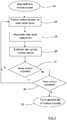
- the motion segmentation process according to the second processing step 14 above runs in the following segmentation steps as depicted in Figure 4 .
- a first motion subset 40 in a first segmentation step 23 for example corresponding to the first target object 6, the first motion subset 40 is in a second segmentation step 24 predicted for the next radar cycle, independently of other motion subsets 41, 42.
- a third segmentation step 25 new incoming radar detections in a next radar cycle are associated with the present motion subset.
- a fourth segmentation step 26 an updated group motion vector is estimated.
- a fifth segmentation step 27 it is checked if there are more motion subsets, and the second to fourth segmentation steps 24, 25, 26 are repeated for all available motion subsets. In order to propagate the present motion subset 40 to a next radar cycle, this motion subset 40 is first predicted, new radar detections are associated, and finally the group motion vector is updated.
- new motion subsets are searched for by means of unassociated detections in a sixth segmentation step 28. Possible new motion subsets are processed according to the second to fourth segmentation steps. When there are no new motion subsets, an updated list M u of motion subsets is created in a seventh segmentation step 29.
- each target object 6, 7, 8 corresponds to a motion subset 40, 41, 42 that is represented by a corresponding group motion vector V 1 , V 2 , V 3 and a labelling of the associated detections.
- No further abstractions such as position, box model, etc. are needed to describe the state of a motion subset. This is advantageous since no model fitting is needed; instead each motion subset 40, 41, 42 is described directly from the input data. This provides robustness against noise and erroneous prone fitting algorithms.
- the second segmentation step 24 prediction is performed based on the radar detections 9, 10, 11 which belong to a given motion subset 40, 41, 42. For each motion subset 40, 41, 42, each one of the corresponding detections 9, 10, 11 is moved in the x- and y-direction according to the present group motion vector. According to some aspects, data from multiple previous cycles, which are stored in the detection memory 12, are used. This means that radar detections 9, 10, 11 which are associated with a certain motion subset 40, 41, 42 are predicted from several previous radar cycles.
- association is performed by spatial considerations where new radar detections from the next cycle are associated, i.e. considered for an update, if they are close enough to any of the corresponding radar detections belonging to a certain motion subset. This does not rely on model information and depends only on the position of the predicted detections of said motion subset. In this way, a non-parametric extended shape model is realized. Furthermore, additional robustness of this non-parametric model is achieved by including detections from several previous radar cycles, stored in the detection memory, in the association process. The shape of a tracked object is then defined by associated detections from several previous radar cycles.
- the radar detections which are spatially close are considered inlier candidates.
- a full group motion vector is estimated using the angle and Doppler velocity information. It is assumed that detections belonging to the same object have a shared group motion vector.
- the projection of this group motion vector onto the radial direction of each individual detection, determined by the measured angle, corresponds to the measured Doppler velocity. This corresponds to: v 1 v 2 ⁇ v n cos ⁇ 1 sin ⁇ 1 cos ⁇ 2 sin ⁇ 2 ⁇ ⁇ cos ⁇ n sin ⁇ n ⁇ v x v y .
- Inverting equation (1) results in an estimate of the group motion vector v x v y .
- Some measured angles ⁇ i and measured Doppler velocities v i of the radar detections 9, 10, 11 are noisy and outliers, for example due to rotating wheels, can result in deviation from this ideal equation. Radar detections 22 that are due to noise are shown with dots in Figure 1 and Figure 2 . Therefore, in practice and to increase robustness, robust estimators such as RANSAC(Random sample consensus) can be used to reject outliers from this estimation process. Outliers are then removed and inliers remain. Then each detection is labelled with the additional information f i indicating whether it is an inlier or outlier with respect to the velocity profile. In later processing stages, this can for example be utilized for wheel detection and object classification.
- RANSAC Random sample consensus
- Physical objects are typically seen by the radar sensor arrangement 3 as multiple detections per radar cycle, especially in a near range. In some situations, there can be a smaller number of detections. This is the case for example at a far range, or for small objects such as pedestrians.
- the detection memory (12) is used to also store detections from previous radar cycles. In this way, even with a low number of detections per cycle, a full group velocity estimate according to equation (1) is possible.
- the first target object 6 and the second target object 7, as well as their corresponding motion subsets 40, 41 are spatially close to each other.
- One of the detections, the ambiguous radar detection 21, is associated to both motion subsets 40, 41 because of its spatial proximity.
- this ambiguous radar detection 21 also fulfills the velocity profile according to equation (1) and is therefore close to both the first cosine curve and the second cosine curve as discussed previously.
- This radar detection 21 is indicated as determined to constitute an ambiguous radar detection for two or more motion subsets 40, 41, which is vital information for the processing unit 4 in further processing stages.
- an extended object tracking algorithm can be adapted to ignore ambiguous detections when shape estimation is performed.
- Distinct motion subsets, and then also corresponding target objects 38, 39, can become indistinguishable from each other if the corresponding targets objects get too close to each other and also more or less move in the same direction.
- two distinct motion subsets 31, 32 can result from a single physical target object 33 that can be relatively large. Both these motion subsets 31, 32 have equal group motion vectors V A1 , V A2 , and in the azimuth angle vs. Doppler velocity domain, the two corresponding cosine curves overlap. In this case many, or even all, associated radar detections 34, 35, 36 are determined to be ambiguous.
- the processing unit 4 is arranged to perform a merge function for merging two motion subsets 31, 32 into one merged subset 37.
- the processing unit 4 is arranged to check for detections that have been determined to be ambiguous and to check if the associated motion subsets have equal, or at least very similar, group motion vectors V A1 , V A2 . If that is the case, the processing unit 4 is arranged to merge two motion subsets 31, 32 and the corresponding radar detections 34 into a resulting merged motion subset 37, and consequently the corresponding target objects 38, 39 are merged to one and the same corresponding target object 33 having one group motion vectors V A .
- the processing unit 4 is arranged to perform averaging or a similar approach that provides a merged group velocity vector.
- the processing unit 4 is arranged to model the spatial extent of the merged motion subset by labelling the associated detections. All the corresponding labelled detections only need to be assigned the identification of the merged motion subset.
- the non-parametric shape model is thus beneficial for target object merging of this kind.
- the processing unit 4 is arranged to determine that radar detections which are not associated with any existing motion subset are unassociated. For unassociated radar detections, a seeker algorithm can search for new motion subsets. According to some aspects, classical seeker algorithms which are arranged to search a consistent stream of single detections can be used. However, directly estimating a full group motion vector using detections from a single radar cycle by applying equation (1) is also conceivable. This allows for very fast object initialization, especially in the near range where objects typically reflect from multiple angles and thus result in multiple detections.
- the present disclosure also relates to a method for obtaining a synthetic antenna aperture using a radar sensor arrangement 3 that uses an antenna device 47 with a physical antenna aperture 49.
- the radar sensor arrangement 3 is used in a coordinate system 48 for receiving radar signals 9, 10, 11 outside a vehicle.
- the method comprises:
- the radar sensor arrangement 3 is assumed to be of a previously known design, for example comprising a radar transmitter, a radar receiver and a receiving antenna array.
- the radar sensor arrangement 3 may furthermore comprise a number of other parts, and is for example connected to a warning and/or information device comprised in the vehicle 1 in a previously known manner.
- the calculations and determining procedures are performed by the processing unit 4, where the processing unit 4 should be regarded as a processing unit arrangement that is in the form of one unit or several units that either co-operate or handle different tasks more or less independently. In the case of several units, these may be placed adjacent to each other, or in a distributed manner.
- the vehicle environment detection system comprises other detection devices such as a camera device 30. LIDAR devices and other similar arrangements are also conceivable. According to some aspects, the vehicle environment detection system comprises several detection devices of a certain type, such as for example several radar sensor arrangements that are adapted to cover different fields of view.
- the present disclosure enables a motion model of each target object relative to the radar sensor arrangement to be determined.
- the motion model in turn enables an inverse SAR technique to be applied to the already received and stored radar signals such that a synthetic aperture view is obtained.
- said processing unit 4 is arranged to:
- said processing unit 4 is arranged to:
- said processing unit 4 is arranged to determine that radar detections which are not associated with any existing motion subset are unassociated, where said processing unit 4 is arranged to seek for new motion subsets for said unassociated radar detections.
- said processing unit 4 is arranged to:
- the present disclosure also relates to a method for obtaining a synthetic antenna aperture using a radar sensor arrangement 3 that uses an antenna device 47 with a physical antenna aperture 49, where the radar sensor arrangement 3 is used in a coordinate system 48 for receiving radar signals 9, 10, 11 outside a vehicle 1, where the method comprises:
- the method comprises:
- the method comprises:
- the method comprises:
- the method comprises:
Landscapes
- Engineering & Computer Science (AREA)
- Remote Sensing (AREA)
- Radar, Positioning & Navigation (AREA)
- Physics & Mathematics (AREA)
- Computer Networks & Wireless Communication (AREA)
- General Physics & Mathematics (AREA)
- Electromagnetism (AREA)
- Radar Systems Or Details Thereof (AREA)
Claims (10)
- Fahrzeugumgebungserfassungssystem (2), das mindestens eine Radarsensoranordnung (3) und mindestens eine Verarbeitungseinheit (4) umfasst, wobei die Radarsensoranordnung (3) eine Antennenvorrichtung (47) umfasst, die eine physikalische Antennenapertur (49) mit einem gewissen Sichtfeld (5) aufweist, wobei die Radarsensoranordnung (3) dazu eingerichtet ist, mindestens zwei Radarerfassungen (9, 10, 11) in einem Koordinatensystem (48) während mindestens zwei Radarzyklen zu erfassen, wobei die Verarbeitungseinheit (4) dazu eingerichtet ist, für jeden Radarzyklus eine Erfassungsliste


 - eine relative Bewegung zwischen mindestens einem Zielobjekt (6, 7, 8) und der Antennenvorrichtung (47) mithilfe des Gruppenbewegungsvektors (V1, V2, V3) zu bestimmen;- das Koordinatensystem (48) zu kartieren, so dass das Zielobjekt (6, 7, 8) stationär ist und so dass die Antennenvorrichtung (47) eine bestimmte Bewegung aufweist; und- eine synthetische Antennenapertur mithilfe bezogener Radarsignale in bekannten Zeitintervallen und mithilfe der bestimmten Bewegung der Antennenvorrichtung (47) zu erzeugen, so dass der physikalischen Antennenapertur (49) eine bestimmte Bewegung im Zeitablauf verliehen wird.
 - Fahrzeugumgebungserfassungssystem (2) nach Anspruch 1, dadurch gekennzeichnet, dass die Verarbeitungseinheit (4) dazu eingerichtet ist, für jeden Radarzyklus:- eine Ausgabeliste (M) von Bewegungsteilsätzen (40, 41, 42) zu erzeugen, wobei die Ausgabeliste (M) einen Gruppenbewegungsvektor (Vk) für jeden Bewegungsteilsatz (40, 41, 42) umfasst und wobei jeder Gruppenbewegungsvektor (Vk) eine Gruppenbewegung eines jeweiligen Bewegungsteilsatzes (40, 41, 42) darstellt; und- eine Etikettierung (Li) für jede eingegebene Erfassung zu erzeugen, wobei die Etikettierung (Li) für jede Radarerfassung eine Objektkennung (li), die beschreibt, zu welchem Bewegungsteilsatz eine gegebene Radarerfassung gehört, und zusätzliche Markierungen (fi) für jede Radarerfassung umfasst.
- Fahrzeugumgebungserfassungssystem (2) nach Anspruch 2, dadurch gekennzeichnet, dass, um den Segmentierungsvorgang durchzuführen, die Verarbeitungseinheit (4) dazu eingerichtet ist, für jeden von allen verfügbaren Bewegungsteilsätzen:- einen aktuellen Bewegungsteilsatz (40) für den nächsten Radarzyklus unabhängig von anderen Bewegungsteilsätzen (41, 42) vorherzusagen;- neue Radarerfassungen mit dem aktuellen Bewegungsteilsatz (40) zu assoziieren und- einen aktualisierten Gruppenbewegungsvektor zu erzeugen;wobei die Verarbeitungseinheit (4) ferner dazu eingerichtet ist, eine aktualisierte Liste (Mu) von Bewegungsteilsätzen zu erzeugen.
- Fahrzeugumgebungserfassungssystem (2) nach Anspruch 3, dadurch gekennzeichnet, dass die Verarbeitungseinheit (4) dazu eingerichtet ist, zu bestimmen, dass Radarerfassungen, die nicht mit einem beliebigen existierenden Bewegungsteilsatz assoziiert sind, nicht assoziiert sind, wobei die Verarbeitungseinheit (4) dazu eingerichtet ist, nach neuen Bewegungsteilsätzen für die nicht assoziierten Radarerfassungen zu suchen.
- Fahrzeugumgebungserfassungssystem (2) nach einem der vorhergehenden Ansprüche, dadurch gekennzeichnet, dass die Verarbeitungseinheit (4) dazu eingerichtet ist:zu erfassen, ob mindestens zwei Bewegungsteilsätze (31, 32) gleiche Gruppenbewegungsvektoren (VA1, VA2) aufweisen; undzu erfassen, ob die Radarerfassungen (34, 35, 36) einer jeweiligen gemeinsamen Kosinuskurve in einem Azimutwinkel-versus-Dopplergeschwindigkeit-Bereich folgen, wobei die entsprechenden Kosinuskurven sich überschneiden,und wenn bestimmt wird, dass das der Fall ist, die Verarbeitungseinheit (4) dazu eingerichtet ist, die Bewegungsteilsätze (31, 32) zu einem fusionierten Bewegungsteilsatz (37) zu fusionieren.
- Verfahren zum Erhalten einer synthetischen Antennenapertur unter Verwendung einer Radarsensoranordnung (3), die eine Antennenvorrichtung (47) mit einer physikalischen Antennenapertur (49) verwendet, wobei die Radarsensoranordnung (3) in einem Koordinatensystem (48) zum Empfangen von Radarsignalen (9, 10, 11) außerhalb eines Fahrzeugs (1) verwendet wird, wobei das Verfahren umfasst:(43) Erfassen von mindestens zwei Radarerfassungen (9, 10, 11) in dem Koordinatensystem (48) während mindestens zwei Radarzyklen und(44) für jeden Radarzyklus Erzeugen einer Erfassungsliste
 (45)Aggregieren und Speichern von Erfassungslisten
 (46) Gruppieren der Radarerfassungen (9, 10, 11) in den Erfassungslisten
 (50) Bestimmen eines entsprechenden Gruppenbewegungsvektors (V1, V2, V3);(51) Bestimmen einer relativen Bewegung zwischen mindestens einem Zielobjekt (6, 7, 8) und der Antennenvorrichtung (47) mithilfe des Gruppenbewegungsvektors (V1, V2, V3);(52) Kartieren des Koordinatensystems (48), so dass das Zielobjekt (6, 7, 8) stationär ist und so dass die Antennenvorrichtung (47) eine bestimmte Bewegung aufweist; und(53) Erzeugen einer synthetischen Antennenapertur mithilfe bezogener Radarsignale in bekannten Zeitintervallen und durch Verwenden der bestimmten Bewegung der Antennenvorrichtung (47), so dass der physikalischen Antennenapertur (49) eine bestimmte Bewegung im Zeitablauf verliehen wird.
 - Verfahren nach Anspruch 6, dadurch gekennzeichnet, dass das Verfahren für jeden Radarzyklus umfasst:- Erzeugen einer Ausgabeliste (M) von Bewegungsteilsätzen (40, 41, 42), wobei die Ausgabeliste (M) einen Gruppenbewegungsvektor (Vk) für jeden Bewegungsteilsatz (40, 41, 42) umfasst und wobei jeder Gruppenbewegungsvektor (Vk) eine Gruppenbewegung eines jeweiligen Bewegungsteilsatzes (40, 41, 42) darstellt; und- Erzeugen einer Etikettierung (Li) für jede eingegebene Erfassung, wobei die Etikettierung (Li) für jede Radarerfassung eine Objektkennung (li), die beschreibt, zu welchem Bewegungsteilsatz eine gegebene Radarerfassung gehört, und zusätzliche Markierungen (fi) für jede Radarerfassung umfasst.
- Verfahren nach Anspruch 7, dadurch gekennzeichnet, dass, um den Segmentierungsvorgang durchzuführen, das Verfahren für jeden von allen verfügbaren Bewegungsteilsätzen umfasst:(24) Vorhersagen eines aktuellen Bewegungsteilsatzes (40) für den nächsten Radarzyklus unabhängig von anderen Bewegungsteilsätzen (41, 42);(25) Assoziieren neuer Radarerfassungen mit dem aktuellen Bewegungsteilsatz (40); und(26) Erzeugen eines aktualisierten Gruppenbewegungsvektors;wobei das Verfahren ferner ein Erzeugen einer aktualisierten Liste (Mu) von Bewegungsteilsätzen umfasst.
- Verfahren nach Anspruch 8, dadurch gekennzeichnet, dass das Verfahren umfasst:- Bestimmen, dass Radarerfassungen, die nicht mit einem beliebigen existierenden Bewegungsteilsatz assoziiert sind, nicht assoziiert sind; und- Suchen nach neuen Bewegungsteilsätzen für die nicht assoziierten Radarerfassungen.
- Verfahren nach einem der Ansprüche 6-9, dadurch gekennzeichnet, dass das Verfahren umfasst:- Erfassen, ob mindestens zwei Bewegungsteilsätze (31, 32) gleiche Gruppenbewegungsvektoren (VA1, VA2) aufweisen; und- Erfassen, ob die Radarerfassungen (34, 35, 36) einer jeweiligen gemeinsamen Kosinuskurve in einem Azimutwinkel-versus-Dopplergeschwindigkeit-Bereich folgen, wobei die entsprechenden Kosinuskurven sich überschneiden,und wenn bestimmt wird, dass das der Fall ist, das Verfahren ein Fusionieren der Bewegungsteilsätze (31, 32) zu einem fusionierten Bewegungsteilsatz (37) umfasst.
Priority Applications (4)
| Application Number | Priority Date | Filing Date | Title |
|---|---|---|---|
| EP17157547.5A EP3367121B1 (de) | 2017-02-23 | 2017-02-23 | Radar mit inverser synthetischer apertur für ein radarsystem eines kraftfahrzeugs |
| CN201880013312.2A CN110325876B (zh) | 2017-02-23 | 2018-02-22 | 用于车辆雷达系统的逆合成孔径雷达 |
| PCT/EP2018/054389 WO2018153988A1 (en) | 2017-02-23 | 2018-02-22 | Inverted synthetic aperture radar for a vehicle radar system |
| JP2019542718A JP6733060B2 (ja) | 2017-02-23 | 2018-02-22 | 車両レーダシステム用の逆合成開口レーダ |
Applications Claiming Priority (1)
| Application Number | Priority Date | Filing Date | Title |
|---|---|---|---|
| EP17157547.5A EP3367121B1 (de) | 2017-02-23 | 2017-02-23 | Radar mit inverser synthetischer apertur für ein radarsystem eines kraftfahrzeugs |
Publications (2)
| Publication Number | Publication Date |
|---|---|
| EP3367121A1 EP3367121A1 (de) | 2018-08-29 |
| EP3367121B1 true EP3367121B1 (de) | 2020-04-08 |
Family
ID=58158899
Family Applications (1)
| Application Number | Title | Priority Date | Filing Date |
|---|---|---|---|
| EP17157547.5A Not-in-force EP3367121B1 (de) | 2017-02-23 | 2017-02-23 | Radar mit inverser synthetischer apertur für ein radarsystem eines kraftfahrzeugs |
Country Status (4)
| Country | Link |
|---|---|
| EP (1) | EP3367121B1 (de) |
| JP (1) | JP6733060B2 (de) |
| CN (1) | CN110325876B (de) |
| WO (1) | WO2018153988A1 (de) |
Cited By (6)
| Publication number | Priority date | Publication date | Assignee | Title |
|---|---|---|---|---|
| WO2022094430A1 (en) * | 2020-11-02 | 2022-05-05 | Waymo Llc | Point cloud segmentation using a coherent lidar for autonomous vehicle applications |
| US12050267B2 (en) | 2020-11-09 | 2024-07-30 | Waymo Llc | Doppler-assisted object mapping for autonomous vehicle applications |
| US12153437B2 (en) | 2020-12-08 | 2024-11-26 | Waymo Llc | Detection of particulate matter in autonomous vehicle applications |
| US12181878B2 (en) | 2020-10-22 | 2024-12-31 | Waymo Llc | Velocity estimation and object tracking for autonomous vehicle applications |
| US12216474B1 (en) | 2021-05-04 | 2025-02-04 | Waymo Llc | Vibrometry-based behavior prediction for autonomous vehicle applications |
| US12233905B2 (en) | 2020-11-02 | 2025-02-25 | Waymo Llc | Classification of objects based on motion patterns for autonomous vehicle applications |
Families Citing this family (2)
| Publication number | Priority date | Publication date | Assignee | Title |
|---|---|---|---|---|
| DE102020123293A1 (de) * | 2020-09-07 | 2022-03-10 | Friedrich-Alexander-Universität Erlangen-Nürnberg | Verfahren, Radarsystem und Fahrzeug zur Signalverarbeitung von Radarsignalen |
| JP2022181125A (ja) * | 2021-05-25 | 2022-12-07 | ソニーグループ株式会社 | 情報処理装置、キャリブレーションシステム及び情報処理方法 |
Family Cites Families (18)
| Publication number | Priority date | Publication date | Assignee | Title |
|---|---|---|---|---|
| IT1231358B (it) * | 1989-04-21 | 1991-12-02 | Selenia Ind Elettroniche | Dispositivo per migliorare la risoluzione radar |
| DE19706576A1 (de) * | 1997-02-20 | 1998-08-27 | Alsthom Cge Alcatel | Vorrichtung und Verfahren zur umgebungsadaptiven Klassifikation von Objekten |
| JP2930236B1 (ja) * | 1998-01-26 | 1999-08-03 | 本田技研工業株式会社 | レーダ装置 |
| JP2003279647A (ja) * | 2002-03-26 | 2003-10-02 | Mitsubishi Electric Corp | 目標識別装置、目標識別方法及びプログラム |
| US7498940B2 (en) * | 2004-06-22 | 2009-03-03 | Vubiq, Inc. | RFID system utilizing parametric reradiated technology |
| GB0701869D0 (en) * | 2007-01-31 | 2007-03-14 | Cambridge Consultants | Adaptive radar |
| JP2009109293A (ja) * | 2007-10-29 | 2009-05-21 | Mitsubishi Electric Corp | 目標追尾装置及び目標観測システム及び目標追尾方法及びプログラム |
| DE102008025773A1 (de) | 2008-05-29 | 2009-01-08 | Daimler Ag | Verfahren zur Schätzung eines Orts- und Bewegungszustands eines beobachteten Objekts |
| JP5424667B2 (ja) * | 2008-06-02 | 2014-02-26 | 三菱電機株式会社 | 画像レーダ装置 |
| KR101775572B1 (ko) * | 2009-04-06 | 2017-09-06 | 콘티 테믹 마이크로일렉트로닉 게엠베하 | 송신 신호와 수신 신호를 디커플링하고 간섭 방사를 억제하기 위한 어레이와 방법을 채용한 레이더 시스템 |
| DE102010015723B4 (de) * | 2010-04-21 | 2023-10-12 | Volkswagen Ag | Verfahren und Vorrichtung zum Erfassen einer Bewegung eines Straßenfahrzeugs |
| CN103091682B (zh) * | 2011-11-04 | 2014-06-25 | 中国科学院电子学研究所 | 基于时频分析InISAR多动目标成像和运动轨迹重建法 |
| US9500742B2 (en) * | 2012-06-28 | 2016-11-22 | Autoliv Development Ab | Misalignment processing for a vehicle radar sensor |
| EP3132283A4 (de) * | 2014-04-14 | 2017-11-15 | Vricon Systems AB | Verfahren und system zum rendering eines bildes eines radars mit synthetischer apertur |
| CN104297759B (zh) * | 2014-10-23 | 2016-09-21 | 中国科学院上海光学精密机械研究所 | 双曲波前差自扫描直视合成孔径激光成像雷达 |
| CN104730507B (zh) * | 2015-04-01 | 2017-06-16 | 苏州闻捷传感技术有限公司 | 基于预调制aic雷达距离成像的车载路障告警方法 |
| GB2541658B (en) * | 2015-08-24 | 2020-01-01 | Thales Holdings Uk Plc | Video-assisted inverse synthetic aperture radar (VAISAR) |
| JP6650344B2 (ja) * | 2015-10-02 | 2020-02-19 | パナソニック株式会社 | 物体検出装置及び物体検出方法 |
-
2017
- 2017-02-23 EP EP17157547.5A patent/EP3367121B1/de not_active Not-in-force
-
2018
- 2018-02-22 JP JP2019542718A patent/JP6733060B2/ja not_active Expired - Fee Related
- 2018-02-22 WO PCT/EP2018/054389 patent/WO2018153988A1/en not_active Ceased
- 2018-02-22 CN CN201880013312.2A patent/CN110325876B/zh not_active Expired - Fee Related
Non-Patent Citations (1)
| Title |
|---|
| None * |
Cited By (7)
| Publication number | Priority date | Publication date | Assignee | Title |
|---|---|---|---|---|
| US12181878B2 (en) | 2020-10-22 | 2024-12-31 | Waymo Llc | Velocity estimation and object tracking for autonomous vehicle applications |
| WO2022094430A1 (en) * | 2020-11-02 | 2022-05-05 | Waymo Llc | Point cloud segmentation using a coherent lidar for autonomous vehicle applications |
| US12233905B2 (en) | 2020-11-02 | 2025-02-25 | Waymo Llc | Classification of objects based on motion patterns for autonomous vehicle applications |
| US12270914B2 (en) | 2020-11-02 | 2025-04-08 | Waymo Llc | Point cloud segmentation using a coherent lidar for autonomous vehicle applications |
| US12050267B2 (en) | 2020-11-09 | 2024-07-30 | Waymo Llc | Doppler-assisted object mapping for autonomous vehicle applications |
| US12153437B2 (en) | 2020-12-08 | 2024-11-26 | Waymo Llc | Detection of particulate matter in autonomous vehicle applications |
| US12216474B1 (en) | 2021-05-04 | 2025-02-04 | Waymo Llc | Vibrometry-based behavior prediction for autonomous vehicle applications |
Also Published As
| Publication number | Publication date |
|---|---|
| WO2018153988A1 (en) | 2018-08-30 |
| JP6733060B2 (ja) | 2020-07-29 |
| CN110325876B (zh) | 2023-05-19 |
| JP2020507767A (ja) | 2020-03-12 |
| CN110325876A (zh) | 2019-10-11 |
| EP3367121A1 (de) | 2018-08-29 |
Similar Documents
| Publication | Publication Date | Title |
|---|---|---|
| EP3367121B1 (de) | Radar mit inverser synthetischer apertur für ein radarsystem eines kraftfahrzeugs | |
| US11215707B2 (en) | Enhanced object detection and motion estimation for a vehicle environment detection system | |
| EP3252501B1 (de) | Verbesserte objekterkennung und bewegungsstatusschätzung für ein fahrzeugumgebungserkennungssystem | |
| EP3663790B1 (de) | Verfahren und vorrichtung zur verarbeitung von radardaten | |
| EP3285230B1 (de) | Verbesserte objekterkennung und bewegungsschätzung für ein fahrzeugumgebungserkennungssystem | |
| EP3415945B1 (de) | Verfahren zur bestimmung der gierrate eines zielfahrzeugs | |
| US10605896B2 (en) | Radar-installation-angle calculating device, radar apparatus, and radar-installation-angle calculating method | |
| CN104793202B (zh) | 多雷达成像传感器的对象融合系统 | |
| Kellner et al. | Instantaneous lateral velocity estimation of a vehicle using Doppler radar | |
| CN111386476B (zh) | 确定车辆雷达系统中的对象运动和加速度矢量 | |
| CN114814761B (zh) | 用于车辆自我运动估计的雷达数据处理 | |
| CN111819466B (zh) | 用于定位场景中的目标的装置、系统及方法 | |
| EP3575827B1 (de) | Verfahren zur robusten schätzung der geschwindigkeit eines ziels mithilfe eines host-fahrzeugs | |
| CN114814762B (zh) | 用于车辆自我运动估计的雷达数据处理 | |
| EP4045942A1 (de) | Verfahren zur abschätzung der eigengeschwindigkeit eines fahrzeugs | |
| Stolz et al. | Direction of movement estimation of cyclists with a high-resolution automotive radar | |
| Michaelis et al. | Generating odometry measurements from automotive radar doppler measurements | |
| CN115201828A (zh) | 稀疏点云的优化方法、系统、电子设备、存储介质 | |
| Li et al. | Environment mapping and vehicle localization with a high-resolution radar prototype | |
| Schuster et al. | Target tracking in marine environment using automotive radar and laser range sensor | |
| US12578454B2 (en) | Ego velocity assisted direction of arrival estimator for radar systems | |
| Kim et al. | Instantaneous Longitudinal Ego-Velocity Estimation Using 4D Radar-Camera Fusion in Dynamic Road Environments |
Legal Events
| Date | Code | Title | Description |
|---|---|---|---|
| PUAI | Public reference made under article 153(3) epc to a published international application that has entered the european phase |
Free format text: ORIGINAL CODE: 0009012 |
|
| STAA | Information on the status of an ep patent application or granted ep patent |
Free format text: STATUS: THE APPLICATION HAS BEEN PUBLISHED |
|
| AK | Designated contracting states |
Kind code of ref document: A1 Designated state(s): AL AT BE BG CH CY CZ DE DK EE ES FI FR GB GR HR HU IE IS IT LI LT LU LV MC MK MT NL NO PL PT RO RS SE SI SK SM TR |
|
| AX | Request for extension of the european patent |
Extension state: BA ME |
|
| STAA | Information on the status of an ep patent application or granted ep patent |
Free format text: STATUS: REQUEST FOR EXAMINATION WAS MADE |
|
| 17P | Request for examination filed |
Effective date: 20190221 |
|
| RBV | Designated contracting states (corrected) |
Designated state(s): AL AT BE BG CH CY CZ DE DK EE ES FI FR GB GR HR HU IE IS IT LI LT LU LV MC MK MT NL NO PL PT RO RS SE SI SK SM TR |
|
| REG | Reference to a national code |
Ref country code: DE Ref legal event code: R079 Ref document number: 602017014193 Country of ref document: DE Free format text: PREVIOUS MAIN CLASS: G01S0013720000 Ipc: G01S0013420000 |
|
| RIC1 | Information provided on ipc code assigned before grant |
Ipc: G01S 13/42 20060101AFI20190807BHEP Ipc: G01S 13/86 20060101ALI20190807BHEP Ipc: G01S 13/93 20060101ALI20190807BHEP Ipc: G01S 13/72 20060101ALI20190807BHEP Ipc: G01S 13/58 20060101ALI20190807BHEP Ipc: G01S 13/90 20060101ALI20190807BHEP |
|
| GRAP | Despatch of communication of intention to grant a patent |
Free format text: ORIGINAL CODE: EPIDOSNIGR1 |
|
| STAA | Information on the status of an ep patent application or granted ep patent |
Free format text: STATUS: GRANT OF PATENT IS INTENDED |
|
| INTG | Intention to grant announced |
Effective date: 20191002 |
|
| GRAS | Grant fee paid |
Free format text: ORIGINAL CODE: EPIDOSNIGR3 |
|
| GRAA | (expected) grant |
Free format text: ORIGINAL CODE: 0009210 |
|
| STAA | Information on the status of an ep patent application or granted ep patent |
Free format text: STATUS: THE PATENT HAS BEEN GRANTED |
|
| AK | Designated contracting states |
Kind code of ref document: B1 Designated state(s): AL AT BE BG CH CY CZ DE DK EE ES FI FR GB GR HR HU IE IS IT LI LT LU LV MC MK MT NL NO PL PT RO RS SE SI SK SM TR |
|
| REG | Reference to a national code |
Ref country code: AT Ref legal event code: REF Ref document number: 1255136 Country of ref document: AT Kind code of ref document: T Effective date: 20200415 Ref country code: CH Ref legal event code: EP |
|
| REG | Reference to a national code |
Ref country code: DE Ref legal event code: R096 Ref document number: 602017014193 Country of ref document: DE |
|
| REG | Reference to a national code |
Ref country code: IE Ref legal event code: FG4D |
|
| REG | Reference to a national code |
Ref country code: SE Ref legal event code: TRGR |
|
| REG | Reference to a national code |
Ref country code: NL Ref legal event code: MP Effective date: 20200408 |
|
| REG | Reference to a national code |
Ref country code: LT Ref legal event code: MG4D |
|
| PG25 | Lapsed in a contracting state [announced via postgrant information from national office to epo] |
Ref country code: FI Free format text: LAPSE BECAUSE OF FAILURE TO SUBMIT A TRANSLATION OF THE DESCRIPTION OR TO PAY THE FEE WITHIN THE PRESCRIBED TIME-LIMIT Effective date: 20200408 Ref country code: NL Free format text: LAPSE BECAUSE OF FAILURE TO SUBMIT A TRANSLATION OF THE DESCRIPTION OR TO PAY THE FEE WITHIN THE PRESCRIBED TIME-LIMIT Effective date: 20200408 Ref country code: LT Free format text: LAPSE BECAUSE OF FAILURE TO SUBMIT A TRANSLATION OF THE DESCRIPTION OR TO PAY THE FEE WITHIN THE PRESCRIBED TIME-LIMIT Effective date: 20200408 Ref country code: PT Free format text: LAPSE BECAUSE OF FAILURE TO SUBMIT A TRANSLATION OF THE DESCRIPTION OR TO PAY THE FEE WITHIN THE PRESCRIBED TIME-LIMIT Effective date: 20200817 Ref country code: GR Free format text: LAPSE BECAUSE OF FAILURE TO SUBMIT A TRANSLATION OF THE DESCRIPTION OR TO PAY THE FEE WITHIN THE PRESCRIBED TIME-LIMIT Effective date: 20200709 Ref country code: NO Free format text: LAPSE BECAUSE OF FAILURE TO SUBMIT A TRANSLATION OF THE DESCRIPTION OR TO PAY THE FEE WITHIN THE PRESCRIBED TIME-LIMIT Effective date: 20200708 Ref country code: IS Free format text: LAPSE BECAUSE OF FAILURE TO SUBMIT A TRANSLATION OF THE DESCRIPTION OR TO PAY THE FEE WITHIN THE PRESCRIBED TIME-LIMIT Effective date: 20200808 |
|
| REG | Reference to a national code |
Ref country code: AT Ref legal event code: MK05 Ref document number: 1255136 Country of ref document: AT Kind code of ref document: T Effective date: 20200408 |
|
| PG25 | Lapsed in a contracting state [announced via postgrant information from national office to epo] |
Ref country code: BG Free format text: LAPSE BECAUSE OF FAILURE TO SUBMIT A TRANSLATION OF THE DESCRIPTION OR TO PAY THE FEE WITHIN THE PRESCRIBED TIME-LIMIT Effective date: 20200708 Ref country code: RS Free format text: LAPSE BECAUSE OF FAILURE TO SUBMIT A TRANSLATION OF THE DESCRIPTION OR TO PAY THE FEE WITHIN THE PRESCRIBED TIME-LIMIT Effective date: 20200408 Ref country code: LV Free format text: LAPSE BECAUSE OF FAILURE TO SUBMIT A TRANSLATION OF THE DESCRIPTION OR TO PAY THE FEE WITHIN THE PRESCRIBED TIME-LIMIT Effective date: 20200408 Ref country code: HR Free format text: LAPSE BECAUSE OF FAILURE TO SUBMIT A TRANSLATION OF THE DESCRIPTION OR TO PAY THE FEE WITHIN THE PRESCRIBED TIME-LIMIT Effective date: 20200408 |
|
| PG25 | Lapsed in a contracting state [announced via postgrant information from national office to epo] |
Ref country code: AL Free format text: LAPSE BECAUSE OF FAILURE TO SUBMIT A TRANSLATION OF THE DESCRIPTION OR TO PAY THE FEE WITHIN THE PRESCRIBED TIME-LIMIT Effective date: 20200408 |
|
| REG | Reference to a national code |
Ref country code: DE Ref legal event code: R097 Ref document number: 602017014193 Country of ref document: DE |
|
| PG25 | Lapsed in a contracting state [announced via postgrant information from national office to epo] |
Ref country code: AT Free format text: LAPSE BECAUSE OF FAILURE TO SUBMIT A TRANSLATION OF THE DESCRIPTION OR TO PAY THE FEE WITHIN THE PRESCRIBED TIME-LIMIT Effective date: 20200408 Ref country code: EE Free format text: LAPSE BECAUSE OF FAILURE TO SUBMIT A TRANSLATION OF THE DESCRIPTION OR TO PAY THE FEE WITHIN THE PRESCRIBED TIME-LIMIT Effective date: 20200408 Ref country code: IT Free format text: LAPSE BECAUSE OF FAILURE TO SUBMIT A TRANSLATION OF THE DESCRIPTION OR TO PAY THE FEE WITHIN THE PRESCRIBED TIME-LIMIT Effective date: 20200408 Ref country code: SM Free format text: LAPSE BECAUSE OF FAILURE TO SUBMIT A TRANSLATION OF THE DESCRIPTION OR TO PAY THE FEE WITHIN THE PRESCRIBED TIME-LIMIT Effective date: 20200408 Ref country code: CZ Free format text: LAPSE BECAUSE OF FAILURE TO SUBMIT A TRANSLATION OF THE DESCRIPTION OR TO PAY THE FEE WITHIN THE PRESCRIBED TIME-LIMIT Effective date: 20200408 Ref country code: RO Free format text: LAPSE BECAUSE OF FAILURE TO SUBMIT A TRANSLATION OF THE DESCRIPTION OR TO PAY THE FEE WITHIN THE PRESCRIBED TIME-LIMIT Effective date: 20200408 Ref country code: ES Free format text: LAPSE BECAUSE OF FAILURE TO SUBMIT A TRANSLATION OF THE DESCRIPTION OR TO PAY THE FEE WITHIN THE PRESCRIBED TIME-LIMIT Effective date: 20200408 Ref country code: DK Free format text: LAPSE BECAUSE OF FAILURE TO SUBMIT A TRANSLATION OF THE DESCRIPTION OR TO PAY THE FEE WITHIN THE PRESCRIBED TIME-LIMIT Effective date: 20200408 |
|
| PLBE | No opposition filed within time limit |
Free format text: ORIGINAL CODE: 0009261 |
|
| STAA | Information on the status of an ep patent application or granted ep patent |
Free format text: STATUS: NO OPPOSITION FILED WITHIN TIME LIMIT |
|
| PG25 | Lapsed in a contracting state [announced via postgrant information from national office to epo] |
Ref country code: SK Free format text: LAPSE BECAUSE OF FAILURE TO SUBMIT A TRANSLATION OF THE DESCRIPTION OR TO PAY THE FEE WITHIN THE PRESCRIBED TIME-LIMIT Effective date: 20200408 Ref country code: PL Free format text: LAPSE BECAUSE OF FAILURE TO SUBMIT A TRANSLATION OF THE DESCRIPTION OR TO PAY THE FEE WITHIN THE PRESCRIBED TIME-LIMIT Effective date: 20200408 |
|
| 26N | No opposition filed |
Effective date: 20210112 |
|
| PG25 | Lapsed in a contracting state [announced via postgrant information from national office to epo] |
Ref country code: SI Free format text: LAPSE BECAUSE OF FAILURE TO SUBMIT A TRANSLATION OF THE DESCRIPTION OR TO PAY THE FEE WITHIN THE PRESCRIBED TIME-LIMIT Effective date: 20200408 |
|
| PG25 | Lapsed in a contracting state [announced via postgrant information from national office to epo] |
Ref country code: MC Free format text: LAPSE BECAUSE OF FAILURE TO SUBMIT A TRANSLATION OF THE DESCRIPTION OR TO PAY THE FEE WITHIN THE PRESCRIBED TIME-LIMIT Effective date: 20200408 |
|
| REG | Reference to a national code |
Ref country code: BE Ref legal event code: MM Effective date: 20210228 |
|
| PG25 | Lapsed in a contracting state [announced via postgrant information from national office to epo] |
Ref country code: LI Free format text: LAPSE BECAUSE OF NON-PAYMENT OF DUE FEES Effective date: 20210228 Ref country code: LU Free format text: LAPSE BECAUSE OF NON-PAYMENT OF DUE FEES Effective date: 20210223 Ref country code: CH Free format text: LAPSE BECAUSE OF NON-PAYMENT OF DUE FEES Effective date: 20210228 |
|
| PG25 | Lapsed in a contracting state [announced via postgrant information from national office to epo] |
Ref country code: IE Free format text: LAPSE BECAUSE OF NON-PAYMENT OF DUE FEES Effective date: 20210223 |
|
| PG25 | Lapsed in a contracting state [announced via postgrant information from national office to epo] |
Ref country code: BE Free format text: LAPSE BECAUSE OF NON-PAYMENT OF DUE FEES Effective date: 20210228 |
|
| REG | Reference to a national code |
Ref country code: DE Ref legal event code: R081 Ref document number: 602017014193 Country of ref document: DE Owner name: ARRIVER SOFTWARE AB, SE Free format text: FORMER OWNER: VEONEER SWEDEN AB, VARGARDA, SE Ref country code: DE Ref legal event code: R081 Ref document number: 602017014193 Country of ref document: DE Owner name: QUALCOMM AUTO LTD., GB Free format text: FORMER OWNER: VEONEER SWEDEN AB, VARGARDA, SE |
|
| PG25 | Lapsed in a contracting state [announced via postgrant information from national office to epo] |
Ref country code: CY Free format text: LAPSE BECAUSE OF FAILURE TO SUBMIT A TRANSLATION OF THE DESCRIPTION OR TO PAY THE FEE WITHIN THE PRESCRIBED TIME-LIMIT Effective date: 20200408 |
|
| PG25 | Lapsed in a contracting state [announced via postgrant information from national office to epo] |
Ref country code: HU Free format text: LAPSE BECAUSE OF FAILURE TO SUBMIT A TRANSLATION OF THE DESCRIPTION OR TO PAY THE FEE WITHIN THE PRESCRIBED TIME-LIMIT; INVALID AB INITIO Effective date: 20170223 |
|
| PG25 | Lapsed in a contracting state [announced via postgrant information from national office to epo] |
Ref country code: MK Free format text: LAPSE BECAUSE OF FAILURE TO SUBMIT A TRANSLATION OF THE DESCRIPTION OR TO PAY THE FEE WITHIN THE PRESCRIBED TIME-LIMIT Effective date: 20200408 |
|
| PGFP | Annual fee paid to national office [announced via postgrant information from national office to epo] |
Ref country code: DE Payment date: 20240109 Year of fee payment: 8 Ref country code: GB Payment date: 20240111 Year of fee payment: 8 |
|
| PGFP | Annual fee paid to national office [announced via postgrant information from national office to epo] |
Ref country code: SE Payment date: 20240208 Year of fee payment: 8 Ref country code: FR Payment date: 20240108 Year of fee payment: 8 |
|
| PG25 | Lapsed in a contracting state [announced via postgrant information from national office to epo] |
Ref country code: MT Free format text: LAPSE BECAUSE OF FAILURE TO SUBMIT A TRANSLATION OF THE DESCRIPTION OR TO PAY THE FEE WITHIN THE PRESCRIBED TIME-LIMIT Effective date: 20200408 |
|
| REG | Reference to a national code |
Ref country code: GB Ref legal event code: 732E Free format text: REGISTERED BETWEEN 20241031 AND 20241106 |
|
| REG | Reference to a national code |
Ref country code: GB Ref legal event code: 732E Free format text: REGISTERED BETWEEN 20250206 AND 20250212 |
|
| REG | Reference to a national code |
Ref country code: DE Ref legal event code: R081 Ref document number: 602017014193 Country of ref document: DE Owner name: QUALCOMM AUTO LTD., GB Free format text: FORMER OWNER: ARRIVER SOFTWARE AB, LINKOEPING, SE |
|
| REG | Reference to a national code |
Ref country code: DE Ref legal event code: R119 Ref document number: 602017014193 Country of ref document: DE |
|
| REG | Reference to a national code |
Ref country code: SE Ref legal event code: EUG |
|
| GBPC | Gb: european patent ceased through non-payment of renewal fee |
Effective date: 20250223 |
|
| PG25 | Lapsed in a contracting state [announced via postgrant information from national office to epo] |
Ref country code: TR Free format text: LAPSE BECAUSE OF FAILURE TO SUBMIT A TRANSLATION OF THE DESCRIPTION OR TO PAY THE FEE WITHIN THE PRESCRIBED TIME-LIMIT Effective date: 20200408 |
|
| PG25 | Lapsed in a contracting state [announced via postgrant information from national office to epo] |
Ref country code: DE Free format text: LAPSE BECAUSE OF NON-PAYMENT OF DUE FEES Effective date: 20250902 |
|
| PG25 | Lapsed in a contracting state [announced via postgrant information from national office to epo] |
Ref country code: GB Free format text: LAPSE BECAUSE OF NON-PAYMENT OF DUE FEES Effective date: 20250223 |
|
| PG25 | Lapsed in a contracting state [announced via postgrant information from national office to epo] |
Ref country code: FR Free format text: LAPSE BECAUSE OF NON-PAYMENT OF DUE FEES Effective date: 20250228 |