EP3367593B1 - Signalübertragungsverfahren, signalempfangsverfahren und entsprechende vorrichtung und system - Google Patents
Signalübertragungsverfahren, signalempfangsverfahren und entsprechende vorrichtung und system Download PDFInfo
- Publication number
- EP3367593B1 EP3367593B1 EP15908543.0A EP15908543A EP3367593B1 EP 3367593 B1 EP3367593 B1 EP 3367593B1 EP 15908543 A EP15908543 A EP 15908543A EP 3367593 B1 EP3367593 B1 EP 3367593B1
- Authority
- EP
- European Patent Office
- Prior art keywords
- spread spectrum
- signal
- tributary
- spectrum modulation
- subcarrier
- Prior art date
- Legal status (The legal status is an assumption and is not a legal conclusion. Google has not performed a legal analysis and makes no representation as to the accuracy of the status listed.)
- Active
Links
Images





Classifications
-
- H—ELECTRICITY
- H04—ELECTRIC COMMUNICATION TECHNIQUE
- H04B—TRANSMISSION
- H04B10/00—Transmission systems employing electromagnetic waves other than radio-waves, e.g. infrared, visible or ultraviolet light, or employing corpuscular radiation, e.g. quantum communication
- H04B10/50—Transmitters
- H04B10/516—Details of coding or modulation
- H04B10/5161—Combination of different modulation schemes
-
- H—ELECTRICITY
- H04—ELECTRIC COMMUNICATION TECHNIQUE
- H04B—TRANSMISSION
- H04B10/00—Transmission systems employing electromagnetic waves other than radio-waves, e.g. infrared, visible or ultraviolet light, or employing corpuscular radiation, e.g. quantum communication
- H04B10/50—Transmitters
- H04B10/501—Structural aspects
- H04B10/503—Laser transmitters
- H04B10/505—Laser transmitters using external modulation
- H04B10/5053—Laser transmitters using external modulation using a parallel, i.e. shunt, combination of modulators
-
- H—ELECTRICITY
- H04—ELECTRIC COMMUNICATION TECHNIQUE
- H04B—TRANSMISSION
- H04B1/00—Details of transmission systems, not covered by a single one of groups H04B3/00 - H04B13/00; Details of transmission systems not characterised by the medium used for transmission
- H04B1/69—Spread spectrum techniques
- H04B1/707—Spread spectrum techniques using direct sequence modulation
- H04B1/7073—Synchronisation aspects
- H04B1/7087—Carrier synchronisation aspects
-
- H—ELECTRICITY
- H04—ELECTRIC COMMUNICATION TECHNIQUE
- H04B—TRANSMISSION
- H04B10/00—Transmission systems employing electromagnetic waves other than radio-waves, e.g. infrared, visible or ultraviolet light, or employing corpuscular radiation, e.g. quantum communication
- H04B10/25—Arrangements specific to fibre transmission
- H04B10/2507—Arrangements specific to fibre transmission for the reduction or elimination of distortion or dispersion
-
- H—ELECTRICITY
- H04—ELECTRIC COMMUNICATION TECHNIQUE
- H04B—TRANSMISSION
- H04B10/00—Transmission systems employing electromagnetic waves other than radio-waves, e.g. infrared, visible or ultraviolet light, or employing corpuscular radiation, e.g. quantum communication
- H04B10/50—Transmitters
-
- H—ELECTRICITY
- H04—ELECTRIC COMMUNICATION TECHNIQUE
- H04B—TRANSMISSION
- H04B10/00—Transmission systems employing electromagnetic waves other than radio-waves, e.g. infrared, visible or ultraviolet light, or employing corpuscular radiation, e.g. quantum communication
- H04B10/50—Transmitters
- H04B10/516—Details of coding or modulation
- H04B10/54—Intensity modulation
-
- H—ELECTRICITY
- H04—ELECTRIC COMMUNICATION TECHNIQUE
- H04B—TRANSMISSION
- H04B10/00—Transmission systems employing electromagnetic waves other than radio-waves, e.g. infrared, visible or ultraviolet light, or employing corpuscular radiation, e.g. quantum communication
- H04B10/60—Receivers
- H04B10/66—Non-coherent receivers, e.g. using direct detection
- H04B10/69—Electrical arrangements in the receiver
- H04B10/697—Arrangements for reducing noise and distortion
-
- H—ELECTRICITY
- H04—ELECTRIC COMMUNICATION TECHNIQUE
- H04B—TRANSMISSION
- H04B7/00—Radio transmission systems, i.e. using radiation field
- H04B7/14—Relay systems
- H04B7/15—Active relay systems
- H04B7/204—Multiple access
- H04B7/216—Code division or spread-spectrum multiple access [CDMA, SSMA]
-
- H—ELECTRICITY
- H04—ELECTRIC COMMUNICATION TECHNIQUE
- H04J—MULTIPLEX COMMUNICATION
- H04J14/00—Optical multiplex systems
- H04J14/005—Optical Code Multiplex
-
- H—ELECTRICITY
- H04—ELECTRIC COMMUNICATION TECHNIQUE
- H04L—TRANSMISSION OF DIGITAL INFORMATION, e.g. TELEGRAPHIC COMMUNICATION
- H04L27/00—Modulated-carrier systems
- H04L27/32—Carrier systems characterised by combinations of two or more of the types covered by groups H04L27/02, H04L27/10, H04L27/18 or H04L27/26
- H04L27/34—Amplitude- and phase-modulated carrier systems, e.g. quadrature-amplitude modulated carrier systems
-
- H—ELECTRICITY
- H04—ELECTRIC COMMUNICATION TECHNIQUE
- H04L—TRANSMISSION OF DIGITAL INFORMATION, e.g. TELEGRAPHIC COMMUNICATION
- H04L27/00—Modulated-carrier systems
- H04L27/32—Carrier systems characterised by combinations of two or more of the types covered by groups H04L27/02, H04L27/10, H04L27/18 or H04L27/26
- H04L27/34—Amplitude- and phase-modulated carrier systems, e.g. quadrature-amplitude modulated carrier systems
- H04L27/36—Modulator circuits; Transmitter circuits
- H04L27/366—Arrangements for compensating undesirable properties of the transmission path between the modulator and the demodulator
-
- H—ELECTRICITY
- H04—ELECTRIC COMMUNICATION TECHNIQUE
- H04B—TRANSMISSION
- H04B10/00—Transmission systems employing electromagnetic waves other than radio-waves, e.g. infrared, visible or ultraviolet light, or employing corpuscular radiation, e.g. quantum communication
- H04B10/25—Arrangements specific to fibre transmission
- H04B10/2507—Arrangements specific to fibre transmission for the reduction or elimination of distortion or dispersion
- H04B10/2569—Arrangements specific to fibre transmission for the reduction or elimination of distortion or dispersion due to polarisation mode dispersion [PMD]
-
- H—ELECTRICITY
- H04—ELECTRIC COMMUNICATION TECHNIQUE
- H04B—TRANSMISSION
- H04B2201/00—Indexing scheme relating to details of transmission systems not covered by a single group of H04B3/00 - H04B13/00
- H04B2201/69—Orthogonal indexing scheme relating to spread spectrum techniques in general
- H04B2201/707—Orthogonal indexing scheme relating to spread spectrum techniques in general relating to direct sequence modulation
- H04B2201/7097—Direct sequence modulation interference
- H04B2201/709709—Methods of preventing interference
Definitions
- the present invention relates to the communications field, and in particular, to a signal transmitting method, a signal receiving method, and a related device and system.
- long-distance transmission is usually unsuitable for a baseband signal on various channels.
- corresponding carrier modulation needs to be performed on the baseband signal, so that the baseband signal is transmitted on a signal spectrum of a high frequency, and the baseband signal becomes a signal suitable for long-distance channel transmission.
- carrier modulation may be currently performed in a digital modulation manner such as QPSK (Quadrature Phase Shift Keying, quadrature phase shift keying) or 16QAM (Quadrature Amplitude Modulation, quadrature amplitude modulation).
- QPSK Quadrature Phase Shift Keying, quadrature phase shift keying
- 16QAM Quadrature Amplitude Modulation, quadrature amplitude modulation
- signal modulation starts to be performed by using higher-order QAM.
- anti-noise performance of the higher-order QAM is far poorer than that of the QPSK and that of the 16QAM.
- a signal is usually processed and transmitted by using transmitters of the following two structures in the industry:
- the transmitter may include a light source, a multicarrier generation apparatus, a demultiplexer, a polarization multiplexing IQ (In-phase, in-phase; Quadrature, quadrature) modulator, a coupler, and the like.
- IQ In-phase, in-phase; Quadrature, quadrature
- a working principle of the transmitter is as follows:
- the light source generates a consecutive optical carrier with a specified wavelength
- the multicarrier generation apparatus converts the consecutive optical carrier into optical carriers with a plurality of wavelengths
- the demultiplexer demultiplexes the optical carriers to generate a plurality of subcarriers
- the polarization multiplexing IQ modulator performs polarization multiplexing IQ modulation on each subcarrier based on a plurality of low-speed baseband IQ signals obtained by performing corresponding conversion on a high-speed data signal
- the coupler combines and outputs all modulation subcarrier signals.
- a data signal with a high Baud rate may be changed into a plurality of data signals with a low Baud rate in a manner of multiplexing a plurality of subcarriers, so that only a low-bandwidth device (for example, a low-bandwidth DAC and another low-bandwidth electrical device) needs to process and transmit a corresponding data signal.
- the low-bandwidth DAC usually obtains a relatively high ENOB in a relatively easy manner, and therefore has relatively small quantization noise.
- the another low-bandwidth electrical device usually has relatively small electrical noise. Therefore, this manner can improve system reliability of the higher-order QAM.
- the multicarrier generation apparatus and the demultiplexer that are required in this manner can still be implemented only in a relatively complex and high-cost manner. Therefore, this manner cannot really achieve a commercial purpose because of problems such as complex implementation and high costs.
- the transmitter may include a pulsed light source, a DPSK (Differential Phase Shift Keying, differential phase shift keying) encoder, a phase modulator, a spectral phase encoder, and the like.
- a working principle of the transmitter is as follows: The DPSK encoder generates a differentially coded signal according to an input signal, and outputs the differentially coded signal to the phase modulator, the phase modulator performs, according to the differentially coded signal, phase modulation on an optical carrier generated by the pulsed light source, and outputs a modulation signal to the spectral phase encoder, and the spectral phase encoder performs phase modulation on the modulation signal to implement spectrum spreading.
- the spectral phase encoder when performing phase modulation, needs to divide the signal into a plurality of spectral components, and perform phase modulation on each spectral component according to different optical phase shifts.
- Each optical phase shift is usually generated by a plurality of delay units, or generated by a controllable phase unit including lithium niobate or other electro-optic material equivalent to lithium niobate.
- the spectral phase encoder may perform phase modulation on the modulation signal, so as to implement spectrum spreading, and improve QAM system reliability.
- a plurality of delay units or controllable phase units are usually required to generate a corresponding optical phase shift, so as to implement spectrum spreading. Consequently, this method cannot really achieve a commercial purpose because of relatively complex implementation and relatively high costs.
- Related technology as described above is e.g. disclosed by WO02/43298A1 , US2003/011838A1 , CN101867435A and US 2005/0019040 A1 .
- Embodiments of the present invention provide a signal transmitting method, a signal receiving method, and a signal transmit device and a signal transmission system, so as to resolve problems such as relatively high costs and a relatively great difficulty in implementation that exist in an existing manner of improving QAM system reliability.
- the present invention presents a signal transmitting method as defined in claim 1, a signal receiving method as defined in claim 2, a signal transmit device as defined in claim 4 and a signal transmission system as defined in claim 5. Additional features of the invention are provided in the dependent claims. In the following, parts of the description and drawings referring to embodiments which are not covered by the claims are not presented as embodiments of the invention, but as examples useful for understanding the invention.
- a signal transmitting method including:
- the performing data modulation and amplitude spread spectrum modulation on the N subcarriers according to N low-speed data signals and N spreading codes, to obtain N spread spectrum modulation signals includes:
- the performing data modulation and amplitude spread spectrum modulation on the N subcarriers according to N low-speed data signals and N spreading codes, to obtain N spread spectrum modulation signals includes:
- the performing data modulation and amplitude spread spectrum modulation on the N subcarriers according to N low-speed data signals and N spreading codes, to obtain N spread spectrum modulation signals includes:
- the performing data modulation and amplitude spread spectrum modulation on the N subcarriers according to N low-speed data signals and N spreading codes, to obtain N spread spectrum modulation signals includes:
- a signal receiving method including:
- the method further includes: performing adaptive filtering on each of the N data signals, to obtain N data signals obtained after the adaptive filtering.
- the method further includes: performing carrier phase retrieval on each of the data signals obtained after the adaptive filtering, to obtain N data signals obtained after the carrier phases retrieval.
- the method before the despreading the digital signal, the method further includes: performing dispersion compensation on the digital signal.
- a signal transmit device includes a light source, a deserializer, a first splitting device, a first combining device, and N spread spectrum modulation devices; and a value of N is a positive integer not less than 2, where the light source is configured to: generate a single-wavelength optical carrier, and output the single-wavelength optical carrier to the first splitting device; the deserializer is configured to: deserialize a received high-speed data signal into N low-speed data signals, and output the N low-speed data signals to the N spread spectrum modulation devices, where the N low-speed data signals are in a one-to-one correspondence with the N spread spectrum modulation devices; the first splitting device is configured to: split the single-wavelength optical carrier generated by the light source into N subcarriers with a same wavelength, and output the N subcarriers to the N spread spectrum modulation devices, where the N subcarriers are in a one-to-one correspondence with the N spread spectrum modulation devices; each of the N spread
- any of the N spread spectrum modulation devices is specifically configured to: perform, according to a low-speed data signal corresponding to the spread spectrum modulation device, data modulation on a subcarrier corresponding to the spread spectrum modulation device, to obtain a data modulation signal, perform amplitude spread spectrum modulation on the data modulation signal according to a spreading code corresponding to the spread spectrum modulation device, to obtain a spread spectrum modulation signal corresponding to the spread spectrum modulation device, and output the spread spectrum modulation signal to the first combining device.
- any of the N spread spectrum modulation devices is specifically configured to: perform, according to a spreading code corresponding to the spread spectrum modulation device, amplitude spread spectrum modulation on a subcarrier corresponding to the spread spectrum modulation device, to obtain a spread spectrum signal, perform data modulation on the spread spectrum signal according to a low-speed data signal corresponding to the spread spectrum modulation device, to obtain a corresponding spread spectrum modulation signal, and output the spread spectrum modulation signal to the first combining device.
- any of the N spread spectrum modulation devices is specifically configured to:
- any of the N spread spectrum modulation devices is specifically configured to:
- the N spreading codes are mutually orthogonal bipolar binary spread spectrum sequences.
- a signal receiving device including an OEC (Optical-to-Electrical Converter, optical-to-electrical converter), an ADC (Analog to Digital Converter, analog to digital converter), and a DSP (Digital Signal Processor, digital signal processor), where the OEC is configured to: receive a signal transmitted by a signal transmit device, convert the received signal into an electrical signal, and output the electrical signal to the ADC, where the signal transmit device splits, by using a splitting device, a single-wavelength optical carrier generated by a light source into N subcarriers with a same wavelength, performs data modulation and amplitude spread spectrum modulation on the N subcarriers based on N low-speed data signals and N spreading codes, to obtain N spread spectrum modulation signals, and the signal transmit device combines the N spread spectrum modulation signals, to obtain the signal; the ADC is configured to: receive the electrical signal output by the OEC, convert the electrical signal into a digital signal, and output the digital signal to the DSP; and the DSP is
- the DSP further includes a multiple-input multiple-output filter, where the multiple-input multiple-output filter is configured to perform adaptive filtering on each of the N data signals, to obtain N data signals obtained after the adaptive filtering.
- the DSP further includes N phase retrieval devices that are in a one-to-one correspondence with the N data signals obtained after the adaptive filtering, where each of the N phase retrieval devices is configured to perform carrier phase retrieval on a data signal that is obtained after the adaptive filtering and that is corresponding to the phase retrieval device, to obtain a data signal obtained after the carrier phase retrieval.
- the DSP further includes a dispersion compensator, where the dispersion compensator is configured to: perform dispersion compensation on the received digital signal before the received digital signal is despread, and output a digital signal obtained after the dispersion compensation to the N despreaders.
- a signal transmission system including a signal transmit device and a signal receiving device, where the signal transmit device is configured to: generate a single-wavelength optical carrier; split the single-wavelength optical carrier into N subcarriers with a same wavelength based on a splitting device; perform data modulation and amplitude spread spectrum modulation on the N subcarriers according to N low-speed data signals and N spreading codes, to obtain N spread spectrum modulation signals; combine the obtained N spread spectrum modulation signals into a combined signal; and output the combined signal to the signal receiving device, where a value of N is a positive integer not less than 2, the N spreading codes are in a one-to-one correspondence with the N subcarriers, the N low-speed data signals are in a one-to-one correspondence with the N subcarriers, and the N low-speed data signals are obtained by deserializing a received high-speed data signal; and the signal receiving device is configured to: receive a signal transmitted by the signal transmit device; perform optical-to-electrical conversion
- the generated single-wavelength optical carrier may be split into N subcarriers with a same wavelength by using the splitting device, corresponding data modulation and corresponding amplitude spread spectrum modulation are performed on the N subcarriers by using the N spreading codes and the N low-speed data signals obtained by deserializing the received high-speed data signal, to obtain the N spread spectrum modulation signals, and the N spread spectrum modulation signals are combined and output.
- the data signal may be processed by using a low-speed DAC with a high ENOB and another electrical device with a low bandwidth, so as to effectively reduce quantization noise of the ADC and electrical noise of the another electrical device, and improve system performance of higher-order QAM modulation.
- a multicarrier generation apparatus and a demultiplexer that have a relatively complex structure do not need to be used for optical carrier splitting, and spectrum spreading does not need to be performed in a phase modulation manner in which a plurality of delay units or controllable phase units are required. Therefore, system reliability is improved, and problems such as relatively high costs and a relatively great difficulty in implementation that exist in an existing manner of improving QAM system reliability are effectively resolved.
- Embodiment 1 of the present invention provides a signal transmitting method.
- FIG. 3 is a schematic flowchart of a signal transmitting method according to Embodiment 1 of the present invention.
- the signal transmitting method may specifically include the following steps:
- the single-wavelength optical carrier may be split into the N subcarriers with a same wavelength by using the splitting device, data modulation and amplitude spread spectrum modulation are performed on the N subcarriers according to the N low-speed data signals and the N spreading codes, to obtain the N spread spectrum modulation signals, and the N spread spectrum modulation signals are combined into the combined signal for outputting.
- the data signal may be processed by using a low-speed DAC with a high ENOB and another electrical device with a low bandwidth, so as to effectively reduce quantization noise of the ADC and electrical noise of the another electrical device, and improve system performance of higher-order QAM modulation.
- the optical carrier may be split by using the splitting device with a relatively simple structure, and a multicarrier generation apparatus or the like having a relatively complex structure does not to be used.
- spectrum spreading does not need to be performed in a phase modulation manner in which a plurality of delay units or controllable phase units are required. Therefore, system reliability is improved, and problems such as relatively high costs and a relatively great difficulty in implementation that exist in an existing manner of improving system reliability are resolved.
- the splitting device may be any splitting device that can split a single-wavelength optical carrier into a plurality of subcarriers with a same wavelength, for example, a coupler or a splitter. This is not limited in this embodiment of the present invention.
- the performing data modulation and amplitude spread spectrum modulation on the N subcarriers according to N low-speed data signals and N spreading codes, to obtain N spread spectrum modulation signals may be performed as:
- the performing data modulation and amplitude spread spectrum modulation on the N subcarriers according to N low-speed data signals and N spreading codes, to obtain N spread spectrum modulation signals may be performed as:
- a sequence of performing data modulation and amplitude spread spectrum modulation on each of the N subcarriers may flexibly change.
- data modulation may be performed on the subcarrier before amplitude spread spectrum modulation, or amplitude spread spectrum modulation may be performed on the subcarrier before data modulation. This is not limited in this embodiment of the present invention.
- data modulation and spectrum spreading may be performed on any subcarrier that is used as a whole, to obtain a spread spectrum modulation signal.
- the subcarrier may be split into two tributary subcarriers for which data modulation and spectrum spreading are separately performed, to obtain two tributary spread spectrum modulation signals, and the two tributary spread spectrum modulation signals are combined and output, to obtain a spread spectrum modulation signal corresponding to the subcarrier.
- N spread spectrum modulation signals may be performed as:
- data modulation and spectrum spreading may be performed on the two tributary subcarriers in the following manner, to obtain a spread spectrum modulation signal corresponding to the subcarrier:
- a sequence of performing data modulation and amplitude spread spectrum modulation on each tributary subcarrier may flexibly change. This is not limited in this embodiment of the present invention.
- the separately performing phase shifting on the first tributary subcarrier and the second tributary subcarrier, so that a phase difference between the two tributary subcarriers is a specified value may be specifically performed as: keeping a phase of the first tributary subcarrier unchanged, and shifting only a phase of the second tributary subcarrier by 180 degrees or -180 degrees; or keeping a phase of the second tributary subcarrier unchanged, and shifting only a phase of the first tributary subcarrier by 180 degrees or -180 degrees; or certainly, shifting a phase of the first tributary subcarrier by 90 degrees, and shifting a phase of the second tributary subcarrier by -90 degrees; or shifting a phase of the first tributary subcarrier by -90 degrees, and shifting a phase of the second tributary subcarrier by 90 degrees, where there is a need to ensure that the phase difference between the two tributary subcarrier
- the N spreading codes may be mutually orthogonal bipolar binary spread spectrum sequences.
- each of the N spreading codes may be a real number sequence such as a Walsh code or an OVSF code.
- each spreading code may be a sequence code generated by scrambling the real number sequence such as the Walsh code or the OVSF code based on a specified pseudo-random sequence code, or the like. This is not limited in this embodiment of the present invention.
- the signal transmitting method in this embodiment of the present invention may be usually performed by a corresponding signal transmit device. Details are not described in this embodiment of the present invention.
- the generated single-wavelength optical carrier may be split into the N subcarriers with a same wavelength by using the splitting device, corresponding data modulation and corresponding amplitude spread spectrum modulation are performed on the N subcarriers by using the N spreading codes and the N low-speed data signals obtained by deserializing the received high-speed data signal, to obtain the N spread spectrum modulation signals, and the N spread spectrum modulation signals are combined and output.
- the data signal may be processed by using a low-speed DAC with a high ENOB and another electrical device with a low bandwidth, so as to effectively reduce quantization noise of the ADC and electrical noise of the another electrical device, and improve system performance of higher-order QAM modulation.
- a multicarrier generation apparatus and a demultiplexer that have a relatively complex structure do not need to be used for optical carrier splitting, and spectrum spreading does not need to be performed in a phase modulation manner in which a plurality of delay units or controllable phase units are required. Therefore, system reliability is improved, and problems such as relatively high costs and a relatively great difficulty in implementation that exist in an existing manner of improving QAM system reliability are effectively resolved.
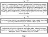
- Embodiment 2 of the present invention provides a signal receiving method. Specifically, as shown in FIG. 4, FIG. 4 is a schematic flowchart of a signal receiving method according to Embodiment 2 of the present invention.
- the signal receiving method may specifically include the following steps:
- the digital signal may be despread based on the N spreading codes used by the signal transmit device for amplitude spread spectrum modulation, so as to improve accuracy of data recovery and receiving.
- the signal may be despread in a manner of multiplying each of the N spreading codes by the digital signal, to obtain the N despread signals. Details are not described herein.
- the N spreading codes may be mutually orthogonal bipolar binary spread spectrum sequences.
- each of the N spreading codes may be a real number sequence such as a Walsh code or an OVSF code.
- each spreading code may be a sequence code generated by scrambling the real number sequence such as the Walsh code or the OVSF code based on a specified pseudo-random sequence code, or the like. This is not limited in this embodiment of the present invention.
- the method may further include: performing adaptive filtering on each of the N data signals, to obtain N data signals obtained after the adaptive filtering, so as to improve accuracy of data recovery and receiving.
- the method may further include: performing carrier phase retrieval on each of the N data signals obtained after the adaptive filtering, to obtain N data signals obtained after the carrier phase retrieval, so as to further improve accuracy of data recovery and receiving.
- the method may further include: performing dispersion compensation on the digital signal, to eliminate impact of dispersion on the digital signal, and further improve accuracy of data recovery and receiving.
- Embodiment 2 of the present invention may be usually performed by a corresponding signal receiving device. Details are not described in this embodiment of the present invention.
- Embodiment 3 of the present invention provides a signal transmit device.
- FIG. 5 is a schematic structural diagram of a signal transmit device according to Embodiment 3 of the present invention. It can be learned from FIG. 5 that the signal transmit device may include a light source 51, a deserializer 52, a first splitting device 53, a first combining device 54, and N spread spectrum modulation devices 55.
- a value of N is a positive integer not less than 2.
- the light source 51 may be configured to: generate a single-wavelength optical carrier, and output the single-wavelength optical carrier to the first splitting device 53.
- the deserializer 52 may be configured to: deserialize a received high-speed data signal into N low-speed data signals, and output the N low-speed data signals to the N spread spectrum modulation devices 55.
- the N low-speed data signals are in a one-to-one correspondence with the N spread spectrum modulation devices 55.
- the first splitting device 53 may be configured to: split the single-wavelength optical carrier generated by the light source 51 into N subcarriers with a same wavelength, and output the N subcarriers to the N spread spectrum modulation devices 55, The N subcarriers are in a one-to-one correspondence with the N spread spectrum modulation devices 55.
- Each of the N spread spectrum modulation devices 55 may be configured to: respectively perform, according to a low-speed data signal corresponding to the spread spectrum modulation device 55 and a spreading code in N spreading codes that is corresponding to the spread spectrum modulation device 55, data modulation and amplitude spread spectrum modulation on a subcarrier corresponding to the spread spectrum modulation device 55, to obtain a spread spectrum modulation signal corresponding to the spread spectrum modulation device 55, and output the spread spectrum modulation signal to the first combining device 54.
- the N spreading codes are in a one-to-one correspondence with the N spread spectrum modulation devices.
- the first combining device 54 may be configured to combine N spread spectrum modulation signals received from the N spread spectrum modulation devices 55 into a combined signal for outputting.
- the generated single-wavelength optical carrier may be split into the N subcarriers with a same wavelength by using the splitting device, corresponding data modulation and corresponding amplitude spread spectrum modulation are performed on the N subcarriers by using the N spreading codes and the N low-speed data signals obtained by deserializing the received high-speed data signal, to obtain the N spread spectrum modulation signals, and the N spread spectrum modulation signals are combined and output.
- the data signal may be processed by using a low-speed DAC with a high ENOB and another electrical device with a low bandwidth, so as to effectively reduce quantization noise of the ADC and electrical noise of the another electrical device, and improve system performance of higher-order QAM modulation.
- a multicarrier generation apparatus and a demultiplexer that have a relatively complex structure do not need to be used for optical carrier splitting, and spectrum spreading does not need to be performed in a phase modulation manner in which a plurality of delay units or controllable phase units are required. Therefore, system reliability is improved, and problems such as relatively high costs and a relatively great difficulty in implementation that exist in an existing manner of improving QAM system reliability are effectively resolved.
- the light source 51 may be any light source that can generate a single-wavelength optical carrier, for example, a single-wavelength LED light source or a laser light source.
- the first splitting device 53 may be any splitting device that can split a single-wavelength optical carrier into a plurality of subcarriers with a same wavelength, for example, a coupler or a splitter.
- the first combining device 54 may be any combining device that can combine N spread spectrum modulation signals into a spread spectrum modulation signal, for example a coupler or a combiner. This is not limited in this embodiment of the present invention.
- any of the N spread spectrum modulation devices 55 may be specifically configured to: perform, according to a low-speed data signal corresponding to the spread spectrum modulation device 55, data modulation on a subcarrier corresponding to the spread spectrum modulation device55, to obtain a data modulation signal, perform amplitude spread spectrum modulation on the data modulation signal according to a spreading code corresponding to the spread spectrum modulation device 55, to obtain a spread spectrum modulation signal corresponding to the spread spectrum modulation device 55, and output the spread spectrum modulation signal to the first combining device 54.
- any of the N spread spectrum modulation devices 55 may be further specifically configured to: perform, according to a spreading code corresponding to the spread spectrum modulation device 55, amplitude spread spectrum modulation on a subcarrier corresponding to the spread spectrum modulation device 55, to obtain a spread spectrum signal, perform data modulation on the spread spectrum signal according to a low-speed data signal corresponding to the spread spectrum modulation device 55, to obtain a spread spectrum modulation signal corresponding to the spread spectrum modulation device 55, and output the spread spectrum modulation signal to the first combining device 54.
- data modulation may be performed on the subcarrier before amplitude spread spectrum modulation, or amplitude spread spectrum modulation may be performed on the subcarrier before data modulation, so as to improve data processing flexibility. Details are not described herein.
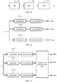
- any spread spectrum modulation device 55 may specifically include a modulator and a spectrum spreader.
- the modulator may be configured to: perform, according to a low-speed data signal corresponding to the spread spectrum modulation device 55, data modulation on a subcarrier corresponding to the spread spectrum modulation device 55, and output a data modulation signal to the spectrum spreader.
- the spectrum spreader performs amplitude spread spectrum modulation on the data modulation signal according to a spreading code corresponding to the spread spectrum modulation device 55, and outputs a spread spectrum modulation signal to the first combining device 54 (details may be shown in FIG. 6 ).
- the modulator may be configured to: receive a spread spectrum signal obtained after the spectrum spreader performs, according to a spreading code corresponding to the spread spectrum modulation device 55, amplitude spread spectrum modulation on a subcarrier corresponding to the spread spectrum modulation device 55, perform data modulation on the spread spectrum signal according to a low-speed data signal corresponding to the spread spectrum modulation device 55, and output a spread spectrum modulation signal to the first combining device 54 (details may be shown in FIG. 7 ).
- the spectrum spreader may be configured to: receive a data modulation signal obtained after the modulator performs, according to a low-speed data signal corresponding to the spread spectrum modulation device 55, data modulation on a subcarrier corresponding to the spread spectrum modulation device 55, perform amplitude spread spectrum modulation on the data modulation signal according to a spreading code corresponding to the spread spectrum modulation device 55, and output a spread spectrum modulation signal to the first combining device 54 (details may be shown in FIG. 6 ).
- the spectrum spreader may be configured to: perform, according to a spreading code corresponding to the spread spectrum modulation device 55, amplitude spread spectrum modulation on a subcarrier corresponding to the spread spectrum modulation device 55, and output a spread spectrum signal to the modulator.
- the modulator performs data modulation on the spread spectrum signal according to a low-speed data signal corresponding to the spread spectrum modulation device 55, and output a spread spectrum modulation signal to the first combining device 54 (details may be shown in FIG. 7 ).
- Signals XI, XQ, YI, and YQ shown in FIG. 6 or FIG. 7 are low-speed data signals obtained after the deserializer 52 deserializes the high-speed data signal.
- Code is a corresponding spreading code. Details are not described in this embodiment of the present invention.
- a modulator included in each spread spectrum modulation device 55 may be PDM-QAM, single-polarization QAM, PAM, or the like. Certainly, the modulator may be any other modulation device that can implement corresponding data modulation.
- a spectrum spreader included in each spread spectrum modulation device 55 may be an MZM or the like. Certainly, the spectrum spreader may be any other spread spectrum device that can implement corresponding amplitude spread spectrum modulation (implement spectrum spreading by performing amplitude spread spectrum modulation on a subcarrier). Details are not described in this embodiment of the present invention.
- data modulation and spectrum spreading may be performed on any subcarrier that is used as a whole, to obtain a spread spectrum modulation signal.
- the subcarrier may be split into two tributary subcarriers for which data modulation and spectrum spreading are separately performed, to obtain two tributary spread spectrum modulation signals, and the two tributary spread spectrum modulation signals are combined and output, to obtain a spread spectrum modulation signal corresponding to the subcarrier.
- any of the N spread spectrum modulation devices 55 may be further specifically configured to:
- the spread spectrum modulation device 55 may be further specifically configured to: perform amplitude spread spectrum modulation on the first tributary subcarrier according to a spreading code corresponding to the spread spectrum modulation device 55, to obtain a first tributary spread spectrum signal, and perform data modulation on the first tributary spread spectrum signal according to a low-speed data signal corresponding to the spread spectrum modulation device 55, to obtain a first tributary spread spectrum modulation signal; perform amplitude spread spectrum modulation on the second tributary subcarrier according to a spreading code that is obtained after the phase reversion and that
- a sequence of performing data modulation and amplitude spread spectrum modulation on each tributary subcarrier may flexibly change. This is not limited in this embodiment of the present invention.
- the spread spectrum modulation device 55 may include a second splitting device, a phase shifter, a first dual-electrode modulator, a second dual-electrode modulator, and a second combining device.
- the second splitting device may be configured to split a subcarrier corresponding to the spread spectrum modulation device 55 into a first tributary subcarrier and a second tributary subcarrier.
- the phase shifter may be configured to separately perform phase shifting on the first tributary subcarrier and the second tributary subcarrier, so that a phase difference between the two tributary subcarriers is a specified value, for example, may be 180 degrees.
- the first dual-electrode modulator may be configured to: perform data modulation on the first tributary subcarrier according to a low-speed data signal corresponding to the spread spectrum modulation device 55, to obtain a first tributary data modulation signal, and perform amplitude spread spectrum modulation on the first tributary data modulation signal according to a spreading code corresponding to the spread spectrum modulation device 55, to obtain a first tributary spread spectrum modulation signal (details may be shown in FIG. 8 ).
- the first dual-electrode modulator may be configured to: perform amplitude spread spectrum modulation on the first tributary subcarrier according to a spreading code corresponding to the spread spectrum modulation device 55, to obtain a first tributary spread spectrum signal, and perform data modulation on the first tributary spread spectrum signal according to a low-speed data signal corresponding to the spread spectrum modulation device 55, to obtain a first tributary spread spectrum modulation signal (details may be shown in FIG. 9 ).
- the second dual-electrode modulator may be configured to: perform data modulation on the second tributary subcarrier according to a low-speed data signal that is obtained after the phase reversion and that is corresponding to the spread spectrum modulation device 55, to obtain a second tributary data modulation signal, and perform amplitude spread spectrum modulation on the second tributary data modulation signal according to a spreading code that is obtained after the phase reversion and that is corresponding to the spread spectrum modulation device 55, to obtain a second tributary spread spectrum modulation signal (details may be shown in FIG. 8 ).
- the second dual-electrode modulator may be configured to: perform amplitude spread spectrum modulation on the second tributary subcarrier according to a spreading code that is obtained after the phase reversion and that is corresponding to the spread spectrum modulation device 55, to obtain a second tributary spread spectrum signal, and perform data modulation on the second tributary spread spectrum signal according to a low-speed data signal that is obtained after the phase reversion and that is corresponding to the spread spectrum modulation device 55, to obtain a second tributary spread spectrum modulation signal (details may be shown in FIG. 9 ).
- the second combining device may be configured to: combine the first tributary spread spectrum modulation signal and the second tributary spread spectrum modulation signal, to obtain a spread spectrum modulation signal corresponding to the spread spectrum modulation device 55, and output the spread spectrum modulation signal to the first combining device 54.
- Signals XI, XQ, YI, and YQ shown in FIG. 8 or FIG. 9 are low-speed data signals obtained after the deserializer 52 deserializes the high-speed data signal.
- Code is a corresponding spreading code. Details are not described in this embodiment of the present invention.
- the second splitting device may be any splitting device that can split a corresponding subcarrier into two tributary subcarriers, for example, a coupler or a splitter
- the second combining device may be any combining device that can combine a first tributary spread spectrum modulation signal and a second tributary spread spectrum modulation signal into a spread spectrum modulation signal, for example, a coupler or a combiner.
- phase shifter may be any phase shifting device that can perform phase shifting on two tributary subcarriers of a subcarrier, so that the two tributary subcarriers have a specified phase difference (for example, the phase difference may be 180 degrees).
- a phase of a first tributary subcarrier of the two tributary subcarriers may be kept unchanged, and only a phase of a second tributary subcarrier of the two tributary subcarriers is shift by 180 degrees or -180 degrees; or a phase of a second tributary subcarrier of the two tributary subcarriers may be kept unchanged, and only a phase of a first tributary subcarrier of the two tributary subcarriers is shift by 180 degrees or -180 degrees; or certainly, a phase of a first tributary subcarrier of the two tributary subcarriers may be shift by 90 degrees, and a phase of a second tributary subcarrier is shift by -90 degrees; or a phase of a first tributary subcarrier of the two tributary subcarriers may be shift by -90 degrees, and
- first dual-electrode modulator and the second dual-electrode modulator may be any modulator that can perform both data modulation and amplitude modulation on a carrier by using a data signal and a spreading code, for example, an EAM.
- a sequence of performing data modulation and amplitude modulation on the carrier by the first dual-electrode modulator and the second dual-electrode modulator may flexibly change. Signals (a data signal, a spreading code, and the like) received through two electrodes used to receive corresponding signals need to interchange with each other. Details are not described in this embodiment of the present invention.
- a working procedure of the spread spectrum modulation device 55 having a dual-electrode modulator is specifically described below by using data modulation and amplitude spread spectrum modulation performed on a subcarrier as an example.
- an expression of a first tributary data modulation signal obtained after data modulation is performed on the first tributary subcarrier of the subcarrier by using a first low-speed data signal corresponding to the subcarrier may be ( Data 1 + P 1) e j ⁇ t , and e j ⁇ t represents the subcarrier.
- an expression of a first tributary spread spectrum modulation signal obtained after amplitude spread spectrum modulation is performed on the first tributary data modulation signal by using a first spreading code corresponding to the subcarrier may be ( Code 1 + P 2)( Data 1 + P 1) e j ⁇ t .
- an expression of a second tributary spread spectrum modulation signal obtained after corresponding data modulation and corresponding amplitude spread spectrum modulation are performed on a second tributary subcarrier of the subcarrier by using a first low-speed data signal obtained after the phase reversion and a first spreading code obtained after the phase reversion may be (- Code 1 + P 2)(- Data 1 + P 1) e j ⁇ t . Afterwards, the first tributary spread spectrum modulation signal and the second tributary spread spectrum modulation signal are combined, to obtain a spread spectrum modulation signal corresponding to the subcarrier.
- An expression of the spread spectrum modulation signal may be ( Code 1 ⁇ Data 1 + P 1 ⁇ P 2) e j ⁇ t , and P 1 ⁇ P 2 is residual carrier power after data modulation and amplitude spread spectrum modulation. It can be learned that the combined spread spectrum modulation signal is a correct spread spectrum modulation signal. This further indicates that correct data modulation and correct spectrum spreading are implemented.
- the N spreading codes may be mutually orthogonal bipolar binary spread spectrum sequences.
- each of the N spreading codes may be a real number sequence such as a Walsh code or an OVSF code.
- each spreading code may be a sequence code generated by scrambling the real number sequence such as the Walsh code or the OVSF code based on a specified pseudo-random sequence code, or the like. This is not limited in this embodiment of the present invention.
- the signal transmit device may split the single-wavelength optical carrier transmitted by the light source into the N subcarriers with a same wavelength by using the first splitting device, and perform, by using the N spread spectrum modulation devices, corresponding data modulation and corresponding amplitude spread spectrum modulation on the N subcarriers by using the specified N spreading codes and the N low-speed data signals obtained after the deserializer deserializes the received high-speed data signal, to obtain the N spread spectrum modulation signals, and combine and output the N spread spectrum modulation signals by using the first combining device.
- the data signal may be processed by using a low-speed DAC with a high ENOB and another electrical device with a low bandwidth, so as to effectively reduce quantization noise of the ADC and electrical noise of the another electrical device, and improve system performance of higher-order QAM modulation.
- a multicarrier generation apparatus and a demultiplexer that have a relatively complex structure do not need to be used for optical carrier splitting, and spectrum spreading does not need to be performed in a phase modulation manner in which a plurality of delay units or controllable phase units are required. Therefore, system reliability is improved, and problems such as relatively high costs and a relatively great difficulty in implementation that exist in an existing manner of improving QAM system reliability are effectively resolved.
- Embodiment 4 of the present invention provides a signal receiving device.
- FIG. 10 is a schematic structural diagram of a signal receiving device according to Embodiment 4 of the present invention. It can be learned from FIG. 10 that the signal receiving device may include an OEC 101, an ADC 102, and a DSP 103.
- the OEC 101 may be configured to: receive a signal transmitted by a signal transmit device, convert the received signal into an electrical signal, and output the electrical signal to the ADC 102.
- the signal transmit device splits, by using a splitting device, a single-wavelength optical carrier generated by a light source into N subcarriers with a same wavelength, performs data modulation and amplitude spread spectrum modulation on the N subcarriers based on N low-speed data signals and N spreading codes, to obtain N spread spectrum modulation signals, and the signal transmit device combines the N spread spectrum modulation signals, to obtain the signal.
- the ADC 102 may be configured to: receive the electrical signal output by the OEC 101, convert the electrical signal into a digital signal, and output the digital signal to the DSP.
- the DSP 103 may be configured to: receive the digital signal output by the ADC 102, despread the digital signal based on the N spreading codes, to obtain N despread signals, and perform low-pass filtering on each of the N despread signals, to obtain N data signals.
- N is a positive integer not less than 2.
- the digital signal may be despread based on the N spreading codes used by the signal transmit device for amplitude spread spectrum modulation, so as to improve accuracy of data recovery and receiving.
- the N spreading codes may be mutually orthogonal bipolar binary spread spectrum sequences.
- each of the N spreading codes may be a real number sequence such as a Walsh code or an OVSF code.
- each spreading code may be a sequence code generated by scrambling the real number sequence such as the Walsh code or the OVSF code based on a specified pseudo-random sequence code, or the like. Details are not described herein.
- the DSP 103 may include N despreaders that are in a one-to-one correspondence with the N spreading codes, and N LPFs (Low-Pass Filter, low-pass filter) that are in a one-to-one correspondence with the N despreaders.
- N LPFs Low-Pass Filter, low-pass filter
- Each of the N despreaders may be configured to: despread the received digital signal according to a spreading code in the N spreading codes that is corresponding to the despreader, to obtain a despread signal, and output the despread signal to an LPF corresponding to the despreader.
- Each of the N LPFs may be configured to: receive a despread signal output by a corresponding despreader, and perform low-pass filtering on the received despread signal, to obtain a data signal.
- the despreader may be any despreading device that can despread a spread spectrum signal, for example, a multiplier. This is not limited in this embodiment of the present invention. Specifically, when the despreader is the multiplier, the despreader may despread the spread spectrum signal by multiplying the received signal by a corresponding spreading code, so as to improve accuracy of data recovery and receiving.
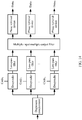
- the DSP 103 in the signal receiving device may further implement multi-access crosstalk elimination and data recovery by using an implementation structure shown in FIG. 12 .
- the DSP may further include a multiple-input multiple-output filter.
- the multiple-input multiple-output filter may be configured to perform adaptive filtering on each of the N data signals (that is, data signals output by the N LPFs), to obtain N data signals obtained after the adaptive filtering, so as to improve accuracy of data recovery and receiving.
- the multiple-input multiple-output filter may be any filtering device that can perform adaptive filtering on a plurality of input signals to eliminate multi-access crosstalk, for example, a MIMO FIR (multiple-input multiple-output finite impulse response) filter.
- MIMO FIR multiple-input multiple-output finite impulse response
- a coefficient of the MIMO FIR filter may be obtained through calculation by using an algorithm such as a CMA (Constant Modulus Algorithm, Constant Modulus Algorithm) or an LMS (Least Mean Square, least mean square). Details are not described herein.
- the DSP may further include N phase retrieval devices that are in a one-to-one correspondence with the N data signals obtained after the adaptive filtering.
- Each of the N phase retrieval devices may be configured to perform carrier phase retrieval on a data signal that is obtained after the adaptive filtering and that is corresponding to the phase retrieval device, to obtain a data signal obtained after the carrier phase retrieval, so as to improve accuracy of data recovery and receiving.
- the DSP may further include a dispersion compensator, that is, a CDC (chromatic dispersion compensation).
- a dispersion compensator that is, a CDC (chromatic dispersion compensation).
- the dispersion compensator may be configured to: perform dispersion compensation on the received digital signal before the received digital signal is despread, and output a digital signal obtained after the dispersion compensation to the N despreaders, to eliminate impact of dispersion on the digital signal, and improve accuracy of data recovery and receiving.
- Embodiment 5 of the present invention provides a signal transmission system.
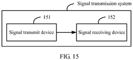
- the signal transmission system may include a signal transmit device 151 and a signal receiving device 152.
- the signal transmit device 151 is configured to: generate a single-wavelength optical carrier; split the single-wavelength optical carrier into N subcarriers with a same wavelength based on a splitting device; perform data modulation and amplitude spread spectrum modulation on the N subcarriers according to N low-speed data signals and N spreading codes, to obtain N spread spectrum modulation signals; combine the obtained N spread spectrum modulation signals into a combined signal; and output the combined signal to the signal receiving device 152.
- a value of N is a positive integer not less than 2, the N spreading codes are in a one-to-one correspondence with the N subcarriers, the N low-speed data signals are in a one-to-one correspondence with the N subcarriers, and the N low-speed data signals are obtained by deserializing a received high-speed data signal.
- the signal receiving device 152 is configured to: receive a signal transmitted by the signal transmit device 151; perform optical-to-electrical conversion processing and analog-to-digital conversion processing on the received signal, to obtain a digital signal; despread the digital signal based on the N spreading codes, to obtain N despread signals; and perform low-pass filtering on each of the N despread signals, to obtain N data signals.
- the embodiments of the present invention may be provided as a method, an apparatus (device), or a computer program product. Therefore, the present invention may use a form of hardware only embodiments, software only embodiments, or embodiments with a combination of software and hardware. Moreover, the present invention may use a form of a computer program product that is implemented on one or more computer-usable storage media (including but not limited to a disk memory, a CD-ROM, an optical memory, and the like) that include computer-usable program code.
- computer-usable storage media including but not limited to a disk memory, a CD-ROM, an optical memory, and the like
- These computer program instructions may be provided for a general-purpose computer, a dedicated computer, an embedded processor, or a processor of any other programmable data processing device to generate a machine, so that the instructions executed by a computer or a processor of any other programmable data processing device generate an apparatus for implementing a specific function in one or more processes in the flowcharts and/or in one or more blocks in the block diagrams.
- These computer program instructions may also be stored in a computer readable memory that can instruct the computer or any other programmable data processing device to work in a specific manner, so that the instructions stored in the computer readable memory generate an artifact that includes an instruction apparatus.
- the instruction apparatus implements a specific function in one or more processes in the flowcharts and/or in one or more blocks in the block diagrams.
- These computer program instructions may also be loaded onto a computer or another programmable data processing device, so that a series of operations and steps are performed on the computer or the another programmable device, thereby generating computer-implemented processing. Therefore, the instructions executed on the computer or the another programmable device provide steps for implementing a specific function in one or more processes in the flowcharts and/or in one or more blocks in the block diagrams.
Landscapes
- Engineering & Computer Science (AREA)
- Computer Networks & Wireless Communication (AREA)
- Signal Processing (AREA)
- Physics & Mathematics (AREA)
- Electromagnetism (AREA)
- Optics & Photonics (AREA)
- Optical Communication System (AREA)
Claims (7)
- Signalübertragungsverfahren, das Folgendes umfasst:Erzeugen (301) eines optischen Einzelwellenlängenträgers;Teilen (302) des optischen Einzelwellenlängenträgers in N Unterträger mit gleicher Wellenlänge basierend auf einer Teilungsvorrichtung, wobei ein Wert von N eine positive ganze Zahl nicht kleiner als 2 ist;Durchführen (303) einer Datenmodulation und einer Amplitudenspreizspektrumsmodulation an den N Unterträgern gemäß N Niedergeschwindigkeitsdatensignalen und N Spreizcodes, um N Spreizspektrumsmodulationssignale zu erhalten, wobei die N Spreizcodes in einer eineindeutigen Entsprechung zu den N Unterträgern stehen, die N Niedergeschwindigkeitsdatensignale in einer eineindeutigen Entsprechung zu den N Unterträgern stehen und die N Niedergeschwindigkeitsdatensignale durch Deserialisieren eines empfangenen Hochgeschwindigkeitsdatensignals erhalten werden; undKombinieren (304) der erhaltenen N Spreizspektrumsmodulationssignale zu einem kombinierten Signal zur Ausgabe,wobei das Durchführen (303) einer Datenmodulation und einer Amplitudenspreizspektrumsmodulation an den N Unterträgern gemäß N Niedergeschwindigkeitsdatensignalen und N Spreizcodes, um N Spreizspektrumsmodulationssignale zu erhalten, Folgendes umfasst:Teilen jedes der N Unterträger in einen ersten Tributärunterträger und einen zweiten Tributärunterträger und separates Durchführen einer Phasenverschiebung an dem ersten Tributärunterträger und dem zweiten Tributärunterträger;Durchführen einer Datenmodulation an dem ersten Tributärunterträger gemäß einem dem Unterträger entsprechenden Niedergeschwindigkeitsdatensignal, um ein erstes Tributärdatenmodulationssignal zu erhalten, und Durchführen einer Amplitudenspreizspektrumsmodulation an dem ersten Tributärdatenmodulationssignal gemäß einem dem Unterträger entsprechenden Spreizcode, um ein erstes Tributärspreizspektrumsmodulationssignal zu erhalten; und Durchführen einer Datenmodulation an dem zweiten Tributärunterträger gemäß einem Niedergeschwindigkeitsdatensignal, das nach einer Phasenumkehr erhalten wird und das dem Unterträger entspricht, um ein zweites Tributärdatenmodulationssignal zu erhalten, und Durchführen einer Amplitudenspreizspektrumsmodulation an dem zweiten Tributärdatenmodulationssignal gemäß einem Spreizcode, der nach der Phasenumkehr erhalten wird und der dem Unterträger entspricht, um ein zweites Tributärspreizspektrumsmodulationssignal zu erhalten; undKombinieren des ersten Tributärspreizspektrumsmodulationssignals und des zweiten Tributärspreizspektrumsmodulationssignals, um ein dem Unterträger entsprechendes Spreizspektrumsmodulationssignal zu erhalten,
oderTeilen jedes der N Unterträger in einen ersten Tributärunterträger und einen zweiten Tributärunterträger und separates Durchführen einer Phasenverschiebung an dem ersten Tributärunterträger und dem zweiten Tributärunterträger;Durchführen einer Amplitudenspreizspektrumsmodulation an dem ersten Tributärunterträger gemäß einem dem Unterträger entsprechenden Spreizcode, um ein erstes Tributärspreizspektrumssignal zu erhalten, und Durchführen einer Datenmodulation an dem ersten Tributärspreizspektrumssignal gemäß einem dem Unterträger entsprechenden Niedergeschwindigkeitsdatensignal, um ein erstes Tributärspreizspektrumsmodulationssignal zu erhalten; und Durchführen einer Amplitudenspreizspektrumsmodulation an dem zweiten Tributärunterträger gemäß einem Spreizcode, der nach einer Phasenumkehr erhalten wird und der dem Unterträger entspricht, um ein zweites Tributärspreizspektrumssignal zu erhalten, und Durchführen einer Datenmodulation an dem zweiten Tributärspreizspektrumssignal gemäß einem Niedergeschwindigkeitsdatensignal, das nach der Phasenumkehr erhalten wird und das dem Unterträger entspricht, um ein zweites Tributärspreizspektrumsmodulationssignal zu erhalten; undKombinieren des ersten Tributärspreizspektrumsmodulationssignals und des zweiten Tributärspreizspektrumsmodulationssignals, um ein dem Unterträger entsprechendes Spreizspektrumsmodulationssignal zu erhalten. - Signalübertragungsverfahren, das Folgendes umfasst:Empfangen (401) eines durch eine Signalübertragungsvorrichtung übertragenen Signals, wobei das Signal von der Übertragungsvorrichtung erzeugt wird durch Teilen eines optischen Einzelwellenlängenträgers in N Unterträger mit gleicher Wellenlänge, Durchführen einer Datenmodulation und einer Amplitudenspreizspektrumsmodulation an den N Unterträgern basierend auf N Niedergeschwindigkeitsdatensignalen und N Spreizcodes, um N Spreizspektrumsmodulationssignale zu erhalten, und Kombinieren der N Spreizspektrumsmodulationssignale;Durchführen (402) einer Optisch-zu-Elektrisch-Umsetzungsverarbeitung und einer Analog-zu-Digital-Umsetzungsverarbeitung an dem empfangenen Signal, um ein digitales Signal zu erhalten; undEntspreizen (403) des digitalen Signals basierend auf den N Spreizcodes, um N entspreizte Signale zu erhalten, und Durchführen einer Tiefpassfilterung an jedem der N entspreizten Signale, um N Datensignale zu erhalten, wobei N eine positive ganze Zahl nicht kleiner als 2 ist,wobei das Durchführen einer Datenmodulation und einer Amplitudenspreizspektrumsmodulation an den N Unterträgern basierend auf N Niedergeschwindigkeitsdatensignalen und N Spreizcodes, um N Spreizspektrumsmodulationssignale zu erhalten, Folgendes umfasst:Teilen jedes der N Unterträger in einen ersten Tributärunterträger und einen zweiten Tributärunterträger und separates Durchführen einer Phasenverschiebung an dem ersten Tributärunterträger und dem zweiten Tributärunterträger;Durchführen einer Datenmodulation an dem ersten Tributärunterträger gemäß einem dem Unterträger entsprechenden Niedergeschwindigkeitsdatensignal, um ein erstes Tributärdatenmodulationssignal zu erhalten, und Durchführen einer Amplitudenspreizspektrumsmodulation an dem ersten Tributärdatenmodulationssignal gemäß einem dem Unterträger entsprechenden Spreizcode, um ein erstes Tributärspreizspektrumsmodulationssignal zu erhalten; und Durchführen einer Datenmodulation an dem zweiten Tributärunterträger gemäß einem Niedergeschwindigkeitsdatensignal, das nach einer Phasenumkehr erhalten wird und das dem Unterträger entspricht, um ein zweites Tributärdatenmodulationssignal zu erhalten, und Durchführen einer Amplitudenspreizspektrumsmodulation an dem zweiten Tributärdatenmodulationssignal gemäß einem Spreizcode, der nach der Phasenumkehr erhalten wird und der dem Unterträger entspricht, um ein zweites Tributärspreizspektrumsmodulationssignal zu erhalten; undKombinieren des ersten Tributärspreizspektrumsmodulationssignals und des zweiten Tributärspreizspektrumsmodulationssignals, um ein dem Unterträger entsprechendes Spreizspektrumsmodulationssignal zu erhalten,
oderTeilen jedes der N Unterträger in einen ersten Tributärunterträger und einen zweiten Tributärunterträger und separates Durchführen einer Phasenverschiebung an dem ersten Tributärunterträger und dem zweiten Tributärunterträger;Durchführen einer Amplitudenspreizspektrumsmodulation an dem ersten Tributärunterträger gemäß einem dem Unterträger entsprechenden Spreizcode, um ein erstes Tributärspreizspektrumssignal zu erhalten, und Durchführen einer Datenmodulation an dem ersten Tributärspreizspektrumssignal gemäß einem dem Unterträger entsprechenden Niedergeschwindigkeitsdatensignal, um ein erstes Tributärspreizspektrumsmodulationssignal zu erhalten; und Durchführen einer Amplitudenspreizspektrumsmodulation an dem zweiten Tributärunterträger gemäß einem Spreizcode, der nach einer Phasenumkehr erhalten wird und der dem Unterträger entspricht, um ein zweites Tributärspreizspektrumssignal zu erhalten,und Durchführen einer Datenmodulation an dem zweiten Tributärspreizspektrumssignal gemäß einem Niedergeschwindigkeitsdatensignal, das nach der Phasenumkehr erhalten wird und das dem Unterträger entspricht, um ein zweites Tributärspreizspektrumsmodulationssignal zu erhalten; undKombinieren des ersten Tributärspreizspektrumsmodulationssignals und des zweiten Tributärspreizspektrumsmodulationssignals, um ein dem Unterträger entsprechendes Spreizspektrumsmodulationssignal zu erhalten. - Signalübertragungsverfahren nach Anspruch 2, wobei das Verfahren ferner Folgendes umfasst:
Durchführen einer adaptiven Filterung an jedem der N Datensignale, um nach der adaptiven Filterung erhaltene N Datensignale zu erhalten. - Signalübertragungsvorrichtung (151), wobei die Vorrichtung (151) eine Lichtquelle (51), einen Deserialisierer (52), eine erste Teilungsvorrichtung (53), eine erste Kombiniervorrichtung (54) und N Spreizspektrumsmodulationsvorrichtungen (55) umfasst; und wobei ein Wert von N eine positive ganze Zahl nicht kleiner als 2 ist, wobei
die Lichtquelle (51) ausgelegt ist zum: Erzeugen eines optischen Einzelwellenlängenträgers und Ausgeben des optischen Einzelwellenlängenträgers an die erste Teilungsvorrichtung (52);
der Deserialisierer (52) ausgelegt ist zum: Deserialisieren eines empfangenen Hochgeschwindigkeitsdatensignals zu N Niedergeschwindigkeitsdatensignalen und Ausgeben der N Niedergeschwindigkeitsdatensignale an die N Spreizspektrumsmodulationsvorrichtungen (55), wobei die N Niedergeschwindigkeitsdatensignale in einer eineindeutigen Entsprechung zu den N Spreizspektrumsmodulationsvorrichtungen (55) stehen;
die erste Teilungsvorrichtung (52) ausgelegt ist zum: Teilen des durch die Lichtquelle erzeugten optischen Einzelwellenlängenträgers in N Unterträger mit gleicher Wellenlänge und Ausgeben der N Unterträger an die N Spreizspektrumsmodulationsvorrichtungen (55), wobei die N Unterträger in einer eineindeutigen Entsprechung zu den N Spreizspektrumsmodulationsvorrichtungen (55) stehen;
jede der N Spreizspektrumsmodulationsvorrichtungen (55) ausgelegt ist zum:jeweiligen Durchführen, gemäß einem der Spreizspektrumsmodulationsvorrichtung (55) entsprechenden Niedergeschwindigkeitsdatensignal und einem Spreizcode in N Spreizcodes, der der Spreizspektrumsmodulationsvorrichtung (55) entspricht, einer Datenmodulation und einer Amplitudenspreizspektrumsmodulation an einem der Spreizspektrumsmodulationsvorrichtung (55) entsprechenden Unterträger, um ein der Spreizspektrumsmodulationsvorrichtung (55) entsprechendes Spreizspektrumsmodulationssignal zu erhalten, und Ausgeben des Spreizspektrumsmodulationssignals an die erste Kombiniervorrichtung (54), wobei die N Spreizcodes in einer eineindeutigen Entsprechung zu den N Spreizspektrumsmodulationsvorrichtungen (55) stehen; unddie erste Kombiniervorrichtung (54) ausgelegt ist zum Kombinieren von von den N Spreizspektrumsmodulationsvorrichtungen (55) empfangenen N Spreizspektrumsmodulationssignale zu einem kombinierten Signal zur Ausgabe,wobei jede der N Spreizspektrumsmodulationsvorrichtungen (55) insbesondere zu Folgendem ausgelegt ist:Teilen eines der Spreizspektrumsmodulationsvorrichtung entsprechenden Unterträgers in einen ersten Tributärunterträger und einen zweiten Tributärunterträger und separates Durchführen einer Phasenverschiebung an dem ersten Tributärunterträger und dem zweiten Tributärunterträger; undDurchführen einer Datenmodulation an dem ersten Tributärunterträger gemäß einem der Spreizspektrumsmodulationsvorrichtung (55) entsprechenden Niedergeschwindigkeitsdatensignal, um ein erstes Tributärdatenmodulationssignal zu erhalten, und Durchführen einer Amplitudenspreizspektrumsmodulation an dem ersten Tributärdatenmodulationssignal gemäß einem der Spreizspektrumsmodulationsvorrichtung (55) entsprechenden Spreizcode, um ein erstes Tributärspreizspektrumsmodulationssignal zu erhalten; Durchführen einer Datenmodulation an dem zweiten Tributärunterträger gemäß einem Niedergeschwindigkeitsdatensignal, das nach einer Phasenumkehr erhalten wird und das der Spreizspektrumsmodulationsvorrichtung (55) entspricht, um ein zweites Tributärdatenmodulationssignal zu erhalten, und Durchführen einer Amplitudenspreizspektrumsmodulation an dem zweiten Tributärdatenmodulationssignal gemäß einem Spreizcode, der nach der Phasenumkehr erhalten wird und der der Spreizspektrumsmodulationsvorrichtung (55) entspricht, um ein zweites Tributärspreizspektrumsmodulationssignal zu erhalten; und Kombinieren des ersten Tributärspreizspektrumsmodulationssignals und des zweiten Tributärspreizspektrumsmodulationssignals, um ein der Spreizspektrumsmodulationsvorrichtung (55) entsprechendes Spreizspektrumsmodulationssignal zu erhalten, und Ausgeben des Spreizspektrumsmodulationssignals an die erste Kombiniervorrichtung (54),
oderTeilen eines der Spreizspektrumsmodulationsvorrichtung entsprechenden Unterträgers in einen ersten Tributärunterträger und einen zweiten Tributärunterträger und separates Durchführen einer Phasenverschiebung an dem ersten Tributärunterträger und dem zweiten Tributärunterträger; undDurchführen einer Amplitudenspreizspektrumsmodulation an dem ersten Tributärunterträger gemäß einem der Spreizspektrumsmodulationsvorrichtung (55) entsprechenden Spreizcode, um ein erstes Tributärspreizspektrumssignal zu erhalten, und Durchführen einer Datenmodulation an dem ersten Tributärspreizspektrumssignal gemäß einem der Spreizspektrumsmodulationsvorrichtung (55) entsprechenden Niedergeschwindigkeitsdatensignal, um ein erstes Tributärspreizspektrumsmodulationssignal zu erhalten; und Durchführen einer Amplitudenspreizspektrumsmodulation an dem zweiten Tributärunterträger gemäß einem Spreizcode, der nach einer Phasenumkehr erhalten wird und der der Spreizspektrumsmodulationsvorrichtung (55) entspricht, um ein zweites Tributärspreizspektrumssignal zu erhalten, und Durchführen einer Datenmodulation an dem zweiten Tributärspreizspektrumssignal gemäß einem Niedergeschwindigkeitsdatensignal, das nach der Phasenumkehr erhalten wird und das der Spreizspektrumsmodulationsvorrichtung (55) entspricht, um ein zweites Tributärspreizspektrumsmodulationssignal zu erhalten; und Kombinieren des ersten Tributärspreizspektrumsmodulationssignals und des zweiten Tributärspreizspektrumsmodulationssignals, um ein der Spreizspektrumsmodulationsvorrichtung (55) entsprechendes Spreizspektrumsmodulationssignal zu erhalten, und Ausgeben des Spreizspektrumsmodulationssignals an die erste Kombiniervorrichtung (54). - Signalübertragungssystem, umfassend eine Signalübertragungsvorrichtung (151) nach Anspruch 4 und eine Signalempfangsvorrichtung (152), die einen Optisch-zu-Elektrisch-Umsetzer OEC (Optical-to-Electrical Converter) (101), einen Analog-zu-Digital-Umsetzer ADC (Analog-to-Digital Converter) (102) und einen digitalen Signalprozessor DSP (103) umfasst, wobei
der OEC (101) ausgelegt ist zum: Empfangen eines durch die Signalübertragungsvorrichtung übertragenen Signals, Umsetzen des empfangenen Signals in ein elektrisches Signal und Ausgeben des elektrischen Signals an den ADC (102), wobei der ADC (102) ausgelegt ist zum: Empfangen des durch den OEC (102) ausgegebenen elektrischen Signals, Umsetzen des elektrischen Signals in ein digitales Signal und Ausgeben des digitalen Signals an den DSP (103); und
der DSP (103) ausgelegt ist zum: Empfangen des durch den ADC (102) ausgegebenen digitalen Signals, Entspreizen des digitalen Signals basierend auf den N Spreizcodes, um N entspreizte Signale zu erhalten, und Durchführen einer Tiefpassfilterung an jedem der N entspreizten Signale, um N Datensignale zu erhalten, wobei N eine positive ganze Zahl nicht kleiner als 2 ist. - Signalübertragungssystem nach Anspruch 5, wobei der DSP (103) ferner ein Mehrfacheingabe-Mehrfachausgabe-Filter umfasst, wobei
das Mehrfacheingabe-Mehrfachausgabe-Filter ausgelegt ist zum Durchführen einer adaptiven Filterung an jedem der N Datensignale, um nach der adaptiven Filterung erhaltene N Datensignale zu erhalten. - Signalübertragungssystem nach Anspruch 5, wobei der DSP (103) ferner N Phasenrückgewinnungsvorrichtungen umfasst, die in einer eineindeutigen Entsprechung zu den nach der adaptiven Filterung erhaltenen N Datensignalen stehen, wobei
jede der N Phasenrückgewinnungsvorrichtungen ausgelegt ist zum Durchführen einer Trägerphasenrückgewinnung an einem Datensignal, das nach der adaptiven Filterung erhalten wird und das der Phasenrückgewinnungsvorrichtung entspricht, um ein nach der Trägerphasenrückgewinnung erhaltenes Datensignal zu erhalten.
Applications Claiming Priority (1)
| Application Number | Priority Date | Filing Date | Title |
|---|---|---|---|
| PCT/CN2015/094923 WO2017084046A1 (zh) | 2015-11-18 | 2015-11-18 | 一种信号发射方法、信号接收方法及相关设备与系统 |
Publications (3)
| Publication Number | Publication Date |
|---|---|
| EP3367593A1 EP3367593A1 (de) | 2018-08-29 |
| EP3367593A4 EP3367593A4 (de) | 2018-11-14 |
| EP3367593B1 true EP3367593B1 (de) | 2021-04-07 |
Family
ID=58717244
Family Applications (1)
| Application Number | Title | Priority Date | Filing Date |
|---|---|---|---|
| EP15908543.0A Active EP3367593B1 (de) | 2015-11-18 | 2015-11-18 | Signalübertragungsverfahren, signalempfangsverfahren und entsprechende vorrichtung und system |
Country Status (4)
| Country | Link |
|---|---|
| US (2) | US10374722B2 (de) |
| EP (1) | EP3367593B1 (de) |
| CN (1) | CN108352903B (de) |
| WO (1) | WO2017084046A1 (de) |
Families Citing this family (7)
| Publication number | Priority date | Publication date | Assignee | Title |
|---|---|---|---|---|
| CN110326239B (zh) * | 2017-03-10 | 2020-11-17 | 华为技术有限公司 | 信号发射方法、信号接收方法、相关设备及系统 |
| EP3664324B1 (de) * | 2017-08-16 | 2022-06-01 | Huawei Technologies Co., Ltd. | Optischer sender, optischer empfänger und optisches übertragungsverfahren |
| US11476949B2 (en) * | 2018-03-29 | 2022-10-18 | Cable Television Laboratories, Inc. | Systems and methods for coherent optics in an access network |
| CN110459001A (zh) * | 2019-07-31 | 2019-11-15 | 浪潮金融信息技术有限公司 | 一种适用于自助售货机系统的红外光栅检货方法 |
| CN111371497B (zh) * | 2020-03-23 | 2021-03-30 | 珠海复旦创新研究院 | 一种有记忆的量化误差预均衡补偿系统和方法 |
| CN112804182B (zh) * | 2021-04-12 | 2021-07-02 | 中国人民解放军国防科技大学 | 一种多载波扩频方法及其应用的通信方法和相关装置 |
| CN117527503B (zh) * | 2023-11-09 | 2024-09-24 | 西南石油大学 | 一种海底装备远程控制系统通讯信号传递优化算法 |
Citations (1)
| Publication number | Priority date | Publication date | Assignee | Title |
|---|---|---|---|---|
| US20050019040A1 (en) * | 2003-07-24 | 2005-01-27 | Trutna William R. | Optical communication system and method using spread-spectrum encoding |
Family Cites Families (17)
| Publication number | Priority date | Publication date | Assignee | Title |
|---|---|---|---|---|
| DE20012942U1 (de) * | 2000-07-26 | 2000-11-30 | TRW Automotive Electronics & Components GmbH & Co. KG, 78315 Radolfzell | Bediensystem mit Modulelement zur Montage in einer Blende |
| US6574268B1 (en) * | 2000-11-21 | 2003-06-03 | Bbnt Solutions Llc | Asymmetric orthogonal codes for optical communications |
| US7120356B2 (en) * | 2000-12-14 | 2006-10-10 | Nortel Networks Limited | Connection verification for optical switches |
| US20040208644A1 (en) * | 2001-05-22 | 2004-10-21 | Opticalis Ltd. | Sub-carrier generation for optical communication |
| JP4586305B2 (ja) * | 2001-06-18 | 2010-11-24 | 沖電気工業株式会社 | 多重化光伝送方法及び多重化光伝送装置 |
| FI115364B (fi) * | 2003-04-30 | 2005-04-15 | Nokia Corp | Kuvausprofiili digitaalisessa kuvauksessa |
| CN1906877B (zh) | 2004-11-08 | 2010-06-16 | 松下电器产业株式会社 | 光学cdma用的编码器/解码器和温度分布检测器 |
| US7620328B2 (en) * | 2005-01-31 | 2009-11-17 | Telcordia Technologies, Inc. | Multi-wavelength optical CDMA with differential encoding and bipolar differential detection |
| ATE390768T1 (de) * | 2005-11-25 | 2008-04-15 | Alcatel Lucent | Faseroptisches übertragungssystem, sender und empfänger für dqpsk modulierte signale und zugehöriges stabilisierungsverfahren |
| JP4977899B2 (ja) | 2008-07-03 | 2012-07-18 | 国立大学法人山梨大学 | 光通信システム,光送信機,光受信機および方法ならびにこれらで用いる光相関器 |
| US8498542B2 (en) * | 2010-01-21 | 2013-07-30 | Ciena Corporation | Multi-channel optical transceiver with offset quadrature amplitude modulation |
| EP2385637B1 (de) * | 2010-05-07 | 2013-12-25 | Telefonaktiebolaget LM Ericsson (Publ) | Verfahren und Vorrichtungen zur Modulierung eines Signals |
| CN101867435A (zh) * | 2010-06-22 | 2010-10-20 | 华中科技大学 | 一种全光正交频分复用符号发生器 |
| CN102263726B (zh) * | 2011-06-27 | 2018-05-01 | 中兴通讯股份有限公司 | 一种数据的传输方法、装置及系统 |
| US8792789B1 (en) * | 2012-03-07 | 2014-07-29 | Applied Micro Circuits Corporation | Optimized chromatic dispersion filter |
| CN103457902B (zh) * | 2013-09-13 | 2016-06-01 | 北京邮电大学 | 一种wdm-pon有线/无线可选择接入系统和方法 |
| CN103501186B (zh) * | 2013-10-21 | 2015-05-13 | 哈尔滨工业大学 | 一种时-频混合分离子码结构的互补码cdma系统 |
-
2015
- 2015-11-18 EP EP15908543.0A patent/EP3367593B1/de active Active
- 2015-11-18 WO PCT/CN2015/094923 patent/WO2017084046A1/zh not_active Ceased
- 2015-11-18 CN CN201580084184.7A patent/CN108352903B/zh active Active
-
2018
- 2018-05-17 US US15/982,930 patent/US10374722B2/en active Active
-
2019
- 2019-07-19 US US16/517,214 patent/US10958352B2/en active Active
Patent Citations (1)
| Publication number | Priority date | Publication date | Assignee | Title |
|---|---|---|---|---|
| US20050019040A1 (en) * | 2003-07-24 | 2005-01-27 | Trutna William R. | Optical communication system and method using spread-spectrum encoding |
Also Published As
| Publication number | Publication date |
|---|---|
| EP3367593A1 (de) | 2018-08-29 |
| US10374722B2 (en) | 2019-08-06 |
| US20190342008A1 (en) | 2019-11-07 |
| WO2017084046A1 (zh) | 2017-05-26 |
| US10958352B2 (en) | 2021-03-23 |
| EP3367593A4 (de) | 2018-11-14 |
| CN108352903B (zh) | 2020-11-17 |
| CN108352903A (zh) | 2018-07-31 |
| US20180287708A1 (en) | 2018-10-04 |
Similar Documents
| Publication | Publication Date | Title |
|---|---|---|
| US10958352B2 (en) | Signal transmitting method, signal receiving method, and related device and system | |
| JP6358024B2 (ja) | 光送信器および波形歪みを補正する方法 | |
| US10911093B2 (en) | Signal transmission method, signal receiving method, related device, and system | |
| EP2464038B1 (de) | Optischer Sender und optisches Übertragungsverfahren | |
| EP2738956B1 (de) | Mehrstufiger optischer Signalvorentzerrungskreis, mehrstufiger optischer Signalvorentzerrungssender und Polarisationsmultiplexvorentzerrungssender | |
| US9832055B2 (en) | Method and arrangement for transmitting an optical transmission signal with reduced polarisation-dependent loss | |
| US9853739B2 (en) | Optical transmitter and method for controlling bias of optical modulator | |
| US20160080084A1 (en) | Digital optical spectral shaping | |
| US20140341587A1 (en) | Optical transmission system and optical transmission method | |
| EP3364622A1 (de) | Modulator, modulationssystem und verfahren zur durchführung einer modulation höherer ordnung | |
| US20150030330A1 (en) | Optical transmitter, optical communication system, and optical communication method | |
| EP3447938B1 (de) | Optisches übertragungsverfahren und optisches übertragungssystem | |
| JPWO2010035662A1 (ja) | 光送信装置、光受信装置および光通信システム | |
| US11018775B2 (en) | Optical transmitter, optical receiver, and optical transmission method | |
| Lin et al. | Experimental demonstration of optical MIMO transmission for SCFDM-PON based on polarization interleaving and direct detection | |
| US9419719B2 (en) | Transmitter apparatus and method | |
| JP2018042073A (ja) | 光送信機、光伝送システム及び光受信機 | |
| US9871613B2 (en) | Sub-wavelength granularity for transport of multicarrier optical signals | |
| JP6693249B2 (ja) | デジタル信号処理回路および複数のデジタル信号処理回路を含む信号処理装置 | |
| Giacoumidis et al. | 100 Gb/s coherent optical polarization multiplexed Multi-band-OFDM (MB-OFDM) transmission for long-haul applications | |
| Li et al. | Spectrally Efficient Multiplexing–OFDM |
Legal Events
| Date | Code | Title | Description |
|---|---|---|---|
| STAA | Information on the status of an ep patent application or granted ep patent |
Free format text: STATUS: THE INTERNATIONAL PUBLICATION HAS BEEN MADE |
|
| PUAI | Public reference made under article 153(3) epc to a published international application that has entered the european phase |
Free format text: ORIGINAL CODE: 0009012 |
|
| STAA | Information on the status of an ep patent application or granted ep patent |
Free format text: STATUS: REQUEST FOR EXAMINATION WAS MADE |
|
| 17P | Request for examination filed |
Effective date: 20180523 |
|
| AK | Designated contracting states |
Kind code of ref document: A1 Designated state(s): AL AT BE BG CH CY CZ DE DK EE ES FI FR GB GR HR HU IE IS IT LI LT LU LV MC MK MT NL NO PL PT RO RS SE SI SK SM TR |
|
| AX | Request for extension of the european patent |
Extension state: BA ME |
|
| A4 | Supplementary search report drawn up and despatched |
Effective date: 20181012 |
|
| RIC1 | Information provided on ipc code assigned before grant |
Ipc: H04L 27/34 20060101ALI20181008BHEP Ipc: H04B 10/50 20130101AFI20181008BHEP Ipc: H04J 14/00 20060101ALI20181008BHEP Ipc: H04B 10/54 20130101ALI20181008BHEP |
|
| DAV | Request for validation of the european patent (deleted) | ||
| DAX | Request for extension of the european patent (deleted) | ||
| STAA | Information on the status of an ep patent application or granted ep patent |
Free format text: STATUS: EXAMINATION IS IN PROGRESS |
|
| 17Q | First examination report despatched |
Effective date: 20200210 |
|
| GRAP | Despatch of communication of intention to grant a patent |
Free format text: ORIGINAL CODE: EPIDOSNIGR1 |
|
| STAA | Information on the status of an ep patent application or granted ep patent |
Free format text: STATUS: GRANT OF PATENT IS INTENDED |
|
| INTG | Intention to grant announced |
Effective date: 20201026 |
|
| GRAS | Grant fee paid |
Free format text: ORIGINAL CODE: EPIDOSNIGR3 |
|
| GRAA | (expected) grant |
Free format text: ORIGINAL CODE: 0009210 |
|
| STAA | Information on the status of an ep patent application or granted ep patent |
Free format text: STATUS: THE PATENT HAS BEEN GRANTED |
|
| AK | Designated contracting states |
Kind code of ref document: B1 Designated state(s): AL AT BE BG CH CY CZ DE DK EE ES FI FR GB GR HR HU IE IS IT LI LT LU LV MC MK MT NL NO PL PT RO RS SE SI SK SM TR |
|
| REG | Reference to a national code |
Ref country code: GB Ref legal event code: FG4D |
|
| REG | Reference to a national code |
Ref country code: AT Ref legal event code: REF Ref document number: 1381038 Country of ref document: AT Kind code of ref document: T Effective date: 20210415 Ref country code: CH Ref legal event code: EP |
|
| REG | Reference to a national code |
Ref country code: DE Ref legal event code: R096 Ref document number: 602015067977 Country of ref document: DE |
|
| REG | Reference to a national code |
Ref country code: IE Ref legal event code: FG4D |
|
| REG | Reference to a national code |
Ref country code: LT Ref legal event code: MG9D |
|
| REG | Reference to a national code |
Ref country code: NL Ref legal event code: MP Effective date: 20210407 Ref country code: AT Ref legal event code: MK05 Ref document number: 1381038 Country of ref document: AT Kind code of ref document: T Effective date: 20210407 |
|
| PG25 | Lapsed in a contracting state [announced via postgrant information from national office to epo] |
Ref country code: AT Free format text: LAPSE BECAUSE OF FAILURE TO SUBMIT A TRANSLATION OF THE DESCRIPTION OR TO PAY THE FEE WITHIN THE PRESCRIBED TIME-LIMIT Effective date: 20210407 Ref country code: BG Free format text: LAPSE BECAUSE OF FAILURE TO SUBMIT A TRANSLATION OF THE DESCRIPTION OR TO PAY THE FEE WITHIN THE PRESCRIBED TIME-LIMIT Effective date: 20210707 Ref country code: HR Free format text: LAPSE BECAUSE OF FAILURE TO SUBMIT A TRANSLATION OF THE DESCRIPTION OR TO PAY THE FEE WITHIN THE PRESCRIBED TIME-LIMIT Effective date: 20210407 Ref country code: NL Free format text: LAPSE BECAUSE OF FAILURE TO SUBMIT A TRANSLATION OF THE DESCRIPTION OR TO PAY THE FEE WITHIN THE PRESCRIBED TIME-LIMIT Effective date: 20210407 Ref country code: LT Free format text: LAPSE BECAUSE OF FAILURE TO SUBMIT A TRANSLATION OF THE DESCRIPTION OR TO PAY THE FEE WITHIN THE PRESCRIBED TIME-LIMIT Effective date: 20210407 Ref country code: FI Free format text: LAPSE BECAUSE OF FAILURE TO SUBMIT A TRANSLATION OF THE DESCRIPTION OR TO PAY THE FEE WITHIN THE PRESCRIBED TIME-LIMIT Effective date: 20210407 |
|
| PG25 | Lapsed in a contracting state [announced via postgrant information from national office to epo] |
Ref country code: GR Free format text: LAPSE BECAUSE OF FAILURE TO SUBMIT A TRANSLATION OF THE DESCRIPTION OR TO PAY THE FEE WITHIN THE PRESCRIBED TIME-LIMIT Effective date: 20210708 Ref country code: IS Free format text: LAPSE BECAUSE OF FAILURE TO SUBMIT A TRANSLATION OF THE DESCRIPTION OR TO PAY THE FEE WITHIN THE PRESCRIBED TIME-LIMIT Effective date: 20210807 Ref country code: LV Free format text: LAPSE BECAUSE OF FAILURE TO SUBMIT A TRANSLATION OF THE DESCRIPTION OR TO PAY THE FEE WITHIN THE PRESCRIBED TIME-LIMIT Effective date: 20210407 Ref country code: SE Free format text: LAPSE BECAUSE OF FAILURE TO SUBMIT A TRANSLATION OF THE DESCRIPTION OR TO PAY THE FEE WITHIN THE PRESCRIBED TIME-LIMIT Effective date: 20210407 Ref country code: RS Free format text: LAPSE BECAUSE OF FAILURE TO SUBMIT A TRANSLATION OF THE DESCRIPTION OR TO PAY THE FEE WITHIN THE PRESCRIBED TIME-LIMIT Effective date: 20210407 Ref country code: NO Free format text: LAPSE BECAUSE OF FAILURE TO SUBMIT A TRANSLATION OF THE DESCRIPTION OR TO PAY THE FEE WITHIN THE PRESCRIBED TIME-LIMIT Effective date: 20210707 Ref country code: PT Free format text: LAPSE BECAUSE OF FAILURE TO SUBMIT A TRANSLATION OF THE DESCRIPTION OR TO PAY THE FEE WITHIN THE PRESCRIBED TIME-LIMIT Effective date: 20210809 Ref country code: PL Free format text: LAPSE BECAUSE OF FAILURE TO SUBMIT A TRANSLATION OF THE DESCRIPTION OR TO PAY THE FEE WITHIN THE PRESCRIBED TIME-LIMIT Effective date: 20210407 |
|
| REG | Reference to a national code |
Ref country code: DE Ref legal event code: R097 Ref document number: 602015067977 Country of ref document: DE |
|
| PG25 | Lapsed in a contracting state [announced via postgrant information from national office to epo] |
Ref country code: RO Free format text: LAPSE BECAUSE OF FAILURE TO SUBMIT A TRANSLATION OF THE DESCRIPTION OR TO PAY THE FEE WITHIN THE PRESCRIBED TIME-LIMIT Effective date: 20210407 Ref country code: ES Free format text: LAPSE BECAUSE OF FAILURE TO SUBMIT A TRANSLATION OF THE DESCRIPTION OR TO PAY THE FEE WITHIN THE PRESCRIBED TIME-LIMIT Effective date: 20210407 Ref country code: SK Free format text: LAPSE BECAUSE OF FAILURE TO SUBMIT A TRANSLATION OF THE DESCRIPTION OR TO PAY THE FEE WITHIN THE PRESCRIBED TIME-LIMIT Effective date: 20210407 Ref country code: SM Free format text: LAPSE BECAUSE OF FAILURE TO SUBMIT A TRANSLATION OF THE DESCRIPTION OR TO PAY THE FEE WITHIN THE PRESCRIBED TIME-LIMIT Effective date: 20210407 Ref country code: DK Free format text: LAPSE BECAUSE OF FAILURE TO SUBMIT A TRANSLATION OF THE DESCRIPTION OR TO PAY THE FEE WITHIN THE PRESCRIBED TIME-LIMIT Effective date: 20210407 Ref country code: CZ Free format text: LAPSE BECAUSE OF FAILURE TO SUBMIT A TRANSLATION OF THE DESCRIPTION OR TO PAY THE FEE WITHIN THE PRESCRIBED TIME-LIMIT Effective date: 20210407 Ref country code: EE Free format text: LAPSE BECAUSE OF FAILURE TO SUBMIT A TRANSLATION OF THE DESCRIPTION OR TO PAY THE FEE WITHIN THE PRESCRIBED TIME-LIMIT Effective date: 20210407 |
|
| PLBE | No opposition filed within time limit |
Free format text: ORIGINAL CODE: 0009261 |
|
| STAA | Information on the status of an ep patent application or granted ep patent |
Free format text: STATUS: NO OPPOSITION FILED WITHIN TIME LIMIT |
|
| 26N | No opposition filed |
Effective date: 20220110 |
|
| PG25 | Lapsed in a contracting state [announced via postgrant information from national office to epo] |
Ref country code: IS Free format text: LAPSE BECAUSE OF FAILURE TO SUBMIT A TRANSLATION OF THE DESCRIPTION OR TO PAY THE FEE WITHIN THE PRESCRIBED TIME-LIMIT Effective date: 20210807 Ref country code: AL Free format text: LAPSE BECAUSE OF FAILURE TO SUBMIT A TRANSLATION OF THE DESCRIPTION OR TO PAY THE FEE WITHIN THE PRESCRIBED TIME-LIMIT Effective date: 20210407 |
|
| REG | Reference to a national code |
Ref country code: DE Ref legal event code: R119 Ref document number: 602015067977 Country of ref document: DE |
|
| PG25 | Lapsed in a contracting state [announced via postgrant information from national office to epo] |
Ref country code: MC Free format text: LAPSE BECAUSE OF FAILURE TO SUBMIT A TRANSLATION OF THE DESCRIPTION OR TO PAY THE FEE WITHIN THE PRESCRIBED TIME-LIMIT Effective date: 20210407 |
|
| REG | Reference to a national code |
Ref country code: CH Ref legal event code: PL |
|
| PG25 | Lapsed in a contracting state [announced via postgrant information from national office to epo] |
Ref country code: LU Free format text: LAPSE BECAUSE OF NON-PAYMENT OF DUE FEES Effective date: 20211118 Ref country code: IT Free format text: LAPSE BECAUSE OF FAILURE TO SUBMIT A TRANSLATION OF THE DESCRIPTION OR TO PAY THE FEE WITHIN THE PRESCRIBED TIME-LIMIT Effective date: 20210407 Ref country code: BE Free format text: LAPSE BECAUSE OF NON-PAYMENT OF DUE FEES Effective date: 20211130 |
|
| REG | Reference to a national code |
Ref country code: BE Ref legal event code: MM Effective date: 20211130 |
|
| PG25 | Lapsed in a contracting state [announced via postgrant information from national office to epo] |
Ref country code: IE Free format text: LAPSE BECAUSE OF NON-PAYMENT OF DUE FEES Effective date: 20211118 Ref country code: DE Free format text: LAPSE BECAUSE OF NON-PAYMENT OF DUE FEES Effective date: 20220601 |
|
| PG25 | Lapsed in a contracting state [announced via postgrant information from national office to epo] |
Ref country code: FR Free format text: LAPSE BECAUSE OF NON-PAYMENT OF DUE FEES Effective date: 20211130 |
|
| PG25 | Lapsed in a contracting state [announced via postgrant information from national office to epo] |
Ref country code: HU Free format text: LAPSE BECAUSE OF FAILURE TO SUBMIT A TRANSLATION OF THE DESCRIPTION OR TO PAY THE FEE WITHIN THE PRESCRIBED TIME-LIMIT; INVALID AB INITIO Effective date: 20151118 |
|
| PG25 | Lapsed in a contracting state [announced via postgrant information from national office to epo] |
Ref country code: CY Free format text: LAPSE BECAUSE OF FAILURE TO SUBMIT A TRANSLATION OF THE DESCRIPTION OR TO PAY THE FEE WITHIN THE PRESCRIBED TIME-LIMIT Effective date: 20210407 |
|
| PG25 | Lapsed in a contracting state [announced via postgrant information from national office to epo] |
Ref country code: LI Free format text: LAPSE BECAUSE OF NON-PAYMENT OF DUE FEES Effective date: 20220630 Ref country code: CH Free format text: LAPSE BECAUSE OF NON-PAYMENT OF DUE FEES Effective date: 20220630 |
|
| PG25 | Lapsed in a contracting state [announced via postgrant information from national office to epo] |
Ref country code: MK Free format text: LAPSE BECAUSE OF FAILURE TO SUBMIT A TRANSLATION OF THE DESCRIPTION OR TO PAY THE FEE WITHIN THE PRESCRIBED TIME-LIMIT Effective date: 20210407 |
|
| PG25 | Lapsed in a contracting state [announced via postgrant information from national office to epo] |
Ref country code: TR Free format text: LAPSE BECAUSE OF FAILURE TO SUBMIT A TRANSLATION OF THE DESCRIPTION OR TO PAY THE FEE WITHIN THE PRESCRIBED TIME-LIMIT Effective date: 20210407 |
|
| PG25 | Lapsed in a contracting state [announced via postgrant information from national office to epo] |
Ref country code: MT Free format text: LAPSE BECAUSE OF FAILURE TO SUBMIT A TRANSLATION OF THE DESCRIPTION OR TO PAY THE FEE WITHIN THE PRESCRIBED TIME-LIMIT Effective date: 20210407 |
|
| PGFP | Annual fee paid to national office [announced via postgrant information from national office to epo] |
Ref country code: GB Payment date: 20250930 Year of fee payment: 11 |