EP3367751A1 - Dispositif chauffant à micro-ondes - Google Patents
Dispositif chauffant à micro-ondes Download PDFInfo
- Publication number
- EP3367751A1 EP3367751A1 EP17794890.8A EP17794890A EP3367751A1 EP 3367751 A1 EP3367751 A1 EP 3367751A1 EP 17794890 A EP17794890 A EP 17794890A EP 3367751 A1 EP3367751 A1 EP 3367751A1
- Authority
- EP
- European Patent Office
- Prior art keywords
- microwave
- fiber
- tubular member
- heat
- heating apparatus
- Prior art date
- Legal status (The legal status is an assumption and is not a legal conclusion. Google has not performed a legal analysis and makes no representation as to the accuracy of the status listed.)
- Granted
Links
Images



Classifications
-
- H—ELECTRICITY
- H05—ELECTRIC TECHNIQUES NOT OTHERWISE PROVIDED FOR
- H05B—ELECTRIC HEATING; ELECTRIC LIGHT SOURCES NOT OTHERWISE PROVIDED FOR; CIRCUIT ARRANGEMENTS FOR ELECTRIC LIGHT SOURCES, IN GENERAL
- H05B6/00—Heating by electric, magnetic or electromagnetic fields
- H05B6/64—Heating using microwaves
- H05B6/70—Feed lines
- H05B6/707—Feed lines using waveguides
- H05B6/708—Feed lines using waveguides in particular slotted waveguides
-
- H—ELECTRICITY
- H05—ELECTRIC TECHNIQUES NOT OTHERWISE PROVIDED FOR
- H05B—ELECTRIC HEATING; ELECTRIC LIGHT SOURCES NOT OTHERWISE PROVIDED FOR; CIRCUIT ARRANGEMENTS FOR ELECTRIC LIGHT SOURCES, IN GENERAL
- H05B6/00—Heating by electric, magnetic or electromagnetic fields
- H05B6/64—Heating using microwaves
- H05B6/80—Apparatus for specific applications
-
- D—TEXTILES; PAPER
- D01—NATURAL OR MAN-MADE THREADS OR FIBRES; SPINNING
- D01F—CHEMICAL FEATURES IN THE MANUFACTURE OF ARTIFICIAL FILAMENTS, THREADS, FIBRES, BRISTLES OR RIBBONS; APPARATUS SPECIALLY ADAPTED FOR THE MANUFACTURE OF CARBON FILAMENTS
- D01F9/00—Artificial filaments or the like of other substances; Manufacture thereof; Apparatus specially adapted for the manufacture of carbon filaments
- D01F9/08—Artificial filaments or the like of other substances; Manufacture thereof; Apparatus specially adapted for the manufacture of carbon filaments of inorganic material
- D01F9/12—Carbon filaments; Apparatus specially adapted for the manufacture thereof
- D01F9/14—Carbon filaments; Apparatus specially adapted for the manufacture thereof by decomposition of organic filaments
- D01F9/32—Apparatus therefor
-
- H—ELECTRICITY
- H05—ELECTRIC TECHNIQUES NOT OTHERWISE PROVIDED FOR
- H05B—ELECTRIC HEATING; ELECTRIC LIGHT SOURCES NOT OTHERWISE PROVIDED FOR; CIRCUIT ARRANGEMENTS FOR ELECTRIC LIGHT SOURCES, IN GENERAL
- H05B6/00—Heating by electric, magnetic or electromagnetic fields
- H05B6/64—Heating using microwaves
-
- H—ELECTRICITY
- H05—ELECTRIC TECHNIQUES NOT OTHERWISE PROVIDED FOR
- H05B—ELECTRIC HEATING; ELECTRIC LIGHT SOURCES NOT OTHERWISE PROVIDED FOR; CIRCUIT ARRANGEMENTS FOR ELECTRIC LIGHT SOURCES, IN GENERAL
- H05B6/00—Heating by electric, magnetic or electromagnetic fields
- H05B6/64—Heating using microwaves
- H05B6/78—Arrangements for continuous movement of material
-
- H—ELECTRICITY
- H05—ELECTRIC TECHNIQUES NOT OTHERWISE PROVIDED FOR
- H05B—ELECTRIC HEATING; ELECTRIC LIGHT SOURCES NOT OTHERWISE PROVIDED FOR; CIRCUIT ARRANGEMENTS FOR ELECTRIC LIGHT SOURCES, IN GENERAL
- H05B6/00—Heating by electric, magnetic or electromagnetic fields
- H05B6/64—Heating using microwaves
- H05B6/78—Arrangements for continuous movement of material
- H05B6/788—Arrangements for continuous movement of material wherein an elongated material is moved by applying a mechanical tension to it
Definitions
- the present invention relates to a microwave heating apparatus suitable for an increase in strength and an increase in elasticity of a fiber member.
- Patent Literature 1 JP S47-24186 B1
- Patent Literature 2 JP 5877448 B1 disclose a method in which organic synthetic fibers are carbonized by microwave heating and further graphitized.
- a calcining temperature of 1,000°C to 2,000°C, inclusive is necessary.
- a calcining temperature of 2,500°C or higher preferably about 2,800°C is necessary.
- temperature unevenness tends to occur in the furnace and soaking heating of heating the fibers uniformly has been difficult.
- a graphitizing apparatus it has been difficult to increase the temperature to 2,500°C or higher. For this reason, the carbon fiber obtained in a carbonization furnace is partially broken and has a limit on the increase in strength.
- a graphite fiber obtained in a graphitizing furnace has a limit on the increase in elasticity because the overlapping of the graphite crystal structure in a fiber direction is insufficient.
- a microwave heating apparatus of the present invention includes:
- the microwave heating apparatus of the present invention since the first tubular member made of the first microwave heat-generating material generating heat by microwave energy is rotatably disposed around the running passage of the fiber member which is the object to be heated, soaking heating by radiant heat from the rotating first tubular member can be performed in the periphery of the fiber member. Therefore, it is possible to prevent filament breakage and fuzz of the fiber member, and to raise an upper limit of high strength and high elasticity of the fiber member.
- the microwave heating apparatus 10 includes a horizontally long tubular heating furnace 11.
- a microwave irradiator 12 is disposed near both end portions of a furnace main body of the heating furnace 11.
- One microwave irradiator 12 is arranged on a lower side of the furnace main body and the other microwave irradiator 12 is arranged on an upper side of the furnace main body. That is, a pair of right and left microwave irradiators 12 is disposed symmetrically with respect to the longitudinal center of the heating furnace 11.
- the furnace main body of the heating furnace 11 has microwave permeability and is made of, for example, ceramic, zirconia, alumina, quartz, sapphire, or a combined heat-resistant material of these materials.
- a metal plate constituting the outer wall is wound around the outer periphery of the furnace main body.
- a linear running passage extending in the longitudinal direction of the heating furnace 11 is formed so that a fiber member F of a single fiber can pass through.
- a first tubular member 13 is disposed so as to surround the running passage.
- the first tubular member 13 is made of a first microwave heat-generating material that absorbs microwave energy and generates heat, and a large number of through holes 13a are formed in a radial direction of the first tubular member 13. These through holes 13a are for allowing the microwaves from the microwave irradiator 12 to directly reach an internal second tubular member 14 and further to the fiber member F on the inner side of the second tubular member 14. Therefore, a fiber thread F as the fiber member F can be directly irradiated with microwave energy and radiant heat generated by microwave heating from the first tubular member 13 can be applied to the fiber thread F. High temperature heating and soaking heating of the fiber member F can be achieved by a combination of the direct heating by the direct irradiation of the microwave and the radiant heating by the radiant heat.
- the first microwave heat-generating material of the first tubular member 13 is made of, for example, a graphite material, a silicon carbide material, a silicidation metal (silicidation molybdenum, silicidation tungsten, etc.), a silicidation ion compound, a silicidation graphite material, silicidation nitride, a silicidation carbon fiber composite material, a magnetic compound, a nitride, or a combined heat-resistant material of these materials.
- the first tubular member 13 is disposed coaxially with the heating furnace 11, that is, the axis thereof is made to coincide with the linear running passage, and is configured to be able to continuously rotate in one direction around the axis.
- a pair of bearings is disposed at both end sides in a longitudinal direction of the heating furnace 11, and the first tubular member 13 is rotatably supported by the pair of bearings.
- a rotation driving apparatus such as a motor for rotating the first tubular member 13 is disposed near one bearing.
- a second tubular member is disposed as described below inside the first tubular member 13.
- a plurality of embodiments of the second tubular member are possible, and the first to third embodiments will be described below.
- the second tubular member 14 of the first embodiment is arranged concentrically inside the first tubular member 13.
- the second tubular member 14 is made of, for example, a graphite material or a silicon carbide material, which is a material having a property of absorbing a part of microwaves and generating heat.
- both the graphite material and the silicon carbide material absorb microwaves and generate heat, but the microwave absorption rate is relatively better for the graphite material (48.7%) than for the silicon carbide material (42.9%).
- the silicon carbide material is indispensable for suppressing a discharge phenomenon of the fiber member F by microwaves, but if it is too much, various problems will arise as described later.
- the second tubular member 14 may be made of a mixed material of the silicon carbide material and the graphite material, and a mixing ratio in this case is, for example, 5% to 70% with the silicon carbide material, and 30% to 95% with the graphite material. With respect to the optimum mixing ratio for elevating the furnace temperature in the heating furnace 11, the silicon carbide material is 15% and the graphite material is 85%.
- the silicon carbide material is indispensable for suppressing the discharge phenomenon in graphitizing the fiber member F.
- the silicon carbide material exceeds a predetermined proportion, the possibility of filament breakage and fuzz occurrence of the fiber member F is increased. If the amount of the silicon carbide material is larger than the predetermined ratio, the silicon material component exudes and accumulates on the inner surface of the central hole 14a through which the fiber member F passes, and the fiber member F becomes increasingly likely to be damaged by being rubbed by the accumulated silicon material component. In addition, a temperature of the center portion of the fiber member F hardly rises, making it difficult to elevate the temperature.
- the proportion of the silicon carbide material is in the range of at most 10% to 30%, desirably 12% to 24%, and more desirably 15% to 18%.
- the rest of the mixed material is all the graphite material.
- the second tubular member 14 is configured to allow the fiber member F containing carbon, for example, one single fiber thread F of an organic fiber or a single fiber thread F of a carbon fiber to run and pass through a central hole 14a of the second tubular member 14 at a predetermined speed with a predetermined tension applied.
- the predetermined tension is necessary for growing carbon crystals in the longitudinal direction of the fiber member F and filling fine voids within the fiber to increase the strength and elasticity of the fiber.
- the inside of the central hole 14a is filled with an inert gas such as nitrogen gas or brought into vacuum to prevent oxidation of the fiber member F.
- Both end portions in the longitudinal direction of the second tubular member 14 are supported by supporting members arranged on the outer sides of both end portions of the first tubular member 13.
- the single fiber thread F is heated and calcined while running and passing the single fiber thread F of an organic fiber or carbon fiber with a predetermined tension applied inside the second tubular member 14.
- the single fiber thread F may be any one of an organic single fiber thread F and an inorganic single fiber thread F.
- the organic single fiber thread F can be made of, for example, bamboo, lumber, plants, chemicals, chemical fibers, or the like.
- the inorganic single fiber thread F can be made of, for example, a ceramic material, a carbon material, other inorganic products, inorganic fibers, or the like.
- a second tubular member 15 of the second embodiment is arranged concentrically inside the first tubular member 13.
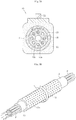
- the second tubular member 15 is made of a graphite material or a silicon carbide material, and eight circular small holes 15b are formed at equal intervals in a circumferential direction around a central large circular hole 15a.
- the mixing ratio in the case where the second tubular member 14 is made of a mixed material of the silicon carbide material and the graphite material is, for example, 5% to 70% with the silicon carbide material, and 30% to 95 % with the graphite material.
- the silicon carbide material is 15% and the graphite material is 85%.
- the proportion of the silicon carbide material is in the range of at most 10% to 30%, desirably 12% to 24%, and more desirably 15% to 18% as with the first embodiment.
- the rest of the mixed material is all the graphite material.
- the second tubular member 15 is configured to allow the fiber member F containing carbon, for example, one carbon fiber thread F to run and pass through the small holes 15b at a predetermined speed with a predetermined tension applied. By doing so, the production efficiency of the calcined fiber member F can be improved more than in the first embodiment.
- Both end portions in the longitudinal direction of the second tubular member 15 are supported by supporting members arranged on the outer sides of both end portions of the first tubular member 13 as with the first embodiment.
- a plurality (seven) of the second tubular members 15 of the second embodiment are disposed inside the first tubular member 13. That is, six second tubular members 15 are arranged around the second tubular member 15 at the center without clearance. By doing so, the production efficiency of the calcined fiber member F is dramatically improved.
- the microwave heating apparatus 10 is configured as described above, and the operation of the microwave heating apparatus 10 is as follows.
- microwaves are irradiated from the upper and lower microwave irradiators 12, the microwaves permeate through the furnace main body of the heating furnace 11 and heat the first tubular member 13. Thereby, a temperature of the first tubular member 13 is elevated, and the inner second tubular member 14 (15) is heated by radiant heat from the first tubular member 13.
- the microwaves from the microwave irradiators 12 not only heat the first tubular member 13 but also reach the second tubular member 14 (15) through the holes or slits of the first tubular member 13.
- the microwave further permeate through the graphite of the second tubular member 14 (15) and directly irradiate the fiber member F on the inner side of the second tubular member 14 (15).
- the calcining temperature of the fiber member F reaches at least 1,000°C to 2,500°C, inclusive, and when the fiber member F is a carbon fiber, graphitization of the fiber or formation of graphitized fiber is promoted in a high temperature region exceeding 2,500°C.
- Fig. 5 is a temperature distribution curve obtained by measuring the temperature distribution in the furnace in an axial direction.
- the solid line shows the temperature distribution curve measured when the first tubular member 13 is rotated at 5 rpm and the broken line shows the temperature distribution curve measured when the first tubular member 13 is fixed.
- the best temperature uniformity was achieved when the rotation number of the first tubular member 13 was 5 rpm, even with a rotational speed other than 5 rpm, as compared with the case of fixing the first tubular member 13, obvious superiority of thermal uniformity was recognized. Accordingly, unevenness in temperature distribution can be eliminated by rotating the first tubular member 13 at an arbitrary rotational speed of, for example, 1 to 50 rpm.
- Tables 1 and 2 are shown test results of tests of tensile strength (Table 1) and elastic strength (Table 2) of calcined carbon fibers (Table 1) and graphitized fibers (Table 2) which were obtained by heating and calcining carbon fibers using the heating furnace 11 of the embodiment of the present invention.
- Carbon Fiber before Calcination (Single Fiber of 0.67 dTex) Calcined and Graphitized Fiber First Tubular Member 13 not Rotated Only Radiant heating (2,500°C) First Tubular Member 13 Rotated Microwave Direct Irradiation + Radiant heating (2,500°C) Z1 223 402 466 Z2 375 452 Z3 428 498 Z4 404 459 Z5 411 468
- the present invention is not limited to the above-described embodiments and various variations may be made.
- two microwave irradiators 12 are arranged at the top and bottom, but the number and position of the microwave irradiators 12 can be appropriately increased and decreased or moved.
- the shapes of the first tubular member 13 and the second tubular members 14, 15 are both cylindrical, these tubular members are not necessarily cylindrical.
- the second tubular member 14 or 15 since the second tubular member 14 or 15 does not rotate, it is also possible for the second tubular member 14 or 15 to have an arbitrary cross-sectional shape, for example, a rectangular cross section or the like.
Landscapes
- Physics & Mathematics (AREA)
- Electromagnetism (AREA)
- Engineering & Computer Science (AREA)
- Manufacturing & Machinery (AREA)
- Chemical & Material Sciences (AREA)
- Chemical Kinetics & Catalysis (AREA)
- General Chemical & Material Sciences (AREA)
- Textile Engineering (AREA)
- Inorganic Fibers (AREA)
- Furnace Details (AREA)
- Constitution Of High-Frequency Heating (AREA)
Applications Claiming Priority (2)
| Application Number | Priority Date | Filing Date | Title |
|---|---|---|---|
| JP2016251421A JP6151844B1 (ja) | 2016-12-26 | 2016-12-26 | マイクロ波加熱装置 |
| PCT/JP2017/025551 WO2018123117A1 (fr) | 2016-12-26 | 2017-07-13 | Dispositif chauffant à micro-ondes |
Publications (3)
| Publication Number | Publication Date |
|---|---|
| EP3367751A1 true EP3367751A1 (fr) | 2018-08-29 |
| EP3367751A4 EP3367751A4 (fr) | 2018-10-24 |
| EP3367751B1 EP3367751B1 (fr) | 2019-10-02 |
Family
ID=59082027
Family Applications (1)
| Application Number | Title | Priority Date | Filing Date |
|---|---|---|---|
| EP17794890.8A Active EP3367751B1 (fr) | 2016-12-26 | 2017-07-13 | Dispositif chauffant à micro-ondes |
Country Status (6)
| Country | Link |
|---|---|
| US (1) | US10349471B2 (fr) |
| EP (1) | EP3367751B1 (fr) |
| JP (1) | JP6151844B1 (fr) |
| KR (1) | KR101871205B1 (fr) |
| CN (1) | CN107820522B (fr) |
| WO (1) | WO2018123117A1 (fr) |
Families Citing this family (15)
| Publication number | Priority date | Publication date | Assignee | Title |
|---|---|---|---|---|
| JP7278569B2 (ja) * | 2018-12-18 | 2023-05-22 | マイクロ波化学株式会社 | マイクロ波処理装置、および炭素繊維の製造方法 |
| KR102405323B1 (ko) * | 2018-07-23 | 2022-06-07 | 주식회사 엘지화학 | 마이크로웨이브를 이용한 탄소 섬유 탄화 장치 |
| KR102282277B1 (ko) * | 2018-09-03 | 2021-07-28 | 주식회사 엘지화학 | 마이크로파 소성로 및 이를 이용한 양극 활물질의 소성 방법 |
| JP7042490B2 (ja) * | 2018-11-26 | 2022-03-28 | マイクロ波化学株式会社 | マイクロ波処理装置、および炭素繊維の製造方法 |
| CN109594151A (zh) * | 2018-12-25 | 2019-04-09 | 中国科学院合肥物质科学研究院 | 一种优化碳纤维石墨化的设备 |
| CN110719658A (zh) * | 2019-10-29 | 2020-01-21 | 上海埃梅奇高分子材料科技发展有限公司 | 一种波能分子振荡集热器 |
| CN110691439A (zh) * | 2019-10-29 | 2020-01-14 | 上海埃梅奇高分子材料科技发展有限公司 | 一种基于波能分子振荡集热器的热系统 |
| CN110719659A (zh) * | 2019-10-29 | 2020-01-21 | 上海埃梅奇高分子材料科技发展有限公司 | 一种用于波能分子振荡集热器的电介质 |
| JP6881793B1 (ja) * | 2020-02-07 | 2021-06-02 | マイクロ波化学株式会社 | マイクロ波処理装置、及びマイクロ波処理方法 |
| JP6842786B1 (ja) * | 2020-02-10 | 2021-03-17 | マイクロ波化学株式会社 | マイクロ波処理装置、及びマイクロ波処理方法 |
| CN116026105B (zh) * | 2021-10-27 | 2025-01-21 | 张存续 | 利用准行微波实现热处理的材料处理设备 |
| CN114083692B (zh) * | 2021-12-07 | 2023-02-28 | 孙勇 | 一种湿拌抹灰砂浆的工艺方法 |
| JP2024017910A (ja) * | 2022-07-28 | 2024-02-08 | 京セラ株式会社 | マイクロ波加熱装置用筒状部材 |
| CN115978785B (zh) * | 2022-12-19 | 2024-03-19 | 四川大学 | 一种同轴开缝辐射器、连续流液体加热系统及加热方法 |
| JP7834261B2 (ja) * | 2023-09-28 | 2026-03-24 | 江蘇亨睿航空工業有限公司 | 中高弾性率ラージトウ炭素繊維の製造方法 |
Family Cites Families (20)
| Publication number | Priority date | Publication date | Assignee | Title |
|---|---|---|---|---|
| JPS4724186Y1 (fr) | 1969-04-28 | 1972-08-01 | ||
| JPS5877448A (ja) | 1981-11-04 | 1983-05-10 | Honda Motor Co Ltd | 研削加工装置のワ−ク保持装置 |
| JPS6351641A (ja) | 1986-08-21 | 1988-03-04 | Oki Electric Ind Co Ltd | 単結晶または多結晶Si膜の微細パタ−ン形成方法 |
| JPH0420502Y2 (fr) * | 1986-09-18 | 1992-05-11 | ||
| JP2588012B2 (ja) * | 1988-12-20 | 1997-03-05 | 呉羽化学工業株式会社 | 黒鉛化質短繊維の製造方法及び製造装置 |
| JP2001296010A (ja) * | 2000-04-13 | 2001-10-26 | Meidensha Corp | 回転加熱処理炉の加熱処理方法 |
| JP2002013031A (ja) * | 2000-06-28 | 2002-01-18 | Nippon Steel Corp | 炭素材料の黒鉛化方法及びその装置 |
| US20050103778A1 (en) * | 2001-07-20 | 2005-05-19 | Aykanian Arthur A. | Microwave desorder |
| US7687045B2 (en) * | 2001-11-26 | 2010-03-30 | Biodefense Corporation | Article processing apparatus and related method |
| CN1202298C (zh) * | 2002-03-05 | 2005-05-18 | 陈新谋 | 一腔多管高频加热装置 |
| WO2006101084A1 (fr) * | 2005-03-23 | 2006-09-28 | Bridgestone Corporation | Fibre de carbone, procedes pour la produire (en continu) et utilisation dans des structures catalytiques, electrodes pour piles a combustible a polymere solide et piles a combustible a polymere solide |
| US7824495B1 (en) * | 2005-11-09 | 2010-11-02 | Ut-Battelle, Llc | System to continuously produce carbon fiber via microwave assisted plasma processing |
| DE502006007528D1 (de) | 2006-04-15 | 2010-09-09 | Toho Tenax Co Ltd | Verfahren zur kontinuierlichen Herstellung von Kohlenstofffasern |
| US20110139773A1 (en) * | 2009-12-16 | 2011-06-16 | Magnus Fagrell | Non-Modal Interplate Microwave Heating System and Method of Heating |
| JP5787289B2 (ja) * | 2011-06-20 | 2015-09-30 | ミクロ電子株式会社 | マイクロ波を応用した加熱装置 |
| KR20130110237A (ko) * | 2012-03-17 | 2013-10-10 | 임채구 | 마이크로파를 이용한 가열방법 및 가열장치 |
| JP2013231244A (ja) * | 2012-04-27 | 2013-11-14 | Applied Materials Inc | 炭素繊維の製造装置 |
| CN202830266U (zh) * | 2012-07-12 | 2013-03-27 | 永虹科技股份有限公司 | 高模数石墨纤维的制造装置 |
| JP5877448B2 (ja) | 2012-09-26 | 2016-03-08 | ミクロ電子株式会社 | マイクロ波を応用した加熱装置 |
| CN202918530U (zh) * | 2012-11-15 | 2013-05-01 | 上海明光电子科技有限公司 | 微波加热装置 |
-
2016
- 2016-12-26 JP JP2016251421A patent/JP6151844B1/ja active Active
-
2017
- 2017-07-13 EP EP17794890.8A patent/EP3367751B1/fr active Active
- 2017-07-13 WO PCT/JP2017/025551 patent/WO2018123117A1/fr not_active Ceased
- 2017-07-13 US US15/572,079 patent/US10349471B2/en not_active Expired - Fee Related
- 2017-07-13 KR KR1020177032873A patent/KR101871205B1/ko not_active Expired - Fee Related
- 2017-07-13 CN CN201780001654.8A patent/CN107820522B/zh not_active Expired - Fee Related
Also Published As
| Publication number | Publication date |
|---|---|
| CN107820522A (zh) | 2018-03-20 |
| JP2018106893A (ja) | 2018-07-05 |
| EP3367751A4 (fr) | 2018-10-24 |
| JP6151844B1 (ja) | 2017-06-21 |
| US20180352616A1 (en) | 2018-12-06 |
| KR101871205B1 (ko) | 2018-06-27 |
| CN107820522B (zh) | 2019-04-09 |
| EP3367751B1 (fr) | 2019-10-02 |
| US10349471B2 (en) | 2019-07-09 |
| WO2018123117A1 (fr) | 2018-07-05 |
Similar Documents
| Publication | Publication Date | Title |
|---|---|---|
| US10349471B2 (en) | Microwave heating apparatus | |
| Kim et al. | Continuous and rapid stabilization of polyacrylonitrile fiber bundles assisted by atmospheric pressure plasma for fabricating large-tow carbon fibers | |
| CN105734671B (zh) | 一种高质量碳化硅晶体生长的方法 | |
| Harrell et al. | Influence of oxygen uptake on pitch carbon fiber | |
| KR20060020675A (ko) | 구조재용 지지체 및 그의 제조 방법 | |
| CN103541042B (zh) | 高模数石墨纤维及其制造方法 | |
| KR102037843B1 (ko) | 마이크로웨이브파를 이용한 탄소 섬유 제조 장치 | |
| TWI475131B (zh) | 鉭元件之滲碳處理方法及鉭元件 | |
| CN102534866B (zh) | 高模量碳纤维及其制造方法 | |
| Liu et al. | Morphology adjustment of SnO 2 and SnO 2/CeO 2 one dimensional nanostructures towards applications in gas sensing and CO oxidation | |
| Wang et al. | Preparation process of mesophase pitch-based carbon fiber: a review | |
| CN107119348B (zh) | 一种石墨纤维及其制备方法 | |
| RU2694340C1 (ru) | Способ получения текстильных карбидокремниевых материалов | |
| Wang et al. | Effect of cyclization degree of nitrogen thermal pretreatment on radial structure of PAN stabilized fibers | |
| JP6677553B2 (ja) | 炭素材料の製造方法 | |
| KR101711810B1 (ko) | 탄소섬유 제조장치 | |
| KR102508851B1 (ko) | 반절연 탄화규소 단결정의 제조 방법 및 이로부터 제조된 반절연 탄화규소 단결정 | |
| Liu et al. | A Comparison Study of the Synergistic Influence of Discrepancy in Exothermic Behavior of Polyacrylonitrile‐Based Precursor Fibers and the Continuous Gradient Pre‐Oxidation Condition on Stabilization Structure | |
| KR20180110643A (ko) | 탄소섬유 제조용 전구체 섬유, 이의 제조방법 및 이를 이용한 탄소섬유의 제조방법 | |
| JP2011032125A (ja) | シリコン単結晶製造装置用ルツボ保護シート、シリコン単結晶製造装置、およびシリコン単結晶製造方法 | |
| Pan et al. | A New Process for the Carbonization of Centrifugal Electrospun Polyacrylonitrile Nanofibers Driven by Rapid Joule Heating | |
| KR102687569B1 (ko) | 탄소섬유 전구체의 제조방법 | |
| KR101893490B1 (ko) | 실리콘 카바이드 제조장치 | |
| JP2588012B2 (ja) | 黒鉛化質短繊維の製造方法及び製造装置 | |
| RU2622061C1 (ru) | Способ пропитки изделий из пористого углерод-углеродного композиционного материала |
Legal Events
| Date | Code | Title | Description |
|---|---|---|---|
| STAA | Information on the status of an ep patent application or granted ep patent |
Free format text: STATUS: UNKNOWN |
|
| STAA | Information on the status of an ep patent application or granted ep patent |
Free format text: STATUS: THE INTERNATIONAL PUBLICATION HAS BEEN MADE |
|
| PUAI | Public reference made under article 153(3) epc to a published international application that has entered the european phase |
Free format text: ORIGINAL CODE: 0009012 |
|
| STAA | Information on the status of an ep patent application or granted ep patent |
Free format text: STATUS: REQUEST FOR EXAMINATION WAS MADE |
|
| 17P | Request for examination filed |
Effective date: 20171117 |
|
| AK | Designated contracting states |
Kind code of ref document: A1 Designated state(s): AL AT BE BG CH CY CZ DE DK EE ES FI FR GB GR HR HU IE IS IT LI LT LU LV MC MK MT NL NO PL PT RO RS SE SI SK SM TR |
|
| AX | Request for extension of the european patent |
Extension state: BA ME |
|
| RIC1 | Information provided on ipc code assigned before grant |
Ipc: D01F 9/32 20060101ALI20180913BHEP Ipc: H05B 6/64 20060101ALI20180913BHEP Ipc: H05B 6/78 20060101ALI20180913BHEP Ipc: H05B 6/70 20060101ALI20180913BHEP Ipc: H05B 6/80 20060101AFI20180913BHEP |
|
| A4 | Supplementary search report drawn up and despatched |
Effective date: 20180921 |
|
| GRAP | Despatch of communication of intention to grant a patent |
Free format text: ORIGINAL CODE: EPIDOSNIGR1 |
|
| STAA | Information on the status of an ep patent application or granted ep patent |
Free format text: STATUS: GRANT OF PATENT IS INTENDED |
|
| RIC1 | Information provided on ipc code assigned before grant |
Ipc: D01F 9/32 20060101ALI20190429BHEP Ipc: H05B 6/80 20060101AFI20190429BHEP Ipc: H05B 6/64 20060101ALI20190429BHEP Ipc: H05B 6/70 20060101ALI20190429BHEP Ipc: H05B 6/78 20060101ALI20190429BHEP |
|
| DAV | Request for validation of the european patent (deleted) | ||
| DAX | Request for extension of the european patent (deleted) | ||
| INTG | Intention to grant announced |
Effective date: 20190522 |
|
| GRAS | Grant fee paid |
Free format text: ORIGINAL CODE: EPIDOSNIGR3 |
|
| GRAA | (expected) grant |
Free format text: ORIGINAL CODE: 0009210 |
|
| STAA | Information on the status of an ep patent application or granted ep patent |
Free format text: STATUS: THE PATENT HAS BEEN GRANTED |
|
| AK | Designated contracting states |
Kind code of ref document: B1 Designated state(s): AL AT BE BG CH CY CZ DE DK EE ES FI FR GB GR HR HU IE IS IT LI LT LU LV MC MK MT NL NO PL PT RO RS SE SI SK SM TR |
|
| REG | Reference to a national code |
Ref country code: GB Ref legal event code: FG4D |
|
| REG | Reference to a national code |
Ref country code: CH Ref legal event code: EP Ref country code: AT Ref legal event code: REF Ref document number: 1187676 Country of ref document: AT Kind code of ref document: T Effective date: 20191015 |
|
| REG | Reference to a national code |
Ref country code: DE Ref legal event code: R096 Ref document number: 602017007511 Country of ref document: DE |
|
| REG | Reference to a national code |
Ref country code: IE Ref legal event code: FG4D |
|
| REG | Reference to a national code |
Ref country code: DE Ref legal event code: R082 Ref document number: 602017007511 Country of ref document: DE Representative=s name: EDER SCHIESCHKE & PARTNER MBB, PATENTANWAELTE, DE |
|
| REG | Reference to a national code |
Ref country code: NL Ref legal event code: MP Effective date: 20191002 |
|
| REG | Reference to a national code |
Ref country code: LT Ref legal event code: MG4D |
|
| REG | Reference to a national code |
Ref country code: AT Ref legal event code: MK05 Ref document number: 1187676 Country of ref document: AT Kind code of ref document: T Effective date: 20191002 |
|
| PG25 | Lapsed in a contracting state [announced via postgrant information from national office to epo] |
Ref country code: FI Free format text: LAPSE BECAUSE OF FAILURE TO SUBMIT A TRANSLATION OF THE DESCRIPTION OR TO PAY THE FEE WITHIN THE PRESCRIBED TIME-LIMIT Effective date: 20191002 Ref country code: PT Free format text: LAPSE BECAUSE OF FAILURE TO SUBMIT A TRANSLATION OF THE DESCRIPTION OR TO PAY THE FEE WITHIN THE PRESCRIBED TIME-LIMIT Effective date: 20200203 Ref country code: BG Free format text: LAPSE BECAUSE OF FAILURE TO SUBMIT A TRANSLATION OF THE DESCRIPTION OR TO PAY THE FEE WITHIN THE PRESCRIBED TIME-LIMIT Effective date: 20200102 Ref country code: LT Free format text: LAPSE BECAUSE OF FAILURE TO SUBMIT A TRANSLATION OF THE DESCRIPTION OR TO PAY THE FEE WITHIN THE PRESCRIBED TIME-LIMIT Effective date: 20191002 Ref country code: NL Free format text: LAPSE BECAUSE OF FAILURE TO SUBMIT A TRANSLATION OF THE DESCRIPTION OR TO PAY THE FEE WITHIN THE PRESCRIBED TIME-LIMIT Effective date: 20191002 Ref country code: AT Free format text: LAPSE BECAUSE OF FAILURE TO SUBMIT A TRANSLATION OF THE DESCRIPTION OR TO PAY THE FEE WITHIN THE PRESCRIBED TIME-LIMIT Effective date: 20191002 Ref country code: ES Free format text: LAPSE BECAUSE OF FAILURE TO SUBMIT A TRANSLATION OF THE DESCRIPTION OR TO PAY THE FEE WITHIN THE PRESCRIBED TIME-LIMIT Effective date: 20191002 Ref country code: PL Free format text: LAPSE BECAUSE OF FAILURE TO SUBMIT A TRANSLATION OF THE DESCRIPTION OR TO PAY THE FEE WITHIN THE PRESCRIBED TIME-LIMIT Effective date: 20191002 Ref country code: GR Free format text: LAPSE BECAUSE OF FAILURE TO SUBMIT A TRANSLATION OF THE DESCRIPTION OR TO PAY THE FEE WITHIN THE PRESCRIBED TIME-LIMIT Effective date: 20200103 Ref country code: NO Free format text: LAPSE BECAUSE OF FAILURE TO SUBMIT A TRANSLATION OF THE DESCRIPTION OR TO PAY THE FEE WITHIN THE PRESCRIBED TIME-LIMIT Effective date: 20200102 Ref country code: SE Free format text: LAPSE BECAUSE OF FAILURE TO SUBMIT A TRANSLATION OF THE DESCRIPTION OR TO PAY THE FEE WITHIN THE PRESCRIBED TIME-LIMIT Effective date: 20191002 Ref country code: LV Free format text: LAPSE BECAUSE OF FAILURE TO SUBMIT A TRANSLATION OF THE DESCRIPTION OR TO PAY THE FEE WITHIN THE PRESCRIBED TIME-LIMIT Effective date: 20191002 |
|
| PG25 | Lapsed in a contracting state [announced via postgrant information from national office to epo] |
Ref country code: CZ Free format text: LAPSE BECAUSE OF FAILURE TO SUBMIT A TRANSLATION OF THE DESCRIPTION OR TO PAY THE FEE WITHIN THE PRESCRIBED TIME-LIMIT Effective date: 20191002 Ref country code: RS Free format text: LAPSE BECAUSE OF FAILURE TO SUBMIT A TRANSLATION OF THE DESCRIPTION OR TO PAY THE FEE WITHIN THE PRESCRIBED TIME-LIMIT Effective date: 20191002 Ref country code: HR Free format text: LAPSE BECAUSE OF FAILURE TO SUBMIT A TRANSLATION OF THE DESCRIPTION OR TO PAY THE FEE WITHIN THE PRESCRIBED TIME-LIMIT Effective date: 20191002 Ref country code: IS Free format text: LAPSE BECAUSE OF FAILURE TO SUBMIT A TRANSLATION OF THE DESCRIPTION OR TO PAY THE FEE WITHIN THE PRESCRIBED TIME-LIMIT Effective date: 20200224 |
|
| PG25 | Lapsed in a contracting state [announced via postgrant information from national office to epo] |
Ref country code: AL Free format text: LAPSE BECAUSE OF FAILURE TO SUBMIT A TRANSLATION OF THE DESCRIPTION OR TO PAY THE FEE WITHIN THE PRESCRIBED TIME-LIMIT Effective date: 20191002 |
|
| REG | Reference to a national code |
Ref country code: DE Ref legal event code: R097 Ref document number: 602017007511 Country of ref document: DE |
|
| PG2D | Information on lapse in contracting state deleted |
Ref country code: IS |
|
| PG25 | Lapsed in a contracting state [announced via postgrant information from national office to epo] |
Ref country code: RO Free format text: LAPSE BECAUSE OF FAILURE TO SUBMIT A TRANSLATION OF THE DESCRIPTION OR TO PAY THE FEE WITHIN THE PRESCRIBED TIME-LIMIT Effective date: 20191002 Ref country code: EE Free format text: LAPSE BECAUSE OF FAILURE TO SUBMIT A TRANSLATION OF THE DESCRIPTION OR TO PAY THE FEE WITHIN THE PRESCRIBED TIME-LIMIT Effective date: 20191002 Ref country code: DK Free format text: LAPSE BECAUSE OF FAILURE TO SUBMIT A TRANSLATION OF THE DESCRIPTION OR TO PAY THE FEE WITHIN THE PRESCRIBED TIME-LIMIT Effective date: 20191002 Ref country code: IS Free format text: LAPSE BECAUSE OF FAILURE TO SUBMIT A TRANSLATION OF THE DESCRIPTION OR TO PAY THE FEE WITHIN THE PRESCRIBED TIME-LIMIT Effective date: 20200202 |
|
| PLBE | No opposition filed within time limit |
Free format text: ORIGINAL CODE: 0009261 |
|
| STAA | Information on the status of an ep patent application or granted ep patent |
Free format text: STATUS: NO OPPOSITION FILED WITHIN TIME LIMIT |
|
| PG25 | Lapsed in a contracting state [announced via postgrant information from national office to epo] |
Ref country code: SK Free format text: LAPSE BECAUSE OF FAILURE TO SUBMIT A TRANSLATION OF THE DESCRIPTION OR TO PAY THE FEE WITHIN THE PRESCRIBED TIME-LIMIT Effective date: 20191002 Ref country code: SM Free format text: LAPSE BECAUSE OF FAILURE TO SUBMIT A TRANSLATION OF THE DESCRIPTION OR TO PAY THE FEE WITHIN THE PRESCRIBED TIME-LIMIT Effective date: 20191002 Ref country code: IT Free format text: LAPSE BECAUSE OF FAILURE TO SUBMIT A TRANSLATION OF THE DESCRIPTION OR TO PAY THE FEE WITHIN THE PRESCRIBED TIME-LIMIT Effective date: 20191002 |
|
| 26N | No opposition filed |
Effective date: 20200703 |
|
| PG25 | Lapsed in a contracting state [announced via postgrant information from national office to epo] |
Ref country code: SI Free format text: LAPSE BECAUSE OF FAILURE TO SUBMIT A TRANSLATION OF THE DESCRIPTION OR TO PAY THE FEE WITHIN THE PRESCRIBED TIME-LIMIT Effective date: 20191002 |
|
| PG25 | Lapsed in a contracting state [announced via postgrant information from national office to epo] |
Ref country code: MC Free format text: LAPSE BECAUSE OF FAILURE TO SUBMIT A TRANSLATION OF THE DESCRIPTION OR TO PAY THE FEE WITHIN THE PRESCRIBED TIME-LIMIT Effective date: 20191002 |
|
| REG | Reference to a national code |
Ref country code: CH Ref legal event code: PL |
|
| REG | Reference to a national code |
Ref country code: BE Ref legal event code: MM Effective date: 20200731 |
|
| PG25 | Lapsed in a contracting state [announced via postgrant information from national office to epo] |
Ref country code: CH Free format text: LAPSE BECAUSE OF NON-PAYMENT OF DUE FEES Effective date: 20200731 Ref country code: LU Free format text: LAPSE BECAUSE OF NON-PAYMENT OF DUE FEES Effective date: 20200713 Ref country code: LI Free format text: LAPSE BECAUSE OF NON-PAYMENT OF DUE FEES Effective date: 20200731 |
|
| PG25 | Lapsed in a contracting state [announced via postgrant information from national office to epo] |
Ref country code: BE Free format text: LAPSE BECAUSE OF NON-PAYMENT OF DUE FEES Effective date: 20200731 |
|
| PG25 | Lapsed in a contracting state [announced via postgrant information from national office to epo] |
Ref country code: IE Free format text: LAPSE BECAUSE OF NON-PAYMENT OF DUE FEES Effective date: 20200713 |
|
| PGFP | Annual fee paid to national office [announced via postgrant information from national office to epo] |
Ref country code: FR Payment date: 20210722 Year of fee payment: 5 |
|
| PGFP | Annual fee paid to national office [announced via postgrant information from national office to epo] |
Ref country code: DE Payment date: 20210720 Year of fee payment: 5 |
|
| GBPC | Gb: european patent ceased through non-payment of renewal fee |
Effective date: 20210713 |
|
| PG25 | Lapsed in a contracting state [announced via postgrant information from national office to epo] |
Ref country code: GB Free format text: LAPSE BECAUSE OF NON-PAYMENT OF DUE FEES Effective date: 20210713 |
|
| PG25 | Lapsed in a contracting state [announced via postgrant information from national office to epo] |
Ref country code: TR Free format text: LAPSE BECAUSE OF FAILURE TO SUBMIT A TRANSLATION OF THE DESCRIPTION OR TO PAY THE FEE WITHIN THE PRESCRIBED TIME-LIMIT Effective date: 20191002 Ref country code: MT Free format text: LAPSE BECAUSE OF FAILURE TO SUBMIT A TRANSLATION OF THE DESCRIPTION OR TO PAY THE FEE WITHIN THE PRESCRIBED TIME-LIMIT Effective date: 20191002 Ref country code: CY Free format text: LAPSE BECAUSE OF FAILURE TO SUBMIT A TRANSLATION OF THE DESCRIPTION OR TO PAY THE FEE WITHIN THE PRESCRIBED TIME-LIMIT Effective date: 20191002 |
|
| PG25 | Lapsed in a contracting state [announced via postgrant information from national office to epo] |
Ref country code: MK Free format text: LAPSE BECAUSE OF FAILURE TO SUBMIT A TRANSLATION OF THE DESCRIPTION OR TO PAY THE FEE WITHIN THE PRESCRIBED TIME-LIMIT Effective date: 20191002 |
|
| REG | Reference to a national code |
Ref country code: DE Ref legal event code: R119 Ref document number: 602017007511 Country of ref document: DE |
|
| PG25 | Lapsed in a contracting state [announced via postgrant information from national office to epo] |
Ref country code: FR Free format text: LAPSE BECAUSE OF NON-PAYMENT OF DUE FEES Effective date: 20220731 |
|
| PG25 | Lapsed in a contracting state [announced via postgrant information from national office to epo] |
Ref country code: DE Free format text: LAPSE BECAUSE OF NON-PAYMENT OF DUE FEES Effective date: 20230201 |