EP3367854B1 - Dynamische wasserdispersion und braukammerreiniger - Google Patents
Dynamische wasserdispersion und braukammerreiniger Download PDFInfo
- Publication number
- EP3367854B1 EP3367854B1 EP16861024.4A EP16861024A EP3367854B1 EP 3367854 B1 EP3367854 B1 EP 3367854B1 EP 16861024 A EP16861024 A EP 16861024A EP 3367854 B1 EP3367854 B1 EP 3367854B1
- Authority
- EP
- European Patent Office
- Prior art keywords
- brewing chamber
- cleaner
- brewing
- lid
- extraction needle
- Prior art date
- Legal status (The legal status is an assumption and is not a legal conclusion. Google has not performed a legal analysis and makes no representation as to the accuracy of the status listed.)
- Active
Links
- XLYOFNOQVPJJNP-UHFFFAOYSA-N water Substances O XLYOFNOQVPJJNP-UHFFFAOYSA-N 0.000 title claims description 103
- 239000006185 dispersion Substances 0.000 title description 38
- 239000000463 material Substances 0.000 claims description 88
- 235000016213 coffee Nutrition 0.000 claims description 74
- 235000013353 coffee beverage Nutrition 0.000 claims description 74
- 238000000605 extraction Methods 0.000 claims description 54
- 239000007921 spray Substances 0.000 claims description 40
- 238000004140 cleaning Methods 0.000 claims description 19
- 239000007788 liquid Substances 0.000 claims description 12
- 238000004891 communication Methods 0.000 claims description 11
- 239000012530 fluid Substances 0.000 claims description 11
- 235000013361 beverage Nutrition 0.000 claims description 9
- 241000555745 Sciuridae Species 0.000 claims description 6
- 230000000717 retained effect Effects 0.000 claims 1
- 238000009987 spinning Methods 0.000 description 17
- 238000004804 winding Methods 0.000 description 8
- 238000010438 heat treatment Methods 0.000 description 4
- 238000002347 injection Methods 0.000 description 4
- 239000007924 injection Substances 0.000 description 4
- 238000000034 method Methods 0.000 description 4
- 239000011248 coating agent Substances 0.000 description 2
- 238000000576 coating method Methods 0.000 description 2
- 238000010586 diagram Methods 0.000 description 2
- 235000015114 espresso Nutrition 0.000 description 2
- 230000001939 inductive effect Effects 0.000 description 2
- 238000003825 pressing Methods 0.000 description 2
- 239000000243 solution Substances 0.000 description 2
- 241000533293 Sesbania emerus Species 0.000 description 1
- 230000003203 everyday effect Effects 0.000 description 1
- 239000000284 extract Substances 0.000 description 1
- 239000000796 flavoring agent Substances 0.000 description 1
- 235000019634 flavors Nutrition 0.000 description 1
- 239000008236 heating water Substances 0.000 description 1
- 238000005259 measurement Methods 0.000 description 1
- 238000012986 modification Methods 0.000 description 1
- 230000004048 modification Effects 0.000 description 1
- 230000008447 perception Effects 0.000 description 1
- 238000007789 sealing Methods 0.000 description 1
- 238000005507 spraying Methods 0.000 description 1
- 238000005406 washing Methods 0.000 description 1
Images



Classifications
-
- A—HUMAN NECESSITIES
- A47—FURNITURE; DOMESTIC ARTICLES OR APPLIANCES; COFFEE MILLS; SPICE MILLS; SUCTION CLEANERS IN GENERAL
- A47J—KITCHEN EQUIPMENT; COFFEE MILLS; SPICE MILLS; APPARATUS FOR MAKING BEVERAGES
- A47J31/00—Apparatus for making beverages
- A47J31/44—Parts or details or accessories of beverage-making apparatus
- A47J31/4403—Constructional details
- A47J31/4475—Hot water outlets for drip coffee makers
-
- A—HUMAN NECESSITIES
- A47—FURNITURE; DOMESTIC ARTICLES OR APPLIANCES; COFFEE MILLS; SPICE MILLS; SUCTION CLEANERS IN GENERAL
- A47J—KITCHEN EQUIPMENT; COFFEE MILLS; SPICE MILLS; APPARATUS FOR MAKING BEVERAGES
- A47J31/00—Apparatus for making beverages
- A47J31/44—Parts or details or accessories of beverage-making apparatus
- A47J31/60—Cleaning devices
Definitions
- the present invention relates to beverage brewing and in particular to a liquid spray into a brewing chamber for cleaning the brewing chamber.
- Brewed beverages are often prepared by injecting water into a brewing chamber containing a brewing material such as ground coffee beans.
- a brewing material such as ground coffee beans.
- Various configurations are known including inserting a needle into the brewing material, streams of water injected down into the brewing material.
- water released or sprayed into the brewing material may form channels or pockets, and the brewed beverage is not uniformly extracted from the brewing material.
- the brewing chamber may accumulate residue from various brewing material and extracts. Such residue may alter the desired flavor of future brewed drinks. Apparatus and methods are needed to improve cleaning the brewing chamber.
- the present invention addresses the above and other needs by providing a brewing chamber cleaner according to claim 1.
- the assembly may be attached to a disk configured to removably reside in the brewing chamber for brewing or cleaning, or be part of a coffee maker. Liquid pumped into the assembly may cause the assembly to spin by the liquid flowing past gears or a propeller, or by tangential sprays on a spinning member.
- the coffee maker includes a rotating shaft to cause the spinning member to spin or may include stator winding creating a rotating magnetic field to cause the spinning member to spin.
- the assembly includes a wide spray provided by a fixed nozzle. A base is optionally provided to capture the spray for cleaning and direct a flow into a bottom extraction needle of the coffee maker to clean the extraction needle.
- a brewing chamber cleaner including a spinning or stationary assembly for uniformly spraying water into the brewing chamber.
- the spinning assembly may be attached to a disk configured to removably reside in the brewing chamber, or be part of a coffee maker.
- the water is sprayed in a moving pattern to clean the brewing chamber.
- water is pumped into the removable cleaner, and the flow of water causes the spinning assembly to spin by the water flowing past gears or a propeller, or by tangential jets on the spinning member.
- the coffee maker includes a rotating shaft engaging the cleaner to cause the spinning assembly to spin, or may include stator winding creating a rotating magnetic field in the brewing chamber to cause the spinning assembly to spin.
- a wide spray is provided by a fixed nozzle.
- a base is optionally provided to capture the spray and direct a flow into a bottom extraction needle of the coffee maker.
- a spinning assembly for uniformly dispersing water into brewing material.
- the spinning assembly may be attached to a removable holder lid, reside in the base of the holder, or be part of the coffee maker.
- the flow of water is sprayed into brewing material contained in the brewing chamber.
- water is pumped into the brewing material holder, and the flow of water causes the spinning assembly to spin by the water flowing past gears or a propeller, or by tangential jets on the spinning member.
- the coffee maker includes a rotating shaft engaging the brewing material holder to cause the spinning assembly to spin.
- the coffee maker includes stator winding creating a rotating magnetic field in the brewing chamber to cause the spinning assembly to spin.
- a large variety of coffee and espresso makers are commonly used to make beverages.
- the coffee and espresso makers are often used one or more times every day, and residue builds as a result of the use.
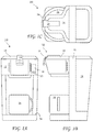
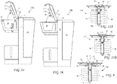
- FIG. 1A A front view of a coffee maker 10 according to the present invention is shown in FIG. 1A a side view of the coffee maker 10 is shown in FIG. 1B , and a top view of the coffee maker 10 is shown in FIG. 1C .
- the coffee maker 10 includes a base 12, a brewing chamber lid 14, a lid handle 16, a water container 18, a display 20, controls 22, and platform 24.
- a cup 26 rests on the platform 24.
- the coffee maker 10 provides a flow of hot water through brewing material to produce a brewed drink.
- the flow of water may be heated by one of any known means, for example, an electrical heating coil, inductive heating, or a conductive coating on tubing carrying the water.
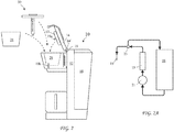
- FIG. 2 A side view of the coffee maker 10 with a brewing chamber lid 14 allowing placement of a brewing material holder 28, and/or a brewing chamber accessory 31, according to the present invention inside a brewing chamber 29 of the coffee maker 10 is shown in FIG. 2 .
- the brewing chamber lid 14 includes a lid hinge 14' and a water tube 15 carries heated water into the lid 14.
- a pad 17 resides on a bottom surface of the brewing chamber lid 14 and presses against the brewing chamber accessory 30 when the brewing chamber lid 14 is closed, and in cooperation with several embodiments discloses hereafter, sprays liquid into the brewing chamber to clean the brewing chamber.
- An injection nozzle 19a extending down from the brewing chamber lid 14 directs the flow of liquid into the brewing chamber accessory 30 and an extraction nozzle 19b extends up into the brewing chamber 29 to release and carry liquid from the brewing chamber 29 in some embodiments.
- the preferred coffee (or brewing material) maker 10 includes the water tank 18, water pump 21, a heater 13, check valve 23 and the nozzle 18.
- the pump 21 preferably provides at least one PSI water pressure.
- the water heater 13 may include a heating coil, inductive heating, or a resistive coating or any other means for heating water.
- the check valve 23 limits the water pressure at the nozzle 19a by returning some of the water flow to the water tank 18. While the water pump 21 is a preferred method for providing a flow of water to the nozzle 19a, other methods include placing the water in the water tank 18 under pressure, and a coffee maker using any means to provide a forced flow of water is intending to come within the scope of the present invention.
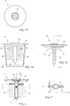
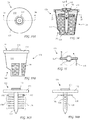
- FIG. 3A A top view of a brewing chamber accessory comprising a dynamic brewing chamber cleaner 31 according to the present invention is shown in FIG. 3A , a first side view of the dynamic brewing chamber cleaner 31 is shown in FIG. 3B and a second side view of the dynamic brewing chamber cleaner 31 rotated 90 degrees is shown in FIG. 3B .
- the dynamic brewing chamber cleaner 31 includes a lid (or disk) 32 and a column 34.
- the lid 32 serves as an adapter to position the brewing chamber cleaner with respect to the brewing chamber 29.
- a seal 33 extends up from the lid 32 to seal to the coffee maker 10 (see FIG. 2 ) to provide a flow of water 42 under pressure to the dynamic brewing chamber cleaner 31.
- the lid 32 may be configured to be held in the coffee maker in the same manner that a coffee holder lid is held in the coffee maker.
- the dynamic brewing chamber cleaner 31 may be configured to allow use in coffee makers sold under the trademark KEURIG which include a top puncture needle for injecting pressurized water into a brewing cartridge, and a bottom puncture needle for puncturing sealed brewing cartridges to extract brewed beverage. Such coffee makers are described in US Patent No. 5,325,765 .
- a pressurized flow of water 42 enters the dynamic brewing chamber cleaner 31 through a passage 47 in the lid 32.
- the passage 47 may be configured to accept the top puncture needle of the '765 patent.
- a skeleton 40 may be attached to the lid 32.
- the skeleton 40 provides a perimeter configured to cooperate with the coffee maker of the '765 patent, seating in the coffee maker to provide support for the dynamic brewing chamber cleaner 31 while avoiding the bottom puncture needle described in the '765 patent.
- FIG. 4 A cross-sectional view of the dynamic brewing chamber cleaner 31 taken along line 4-4 of FIG. 3A is shown in FIG. 4 and a cross-sectional view of the dynamic brewing chamber cleaner 31 taken along line 5-5 of FIG. 4 is shown in FIG 5 .
- a column (or dispensing member) 34 having an interior 34a is rotatable attached to the lid 32.
- the hollow column 34 includes opposing and vertically spaced apart ports (or orifices) 39 releasing radial sprays 38 of liquid (for example, water or cleaning solution) into the brewing chamber 29.
- the column 34 includes arms 35 extending radially and including ports 37 releasing tangential sprays of water 36. The tangential sprays of water 36 urge the column 34 to spin, thus cleaning the brewing chamber 29.
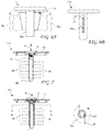
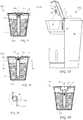
- FIG. 6A A first side view of a second dynamic brewing chamber cleaner 31a is shown in FIG. 6A and a second side view of a second dynamic brewing chamber cleaner 31a showing tangential flows 36 to rotate the column 34a is shown in FIG. 6B .
- the dynamic brewing chamber cleaner 31 includes slots 39a providing opposing sheets of water 38a for cleaning the brewing chamber, and ports 37 provide tangential flows 36 rotating the column 34a.
- the dynamic brewing chamber cleaner 31a is otherwise similar to the dynamic brewing chamber cleaner 31.
- FIG. 7 A cross-sectional view of a third dynamic brewing chamber cleaner 31b having internal propeller elements 43 is shown in FIG. 7 .
- the water flow 42 through the internal propellor elements 43 causes the column 34a to spin, thus providing dynamic water dispersion into the brewing chamber 29.
- the third dynamic brewing chamber cleaner 31b is otherwise similar to the dynamic brewing chamber cleaner 31.
- FIG. 8 A cross-sectional view of a fourth dynamic brewing chamber cleaner 31c having tangentially directed sprays is shown in FIG. 8 and a cross-sectional view of the fourth dynamic brewing chamber cleaner 31c taken along line 9-9 of FIG. 8 is shown in FIG. 9 .
- the ports 39b direct the flows 36 tangentially to rotate the column 34b which does not include the arms 35.
- the fourth dynamic brewing chamber cleaner 31c is otherwise similar to the dynamic brewing chamber cleaner 31.
- a fifth dynamic brewing chamber cleaner 31d attachable to the coffee maker nozzle 19a is shown in FIG. 10 and the coffee maker 10 with the dynamic brewing chamber cleaner 31e is shown attached to the nozzle 19a in FIG. 11 .
- the brewing chamber cleaner 31d is similar to the dynamic brewing chamber cleaner 31, but includes a bearing or bushing 52 rotatably connecting the column 34d to the nozzle 19a.
- the fifth dynamic brewing chamber cleaner 31d is otherwise similar to the dynamic brewing chamber cleaner 31.
- a coffee maker 10a including a rotating shaft 50 engaging a sixth dynamic brewing chamber cleaner 31e is shown in FIG. 12 and a cross-sectional view of the chamber cleaner 31e having a center column 34e rotated by the rotating shaft 50 is shown in FIG. 13 .
- the rotating shaft 50 engages a socket 53 to rotate the column 34e.
- the sixth dynamic brewing chamber cleaner 31e is otherwise similar to the dynamic brewing chamber cleaner 31.
- a coffee maker 10b including stator windings 52 creating a rotating stator field in a seventh dynamic chamber cleaner 31f is shown in FIG. 14 and a cross-sectional view of the dynamic brewing chamber cleaner 31f including dynamic water dispersion including magnets 54a rotated by the rotating stator field created by the coffee maker 10b is shown in FIG. 15A and a squirrel cage 54b rotated by the rotating stator field created by the coffee maker 10b is shown FIG. 15B .
- the seventh dynamic brewing chamber cleaner 31f is otherwise similar to the dynamic brewing chamber cleaner 31.
- a coffee maker 10c including an offset rotating shaft 56 engaging an eighth dynamic brewing chamber cleaner 31g including dynamic water dispersion is shown in FIG. 16 and a cross-sectional view of the dynamic brewing chamber cleaner 31g having an offset shaft 57 engaging the offset shaft 56, and gears 58 and 59 rotating the center column is shown in FIG. 17.
- the offset shafts avoid the nozzle 19a and passage 47.
- the gears 58 and 59 maybe replaced by rollers, or by a belt and hubs.
- the eighth chamber cleaner 31g is otherwise similar to the dynamic brewing chamber cleaner 31.
- FIG. 18 A cross-sectional view of a ninth dynamic brewing chamber cleaner 31h including a dome 60 for dispersing water is shown in FIG. 18 and a cross-sectional view of the dome 60 taken along line 19a-19a of FIG. 18 is shown in FIG. 19a .
- the dome 60 maybe rotated by offset tangential sprays from ports 62 similar to sprays 36 (see FIG. 5 ), or the dome 60 may be rotated by any of the means shown for brewing chamber cleaner 31a -31g.
- the dome 60 includes at least one dispersion port 64, and preferably a multiplicity of dispersion ports 64.
- the ninth chamber cleaner 31h is otherwise similar to the dynamic brewing chamber cleaner 31.
- FIG. 20 An alternative one dimensional dome 60a is shown in FIG. 20 having a single row of dispersion ports 64.
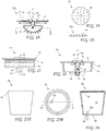
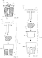
- FIG. 21 A side view of a fixed stationary chamber cleaner 31i is shown in FIG. 21 and cross-sectional view of the fixed stationary chamber cleaner 31i is shown in FIG. 22 .
- the brewing chamber cleaner 31i includes a cylindrical extension 68 reaching down into the brewing chamber.
- the cylindrical extension 68 includes at least one set of orifices 70 opening into the brewing chamber to release sprays 38 of cleaning solution.
- the orifices 70 may be radially aimed to provide a horizontal spray, or aimed partially up, or be aimed partially down providing a conical spray, preferably not exceeding 45 degrees below the horizontal.
- the orifices 70 preferably have a cross-section between 0.5mm 2 and 12mm 2 , and more preferably have a cross-section between 1.6mm2 and 10mm2, and most preferably have a cross-section of about 6mm 2 , to balance sufficient flow and intensity of the spray 38.
- the orifices 70 may be a single set at the same depth, or two or more sets spaced apart vertically at different depths.
- the brewing chamber cleaner 31i further includes a skirt 74 for guiding into the brewing chamber 29 (see FIG. 2 ).
- the skirt 74 may be tapered to simplify centering on the brewing chamber 29, and includes an annular ring 76 for retaining an extraction needle cleaner 80 (see FIGS. 23A, 23B, and 24 ), and may include annular scoring 75 providing an interference fit to the extraction needle cleaner 80.
- a rim 77 reaches radially past the skirt 74 to support the brewing chamber cleaner 31i above the brewing chamber 29.
- FIG. 23A A side view of the extraction needle cleaner 80 is shown in FIG. 23A
- a top view of the extraction needle cleaner 80 is shown in FIG. 23B
- a cross-sectional view of the extraction needle cleaner 80, taken along line 24-24 of FIG. 23B is shown in FIG. 24 .
- the extraction needle cleaner 80 is preferably a frusto conical shaped cup deep enough to capture a portion of the extraction needle 19b in an interior 83, and more preferably fits in the envelope of single serving brewing material cartridges sold under the name K_CUP®. Such single serving brewing material cartridges are disclosed in US Patent No. 7,165,488 , incorporated herein by reference.
- the extraction needle cleaner 80 includes a top portion 86 configured to engage the skirt 74 of the brewing chamber cleaner 31i (see FIG. 21 ).
- the top portion 86 may include an annular recess 82 for positive engagement with the annular ring 76 of the lid 31i, and may have a surface selected to cooperate with the annular scoring 75 on the skirt 74 to retain the attachment of the extraction needle cleaner 80 to the brewing chamber cleaner 31i.
- the extraction needle cleaner 80 may be a sturdy plastic cup including a pre-formed passage 84 aligned with the extraction needle 19b (see FIG. 2 ), and the base 81 of the extraction needle cleaner 80 may be a rubber for other flexible material to slide over the extraction needle 19b providing a seal.
- the extraction needle cleaner 80 may also be a thin plastic piece with no pre-formed passage 84, and the extraction needle 19b may pierce the plastic when the pre-formed passage 84 is inserted into the brewing chamber 19, for example, when the brewing chamber lid 14 is closed on the brewing chamber cleaner 31i with the brewing chamber 19 attached to the brewing chamber cleaner 31i.
- the cleaning liquid is sprayed out of the cylindrical extension 68 against the interior of the brewing chamber 19, thus cleaning the brewing chamber 29.
- the cleaning liquid is sprayed out of the cylindrical extension 68 filling the extraction needle cleaner 80 and washing the extraction needle 19b.
- the cleaning may be done in either order, and may be three steps, the first and third without the extraction needle cleaner 80 attached, and the second with the extraction needle cleaner 80 attached.
- a final step is preferably performed using water only to rinse the brewing chamber 29 and extraction needle 19b.
- a second brewing chamber 29a, a brewing material cartridge 28a for the brewing chamber 29a, and a brewing chamber cleaner 31j for the second brewing chamber 29a, are shown in FIG. 25 .
- the brewing material cartridge 28a resides on its side in the brewing chamber 29a and the injection needle 19a and extraction needle 29b are attached to a second brewing chamber lid 14a.
- the brewing chamber cleaner 31j includes the passage 47 for the injection needle 19a, and a second passage 47a for the extraction needle 19b.
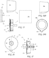
- FIG. 26 An end view of the brewing chamber cleaner 31j is shown in FIG. 26 and a cross-sectional view of the brewing chamber cleaner 31j, taken along line 27-27 of FIG. 26 , is shown in FIG. 27 .
- a lid 32a of the brewing chamber cleaner 31j includes an extended portion 32b including the passage 47a for the extraction needle 19b, and a skirt 74a providing clearance for the extraction needle 19b.
- the brewing chamber cleaner 31j is otherwise similar to the brewing chamber cleaner 31i.
- FIG. 28A A side view of an extraction needle cleaner 80a for the second brewing chamber configuration is shown in FIG. 28A and a top view of the extraction needle cleaner 80a is shown in FIG. 28B .
- the interior of the extraction needle cleaner 80a includes an extraction needle clearance area 83a providing space for the extraction needle 19b.
- the extraction needle cleaner 80a is otherwise similar to the extraction needle cleaner 80.
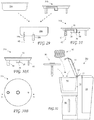
- FIG. 29 A third brewing chamber 29b configuration and a brewing chamber cleaner 31k for the third brewing chamber 29b are shown in FIG. 29 .
- the brewing chamber 29b is configured to receive a brewing cartridge 28h, for example, of the type disclosed in US Patent No. 8,087,347 .
- the '347 patent is incorporated herein by reference in its entirety.
- FIG. 30A A side view of the brewing chamber cleaner 31k is shown in FIG. 30A
- a bottom view of the brewing chamber cleaner 31k is shown in FIG. 30B
- a cross-sectional view of the brewing chamber cleaner 31k taken alone line 31-31 of FIG. 30B is shown in FIG. 31 .
- the brewing chamber cleaner 31k includes a lid portion 32, an inlet column 88, and a support member 89 to position the brewing chamber cleaner 31k in the brewing chamber 29b.
- a cylindrical extension 68 is generally centered in the brewing chamber 29b and includes orifices 70.
- the inlet column 88 includes a tapered inlet 47.
- the brewing chamber cleaner 31k is otherwise similar to the brewing chamber cleaner 31i
- a multi-cup coffee maker 90, and brewing chamber cleaner 92 for use in the multi-cup coffee maker, are shown in FIG. 32 .
- the multi-cup coffee maker 90 includes a brewing chamber 94 for receiving a portion of brewing material 93 to make a multi-cup serving of brewed beverage released into a carafe 96.
- the brewing chamber cleaner 92 preferably rests on a top edge of the brewing chamber 94, but may rest on features of the interior of the brewing chamber 94. Other than size, and positioning features, the brewing chamber cleaner 92 maybe similar to any of the brewing chamber cleaners 31-31i.
- FIG. 33A A top view of a brewing material holder 128 including a brewing chamber accessory comprising a dynamic water dispersion accessory 131 according to the present invention is shown in FIG. 33A
- a side view of the brewing material holder 128 comprising the dynamic water dispersion accessory 131 attached to a holder base 140 is shown in FIG. 33B .
- the dynamic water dispersion accessory 131 includes a lid 132 attachable to and removable from the base 140.
- a sealing portion 133 may extend up from the lid 132 to seal to the coffee maker 10 (see FIG. 2 ) to contain the flow of water 42 under pressure to the brewing material holder 128.
- the holder 128 may be configured to allow use in coffee makers sold under the trademark KEURIG which include a top puncture needle for injecting pressurized water into a brewing cartridge, and a bottom puncture needle for puncturing sealed brewing cartridges to extract brewed beverage.
- KEURIG trademark of Coffee makers sold under the trademark
- Such coffee makers are described in US Patent No. 5,325,765 , incorporated herein by reference in its entirety.
- the base 140 may further include a bottom recess 145 to avoid the bottom needle disclosed in the '765 patent.
- the recess 145 may be into the side of the holder, or into the bottom of the holder.
- an injection needle or an extraction needle may penetrate the cartridge from a side versus the top or bottom.
- the base 140 further includes mesh 144 (or the like) covered window 149 to retain the brewing material in the brewing material holder 128 during brewing, and release brewed drink from the brewing material holder 128.
- FIG. 34 A cross-sectional view of the brewing material holder 128 including dynamic water dispersion according to the present invention, along line 34-34 of FIG. 33A , is shown in FIG. 34 and a cross-sectional view of the brewing material holder 128 taken along line 35-35 of FIG. 34 is shown in FIG 35 .
- the pressurized flow of water 42 enters the brewing material holder 128 through a passage 147 in the lid 132.
- the passage 147 maybe configured to accept the top puncture needle of the '765 patent.
- a hollow, vertical, pointed column (or dispensing member) 134 is rotatable attached to the lid 132.
- the column 34 extends down into the base 140 and includes ports 139 (see FIG.
- the column 134 includes arms 135 extending radially and including ports 137 releasing tangential sprays of water 136.
- the tangential sprays of water 136 urge the column 134 to spin, thus providing dynamic water dispersion into the brewing material 141.
- FIG. 36A A side view of the lid assembly 131 the brewing material holder 128 is shown in FIG. 36A and a second side view of the lid assembly 131 rotated 90 degrees is shown in FIG. 36B .
- FIG. 37 A cross-sectional view of a second brewing material holder 128a including dynamic water dispersion having internal propeller elements 143 is shown in FIG. 37 .
- the water flow 42 through the internal propeller elements 143 causes the column 134a to spin, thus providing dynamic water dispersion into the brewing material 141.
- the second brewing material holder 128a is otherwise similar to the brewing material holder 128.
- FIG. 38 A cross-sectional view of a third brewing material holder 128b including dynamic water dispersion and having tangentially directed sprays is shown in FIG. 38 and a cross-sectional view of the third brewing material holder 128b taken along line 39-39 of FIG. 38 is shown in FIG. 39 .
- the ports 139b direct the flows 136 tangentially to rotate a second hollow, vertical, rotating column 134b, which does not include the arms 135.
- the third brewing material holder 128b is otherwise similar to the brewing material holder 128.
- FIG. 40 A cross-sectional view of a fourth brewing material holder 128c including dynamic water dispersion and having a third hollow, vertical, rotating column 134c rotatably carried by a holder base 141a is shown in FIG. 40 .
- a lid 132a guides the water flow 42 into the center column 134c.
- Mesh material 144 in walls of the base 141a allows brewed drink to escape from the holder 128c.
- the fourth brewing material holder 128c is otherwise similar to the brewing material holder 128.
- FIG. 41 An exploded view of a holder 128 with mesh material 144 in walls of a base 40a to retain brewing material 141 is shown in FIG. 41 .
- This embodiment may be used with the column 134 attached to the lid or to the base.
- FIG. 140b An exploded view of a holder 128 with a filter paper cup 145 inserted into the base 140b to retain brewing material 141.
- Windows 146 are provided in the walls and/or bottom of the base 140b to allow the brewed drink to escape, the windows 146 mayor may not include the mesh material 144.
- the column 134 is preferably attached to the lid 132 in this embodiment because a column attached to the base may interfere with the filter paper cup 145.
- a coffee maker 10a including a rotating shaft 150 for engaging a fifth brewing material holder 128d is shown in FIG. 43 and a cross-sectional view of the holder 128d having a fourth hollow, vertical, rotating column 134d rotated by the rotating shaft 150 is shown in FIG. 14 .
- a coffee maker 10b including stator windings 152 creating a rotating stator magnetic field in a sixth brewing material holder 128e is shown in FIG. 45 and a cross-sectional view of the holder 128e including dynamic water dispersion includes magnets or squirrel cage elements 154 attached to a fifth hollow, vertical, rotating column 134e and rotated by the rotating stator field created by the coffee maker 10b is shown in FIG. 46 .
- a coffee maker 10c including an offset rotating shaft 156 for engaging a seventh brewing material holder 128f including dynamic water dispersion is shown in FIG. 47 and a cross-sectional view of the brewing material holder 128f having an offset shaft 157 engaging the offset shaft 156, and a drive member 158 and driven member 159 rotating a sixth hollow, vertical, rotating 134f, is shown in FIG. 48 .
- the offset shafts avoid the nozzle 19 and passage 147.
- the driver member 158 and driven member 159 maybe gears, rollers, a belt and hubs, or the like.
- FIG. 49 A cross-sectional view of an eighth brewing material holder 128g including dynamic water dispersion having a dome 160 for dispersing water is shown in FIG. 49 and a cross-sectional view of the dome 160 taken along line 20-20 of FIG. 19 is shown in FIG. 50 .
- the dome 160 may be rotated by offset tangential sprays from ports 162 similar to sprays 136 (see FIG. 35 ), or the dome 160 may be rotated by any of the means shown for brewing material holders 128a-128f.
- the dome 160 includes at least one dispersion port 164, and preferably a multiplicity of dispersion ports 164.
- FIG. 51 An alternative one dimensional dome 160a is shown in FIG. 51 having a single row of dispersion ports 164.
- the one dimensional dome 160a may be rotated by any of the methods shown for brewing material holders 128a-128f to provide dynamic water dispersion into the brewing material.
- a brewing material holder which includes a holder base having an interior configured to hold brewing material, a removable holder lid attachable to the holder base, a water inlet in the holder lid alignable with a brewer nozzle extending down from a brewing chamber lid to receive a water flow from a brewer, a spinning dispersing member inside the brewing material holder, and passages through the rotating dispersing member in fluid communication with the water inlet and ending in ports directing sprays of water into the brewing material.
- the rotating dispersing member may be a hollow, vertical, rotating column may include a plurality of vertically spaced apart ports in fluid communication with the water flow and producing radial sprays, the column may include at least two opposing arms extending radially from the column proximal to the holder lid, each arm may include a tangential port in fluid communication with the water flow and producing tangentially sprays to rotate the column.
- the plurality of vertically spaced apart ports comprise opposing pairs of ports producing opposing radial sprays.
- the hollow, vertical, rotating column may be rotatably attached to the holder lid and include a pointed end opposite to the holder lid to facilitate pressing into brewing material in the holder base, or the hollow, vertical, rotating column may be rotatably attached to the holder base and engages the holder lid to receive the water flow.
- the rotating dispersing member may be a hollow, vertical, rotating column may include a plurality of vertically spaced apart ports in fluid communication with the water flow and producing tangential sprays to rotate the column, and may be rotatably attached to the holder lid and includes a pointed end opposite to the holder lid to facilitate pressing into brewing material in the holder base or may be rotatably attached to the holder base and engages the holder lid to receive the water flow.
- the rotating dispersing member may further be a hollow, vertical, rotating column may include a plurality of vertically spaced apart ports in fluid communication with the water flow and producing sprays into the brewing material, the column may include internal propellor elements to rotate the column when the water flow flows past the internal propellor elements.
- the rotating dispersing member may further be a hollow, vertical, rotating column may include a plurality of vertically spaced apart ports in fluid communication with the water flow and producing sprays into the brewing material, a brewing chamber lid may include a rotating member co-axial with the brewer nozzle and facing into the holder, and the column may engage the rotating member to rotate the column.
- the rotating dispersing member may be a hollow, vertical, rotating column may include a plurality of vertically spaced apart ports in fluid communication with the water flow and producing sprays into the brewing material, the brewing chamber lid includes an offset rotating member offset from the brewer nozzle and facing into the holder, the holder lid may include an offset driver member engageable with the offset rotating member and the column may include a driven member cooperating with the driver member to rotate the shaft.
- the rotating dispersing member may include a plurality of vertically spaced apart ports in fluid communication with the water flow and producing sprays into the brewing material, the holder may reside in a brewing chamber, the stator windings may surround the brewing chamber, and magnets or a squirrel cage may attached to the column, the magnets or squirrel cage may cooperate with a rotating stator magnetic field to rotate the column.
- the present invention finds industrial applicability in the field of brewed beverage.
Landscapes
- Engineering & Computer Science (AREA)
- Food Science & Technology (AREA)
- Apparatus For Making Beverages (AREA)
- Nozzles (AREA)
Claims (20)
- Brühkammer-Zubehörteil, das Folgendes umfasst:einen Deckel (32), der dafür konfiguriert ist, in einer Getränkebrühvorrichtung proximal zu einer Brühkammer-Wasserzufuhr (42) festgehalten zu werden und oberhalb einer Brühkammer aufzuliegen,einen Durchgang (47) des Deckels,eine zylindrische Verlängerung (68), die an dem Deckel befestigt ist,ein Inneres der zylindrischen Verlängerung in Fluidverbindung mit der Brühkammer-Wasserzufuhr durch den Durchgang und Öffnungen (70) in der zylindrischen Verlängerung, die eine Fluidverbindung zwischen dem Inneren der zylindrischen Verlängerung und der Brühkammer bereitstellen, wobei die Öffnungen dafür angeordnet und bemessen sind, den Flüssigkeitsstrom durch die Öffnungen in die Brühkammer zu sprühen,eine Schürze (74), die von dem Deckel aus nach unten reicht,einen Ring (76), der sich von dem Deckel aus in Radialrichtung, über die Schürze hinaus, erstreckt, zum Stützen des Brühkammer-Zubehörteils in der Brühkammer,wobei die zylindrische Verlängerung wenigstens einen Satz von Öffnungen einschließt, die sich in die Brühkammer öffnen, um Sprühnebel (38) einer Reinigungslösung freizusetzen,wobei die zylindrische Verlängerung derart nach unten in die Brühkammer reicht, dass der Durchgang eine Fluidverbindung (42) von dem Oberteil des Deckels bis zu dem wenigstens einen Satz von Öffnungen durch den Durchgang der zylindrischen Verlängerung bereitstellt.
- Brühkammerreiniger nach Anspruch 1, wobei die Schürze einen unteren nach innen verjüngten Abschnitt zum Zentrieren des Brühkammerreinigers in der Brühkammer einschließt.
- Brühkammerreiniger nach Anspruch 2, der ferner Folgendes einschließt:einen Extraktionsnadelreiniger (80), der einen Becher umfasst, der an dem Deckel befestigt werden kann, undwobei der Becher ausreichend tief ist, um einen Abschnitt einer Extraktionsnadel (19b) in einem Inneren des Extraktionsnadelreinigers aufzunehmen.
- Brühkammerreiniger nach Anspruch 3, wobei: die Schürze einen äußeren ringförmigen Ring einschließt und
ein oberer Abschnitt des Extraktionsnadelreinigers einen inneren ringförmigen Ring einschließt, der dafür konfiguriert ist, den äußeren ringförmigen Ring in Eingriff zu nehmen, um den Extraktionsnadelreiniger an der Schürze festzuhalten. - Brühkammerreiniger nach Anspruch 4, wobei:die Schürze eine ringförmige Einkerbung (75) einschließt undein oberer Abschnitt des Extraktionsnadelreinigers eine Innenfläche einschließt, die dafür konfiguriert ist, eine Presspassung mit der ringförmigen Einkerbung bereitzustellen, um den Extraktionsnadelreiniger an der Schürze festzuhalten.
- Brühkammerreiniger nach einem der Ansprüche 1 bis 5, wobei der Extraktionsnadelreiniger ein robuster Kunststoffbecher ist, der einen vorgeformten Durchgang 84 einschließt, der mit der Extraktionsnadel 19b ausgerichtet ist.
- Brühkammerreiniger nach Anspruch 6, wobei die Basis 81 des Extraktionsnadelreinigers aus einem flexiblen Material besteht, um ein Gleiten über die Extraktionsnadel 19b zu ermöglichen, wodurch eine Dichtung bereitgestellt wird.
- Brühkammerreiniger nach Anspruch 7, wobei das flexible Material Gummi ist.
- Brühkammerreiniger nach Anspruch 1, wobei die zylindrische Verlängerung fest an dem Deckel befestigt ist.
- Brühkammerreiniger nach Anspruch 1, wobei das Abgabeelement drehbar an dem Deckel befestigt ist, um einen sich drehenden Sprühnebel bereitzustellen.
- Brühkammerreiniger nach Anspruch 10, wobei wenigstens ein Sprühnebel von dem Abgabeelement wenigstens teilweise tangential ist, um das Abgabeelement zu drehen.
- Brühkammerreiniger nach Anspruch 11, wobei das Abgabeelement innere Propellerelemente einschließt, um das Abgabeelement zu drehen.
- Brühkammerreiniger nach Anspruch 10, wobei die Kaffeemaschine eine sich drehende Welle einschließt, um das Abgabeelement zu drehen.
- Brühkammerreiniger nach Anspruch 10, wobei die Kaffeemaschine eine elektrische Spule um die Brühkammer einschließt und das Abgabeelement Magnete (54a) einschließt, um das Abgabeelement zu drehen.
- Brühkammerreiniger nach Anspruch 10, wobei die Kaffeemaschine eine elektrische Spule um die Brühkammer einschließt und das Abgabeelement einen elektrisch leitenden Käfigläufer (54b) einschließt, um das Abgabeelement zu drehen.
- Brühkammerreiniger nach Anspruch 1, wobei das Abgabeelement radial gerichtete Öffnungen schließt, die einen horizontalen Sprühnebel in die Brühkammer bereitstellen.
- Brühkammerreiniger nach Anspruch 1, wobei das Abgabeelement nach unten gerichtete Öffnungen schließt, die einen kegelförmigen Sprühnebel in die Brühkammer bereitstellen.
- Brühkammerreiniger nach Anspruch 1, wobei die Öffnungen eine Gesamtquerschnittsfläche zwischen 0,5 mm2 und 12 mm2 aufweisen.
- Brühkammerreiniger nach Anspruch 1, wobei die Öffnungen eine Gesamtquerschnittsfläche zwischen 1,6 mm2 und 10 mm2 aufweisen.
- Brühkammerreiniger nach Anspruch 1, wobei die Öffnungen eine Gesamtquerschnittsfläche von etwa 6 mm2 aufweisen.
Applications Claiming Priority (5)
| Application Number | Priority Date | Filing Date | Title |
|---|---|---|---|
| US201562249047P | 2015-10-30 | 2015-10-30 | |
| US201562249009P | 2015-10-30 | 2015-10-30 | |
| US15/191,259 US10702096B2 (en) | 2015-10-30 | 2016-06-23 | Brewing chamber cleaner |
| US15/338,357 US9962031B2 (en) | 2015-10-30 | 2016-10-29 | Brewing chamber with dynamic water dispersion |
| PCT/US2016/059621 WO2017075560A2 (en) | 2015-10-30 | 2016-10-30 | Dynamic water dispersion and brewing chamber cleaner |
Publications (3)
| Publication Number | Publication Date |
|---|---|
| EP3367854A2 EP3367854A2 (de) | 2018-09-05 |
| EP3367854A4 EP3367854A4 (de) | 2019-06-12 |
| EP3367854B1 true EP3367854B1 (de) | 2021-07-28 |
Family
ID=62819503
Family Applications (1)
| Application Number | Title | Priority Date | Filing Date |
|---|---|---|---|
| EP16861024.4A Active EP3367854B1 (de) | 2015-10-30 | 2016-10-30 | Dynamische wasserdispersion und braukammerreiniger |
Country Status (2)
| Country | Link |
|---|---|
| EP (1) | EP3367854B1 (de) |
| CN (1) | CN108289566B (de) |
Families Citing this family (2)
| Publication number | Priority date | Publication date | Assignee | Title |
|---|---|---|---|---|
| CN110664257A (zh) * | 2019-09-27 | 2020-01-10 | 珠海市卡法利尔科技有限公司 | 一种咖啡机及其冲泡装置 |
| AU2020395870B2 (en) * | 2019-12-04 | 2026-02-19 | Société des Produits Nestlé S.A. | A cleaning apparatus for a beverage preparation machine |
Family Cites Families (19)
| Publication number | Priority date | Publication date | Assignee | Title |
|---|---|---|---|---|
| US5255593A (en) * | 1991-04-10 | 1993-10-26 | Bunn-O-Matic Corporation | Automatic brewer |
| JP2002223922A (ja) * | 2001-02-07 | 2002-08-13 | Doutor Coffee Co Ltd | ティーポット |
| US7509908B1 (en) * | 2004-04-02 | 2009-03-31 | Food Equipment Technologies Company, Inc. | Beverage brewer with sliding tube brew valve assembly |
| DE202004020907U1 (de) * | 2004-09-24 | 2006-05-24 | BSH Bosch und Siemens Hausgeräte GmbH | Kaffeemaschine |
| NL2000494C2 (nl) * | 2006-03-21 | 2009-01-20 | Dong-Lei Wang | Schuiminrichting in een koffiemachine. |
| DE202007008813U1 (de) * | 2007-06-21 | 2007-11-29 | Mahlich, Gotthard | Getränkezubereitungsgerät |
| US20120070542A1 (en) * | 2010-09-16 | 2012-03-22 | Starbucks Corporation D/B/A Starbucks Coffee Company | Instant beverage cartridges and methods |
| CN201481108U (zh) * | 2009-05-11 | 2010-05-26 | 杜伟 | 可更换咖啡胶囊固定器的咖啡胶囊酿造装置 |
| US9167932B2 (en) * | 2009-09-28 | 2015-10-27 | Food Equipment Technologies Company, Inc. | Dual-purpose brewer and brew basket and method of brewing |
| US10071851B2 (en) * | 2010-07-12 | 2018-09-11 | Robert Bao Vu | Apparatus and products for producing beverages, and methods for making and using same |
| CN201822645U (zh) * | 2010-09-26 | 2011-05-11 | 广东新宝电器股份有限公司 | 咖啡机的冲泡机构 |
| KR101268212B1 (ko) * | 2011-04-29 | 2013-05-27 | 김광환 | 밥솥용 물 계량컵 |
| DE102011115833A1 (de) * | 2011-10-13 | 2013-04-18 | K-Fee System Gmbh | Portionskapsel zur Herstellung eines Getränks mit einer Portionskapsel |
| CN202396332U (zh) * | 2011-11-17 | 2012-08-29 | 大千生态景观股份有限公司 | 注射喷洒一体化打药机 |
| US9227778B2 (en) * | 2012-12-11 | 2016-01-05 | Victor M. Aviles | Beverage cartridge |
| CN103054469A (zh) * | 2012-12-26 | 2013-04-24 | 宁波绿之品电器科技有限公司 | 搅拌式泡茶机 |
| US9375114B2 (en) * | 2013-05-22 | 2016-06-28 | Sunbeam Products, Inc. | Hot beverage maker with cleaning apparatus and related method |
| JP6434042B2 (ja) * | 2014-02-14 | 2018-12-05 | レミントン デザインズ リミテッド ライアビリティ カンパニー | 飲料抽出装置および飲料の抽出に関連する方法 |
| CN204617922U (zh) * | 2015-04-23 | 2015-09-09 | 广东美的生活电器制造有限公司 | 饮料机系统 |
-
2016
- 2016-10-30 EP EP16861024.4A patent/EP3367854B1/de active Active
- 2016-10-30 CN CN201680070446.9A patent/CN108289566B/zh active Active
Also Published As
| Publication number | Publication date |
|---|---|
| CN108289566B (zh) | 2023-03-28 |
| EP3367854A2 (de) | 2018-09-05 |
| HK1254732A1 (zh) | 2019-07-26 |
| CN108289566A (zh) | 2018-07-17 |
| EP3367854A4 (de) | 2019-06-12 |
Similar Documents
| Publication | Publication Date | Title |
|---|---|---|
| US10702096B2 (en) | Brewing chamber cleaner | |
| KR101479082B1 (ko) | 음료 추출 기기 및 방법 | |
| KR101591771B1 (ko) | 음료 추출 기기 | |
| CN104203054B (zh) | 胶囊适配器和使用所述胶囊适配器的系统 | |
| CN114680623B (zh) | 用于制备冲泡的饮品的系统和在系统中使用的筒转接器 | |
| US9907425B2 (en) | Reusable brewing cartridge | |
| US9999316B2 (en) | Beverage substance cartridge, water filling apparatus, beverage producing equipment, beverage producing system and beverage producing method | |
| US10455972B2 (en) | Beverage brewer with brewing rotation | |
| EP2168468A1 (de) | Vorrichtung zur Zubereitung eines Getränks in einer Tasse | |
| US11638499B2 (en) | Beverage brewer spray apparatus having multiple dispersion members | |
| WO2014011324A1 (en) | Hybrid coffee maker with multiple brewing modes | |
| US9788682B2 (en) | Beverage brewing device for automatically brewing and dispensing single cup quantities of beverage through a vending machine with minimal manual participation | |
| KR20130081722A (ko) | 음료 추출 기기 및 방법 | |
| KR20160127011A (ko) | 식품 제조 기계를 위한 브루잉 유닛 | |
| EP2907425B1 (de) | Maschine zur Herstellung eines Brühgetränks und Brühgruppe | |
| US20230180963A1 (en) | Brewing Machine Cleaner | |
| EP3367854A2 (de) | Dynamische wasserdispersion und braukammerreiniger | |
| WO2017075560A2 (en) | Dynamic water dispersion and brewing chamber cleaner | |
| US10426289B2 (en) | Brewing material holder with a top water spray | |
| US12185867B2 (en) | Beverage brewer spray apparatus having accommodation for multiple dispersion members | |
| US20200288908A1 (en) | Brewing Machine Cleaner | |
| US9962031B2 (en) | Brewing chamber with dynamic water dispersion | |
| HK1254732B (en) | Dynamic water dispersion and brewing chamber cleaner | |
| US20200069108A1 (en) | Liquid-Dispersing Member for a Brewing Material Holder | |
| US20240366023A1 (en) | Dispersion Apparatus for a Brewing Material Holder |
Legal Events
| Date | Code | Title | Description |
|---|---|---|---|
| STAA | Information on the status of an ep patent application or granted ep patent |
Free format text: STATUS: THE INTERNATIONAL PUBLICATION HAS BEEN MADE |
|
| PUAI | Public reference made under article 153(3) epc to a published international application that has entered the european phase |
Free format text: ORIGINAL CODE: 0009012 |
|
| STAA | Information on the status of an ep patent application or granted ep patent |
Free format text: STATUS: REQUEST FOR EXAMINATION WAS MADE |
|
| 17P | Request for examination filed |
Effective date: 20180530 |
|
| AK | Designated contracting states |
Kind code of ref document: A2 Designated state(s): AL AT BE BG CH CY CZ DE DK EE ES FI FR GB GR HR HU IE IS IT LI LT LU LV MC MK MT NL NO PL PT RO RS SE SI SK SM TR |
|
| AX | Request for extension of the european patent |
Extension state: BA ME |
|
| DAV | Request for validation of the european patent (deleted) | ||
| DAX | Request for extension of the european patent (deleted) | ||
| A4 | Supplementary search report drawn up and despatched |
Effective date: 20190509 |
|
| RIC1 | Information provided on ipc code assigned before grant |
Ipc: A47J 31/60 20060101ALI20190503BHEP Ipc: A47J 31/46 20060101ALI20190503BHEP Ipc: A47J 31/40 20060101AFI20190503BHEP |
|
| REG | Reference to a national code |
Ref country code: HK Ref legal event code: DE Ref document number: 1254732 Country of ref document: HK |
|
| RIC1 | Information provided on ipc code assigned before grant |
Ipc: A47J 31/40 20060101AFI20201221BHEP Ipc: A47J 31/60 20060101ALI20201221BHEP Ipc: A47J 31/46 20060101ALI20201221BHEP |
|
| GRAP | Despatch of communication of intention to grant a patent |
Free format text: ORIGINAL CODE: EPIDOSNIGR1 |
|
| STAA | Information on the status of an ep patent application or granted ep patent |
Free format text: STATUS: GRANT OF PATENT IS INTENDED |
|
| INTG | Intention to grant announced |
Effective date: 20210226 |
|
| GRAS | Grant fee paid |
Free format text: ORIGINAL CODE: EPIDOSNIGR3 |
|
| GRAA | (expected) grant |
Free format text: ORIGINAL CODE: 0009210 |
|
| STAA | Information on the status of an ep patent application or granted ep patent |
Free format text: STATUS: THE PATENT HAS BEEN GRANTED |
|
| AK | Designated contracting states |
Kind code of ref document: B1 Designated state(s): AL AT BE BG CH CY CZ DE DK EE ES FI FR GB GR HR HU IE IS IT LI LT LU LV MC MK MT NL NO PL PT RO RS SE SI SK SM TR |
|
| REG | Reference to a national code |
Ref country code: GB Ref legal event code: FG4D |
|
| REG | Reference to a national code |
Ref country code: CH Ref legal event code: EP |
|
| REG | Reference to a national code |
Ref country code: DE Ref legal event code: R096 Ref document number: 602016061385 Country of ref document: DE |
|
| REG | Reference to a national code |
Ref country code: AT Ref legal event code: REF Ref document number: 1413929 Country of ref document: AT Kind code of ref document: T Effective date: 20210815 |
|
| REG | Reference to a national code |
Ref country code: IE Ref legal event code: FG4D |
|
| REG | Reference to a national code |
Ref country code: LT Ref legal event code: MG9D |
|
| REG | Reference to a national code |
Ref country code: NL Ref legal event code: MP Effective date: 20210728 |
|
| REG | Reference to a national code |
Ref country code: AT Ref legal event code: MK05 Ref document number: 1413929 Country of ref document: AT Kind code of ref document: T Effective date: 20210728 |
|
| PG25 | Lapsed in a contracting state [announced via postgrant information from national office to epo] |
Ref country code: NL Free format text: LAPSE BECAUSE OF FAILURE TO SUBMIT A TRANSLATION OF THE DESCRIPTION OR TO PAY THE FEE WITHIN THE PRESCRIBED TIME-LIMIT Effective date: 20210728 Ref country code: PT Free format text: LAPSE BECAUSE OF FAILURE TO SUBMIT A TRANSLATION OF THE DESCRIPTION OR TO PAY THE FEE WITHIN THE PRESCRIBED TIME-LIMIT Effective date: 20211129 Ref country code: NO Free format text: LAPSE BECAUSE OF FAILURE TO SUBMIT A TRANSLATION OF THE DESCRIPTION OR TO PAY THE FEE WITHIN THE PRESCRIBED TIME-LIMIT Effective date: 20211028 Ref country code: HR Free format text: LAPSE BECAUSE OF FAILURE TO SUBMIT A TRANSLATION OF THE DESCRIPTION OR TO PAY THE FEE WITHIN THE PRESCRIBED TIME-LIMIT Effective date: 20210728 Ref country code: ES Free format text: LAPSE BECAUSE OF FAILURE TO SUBMIT A TRANSLATION OF THE DESCRIPTION OR TO PAY THE FEE WITHIN THE PRESCRIBED TIME-LIMIT Effective date: 20210728 Ref country code: FI Free format text: LAPSE BECAUSE OF FAILURE TO SUBMIT A TRANSLATION OF THE DESCRIPTION OR TO PAY THE FEE WITHIN THE PRESCRIBED TIME-LIMIT Effective date: 20210728 Ref country code: LT Free format text: LAPSE BECAUSE OF FAILURE TO SUBMIT A TRANSLATION OF THE DESCRIPTION OR TO PAY THE FEE WITHIN THE PRESCRIBED TIME-LIMIT Effective date: 20210728 Ref country code: BG Free format text: LAPSE BECAUSE OF FAILURE TO SUBMIT A TRANSLATION OF THE DESCRIPTION OR TO PAY THE FEE WITHIN THE PRESCRIBED TIME-LIMIT Effective date: 20211028 Ref country code: AT Free format text: LAPSE BECAUSE OF FAILURE TO SUBMIT A TRANSLATION OF THE DESCRIPTION OR TO PAY THE FEE WITHIN THE PRESCRIBED TIME-LIMIT Effective date: 20210728 Ref country code: RS Free format text: LAPSE BECAUSE OF FAILURE TO SUBMIT A TRANSLATION OF THE DESCRIPTION OR TO PAY THE FEE WITHIN THE PRESCRIBED TIME-LIMIT Effective date: 20210728 Ref country code: SE Free format text: LAPSE BECAUSE OF FAILURE TO SUBMIT A TRANSLATION OF THE DESCRIPTION OR TO PAY THE FEE WITHIN THE PRESCRIBED TIME-LIMIT Effective date: 20210728 |
|
| PG25 | Lapsed in a contracting state [announced via postgrant information from national office to epo] |
Ref country code: PL Free format text: LAPSE BECAUSE OF FAILURE TO SUBMIT A TRANSLATION OF THE DESCRIPTION OR TO PAY THE FEE WITHIN THE PRESCRIBED TIME-LIMIT Effective date: 20210728 Ref country code: LV Free format text: LAPSE BECAUSE OF FAILURE TO SUBMIT A TRANSLATION OF THE DESCRIPTION OR TO PAY THE FEE WITHIN THE PRESCRIBED TIME-LIMIT Effective date: 20210728 Ref country code: GR Free format text: LAPSE BECAUSE OF FAILURE TO SUBMIT A TRANSLATION OF THE DESCRIPTION OR TO PAY THE FEE WITHIN THE PRESCRIBED TIME-LIMIT Effective date: 20211029 |
|
| PG25 | Lapsed in a contracting state [announced via postgrant information from national office to epo] |
Ref country code: DK Free format text: LAPSE BECAUSE OF FAILURE TO SUBMIT A TRANSLATION OF THE DESCRIPTION OR TO PAY THE FEE WITHIN THE PRESCRIBED TIME-LIMIT Effective date: 20210728 |
|
| REG | Reference to a national code |
Ref country code: DE Ref legal event code: R097 Ref document number: 602016061385 Country of ref document: DE |
|
| PG25 | Lapsed in a contracting state [announced via postgrant information from national office to epo] |
Ref country code: SM Free format text: LAPSE BECAUSE OF FAILURE TO SUBMIT A TRANSLATION OF THE DESCRIPTION OR TO PAY THE FEE WITHIN THE PRESCRIBED TIME-LIMIT Effective date: 20210728 Ref country code: SK Free format text: LAPSE BECAUSE OF FAILURE TO SUBMIT A TRANSLATION OF THE DESCRIPTION OR TO PAY THE FEE WITHIN THE PRESCRIBED TIME-LIMIT Effective date: 20210728 Ref country code: RO Free format text: LAPSE BECAUSE OF FAILURE TO SUBMIT A TRANSLATION OF THE DESCRIPTION OR TO PAY THE FEE WITHIN THE PRESCRIBED TIME-LIMIT Effective date: 20210728 Ref country code: EE Free format text: LAPSE BECAUSE OF FAILURE TO SUBMIT A TRANSLATION OF THE DESCRIPTION OR TO PAY THE FEE WITHIN THE PRESCRIBED TIME-LIMIT Effective date: 20210728 Ref country code: CZ Free format text: LAPSE BECAUSE OF FAILURE TO SUBMIT A TRANSLATION OF THE DESCRIPTION OR TO PAY THE FEE WITHIN THE PRESCRIBED TIME-LIMIT Effective date: 20210728 Ref country code: AL Free format text: LAPSE BECAUSE OF FAILURE TO SUBMIT A TRANSLATION OF THE DESCRIPTION OR TO PAY THE FEE WITHIN THE PRESCRIBED TIME-LIMIT Effective date: 20210728 |
|
| PLBE | No opposition filed within time limit |
Free format text: ORIGINAL CODE: 0009261 |
|
| STAA | Information on the status of an ep patent application or granted ep patent |
Free format text: STATUS: NO OPPOSITION FILED WITHIN TIME LIMIT |
|
| REG | Reference to a national code |
Ref country code: CH Ref legal event code: PL |
|
| REG | Reference to a national code |
Ref country code: BE Ref legal event code: MM Effective date: 20211031 |
|
| PG25 | Lapsed in a contracting state [announced via postgrant information from national office to epo] |
Ref country code: MC Free format text: LAPSE BECAUSE OF FAILURE TO SUBMIT A TRANSLATION OF THE DESCRIPTION OR TO PAY THE FEE WITHIN THE PRESCRIBED TIME-LIMIT Effective date: 20210728 |
|
| 26N | No opposition filed |
Effective date: 20220429 |
|
| PG25 | Lapsed in a contracting state [announced via postgrant information from national office to epo] |
Ref country code: LU Free format text: LAPSE BECAUSE OF NON-PAYMENT OF DUE FEES Effective date: 20211030 Ref country code: IT Free format text: LAPSE BECAUSE OF FAILURE TO SUBMIT A TRANSLATION OF THE DESCRIPTION OR TO PAY THE FEE WITHIN THE PRESCRIBED TIME-LIMIT Effective date: 20210728 Ref country code: BE Free format text: LAPSE BECAUSE OF NON-PAYMENT OF DUE FEES Effective date: 20211031 |
|
| PG25 | Lapsed in a contracting state [announced via postgrant information from national office to epo] |
Ref country code: LI Free format text: LAPSE BECAUSE OF NON-PAYMENT OF DUE FEES Effective date: 20211031 Ref country code: CH Free format text: LAPSE BECAUSE OF NON-PAYMENT OF DUE FEES Effective date: 20211031 |
|
| PG25 | Lapsed in a contracting state [announced via postgrant information from national office to epo] |
Ref country code: IE Free format text: LAPSE BECAUSE OF NON-PAYMENT OF DUE FEES Effective date: 20211030 |
|
| PG25 | Lapsed in a contracting state [announced via postgrant information from national office to epo] |
Ref country code: HU Free format text: LAPSE BECAUSE OF FAILURE TO SUBMIT A TRANSLATION OF THE DESCRIPTION OR TO PAY THE FEE WITHIN THE PRESCRIBED TIME-LIMIT; INVALID AB INITIO Effective date: 20161030 |
|
| PG25 | Lapsed in a contracting state [announced via postgrant information from national office to epo] |
Ref country code: CY Free format text: LAPSE BECAUSE OF FAILURE TO SUBMIT A TRANSLATION OF THE DESCRIPTION OR TO PAY THE FEE WITHIN THE PRESCRIBED TIME-LIMIT Effective date: 20210728 |
|
| PG25 | Lapsed in a contracting state [announced via postgrant information from national office to epo] |
Ref country code: MK Free format text: LAPSE BECAUSE OF FAILURE TO SUBMIT A TRANSLATION OF THE DESCRIPTION OR TO PAY THE FEE WITHIN THE PRESCRIBED TIME-LIMIT Effective date: 20210728 |
|
| PG25 | Lapsed in a contracting state [announced via postgrant information from national office to epo] |
Ref country code: TR Free format text: LAPSE BECAUSE OF FAILURE TO SUBMIT A TRANSLATION OF THE DESCRIPTION OR TO PAY THE FEE WITHIN THE PRESCRIBED TIME-LIMIT Effective date: 20210728 |
|
| PG25 | Lapsed in a contracting state [announced via postgrant information from national office to epo] |
Ref country code: MT Free format text: LAPSE BECAUSE OF FAILURE TO SUBMIT A TRANSLATION OF THE DESCRIPTION OR TO PAY THE FEE WITHIN THE PRESCRIBED TIME-LIMIT Effective date: 20210728 |
|
| PGFP | Annual fee paid to national office [announced via postgrant information from national office to epo] |
Ref country code: DE Payment date: 20241014 Year of fee payment: 9 |
|
| PGFP | Annual fee paid to national office [announced via postgrant information from national office to epo] |
Ref country code: GB Payment date: 20241010 Year of fee payment: 9 |
|
| PGFP | Annual fee paid to national office [announced via postgrant information from national office to epo] |
Ref country code: FR Payment date: 20241010 Year of fee payment: 9 |