EP3368146B1 - Elektrodenpositionierungssystem - Google Patents
Elektrodenpositionierungssystem Download PDFInfo
- Publication number
- EP3368146B1 EP3368146B1 EP16860711.7A EP16860711A EP3368146B1 EP 3368146 B1 EP3368146 B1 EP 3368146B1 EP 16860711 A EP16860711 A EP 16860711A EP 3368146 B1 EP3368146 B1 EP 3368146B1
- Authority
- EP
- European Patent Office
- Prior art keywords
- bridge
- user
- pair
- band
- electrode
- Prior art date
- Legal status (The legal status is an assumption and is not a legal conclusion. Google has not performed a legal analysis and makes no representation as to the accuracy of the status listed.)
- Active
Links
Images








Classifications
-
- A—HUMAN NECESSITIES
- A61—MEDICAL OR VETERINARY SCIENCE; HYGIENE
- A61N—ELECTROTHERAPY; MAGNETOTHERAPY; RADIATION THERAPY; ULTRASOUND THERAPY
- A61N1/00—Electrotherapy; Circuits therefor
- A61N1/02—Details
- A61N1/04—Electrodes
- A61N1/0404—Electrodes for external use
- A61N1/0472—Structure-related aspects
- A61N1/0476—Array electrodes (including any electrode arrangement with more than one electrode for at least one of the polarities)
-
- A—HUMAN NECESSITIES
- A61—MEDICAL OR VETERINARY SCIENCE; HYGIENE
- A61B—DIAGNOSIS; SURGERY; IDENTIFICATION
- A61B5/00—Measuring for diagnostic purposes; Identification of persons
- A61B5/68—Arrangements of detecting, measuring or recording means, e.g. sensors, in relation to patient
- A61B5/6801—Arrangements of detecting, measuring or recording means, e.g. sensors, in relation to patient specially adapted to be attached to or worn on the body surface
- A61B5/6802—Sensor mounted on worn items
- A61B5/6803—Head-worn items, e.g. helmets, masks, headphones or goggles
-
- A—HUMAN NECESSITIES
- A61—MEDICAL OR VETERINARY SCIENCE; HYGIENE
- A61B—DIAGNOSIS; SURGERY; IDENTIFICATION
- A61B5/00—Measuring for diagnostic purposes; Identification of persons
- A61B5/68—Arrangements of detecting, measuring or recording means, e.g. sensors, in relation to patient
- A61B5/6801—Arrangements of detecting, measuring or recording means, e.g. sensors, in relation to patient specially adapted to be attached to or worn on the body surface
- A61B5/6813—Specially adapted to be attached to a specific body part
- A61B5/6814—Head
-
- A—HUMAN NECESSITIES
- A61—MEDICAL OR VETERINARY SCIENCE; HYGIENE
- A61N—ELECTROTHERAPY; MAGNETOTHERAPY; RADIATION THERAPY; ULTRASOUND THERAPY
- A61N1/00—Electrotherapy; Circuits therefor
- A61N1/02—Details
- A61N1/04—Electrodes
- A61N1/0404—Electrodes for external use
- A61N1/0408—Use-related aspects
- A61N1/0456—Specially adapted for transcutaneous electrical nerve stimulation [TENS]
-
- A—HUMAN NECESSITIES
- A61—MEDICAL OR VETERINARY SCIENCE; HYGIENE
- A61N—ELECTROTHERAPY; MAGNETOTHERAPY; RADIATION THERAPY; ULTRASOUND THERAPY
- A61N1/00—Electrotherapy; Circuits therefor
- A61N1/18—Applying electric currents by contact electrodes
- A61N1/32—Applying electric currents by contact electrodes alternating or intermittent currents
- A61N1/36—Applying electric currents by contact electrodes alternating or intermittent currents for stimulation
- A61N1/36014—External stimulators, e.g. with patch electrodes
- A61N1/36025—External stimulators, e.g. with patch electrodes for treating a mental or cerebral condition
-
- A—HUMAN NECESSITIES
- A61—MEDICAL OR VETERINARY SCIENCE; HYGIENE
- A61N—ELECTROTHERAPY; MAGNETOTHERAPY; RADIATION THERAPY; ULTRASOUND THERAPY
- A61N1/00—Electrotherapy; Circuits therefor
- A61N1/02—Details
- A61N1/04—Electrodes
- A61N1/0404—Electrodes for external use
- A61N1/0472—Structure-related aspects
- A61N1/0484—Garment electrodes worn by the patient
-
- A—HUMAN NECESSITIES
- A61—MEDICAL OR VETERINARY SCIENCE; HYGIENE
- A61N—ELECTROTHERAPY; MAGNETOTHERAPY; RADIATION THERAPY; ULTRASOUND THERAPY
- A61N1/00—Electrotherapy; Circuits therefor
- A61N1/02—Details
- A61N1/04—Electrodes
- A61N1/0404—Electrodes for external use
- A61N1/0472—Structure-related aspects
- A61N1/0492—Patch electrodes
-
- H—ELECTRICITY
- H04—ELECTRIC COMMUNICATION TECHNIQUE
- H04R—LOUDSPEAKERS, MICROPHONES, GRAMOPHONE PICK-UPS OR LIKE ACOUSTIC ELECTROMECHANICAL TRANSDUCERS; ELECTRIC HEARING AIDS; PUBLIC ADDRESS SYSTEMS
- H04R1/00—Details of transducers, loudspeakers or microphones
- H04R1/10—Earpieces; Attachments therefor ; Earphones; Monophonic headphones
- H04R1/1058—Manufacture or assembly
-
- H—ELECTRICITY
- H04—ELECTRIC COMMUNICATION TECHNIQUE
- H04R—LOUDSPEAKERS, MICROPHONES, GRAMOPHONE PICK-UPS OR LIKE ACOUSTIC ELECTROMECHANICAL TRANSDUCERS; ELECTRIC HEARING AIDS; PUBLIC ADDRESS SYSTEMS
- H04R2460/00—Details of hearing devices, i.e. of ear- or headphones covered by H04R1/10 or H04R5/033 but not provided for in any of their subgroups, or of hearing aids covered by H04R25/00 but not provided for in any of its subgroups
- H04R2460/13—Hearing devices using bone conduction transducers
-
- H—ELECTRICITY
- H04—ELECTRIC COMMUNICATION TECHNIQUE
- H04R—LOUDSPEAKERS, MICROPHONES, GRAMOPHONE PICK-UPS OR LIKE ACOUSTIC ELECTROMECHANICAL TRANSDUCERS; ELECTRIC HEARING AIDS; PUBLIC ADDRESS SYSTEMS
- H04R5/00—Stereophonic arrangements
- H04R5/033—Headphones for stereophonic communication
-
- H—ELECTRICITY
- H04—ELECTRIC COMMUNICATION TECHNIQUE
- H04R—LOUDSPEAKERS, MICROPHONES, GRAMOPHONE PICK-UPS OR LIKE ACOUSTIC ELECTROMECHANICAL TRANSDUCERS; ELECTRIC HEARING AIDS; PUBLIC ADDRESS SYSTEMS
- H04R5/00—Stereophonic arrangements
- H04R5/033—Headphones for stereophonic communication
- H04R5/0335—Earpiece support, e.g. headbands or neckrests
Definitions
- This invention relates generally to the biosignals field, and more specifically to a new and useful electrode positioning system.
- Electrode systems in the biosignals field are used to transmit electrical signals to a subject, and can be used to detect or measure biosignals from the subject.
- Current electrode systems for electrical stimulation and/or biosignal detection are, however, insufficient for many reasons including inadequate contact between the subject and the electrode(s) of a system, non-robust contact between the subject and the electrode(s) of a system, inadequate accommodation of individual anatomical variation across subjects, subject discomfort while using an electrode system, and/or limited use within multiple electrical simulation or biosignal detection paradigms.
- current systems and methods generally fail to allow a user to properly position electrodes at a head region by him/herself in a non-clinical or non-research environment. Examples of electrode positioning systems are disclosed in US 2012/226127A1 , US 2014/350431A1 and US 2015/065838A1 .
- This invention provides a system for transcranially stimulation of a user as defined in claim 1.
- Preferred embodiments are defined by the dependent claims.
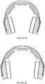
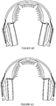
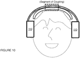
- An embodiment of a system 100 for stimulating a user and operable at a head region of the user includes: a set of pads 110a configured at opposing head regions of the user during use of the system; a band 120a having a first end coupled to a first pad of the set of pads and a second end coupled to a second pad of the set of pads; a bridge 130a coupled the band and to an electrode 140a during use of the system; and a set of links 150a associated with the set of pads 110a, each of the set of links coupled at a first region to an interior portion of its corresponding pad, and coupled at a second region to the bridge, having an elastic modulus above a threshold modulus such that: in a first operation mode, lateral displacement of the set of pads 110 produces lateral displacement of the electrode away from the head region of the user, and in a second operation mode, release of the set of pads orients protrusions of the electrode approximately normal to the head region of the user.
- the system 100 can comprise: a set of ear pad modules 110 configured to provide a pair of anchoring points at contralateral head regions of the user; a band 120 having a first end coupled to a first ear pad module of the set of ear pad modules 110 and a second end coupled to a second ear pad module of the set of ear pad modules 110; a bridge 130 coupled to an inferior midregion of the band 120 and configured to house a set of electrodes 140 for providing electrical stimulation to the user; a set of structural links providing paths for transmitting electrical current to the set of electrodes, the set of structural links 150 coupled to interior portions of the set of ear pad modules and having an elastic modulus above a threshold modulus such that 1) in a first operation mode, lateral displacement of the set of ear pad modules 110 by the user produces lateral displacement of the set of electrodes 140 away from the head region of the user, and 2) in a second operation mode, release of the set of ear pad modules 110 by the user orients protrusions of
- the system 100 can additionally or alternatively incorporate or cooperate with one or more of: transducers (e.g., optical sensors, optical emitters, ultrasonic transducers, etc.), additional sensors (e.g., temperature sensors, activity detecting sensors, sensors associated with position, velocity, or acceleration detection, biometric sensors, etc.) for sensing signals from the user, additional sensors (e.g., temperature sensors, barometric pressure sensors, light sensors, microphones, etc.) for sensing signals from the environment of the user, and any other suitable module.
- transducers e.g., optical sensors, optical emitters, ultrasonic transducers, etc.
- additional sensors e.g., temperature sensors, activity detecting sensors, sensors associated with position, velocity, or acceleration detection, biometric sensors, etc.
- additional sensors e.g., temperature sensors, barometric pressure sensors, light sensors, microphones, etc.
- the system 100 thus prevents or delays deflection or bending of individual electrode protrusions into an orientation approximately tangential to the scalp of the user (e.g., during initial placement of the system 100 at the body of the user), and facilitates maintenance of a protrusion orientation during approach to the head that is more perpendicular to the scalp of the user.
- the system 100 can control the orientation(s) at which deflectable electrode elements of the system approach the head of the user, thereby preventing early dragging of deflectable electrode elements over the hair of the user in an undesired manner during placement of the system 100 at the head of the user.
- the system 100 can provide enhanced comfort during placement of the system 100 at the head of the user, and/or provide proper positioning of elements of the system 100 at the head of the user.
- the system 100 can prevent or delay deflection/bending of individual electrode protrusions into an orientation approximately tangential to any other convex surface of a body (e.g., an anatomical region of a human or other animal), for instance, during initial placement of the system 100 at the convex surface. Furthermore, the system 100 can facilitate maintenance of a protrusion orientation during approach to the convex surface of the body that is more perpendicular to the convex surface.
- a body e.g., an anatomical region of a human or other animal
- the system 100 can be applied to, stimulate, or otherwise sense signals from one or more of: a limb region (e.g., arm region, leg region) of the user, a gluteal region of a user, a pelvic region of a user, a torso region of a user (e.g., an abdominal region of a user, a breast region of a user), a neck region of a user, another head region of a user, or any other suitable body region of a user.
- a limb region e.g., arm region, leg region
- the system 100 can control the orientation(s) at which deflectable electrode elements of the system approach the convex surface of the body, thereby preventing early dragging of deflectable electrode elements over the hair or other aspects of the surface in an undesired manner during placement of the system 100 at the convex surface. Additionally or alternatively, the system 100 can provide enhanced comfort during system placement, and/or provide proper positioning of elements of the system 100.
- the system 100 can thus facilitate maintenance of an electrode configuration that provides desired impedance characteristics and/or a desired type of contact at the user-electrode interface during placement and/or during use of the system 100.
- the system can further include features configured to provide a high level of comfort in terms of wearability, as the user wears the system 100 during a period of stimulation treatment.
- the system 100 is configured to interface with and position electrode units at the head of the user, such as the embodiments, variations, and examples of electrode systems described in U.S. App. No. 14/878,647 entitled "Electrode System for Electrical Stimulation" and filed on 08-OCT-2015 and/or electrode systems described in U.S. App. No.
- system 100 can alternatively be configured to interface with and/or position any other suitable type of electrode or functional unit at the head of the user.
- the system 100 and/or method(s) can be configured for application of one or more of: transcranial electrical stimulation (TES) in the form of transcranial direct current stimulation (tDCS), transcranial alternating current stimulation (tACS), transcranial magnetic stimulation (TMS), transcranial random noise stimulation (tRNS, e.g., band-limited random noise stimulation), transcranial variable frequency stimulation (tVFS), band-limited stimulation transformed to increase RMS power while minimizing transients and clipping, and any other suitable form of TES.
- TES transcranial electrical stimulation
- tDCS transcranial direct current stimulation
- tACS transcranial alternating current stimulation
- TMS transcranial magnetic stimulation
- tRNS transcranial random noise stimulation
- tVFS transcranial variable frequency stimulation
- band-limited stimulation transformed to increase RMS power while minimizing transients and clipping
- the system 100 and/or method can be configured to for delivery of stimulation as anodal stimulation and/or cathodal stimulation.
- system 100 can implement or facilitate implementation of any other suitable method(s).
- the set of ear pad modules can be substituted with or supplemented with any suitable element(s) that provide(s) anchoring points at the head of the user, and may not provide anchoring points at contralateral head regions of the user (e.g., the system can be asymmetric in form factor, or may provide anchoring points at other anatomically-opposing locations, such as inion and frontal pole of the head).
- the set of ear pad modules can be substituted with pads/housing configured to produce anchoring points at the body of the user by one or more of: friction, adhesives (e.g., mild adhesives), biasing forces, hair grabbers (e.g., hair clips, hair ties, etc.), and any other suitable mechanism.
- the pads/ear pad modules can be modular and include portions configured to provide structure/protection, and portions configured for user comfort.
- some variations of the pads/ear pad modules can comprise pad modules including an outer housing 112 (i.e., lateral portion) that provides structural support for coupling to other elements of the system 100 and/or supports a medial compliant portion 113 that interfaces with the body of the user.
- the outer housing 112 can be composed of a rigid material (e.g., plastic, metal, wood, ceramic, glass, etc.), while the medial portion 113 can be composed of a compliant material (e.g., foam, sponge, fabric, air/fluid/hydrogel/gel filled sac, etc.).
- variations of the system 100 can additionally or alternatively omit outer housings 112 and/or medial compliant portions 113 for the pad modules.
- the pads/ear pad module can additionally or alternatively be configured in any other suitable manner.
- the band 120 can comprise an interior plastic layer coupled to an exterior metal layer (e.g., steel layer), wherein bonding of the plastic layer to the metal layer provides a composite that has desired elastic deformation properties in relation to coupling of the system 100 to the user.
- an exterior metal layer e.g., steel layer
- variations of the specific example of the band can additionally or alternatively comprise any other suitable material(s) composition and/or be configured in any other suitable manner.
- one or more of the set of electrodes 140 can include: an array of permeable bodies configured to absorb and deliver a solution that facilitates electrical coupling between the system and a body region of the user; a housing supporting the array of permeable bodies; and a coupling subsystem comprising a first electrical coupling region in electrical communication with the array of permeable bodies at an interior portion of the housing and a second electrical coupling region, configured to couple the first electrical coupling region to the electronics subsystem of the system 100.
- the bridge 130 (or other portion of the system 100) can additionally or alternatively be configured to support elements for any other suitable type of stimulation, therapy, or sensing for the user.
- the set of electrodes 140 can be configured to magnetically couple to the bridge 130 in a manner such as that described in U.S. App. No. 14/878,647 , where the bridge includes one or more magnets and the set of lateral electrodes include one or more incorporated ferromagnets that are complementary to the magnet of the bridge 130.
- the electrodes 140 can magnetically couple to the bridge 130 in an alternative manner, or can alternatively be configured to mechanically couple to the bridge 130 in any other suitable manner.
- the bridge 130 can be configured to interface with one or more electrode units (e.g., an electrode unit centrally located between a set of lateral electrodes) in addition to the set of lateral electrodes 140.
- the set of electrodes 140 includes electrode units that are configured to be positioned at contralateral head regions of the user, and in a specific example, the bridge 130 can be configured to position the set of lateral electrodes for stimulation of contralateral motor cortex regions of the user's brain.
- the bridge 130 can, however, be configured to support and facilitate positioning of the electrode unit(s) for stimulation of any other suitable brain regions of the user. As described in U.S. App. No.
- a first end of the cable can plug into the bridge 130 or the band 120 to access the current source of an electronics system, and a second end of the cable can connect to the electrode portion that interfaces with the user.
- the set of electrodes 140 can additionally or alternatively include any other suitable electrodes.
- the bridge 130 is preferably composed of a rigid material that is elastically deformable within the range of deformation needed to allow the user to wear the system 100, such that the user can induce a deformation (e.g., outward deflection) of the bridge 130 in the process of donning the system 100, and the system 100 can elastically recover and provide a biasing force that facilitates coupling of the set of lateral electrodes 140 at the head of the user.
- a deformation e.g., outward deflection
- the bridge 130 can be composed of a polymeric material (e.g., a plastic, etc.) and/or a metallic material that exhibit(s) properties of elastic deformation. Additionally or alternatively, the bridge 130 can be composed of a material that has ductile properties or brittle properties with joints or hinged regions to allow the bridge 130 to outwardly deflect, as described in more detail below, or the bridge 130 can be composed of a material that exhibits properties at least partially of plastic deformation, so that the bridge can be deformed to conform with the head of a user.
- the bridge 130 can comprise a single material, or can comprise a composite of different materials (e.g., with regions or layers of different materials).
- the bridge 130 can comprise a set of joints 135 that allow portions of the bridge to bend at defined positions (e.g., as hinges), an example of which are shown in FIGURE 4 .
- the set of joints 135 can be positioned between adjacent electrode positions (e.g., two adjacent electrode positions) defined by the bridge 130, such that the bridge is configured to flex at inter-electrode positions (e.g., in variations in which substrate portions of the electrodes 140 are substantially rigid).
- the set of joints 135 can comprise joints configured at intra-electrode positions of the bridge 130.
- the set of joints 135 are preferably evenly spaced, but can alternatively comprise non-evenly spaced joints.
- Each of the set of links 150 is preferably coupled to the bridge 130 and to a corresponding ear pad module of the set of ear pad modules, and collectively can function to perform one or more of the following: 1) indirectly facilitate lengthening of the band 120 with the longitudinal expansion mechanism described above (by allowing other portions of the system 100 to extend); 2) provide electrical paths for transmitting electrical current to the set of lateral electrodes coupled to the bridge 130 or from one ear pad module to a second ear pad module (by electrically conductive elements coupled to or otherwise integrate with the links); and 3) provide desired mechanical behavior that prevents undesired deformation of portions of the set of electrode units 140 as the user dons the system 100.
- the bridge 130 can be directly coupled to the band 120 in order to couple their applied force-induced deflection responses together, with or without coupling of the bridge 130 to the set of ear pad modules 110 by the set of structural links 150, one specific example of which is described in Section 1.5 below.
- each of the set of links 150 can be configured to elastically extend (e.g., as in a spring or elastomer with an appropriate spring constant) along a longitudinal axis, while still preventing undesired amounts of non-axial deflection or buckling in response to outward displacement of the set of ear pad modules 110.
- the set of links 150 can facilitate lengthening of the band 120 in any other suitable manner.
- the set of links 150 may or may not be involved in aspects of the system 100 related to size-adjustability for different users.
- the set of links 150 can function to provide electrical paths for transmission of energy and/or signals from one ear pad module of the set of ear pad modules 110 to another ear pad module, for example, to carry current from a battery to a control circuit, or to carry an audio signal from an audio input to a speaker.
- Alternative variations of the set of structural links 150 may, however, not provide electrical paths between electronics of the system 100 and the set of electrodes coupled to the bridge 130.
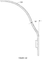
- the radius of curvature of the band 120 (at rest) is 78mm, and the band 120 has an approximate lateral elastic constant of 1N/cm (when force is applied and measured at a central region of one of the ear pad modules).
- an overmolded flex cable that functions as a structural link 150 has an approximate lateral elastic constant of 3N/cm when force is applied and measured at the tip of the flex cable, extended out 5cm.
- the overmolded flex cable has a length of 53mm between an end of the bridge 130 and a corresponding one of the set of earpad modules 110 when the earpad module is fully extended.
- the bridge 130 can have three bridge segments separated from each other by hinged regions, wherein the bridge 130 has an arc length 50-90mm and a radius of curvature from 60-100mm.
- the additional bend angle at two bridge segments can be from 5-15°, and the bridge 130 can have anapproximate lateral elastic constant from 5-20N/cm (when force is applied and measured at a tip region of the bridge).
- the radius of curvature of the band 120 (at rest) is can be from 65-95mm, and the band 120 can have an approximate lateral elastic constant from 0.2-5 N/cm (when force is applied and measured at a central region of one of the ear pad modules).
- the angular ball-and-socket range of motion of an ear pad module 110 in the roll direction can be from +/- 5° to +/- 15°
- the angular ball-and-socket range of motion in the yaw direction can be from +/- 5° to +/-15°.
- the band 120' and the bridge can be directly coupled to each other (e.g., at midregions of the band 120 and the bridge), and/or can be directly coupled to each other at lateral regions byway of elastically deformable and resilient lateral members 160' situated between the band 120' and the bridge 130'.
- the lateral members 160' can comprise materials and/or morphologies that result in a desired spring constant, such that outward deflection of lateral portions of the band 120' produces a desired level of outward deflection of lateral portions of the bridge 130' that couple to the set of lateral electrodes 140'.
Landscapes
- Health & Medical Sciences (AREA)
- Life Sciences & Earth Sciences (AREA)
- Engineering & Computer Science (AREA)
- Biomedical Technology (AREA)
- Animal Behavior & Ethology (AREA)
- General Health & Medical Sciences (AREA)
- Public Health (AREA)
- Veterinary Medicine (AREA)
- Nuclear Medicine, Radiotherapy & Molecular Imaging (AREA)
- Radiology & Medical Imaging (AREA)
- Heart & Thoracic Surgery (AREA)
- Biophysics (AREA)
- Pathology (AREA)
- Physics & Mathematics (AREA)
- Medical Informatics (AREA)
- Molecular Biology (AREA)
- Surgery (AREA)
- Child & Adolescent Psychology (AREA)
- Developmental Disabilities (AREA)
- Hospice & Palliative Care (AREA)
- Neurology (AREA)
- Psychiatry (AREA)
- Psychology (AREA)
- Social Psychology (AREA)
- Electrotherapy Devices (AREA)
Claims (14)
- System zum transkraniellen Stimulieren eines Benutzers, das in einer Kopfregion des Benutzers betrieben werden kann, das System umfassend:• ein Paar von Polstereinheiten, die während einer Verwendung des Systems an gegenüberliegenden Kopfbereichen des Benutzers konfiguriert sind, wobei jede der Polstereinheiten ein starres Außengehäuse umfasst;• ein Band, das ein erstes Ende, das mit einem ersten Polster des Paars von Polstereinheiten verbunden ist, und ein zweites Ende, das mit einem zweiten Polster des Paares von Polstereinheiten verbunden ist, aufweist, wobei ein Abschnitt des Bands mit einer ersten Region des starren Außengehäuses verbunden ist;• eine Brücke, die während einer Verwendung des Systems mit einer Elektrode gekoppelt ist; und• ein Paar von Gliedern, das mit dem Paar von Polstereinheiten gepaart ist, wobei jedes Glied des Gliederpaars mit der Brücke gekoppelt ist, wobei ein Abschnitt eines Glieds des Gliederpaars mit einer zweiten Region des starren Außengehäuses im Inneren der ersten Region gekoppelt ist und einen Elastizitätsmodul über einem Schwellenwertmodul aufweist, sodass:o in einem ersten Betriebsmodus eine seitliche Verschiebung des Paars von Polstereinheiten eine seitliche Verschiebung der Elektrode weg von der Kopfregion des Benutzers bewirkt, undo in einem zweiten Betriebsmodus ein Loslassen des Paars von Polstereinheiten Vorsprünge der Elektrode ungefähr senkrecht zu der Kopfregion des Benutzers ausrichtet.
- System nach Anspruch 1, wobei jede des Paars von Polstereinheiten einen nachgiebigen Abschnitt umfasst, der konfiguriert ist, um während eines Betriebs in Umfangsrichtung positioniert zu werden, und wobei der nachgiebige Abschnitt ein akustisch transparentes Material umfasst.
- System nach Anspruch 1, wobei die Brücke mit einer unteren Mittelregion des Bands verbunden ist und wobei: das Gliederpaar in einer ersten Region mit einem inneren Abschnitt seiner entsprechenden Polstereinheit und in einer zweiten Region mit der Brücke gekoppelt ist.
- System nach Anspruch 1, wobei die Brücke durch das Gliederpaar mit dem Band verbunden ist, wobei das Gliederpaar ein elastisch verformbares Element umfasst, das zwischen der Brücke und dem Band an seitlichen Regionen der Brücke und des Bands konfiguriert ist.
- System nach Anspruch 1, wobei die Brücke einen Gelenksatz umfasst und während eines Betriebs einen Elektrodensatz trägt, der die Elektrode beinhaltet, wobei jedes Gelenk des Gelenksatzes zwischen zwei benachbarten Elektrodenpositionen positioniert ist, die dem Elektrodensatz entsprechen.
- System nach Anspruch 1, wobei die Elektroden eine Anordnung von Vorsprüngen aufweisen, die eine Anordnung von durchlässigen Körpern tragen, die von der Brücke weg ausgerichtet sind, die die elektrische Kopplung zwischen dem System und der Kopfregion des Benutzers während einer Verwendung ermöglichen.
- System nach Anspruch 1, wobei während eines Betriebs eine relative Verschiebung zwischen dem Paar von Polstereinheiten und dem Band eine freiliegende Länge von jedem der Glieder moduliert wird.
- System nach Anspruch 1, wobei jedes der Glieder eine flexible gedruckte Schaltung innerhalb einer isolierenden Hülle umfasst.
- System nach Anspruch 1, ferner umfassend eine zweite Elektrodeneinheit, die mittels eines Kabels mit mindestens einem von der Brücke, dem Band und einer Polstereinheit der Polstereinheiten gekoppelt ist, wobei die zweite Elektrodeneinheit konfiguriert ist, um eine Stimulation von mindestens einer von einer Frontalkortex-Region und Präfrontalkortex-Region des Benutzers während eines Betriebs zu ermöglichen.
- System nach Anspruch 1, wobei die Brücke einen Satz von Aussparungen umfasst, die konfiguriert sind, um einen Elektrodensatz aufzunehmen, der die Elektrode beinhaltet, und wobei jede des Satzes von Aussparungen eine elektromechanische Verbindung zu einem elektronischen System bereitstellt, das eine Bereitstellung einer transkraniellen Stimulation für den Benutzer ermöglicht.
- System nach Anspruch 10, wobei der Satz von Aussparungen ein Paar seitlicher Elektroden und eine mittlere Elektrode trägt, die in der Mitte zwischen dem Paar seitlicher Elektroden positioniert ist, und wobei das System konfiguriert ist, um während eines Betriebs mittels des Elektrodensatzes mindestens eine motorische Kortexregion und/oder eine prämotorische Kortexregion des Benutzers transkraniell zu stimulieren.
- System nach Anspruch 1, wobei jede des Paars von Polstereinheiten einen medial ausgerichteten, nachgiebigen Abschnitt mit einem akustisch transparenten Material umfasst.
- System nach Anspruch 1, ferner umfassend mindestens eines von einem Positionssensor und einem Kraftsensor, der mit mindestens einem von der Brücke, dem Band und dem Paar von Polstereinheiten gekoppelt ist und mindestens eines von dem ersten Betriebsmodus und dem zweiten Betriebsmodus erfasst.
- System nach einem der vorherigen Ansprüche, wobei das Paar von Polstereinheiten ein Paar von Ohrpolstermodulen umfasst, wobei das Paar von Ohrpolstermodulen während einer Verwendung des Systems ein Paar von Verankerungspunkten an kontralateralen Kopfregionen des Benutzers bereitstellt.
Applications Claiming Priority (3)
| Application Number | Priority Date | Filing Date | Title |
|---|---|---|---|
| US201562236200P | 2015-10-26 | 2015-10-26 | |
| US201662289709P | 2016-02-01 | 2016-02-01 | |
| PCT/US2016/058919 WO2017075086A1 (en) | 2015-10-26 | 2016-10-26 | Electrode positioning system and method |
Publications (3)
| Publication Number | Publication Date |
|---|---|
| EP3368146A1 EP3368146A1 (de) | 2018-09-05 |
| EP3368146A4 EP3368146A4 (de) | 2019-06-19 |
| EP3368146B1 true EP3368146B1 (de) | 2021-04-07 |
Family
ID=58564803
Family Applications (1)
| Application Number | Title | Priority Date | Filing Date |
|---|---|---|---|
| EP16860711.7A Active EP3368146B1 (de) | 2015-10-26 | 2016-10-26 | Elektrodenpositionierungssystem |
Country Status (4)
| Country | Link |
|---|---|
| US (2) | US10315026B2 (de) |
| EP (1) | EP3368146B1 (de) |
| CN (1) | CN108290037B (de) |
| WO (1) | WO2017075086A1 (de) |
Families Citing this family (14)
| Publication number | Priority date | Publication date | Assignee | Title |
|---|---|---|---|---|
| US12201427B2 (en) | 2012-06-14 | 2025-01-21 | Medibotics Llc | Headband with brain activity sensors |
| US20230346284A1 (en) * | 2012-06-14 | 2023-11-02 | Medibotics Llc | Dry Electrode with Sliding Electroconductive Protrusions for Use on a Hair-Covered Area of a Person's Head |
| EP3413966A4 (de) | 2016-02-08 | 2019-11-27 | Halo Neuro, Inc. | Verfahren und system zur verbesserung der bereitstellung von elektrischer stimulation |
| USD1061473S1 (en) * | 2017-04-05 | 2025-02-11 | Sonusmed Incorporated | Headset |
| KR102152084B1 (ko) * | 2018-01-18 | 2020-09-04 | 고려대학교 산학협력단 | 신경 자극기 |
| EP3603737B1 (de) | 2018-07-31 | 2020-08-26 | Flow Neuroscience AB | Positionierung von elektroden zur transkranialen stimulation des gehirns |
| WO2020146802A1 (en) * | 2019-01-10 | 2020-07-16 | Jeffrey Bennett | Anatomical/physiological event apparatus and method of treating an approaching |
| WO2020227664A1 (en) * | 2019-05-09 | 2020-11-12 | Rpw Technology, Llc | Systems and methods for a transcranial electrical stimulation device |
| USD908664S1 (en) * | 2019-06-02 | 2021-01-26 | Sens.Ai Inc. | Headset with biometric sensors |
| USD1051088S1 (en) * | 2021-02-25 | 2024-11-12 | Vital Neuro, Inc. | Audio headset |
| CN116784840B (zh) * | 2021-06-07 | 2026-04-17 | 丹阳慧创医疗设备有限公司 | 头部光学施加装置及经颅光调控设备 |
| US11700474B2 (en) | 2021-06-24 | 2023-07-11 | New Audio LLC | Multi-microphone headset |
| USD1000416S1 (en) * | 2021-06-24 | 2023-10-03 | New Audio LLC | Wireless headphones |
| JP7152818B1 (ja) | 2022-01-21 | 2022-10-13 | 東和株式会社 | 生体用電極装置 |
Family Cites Families (117)
| Publication number | Priority date | Publication date | Assignee | Title |
|---|---|---|---|---|
| US3472233A (en) | 1966-12-02 | 1969-10-14 | Robert I Sarbacher | Electrical muscle stimulator |
| US4967038A (en) | 1986-12-16 | 1990-10-30 | Sam Techology Inc. | Dry electrode brain wave recording system |
| CS275292B2 (en) | 1989-02-22 | 1992-02-19 | Cvut Fakulta Elektrotechnick | Private rehabilitation apparatus with ion transcutaneous acceleration |
| US4977895A (en) | 1989-05-22 | 1990-12-18 | Ely Shavit Pasternak | Electrical apparatus for medical treatment |
| US5087242A (en) | 1989-07-21 | 1992-02-11 | Iomed, Inc. | Hydratable bioelectrode |
| US4928696A (en) | 1989-07-26 | 1990-05-29 | Mindcenter Corporation | Electrode-supporting headset |
| EP0429842B1 (de) | 1989-10-27 | 1996-08-28 | Korea Research Institute Of Chemical Technology | Vorrichtung zur transdermalen Applikation von Protein- oder Peptid-Medikamenten |
| US5137817A (en) | 1990-10-05 | 1992-08-11 | Amoco Corporation | Apparatus and method for electroporation |
| US5387231A (en) | 1992-07-21 | 1995-02-07 | Sporer; Patsy | Electrotherapy method |
| US5622168A (en) | 1992-11-18 | 1997-04-22 | John L. Essmyer | Conductive hydrogels and physiological electrodes and electrode assemblies therefrom |
| US20020169485A1 (en) | 1995-10-16 | 2002-11-14 | Neuropace, Inc. | Differential neurostimulation therapy driven by physiological context |
| US6480743B1 (en) | 2000-04-05 | 2002-11-12 | Neuropace, Inc. | System and method for adaptive brain stimulation |
| US7184826B2 (en) | 1996-06-18 | 2007-02-27 | Alza Corporation | Device and method for enhancing transdermal flux of agents being delivered or sampled |
| JPH10234713A (ja) * | 1997-02-28 | 1998-09-08 | Rion Co Ltd | 聴覚検査用骨導受話装置 |
| US6754361B1 (en) * | 1997-04-17 | 2004-06-22 | 3M Innovative Properties Company | Ergonomic headset assembly |
| US6038464A (en) | 1998-02-09 | 2000-03-14 | Axelgaard Manufacturing Co., Ltd. | Medical electrode |
| US6077237A (en) | 1998-11-06 | 2000-06-20 | Adaboy, Inc. | Headset for vestibular stimulation in virtual environments |
| US6379324B1 (en) | 1999-06-09 | 2002-04-30 | The Procter & Gamble Company | Intracutaneous microneedle array apparatus |
| US6510333B1 (en) | 2000-05-16 | 2003-01-21 | Mark J. Licata | Sensor for biopotential measurements |
| US7024247B2 (en) | 2001-10-15 | 2006-04-04 | Northstar Neuroscience, Inc. | Systems and methods for reducing the likelihood of inducing collateral neural activity during neural stimulation threshold test procedures |
| US6505079B1 (en) | 2000-09-13 | 2003-01-07 | Foster Bio Technology Corp. | Electrical stimulation of tissue for therapeutic and diagnostic purposes |
| WO2002087410A2 (en) | 2001-04-27 | 2002-11-07 | Yacov Naisberg | Diagnosis, treatment and research of mental disorders |
| US7643874B2 (en) | 2001-10-24 | 2010-01-05 | Power Paper Ltd. | Dermal patch |
| US7110820B2 (en) | 2002-02-05 | 2006-09-19 | Tcheng Thomas K | Responsive electrical stimulation for movement disorders |
| US20060229502A1 (en) | 2003-06-03 | 2006-10-12 | Bayer Healthcare Llc | Portable medical diagnostic apparatus |
| US20050165460A1 (en) | 2004-01-26 | 2005-07-28 | Onje' Erfan | Neuro-Electric-Therapy Headset |
| EP1750799A2 (de) | 2004-05-04 | 2007-02-14 | The Cleveland Clinic Foundation | Verfahren zur behandlung medizinischer zustände mittels neuromodulation des sympathischen nervensystems |
| US20080027345A1 (en) | 2004-06-25 | 2008-01-31 | Olympus Corporation | Electrode Apparatus For Detecting Brain Waves And Package |
| US7818515B1 (en) | 2004-08-10 | 2010-10-19 | Symantec Operating Corporation | System and method for enforcing device grouping rules for storage virtualization |
| DE102004048864A1 (de) | 2004-10-07 | 2006-04-13 | Roche Diagnostics Gmbh | Analytisches Testelement mit drahtloser Datenübertragung |
| DE102005003735B4 (de) | 2005-01-26 | 2008-04-03 | Cerbomed Gmbh | Vorrichtung zur transkutanen Stimulation eines Nervs des menschlichen Körpers |
| KR100634546B1 (ko) | 2005-06-30 | 2006-10-13 | 삼성전자주식회사 | 생체신호 측정용 전극 |
| US7551952B2 (en) | 2005-10-26 | 2009-06-23 | Sam Technology, Inc. | EEG electrode headset |
| US8874227B2 (en) | 2009-03-20 | 2014-10-28 | ElectroCore, LLC | Devices and methods for non-invasive capacitive electrical stimulation and their use for vagus nerve stimulation on the neck of a patient |
| US7894905B2 (en) | 2006-03-13 | 2011-02-22 | Neuropace, Inc. | Implantable system enabling responsive therapy for pain |
| TW200740410A (en) | 2006-03-22 | 2007-11-01 | Emotiv Systems Pty Ltd | Electrode and electrode headset |
| US20070237797A1 (en) | 2006-03-28 | 2007-10-11 | Gholam A. Peyman | Neural Conduit Agent Dissemination |
| US8116875B2 (en) | 2006-06-16 | 2012-02-14 | Neuropoint Medical, Inc. | Implantable neurostimulation systems |
| DE102006033623B4 (de) | 2006-07-18 | 2010-04-08 | Cerbomed Gmbh | System zur transkutanen Stimulation eines Nervs des menschlichen Körpers |
| EP2116274B1 (de) | 2006-10-13 | 2012-07-11 | Apnex Medical, Inc. | Vorrichtung zur Behandlung von obstruktiver Schlaf-Apnea |
| EP2081644B1 (de) | 2006-10-31 | 2012-05-30 | St. Jude Medical AB | Gewebestimulationsvorrichtung |
| WO2008091876A1 (en) | 2007-01-22 | 2008-07-31 | Novavision, Inc. | Device for treating human vision using combined optical and electrical stimulation |
| KR101002885B1 (ko) | 2007-04-03 | 2010-12-21 | 연세대학교 산학협력단 | 통신 시스템에서 주파수 자원의 할당 장치 및 방법 |
| US8979837B2 (en) | 2007-04-04 | 2015-03-17 | St. Jude Medical, Atrial Fibrillation Division, Inc. | Flexible tip catheter with extended fluid lumen |
| CA2941187C (en) | 2007-08-14 | 2021-03-02 | Fred Hutchinson Cancer Research Center | Needle array assembly and method for delivering therapeutic agents |
| US9757554B2 (en) | 2007-08-23 | 2017-09-12 | Bioness Inc. | System for transmitting electrical current to a bodily tissue |
| US8301265B2 (en) | 2007-09-10 | 2012-10-30 | Medtronic, Inc. | Selective depth electrode deployment for electrical stimulation |
| US8116841B2 (en) | 2007-09-14 | 2012-02-14 | Corventis, Inc. | Adherent device with multiple physiological sensors |
| WO2009042170A1 (en) | 2007-09-26 | 2009-04-02 | Medtronic, Inc. | Therapy program selection |
| EP2211986B1 (de) | 2007-10-16 | 2013-11-20 | Medtronic, Inc. | Therapiesteuerung basierend auf patientenbewegungszustand |
| US20090187159A1 (en) | 2008-01-17 | 2009-07-23 | California Institute Of Technology | Chronically implantable hybrid cannula-microelectrode system for continuous monitoring electrophysiological signals during infusion of a chemical or pharmaceutical agent |
| WO2009134763A1 (en) | 2008-04-29 | 2009-11-05 | Board of Governors for Higher Education, State of Rhode Island and the Providence Plantations | Biomedical sensors usable on un-prepared contact surfaces |
| CN102083495A (zh) * | 2008-06-20 | 2011-06-01 | 麦哲利夫有限公司 | 用于提供非经颅电疗的系统、装置和方法 |
| JP4469024B2 (ja) | 2008-08-26 | 2010-05-26 | パナソニック株式会社 | 人工脂質膜形成方法および人工脂質膜形成装置 |
| DE102008043973B4 (de) | 2008-11-21 | 2011-12-01 | Burkhard Brocke | Vorrichtung zur transkraniellen Neurostimulation |
| AU2008365106B2 (en) * | 2008-12-11 | 2015-02-05 | Bio-Medical Research Limited | Facial stimulation apparatus |
| JP5579984B2 (ja) | 2008-12-25 | 2014-08-27 | 楽天株式会社 | 提示情報登録装置 |
| US9440063B2 (en) | 2008-12-30 | 2016-09-13 | Research Foundation Od The City University Of New York | Methods for reducing discomfort during electrostimulation, and compositions and apparatus therefor |
| US20100268287A1 (en) | 2009-03-13 | 2010-10-21 | The Johns Hopkins University | Methods and devices for increasing learning and effects of training in healthy individuals and patients after brain lesions using dc stimulation and apparatuses and systems related thereto |
| US8989863B2 (en) | 2009-03-23 | 2015-03-24 | Flint Hills Scientific, Llc | System and apparatus for increasing regularity and/or phase-locking of neuronal activity relating to an epileptic event |
| JP5667173B2 (ja) * | 2009-05-18 | 2015-02-12 | コーニンクレッカ フィリップス エヌ ヴェ | 磁性粒子に影響を及ぼし且つ磁性粒子を検出する装置及びその作動方法 |
| JP5589593B2 (ja) | 2009-06-29 | 2014-09-17 | ソニー株式会社 | 生体信号測定用装具 |
| WO2011055291A1 (en) * | 2009-11-04 | 2011-05-12 | Koninklijke Philips Electronics N.V. | Device for positioning electrodes on a user's scalp |
| AU2010315132A1 (en) | 2009-11-04 | 2012-05-31 | Arizona Board Of Regents For And On Behalf Of Arizona State University | Devices and methods for modulating brain activity |
| US9770204B2 (en) | 2009-11-11 | 2017-09-26 | Medtronic, Inc. | Deep brain stimulation for sleep and movement disorders |
| US8373238B2 (en) | 2009-12-03 | 2013-02-12 | Taiwan Semiconductor Manufacturing Company, Ltd. | FinFETs with multiple Fin heights |
| US8838247B2 (en) | 2010-01-06 | 2014-09-16 | Evoke Neuroscience, Inc. | Transcranial stimulation device and method based on electrophysiological testing |
| US8938301B2 (en) * | 2010-01-06 | 2015-01-20 | Evoke Neuroscience, Inc. | Headgear with displaceable sensors for electrophysiology measurement and training |
| US8239030B1 (en) | 2010-01-06 | 2012-08-07 | DJ Technologies | Transcranial stimulation device and method based on electrophysiological testing |
| US20160017558A1 (en) | 2010-04-23 | 2016-01-21 | French Development Enterprises, LLC | Aquatic Animal Passage With Counter |
| US8583237B2 (en) | 2010-09-13 | 2013-11-12 | Cranial Medical Systems, Inc. | Devices and methods for tissue modulation and monitoring |
| US8473063B2 (en) | 2010-09-22 | 2013-06-25 | Medtronic, Inc. | Method and apparatus for event-triggered reinforcement of a favorable brain state |
| US20120184894A1 (en) | 2010-12-31 | 2012-07-19 | Mir Imran | Patches and Methods for the Transdermal Delivery of Agents to Treat Hair Loss |
| US8706181B2 (en) | 2011-01-25 | 2014-04-22 | Medtronic, Inc. | Target therapy delivery site selection |
| DE102011078696A1 (de) | 2011-07-05 | 2013-01-10 | Smp Swiss Macro Polymers Ag | Anordnung aus Gewebehülse und Aushärtmaterial zum Befestigen eines Verankerungselements in einem Bohrloch |
| US20130204315A1 (en) | 2011-08-05 | 2013-08-08 | Ndi Medical, Llc | Systems for and methods of transcranial direct current electrical stimulation |
| US9061148B2 (en) | 2011-09-22 | 2015-06-23 | Djo, Llc | Devices, systems and methods for treating pain with electrical stimulation |
| KR101826912B1 (ko) | 2011-11-07 | 2018-02-08 | 인텔렉츄얼 키스톤 테크놀로지 엘엘씨 | 광전변환소자 및 그 제조 방법 |
| US8818515B2 (en) | 2012-01-13 | 2014-08-26 | Research Foundation Of The City University Of New York | Voltage limited neurostimulation |
| WO2013113059A1 (en) | 2012-01-31 | 2013-08-08 | Creativity Cap | A method and device for increasing human ability for idea generation and insight related tasks using dc stimulation |
| US20130261706A1 (en) | 2012-03-30 | 2013-10-03 | Neuropace, Inc. | Systems and methods for applying rapid sequential electrode stimulation |
| US9080918B2 (en) | 2012-09-11 | 2015-07-14 | Syntouch Llc | Compliant tactile sensor with fluid-filled, sponge-like material |
| US10814131B2 (en) | 2012-11-26 | 2020-10-27 | Thync Global, Inc. | Apparatuses and methods for neuromodulation |
| US9440070B2 (en) | 2012-11-26 | 2016-09-13 | Thyne Global, Inc. | Wearable transdermal electrical stimulation devices and methods of using them |
| CN204147427U (zh) | 2012-11-26 | 2015-02-11 | 塞恩克公司 | 可穿戴的皮肤电刺激设备 |
| US8874220B2 (en) | 2012-12-13 | 2014-10-28 | Nuraleve Inc. | Neurostimulation system, device, and method |
| WO2014117208A1 (en) | 2013-01-29 | 2014-08-07 | National Ict Australia Limited | Neuroprosthetic stimulation |
| US8880173B2 (en) | 2013-03-12 | 2014-11-04 | Ethicon Endo-Surgery, Inc. | Device for providing transdermal electrical stimulation at an adjustable position on a head |
| CA2942750C (en) | 2013-03-15 | 2022-06-28 | Neurolief Ltd. | Headset for treatment and assessment of medical conditions |
| US9913973B2 (en) | 2013-04-23 | 2018-03-13 | Yani Skincare, LLC | Transcranial direct current brain stimulation apparatus |
| WO2014176450A1 (en) | 2013-04-24 | 2014-10-30 | Neurosigma, Inc. | Modulation of autonomic nervous system activity and integrated electrode assemblies for trigeminal neurostimulation |
| ES2696707T3 (es) | 2013-06-29 | 2019-01-17 | Cerevast Medical Inc | Dispositivos de estimulación eléctrica transcutánea y métodos para modificar o inducir el estado cognitivo |
| US9782585B2 (en) | 2013-08-27 | 2017-10-10 | Halo Neuro, Inc. | Method and system for providing electrical stimulation to a user |
| US9486618B2 (en) | 2013-08-27 | 2016-11-08 | Halo Neuro, Inc. | Electrode system for electrical stimulation |
| CN107157479A (zh) * | 2013-08-27 | 2017-09-15 | 哈洛纽罗公司 | 用于电刺激的电极系统 |
| EP3038700B1 (de) * | 2013-08-27 | 2020-03-11 | Halo Neuro, Inc. | Verfahren und system zur bereitstellung einer elektrischer stimulation an einen benutzer |
| US10076279B2 (en) * | 2013-10-22 | 2018-09-18 | Neba Health, Llc | System and method for a compact EEG headset |
| US10188342B2 (en) | 2013-11-05 | 2019-01-29 | The University Of North Carolina At Chapel Hill | Methods, apparatuses and systems for transcranial stimulation |
| US9186505B2 (en) | 2014-02-21 | 2015-11-17 | Novo HB, LLC | Transcranial electrostimulation device and method |
| CN106573138A (zh) | 2014-02-27 | 2017-04-19 | 赛威医疗公司 | 用于神经刺激的用户控制的方法和装置 |
| TWM488322U (zh) * | 2014-03-14 | 2014-10-21 | Contour Optik Inc | 跨顱電刺激裝置 |
| CN204017145U (zh) * | 2014-04-25 | 2014-12-17 | 上海银狐医疗科技有限公司 | 一种头戴式刺激电极 |
| WO2015179281A2 (en) | 2014-05-17 | 2015-11-26 | Thync, Inc. | Methods and apparatuses for the application of ensemble waveforms using transdermal neurostimulation |
| US20150335877A1 (en) | 2014-05-25 | 2015-11-26 | Douglas Jeffery | Cantilever electrodes for transdermal and transcranial stimulation |
| US10322282B2 (en) | 2014-06-06 | 2019-06-18 | Medtronic, Inc. | External stimulation therapy for dorsal genital nerve stimulation |
| JP2016010482A (ja) * | 2014-06-27 | 2016-01-21 | パナソニックIpマネジメント株式会社 | 光育毛装置 |
| KR101525450B1 (ko) | 2014-08-01 | 2015-06-03 | (주)와이브레인 | 전기 자극 장치 |
| CN204411500U (zh) * | 2014-12-23 | 2015-06-24 | 先進電子醫療工業有限公司 | 头戴式无线控制经颅电刺激仪 |
| EP3244965B8 (de) | 2015-01-13 | 2023-05-17 | Theranica Bio-Electronics Ltd. | Behandlung von kopfschmerzen durch elektrische stimulation |
| TWI581771B (zh) | 2015-04-14 | 2017-05-11 | 財團法人紡織產業綜合研究所 | 傷口護理用敷材 |
| EP3302682A1 (de) | 2015-05-29 | 2018-04-11 | Cerevast Medical Inc. | Verfahren und vorrichtung zur transdermalen elektrischen stimulation |
| US9686602B2 (en) * | 2015-06-15 | 2017-06-20 | Uneo Inc. | Green headphone |
| US10143397B2 (en) * | 2015-06-15 | 2018-12-04 | Edward Lafe Altshuler | Electrode holding device |
| KR20150088224A (ko) | 2015-07-13 | 2015-07-31 | 안범주 | 교통 신호 제어 시스템 |
| KR20170021158A (ko) | 2015-08-17 | 2017-02-27 | 엘지전자 주식회사 | 지문 인식을 수행하는 이동 단말기 및 그 제어방법 |
| KR20170028197A (ko) | 2015-09-03 | 2017-03-13 | 옥윤선 | IoT 기반의 지퍼를 이용한 모니터링 시스템, 이를 이용한 모니터링 방법 |
| KR20180021565A (ko) | 2016-08-22 | 2018-03-05 | 엘지전자 주식회사 | 제상 장치 및 이를 구비하는 냉장고 |
-
2016
- 2016-10-26 EP EP16860711.7A patent/EP3368146B1/de active Active
- 2016-10-26 US US15/335,240 patent/US10315026B2/en active Active
- 2016-10-26 CN CN201680068575.4A patent/CN108290037B/zh active Active
- 2016-10-26 WO PCT/US2016/058919 patent/WO2017075086A1/en not_active Ceased
-
2019
- 2019-04-29 US US16/397,917 patent/US11273304B2/en active Active
Non-Patent Citations (1)
| Title |
|---|
| None * |
Also Published As
| Publication number | Publication date |
|---|---|
| US20170113033A1 (en) | 2017-04-27 |
| EP3368146A1 (de) | 2018-09-05 |
| US20190255313A1 (en) | 2019-08-22 |
| CN108290037A (zh) | 2018-07-17 |
| WO2017075086A1 (en) | 2017-05-04 |
| US10315026B2 (en) | 2019-06-11 |
| EP3368146A4 (de) | 2019-06-19 |
| US11273304B2 (en) | 2022-03-15 |
| CN108290037B (zh) | 2021-10-08 |
Similar Documents
| Publication | Publication Date | Title |
|---|---|---|
| US11273304B2 (en) | Electrode positioning system and method | |
| Park et al. | Soft sensors and actuators for wearable human–machine interfaces | |
| US20250031780A1 (en) | Apparatus, system, and method for reducing head or neck trauma | |
| US20240207605A1 (en) | Neural sleeve for neuromuscular stimulation, sensing and recording | |
| US11071672B2 (en) | Method and apparatus for improving human balance and gait and preventing foot injury | |
| US10383550B2 (en) | Monitoring body movement or condition according to motion regimen with conformal electronics | |
| US10390755B2 (en) | Monitoring body movement or condition according to motion regimen with conformal electronics | |
| KR102390107B1 (ko) | 국부 신경 자극 | |
| Ortner et al. | An SSVEP BCI to control a hand orthosis for persons with tetraplegia | |
| ES2906777T3 (es) | Manguito neural para estimulación, detección y registro neuromuscular | |
| US20210393946A1 (en) | System for electrical stimulation | |
| EP3060113B1 (de) | Neuroprothetisches system zur wiederherstellung der funktion der oberen gliedmassen durch koordinierte elektrostimulation | |
| EP3558114A2 (de) | Überwachung von körperbewegungen oder zuständen in abhängigkeit eines bewegungsschemas mit konformer elektronik | |
| TW201825045A (zh) | 利用表皮電子裝置監測和治療疼痛 | |
| KR20150095675A (ko) | 적응형 외골격, 이를 제어하기 위한 장치 및 방법 | |
| KR20190031979A (ko) | 방향성 자극을 인가하는 웨어러블 타입의 근육 자극 장치 및 그것의 제어 방법 | |
| JP2018015435A (ja) | 筋電気刺激装置、筋電気刺激システム、筋電気刺激方法およびプログラム | |
| CN111918693B (zh) | 非侵入性神经刺激 | |
| US20190091472A1 (en) | Non-invasive eye-tracking control of neuromuscular stimulation system | |
| WO2021220127A1 (en) | Multi-dimensional sensory feedback system | |
| Vinil et al. | Investigation of controllable multi electrode based FES (functional electrical stimulation) system for restoration of grasp-preliminary study on healthy individuals | |
| Lam | Vibrotactile pattern recognition on the torso with one and two dimensional displays | |
| Nakamura | A torso haptic display based on shape memory alloy actuators | |
| HK40014289A (en) | Monitoring body movement or condition according to motion regimen with conformal electronics |
Legal Events
| Date | Code | Title | Description |
|---|---|---|---|
| STAA | Information on the status of an ep patent application or granted ep patent |
Free format text: STATUS: THE INTERNATIONAL PUBLICATION HAS BEEN MADE |
|
| PUAI | Public reference made under article 153(3) epc to a published international application that has entered the european phase |
Free format text: ORIGINAL CODE: 0009012 |
|
| STAA | Information on the status of an ep patent application or granted ep patent |
Free format text: STATUS: REQUEST FOR EXAMINATION WAS MADE |
|
| 17P | Request for examination filed |
Effective date: 20180509 |
|
| AK | Designated contracting states |
Kind code of ref document: A1 Designated state(s): AL AT BE BG CH CY CZ DE DK EE ES FI FR GB GR HR HU IE IS IT LI LT LU LV MC MK MT NL NO PL PT RO RS SE SI SK SM TR |
|
| AX | Request for extension of the european patent |
Extension state: BA ME |
|
| DAV | Request for validation of the european patent (deleted) | ||
| DAX | Request for extension of the european patent (deleted) | ||
| A4 | Supplementary search report drawn up and despatched |
Effective date: 20190520 |
|
| RIC1 | Information provided on ipc code assigned before grant |
Ipc: A61N 1/04 20060101AFI20190514BHEP Ipc: A61N 1/36 20060101ALI20190514BHEP Ipc: H04R 5/033 20060101ALN20190514BHEP Ipc: A61B 5/00 20060101ALN20190514BHEP Ipc: H04R 1/10 20060101ALN20190514BHEP |
|
| GRAP | Despatch of communication of intention to grant a patent |
Free format text: ORIGINAL CODE: EPIDOSNIGR1 |
|
| STAA | Information on the status of an ep patent application or granted ep patent |
Free format text: STATUS: GRANT OF PATENT IS INTENDED |
|
| RIC1 | Information provided on ipc code assigned before grant |
Ipc: A61N 1/04 20060101AFI20200221BHEP Ipc: A61B 5/00 20060101ALN20200221BHEP Ipc: H04R 5/033 20060101ALN20200221BHEP Ipc: A61N 1/36 20060101ALI20200221BHEP Ipc: H04R 1/10 20060101ALN20200221BHEP |
|
| INTG | Intention to grant announced |
Effective date: 20200326 |
|
| GRAS | Grant fee paid |
Free format text: ORIGINAL CODE: EPIDOSNIGR3 |
|
| GRAA | (expected) grant |
Free format text: ORIGINAL CODE: 0009210 |
|
| STAA | Information on the status of an ep patent application or granted ep patent |
Free format text: STATUS: THE PATENT HAS BEEN GRANTED |
|
| AK | Designated contracting states |
Kind code of ref document: B1 Designated state(s): AL AT BE BG CH CY CZ DE DK EE ES FI FR GB GR HR HU IE IS IT LI LT LU LV MC MK MT NL NO PL PT RO RS SE SI SK SM TR |
|
| REG | Reference to a national code |
Ref country code: GB Ref legal event code: FG4D |
|
| REG | Reference to a national code |
Ref country code: AT Ref legal event code: REF Ref document number: 1378894 Country of ref document: AT Kind code of ref document: T Effective date: 20210415 Ref country code: CH Ref legal event code: EP |
|
| REG | Reference to a national code |
Ref country code: DE Ref legal event code: R096 Ref document number: 602016055844 Country of ref document: DE |
|
| REG | Reference to a national code |
Ref country code: IE Ref legal event code: FG4D |
|
| REG | Reference to a national code |
Ref country code: LT Ref legal event code: MG9D |
|
| REG | Reference to a national code |
Ref country code: NL Ref legal event code: MP Effective date: 20210407 Ref country code: AT Ref legal event code: MK05 Ref document number: 1378894 Country of ref document: AT Kind code of ref document: T Effective date: 20210407 |
|
| PG25 | Lapsed in a contracting state [announced via postgrant information from national office to epo] |
Ref country code: LT Free format text: LAPSE BECAUSE OF FAILURE TO SUBMIT A TRANSLATION OF THE DESCRIPTION OR TO PAY THE FEE WITHIN THE PRESCRIBED TIME-LIMIT Effective date: 20210407 Ref country code: FI Free format text: LAPSE BECAUSE OF FAILURE TO SUBMIT A TRANSLATION OF THE DESCRIPTION OR TO PAY THE FEE WITHIN THE PRESCRIBED TIME-LIMIT Effective date: 20210407 Ref country code: NL Free format text: LAPSE BECAUSE OF FAILURE TO SUBMIT A TRANSLATION OF THE DESCRIPTION OR TO PAY THE FEE WITHIN THE PRESCRIBED TIME-LIMIT Effective date: 20210407 Ref country code: HR Free format text: LAPSE BECAUSE OF FAILURE TO SUBMIT A TRANSLATION OF THE DESCRIPTION OR TO PAY THE FEE WITHIN THE PRESCRIBED TIME-LIMIT Effective date: 20210407 Ref country code: AT Free format text: LAPSE BECAUSE OF FAILURE TO SUBMIT A TRANSLATION OF THE DESCRIPTION OR TO PAY THE FEE WITHIN THE PRESCRIBED TIME-LIMIT Effective date: 20210407 Ref country code: BG Free format text: LAPSE BECAUSE OF FAILURE TO SUBMIT A TRANSLATION OF THE DESCRIPTION OR TO PAY THE FEE WITHIN THE PRESCRIBED TIME-LIMIT Effective date: 20210707 |
|
| PG25 | Lapsed in a contracting state [announced via postgrant information from national office to epo] |
Ref country code: RS Free format text: LAPSE BECAUSE OF FAILURE TO SUBMIT A TRANSLATION OF THE DESCRIPTION OR TO PAY THE FEE WITHIN THE PRESCRIBED TIME-LIMIT Effective date: 20210407 Ref country code: SE Free format text: LAPSE BECAUSE OF FAILURE TO SUBMIT A TRANSLATION OF THE DESCRIPTION OR TO PAY THE FEE WITHIN THE PRESCRIBED TIME-LIMIT Effective date: 20210407 Ref country code: NO Free format text: LAPSE BECAUSE OF FAILURE TO SUBMIT A TRANSLATION OF THE DESCRIPTION OR TO PAY THE FEE WITHIN THE PRESCRIBED TIME-LIMIT Effective date: 20210707 Ref country code: PT Free format text: LAPSE BECAUSE OF FAILURE TO SUBMIT A TRANSLATION OF THE DESCRIPTION OR TO PAY THE FEE WITHIN THE PRESCRIBED TIME-LIMIT Effective date: 20210809 Ref country code: PL Free format text: LAPSE BECAUSE OF FAILURE TO SUBMIT A TRANSLATION OF THE DESCRIPTION OR TO PAY THE FEE WITHIN THE PRESCRIBED TIME-LIMIT Effective date: 20210407 Ref country code: GR Free format text: LAPSE BECAUSE OF FAILURE TO SUBMIT A TRANSLATION OF THE DESCRIPTION OR TO PAY THE FEE WITHIN THE PRESCRIBED TIME-LIMIT Effective date: 20210708 Ref country code: IS Free format text: LAPSE BECAUSE OF FAILURE TO SUBMIT A TRANSLATION OF THE DESCRIPTION OR TO PAY THE FEE WITHIN THE PRESCRIBED TIME-LIMIT Effective date: 20210807 Ref country code: LV Free format text: LAPSE BECAUSE OF FAILURE TO SUBMIT A TRANSLATION OF THE DESCRIPTION OR TO PAY THE FEE WITHIN THE PRESCRIBED TIME-LIMIT Effective date: 20210407 |
|
| REG | Reference to a national code |
Ref country code: DE Ref legal event code: R097 Ref document number: 602016055844 Country of ref document: DE |
|
| PG25 | Lapsed in a contracting state [announced via postgrant information from national office to epo] |
Ref country code: ES Free format text: LAPSE BECAUSE OF FAILURE TO SUBMIT A TRANSLATION OF THE DESCRIPTION OR TO PAY THE FEE WITHIN THE PRESCRIBED TIME-LIMIT Effective date: 20210407 Ref country code: RO Free format text: LAPSE BECAUSE OF FAILURE TO SUBMIT A TRANSLATION OF THE DESCRIPTION OR TO PAY THE FEE WITHIN THE PRESCRIBED TIME-LIMIT Effective date: 20210407 Ref country code: EE Free format text: LAPSE BECAUSE OF FAILURE TO SUBMIT A TRANSLATION OF THE DESCRIPTION OR TO PAY THE FEE WITHIN THE PRESCRIBED TIME-LIMIT Effective date: 20210407 Ref country code: CZ Free format text: LAPSE BECAUSE OF FAILURE TO SUBMIT A TRANSLATION OF THE DESCRIPTION OR TO PAY THE FEE WITHIN THE PRESCRIBED TIME-LIMIT Effective date: 20210407 Ref country code: DK Free format text: LAPSE BECAUSE OF FAILURE TO SUBMIT A TRANSLATION OF THE DESCRIPTION OR TO PAY THE FEE WITHIN THE PRESCRIBED TIME-LIMIT Effective date: 20210407 Ref country code: SM Free format text: LAPSE BECAUSE OF FAILURE TO SUBMIT A TRANSLATION OF THE DESCRIPTION OR TO PAY THE FEE WITHIN THE PRESCRIBED TIME-LIMIT Effective date: 20210407 Ref country code: SK Free format text: LAPSE BECAUSE OF FAILURE TO SUBMIT A TRANSLATION OF THE DESCRIPTION OR TO PAY THE FEE WITHIN THE PRESCRIBED TIME-LIMIT Effective date: 20210407 |
|
| PLBE | No opposition filed within time limit |
Free format text: ORIGINAL CODE: 0009261 |
|
| STAA | Information on the status of an ep patent application or granted ep patent |
Free format text: STATUS: NO OPPOSITION FILED WITHIN TIME LIMIT |
|
| 26N | No opposition filed |
Effective date: 20220110 |
|
| REG | Reference to a national code |
Ref country code: CH Ref legal event code: PL |
|
| PG25 | Lapsed in a contracting state [announced via postgrant information from national office to epo] |
Ref country code: IS Free format text: LAPSE BECAUSE OF FAILURE TO SUBMIT A TRANSLATION OF THE DESCRIPTION OR TO PAY THE FEE WITHIN THE PRESCRIBED TIME-LIMIT Effective date: 20210807 Ref country code: AL Free format text: LAPSE BECAUSE OF FAILURE TO SUBMIT A TRANSLATION OF THE DESCRIPTION OR TO PAY THE FEE WITHIN THE PRESCRIBED TIME-LIMIT Effective date: 20210407 |
|
| REG | Reference to a national code |
Ref country code: BE Ref legal event code: MM Effective date: 20211031 |
|
| PG25 | Lapsed in a contracting state [announced via postgrant information from national office to epo] |
Ref country code: MC Free format text: LAPSE BECAUSE OF FAILURE TO SUBMIT A TRANSLATION OF THE DESCRIPTION OR TO PAY THE FEE WITHIN THE PRESCRIBED TIME-LIMIT Effective date: 20210407 |
|
| PG25 | Lapsed in a contracting state [announced via postgrant information from national office to epo] |
Ref country code: LU Free format text: LAPSE BECAUSE OF NON-PAYMENT OF DUE FEES Effective date: 20211026 Ref country code: IT Free format text: LAPSE BECAUSE OF FAILURE TO SUBMIT A TRANSLATION OF THE DESCRIPTION OR TO PAY THE FEE WITHIN THE PRESCRIBED TIME-LIMIT Effective date: 20210407 Ref country code: BE Free format text: LAPSE BECAUSE OF NON-PAYMENT OF DUE FEES Effective date: 20211031 |
|
| PG25 | Lapsed in a contracting state [announced via postgrant information from national office to epo] |
Ref country code: LI Free format text: LAPSE BECAUSE OF NON-PAYMENT OF DUE FEES Effective date: 20211031 Ref country code: CH Free format text: LAPSE BECAUSE OF NON-PAYMENT OF DUE FEES Effective date: 20211031 |
|
| PG25 | Lapsed in a contracting state [announced via postgrant information from national office to epo] |
Ref country code: IE Free format text: LAPSE BECAUSE OF NON-PAYMENT OF DUE FEES Effective date: 20211026 |
|
| PG25 | Lapsed in a contracting state [announced via postgrant information from national office to epo] |
Ref country code: HU Free format text: LAPSE BECAUSE OF FAILURE TO SUBMIT A TRANSLATION OF THE DESCRIPTION OR TO PAY THE FEE WITHIN THE PRESCRIBED TIME-LIMIT; INVALID AB INITIO Effective date: 20161026 |
|
| PG25 | Lapsed in a contracting state [announced via postgrant information from national office to epo] |
Ref country code: CY Free format text: LAPSE BECAUSE OF FAILURE TO SUBMIT A TRANSLATION OF THE DESCRIPTION OR TO PAY THE FEE WITHIN THE PRESCRIBED TIME-LIMIT Effective date: 20210407 |
|
| PG25 | Lapsed in a contracting state [announced via postgrant information from national office to epo] |
Ref country code: MK Free format text: LAPSE BECAUSE OF FAILURE TO SUBMIT A TRANSLATION OF THE DESCRIPTION OR TO PAY THE FEE WITHIN THE PRESCRIBED TIME-LIMIT Effective date: 20210407 |
|
| REG | Reference to a national code |
Ref country code: GB Ref legal event code: 732E Free format text: REGISTERED BETWEEN 20240509 AND 20240515 |
|
| PG25 | Lapsed in a contracting state [announced via postgrant information from national office to epo] |
Ref country code: MT Free format text: LAPSE BECAUSE OF FAILURE TO SUBMIT A TRANSLATION OF THE DESCRIPTION OR TO PAY THE FEE WITHIN THE PRESCRIBED TIME-LIMIT Effective date: 20210407 |
|
| PG25 | Lapsed in a contracting state [announced via postgrant information from national office to epo] |
Ref country code: TR Free format text: LAPSE BECAUSE OF FAILURE TO SUBMIT A TRANSLATION OF THE DESCRIPTION OR TO PAY THE FEE WITHIN THE PRESCRIBED TIME-LIMIT Effective date: 20210407 |
|
| PGFP | Annual fee paid to national office [announced via postgrant information from national office to epo] |
Ref country code: DE Payment date: 20251024 Year of fee payment: 10 |
|
| PGFP | Annual fee paid to national office [announced via postgrant information from national office to epo] |
Ref country code: GB Payment date: 20251003 Year of fee payment: 10 |
|
| PGFP | Annual fee paid to national office [announced via postgrant information from national office to epo] |
Ref country code: FR Payment date: 20251003 Year of fee payment: 10 |