EP3368201B1 - Verfahren zur konfektionierung und auftragung von klebstoffen - Google Patents
Verfahren zur konfektionierung und auftragung von klebstoffen Download PDFInfo
- Publication number
- EP3368201B1 EP3368201B1 EP16809692.3A EP16809692A EP3368201B1 EP 3368201 B1 EP3368201 B1 EP 3368201B1 EP 16809692 A EP16809692 A EP 16809692A EP 3368201 B1 EP3368201 B1 EP 3368201B1
- Authority
- EP
- European Patent Office
- Prior art keywords
- unit
- adhesive
- supply
- color pigment
- hot
- Prior art date
- Legal status (The legal status is an assumption and is not a legal conclusion. Google has not performed a legal analysis and makes no representation as to the accuracy of the status listed.)
- Active
Links
Images




Classifications
-
- B—PERFORMING OPERATIONS; TRANSPORTING
- B01—PHYSICAL OR CHEMICAL PROCESSES OR APPARATUS IN GENERAL
- B01F—MIXING, e.g. DISSOLVING, EMULSIFYING OR DISPERSING
- B01F23/00—Mixing according to the phases to be mixed, e.g. dispersing or emulsifying
- B01F23/40—Mixing liquids with liquids; Emulsifying
- B01F23/47—Mixing liquids with liquids; Emulsifying involving high-viscosity liquids, e.g. asphalt
-
- B—PERFORMING OPERATIONS; TRANSPORTING
- B29—WORKING OF PLASTICS; WORKING OF SUBSTANCES IN A PLASTIC STATE IN GENERAL
- B29B—PREPARATION OR PRETREATMENT OF THE MATERIAL TO BE SHAPED; MAKING GRANULES OR PREFORMS; RECOVERY OF PLASTICS OR OTHER CONSTITUENTS OF WASTE MATERIAL CONTAINING PLASTICS
- B29B7/00—Mixing; Kneading
- B29B7/30—Mixing; Kneading continuous, with mechanical mixing or kneading devices
- B29B7/34—Mixing; Kneading continuous, with mechanical mixing or kneading devices with movable mixing or kneading devices
- B29B7/38—Mixing; Kneading continuous, with mechanical mixing or kneading devices with movable mixing or kneading devices rotary
- B29B7/40—Mixing; Kneading continuous, with mechanical mixing or kneading devices with movable mixing or kneading devices rotary with single shaft
- B29B7/401—Mixing; Kneading continuous, with mechanical mixing or kneading devices with movable mixing or kneading devices rotary with single shaft having a casing closely surrounding the rotor, e.g. with a plunger for feeding the material
-
- B—PERFORMING OPERATIONS; TRANSPORTING
- B01—PHYSICAL OR CHEMICAL PROCESSES OR APPARATUS IN GENERAL
- B01F—MIXING, e.g. DISSOLVING, EMULSIFYING OR DISPERSING
- B01F23/00—Mixing according to the phases to be mixed, e.g. dispersing or emulsifying
- B01F23/40—Mixing liquids with liquids; Emulsifying
- B01F23/405—Methods of mixing liquids with liquids
-
- B—PERFORMING OPERATIONS; TRANSPORTING
- B01—PHYSICAL OR CHEMICAL PROCESSES OR APPARATUS IN GENERAL
- B01F—MIXING, e.g. DISSOLVING, EMULSIFYING OR DISPERSING
- B01F23/00—Mixing according to the phases to be mixed, e.g. dispersing or emulsifying
- B01F23/40—Mixing liquids with liquids; Emulsifying
- B01F23/43—Mixing liquids with liquids; Emulsifying using driven stirrers
-
- B—PERFORMING OPERATIONS; TRANSPORTING
- B01—PHYSICAL OR CHEMICAL PROCESSES OR APPARATUS IN GENERAL
- B01F—MIXING, e.g. DISSOLVING, EMULSIFYING OR DISPERSING
- B01F23/00—Mixing according to the phases to be mixed, e.g. dispersing or emulsifying
- B01F23/40—Mixing liquids with liquids; Emulsifying
- B01F23/45—Mixing liquids with liquids; Emulsifying using flow mixing
-
- B—PERFORMING OPERATIONS; TRANSPORTING
- B01—PHYSICAL OR CHEMICAL PROCESSES OR APPARATUS IN GENERAL
- B01F—MIXING, e.g. DISSOLVING, EMULSIFYING OR DISPERSING
- B01F23/00—Mixing according to the phases to be mixed, e.g. dispersing or emulsifying
- B01F23/50—Mixing liquids with solids
- B01F23/51—Methods thereof
- B01F23/511—Methods thereof characterised by the composition of the liquids or solids
-
- B—PERFORMING OPERATIONS; TRANSPORTING
- B01—PHYSICAL OR CHEMICAL PROCESSES OR APPARATUS IN GENERAL
- B01F—MIXING, e.g. DISSOLVING, EMULSIFYING OR DISPERSING
- B01F23/00—Mixing according to the phases to be mixed, e.g. dispersing or emulsifying
- B01F23/50—Mixing liquids with solids
- B01F23/53—Mixing liquids with solids using driven stirrers
-
- B—PERFORMING OPERATIONS; TRANSPORTING
- B01—PHYSICAL OR CHEMICAL PROCESSES OR APPARATUS IN GENERAL
- B01F—MIXING, e.g. DISSOLVING, EMULSIFYING OR DISPERSING
- B01F23/00—Mixing according to the phases to be mixed, e.g. dispersing or emulsifying
- B01F23/50—Mixing liquids with solids
- B01F23/57—Mixing high-viscosity liquids with solids
-
- B—PERFORMING OPERATIONS; TRANSPORTING
- B01—PHYSICAL OR CHEMICAL PROCESSES OR APPARATUS IN GENERAL
- B01F—MIXING, e.g. DISSOLVING, EMULSIFYING OR DISPERSING
- B01F25/00—Flow mixers; Mixers for falling materials, e.g. solid particles
- B01F25/40—Static mixers
- B01F25/42—Static mixers in which the mixing is affected by moving the components jointly in changing directions, e.g. in tubes provided with baffles or obstructions
- B01F25/43—Mixing tubes, e.g. wherein the material is moved in a radial or partly reversed direction
- B01F25/431—Straight mixing tubes with baffles or obstructions that do not cause substantial pressure drop; Baffles therefor
- B01F25/4314—Straight mixing tubes with baffles or obstructions that do not cause substantial pressure drop; Baffles therefor with helical baffles
- B01F25/43141—Straight mixing tubes with baffles or obstructions that do not cause substantial pressure drop; Baffles therefor with helical baffles composed of consecutive sections of helical formed elements
-
- B—PERFORMING OPERATIONS; TRANSPORTING
- B01—PHYSICAL OR CHEMICAL PROCESSES OR APPARATUS IN GENERAL
- B01F—MIXING, e.g. DISSOLVING, EMULSIFYING OR DISPERSING
- B01F27/00—Mixers with rotary stirring devices in fixed receptacles; Kneaders
- B01F27/05—Stirrers
- B01F27/11—Stirrers characterised by the configuration of the stirrers
- B01F27/114—Helically shaped stirrers, i.e. stirrers comprising a helically shaped band or helically shaped band sections
-
- B—PERFORMING OPERATIONS; TRANSPORTING
- B01—PHYSICAL OR CHEMICAL PROCESSES OR APPARATUS IN GENERAL
- B01F—MIXING, e.g. DISSOLVING, EMULSIFYING OR DISPERSING
- B01F27/00—Mixers with rotary stirring devices in fixed receptacles; Kneaders
- B01F27/50—Pipe mixers, i.e. mixers wherein the materials to be mixed flow continuously through pipes, e.g. column mixers
-
- B—PERFORMING OPERATIONS; TRANSPORTING
- B01—PHYSICAL OR CHEMICAL PROCESSES OR APPARATUS IN GENERAL
- B01F—MIXING, e.g. DISSOLVING, EMULSIFYING OR DISPERSING
- B01F27/00—Mixers with rotary stirring devices in fixed receptacles; Kneaders
- B01F27/55—Mixers with rotary stirring devices in fixed receptacles; Kneaders with stirrers driven by the moving material
-
- B—PERFORMING OPERATIONS; TRANSPORTING
- B05—SPRAYING OR ATOMISING IN GENERAL; APPLYING FLUENT MATERIALS TO SURFACES, IN GENERAL
- B05D—PROCESSES FOR APPLYING FLUENT MATERIALS TO SURFACES, IN GENERAL
- B05D1/00—Processes for applying liquids or other fluent materials
- B05D1/26—Processes for applying liquids or other fluent materials performed by applying the liquid or other fluent material from an outlet device in contact with, or almost in contact with, the surface
-
- B—PERFORMING OPERATIONS; TRANSPORTING
- B05—SPRAYING OR ATOMISING IN GENERAL; APPLYING FLUENT MATERIALS TO SURFACES, IN GENERAL
- B05D—PROCESSES FOR APPLYING FLUENT MATERIALS TO SURFACES, IN GENERAL
- B05D1/00—Processes for applying liquids or other fluent materials
- B05D1/28—Processes for applying liquids or other fluent materials performed by transfer from the surfaces of elements carrying the liquid or other fluent material, e.g. brushes, pads, rollers
-
- B—PERFORMING OPERATIONS; TRANSPORTING
- B05—SPRAYING OR ATOMISING IN GENERAL; APPLYING FLUENT MATERIALS TO SURFACES, IN GENERAL
- B05D—PROCESSES FOR APPLYING FLUENT MATERIALS TO SURFACES, IN GENERAL
- B05D5/00—Processes for applying liquids or other fluent materials to surfaces to obtain special surface effects, finishes or structures
- B05D5/10—Processes for applying liquids or other fluent materials to surfaces to obtain special surface effects, finishes or structures to obtain an adhesive surface
-
- B—PERFORMING OPERATIONS; TRANSPORTING
- B29—WORKING OF PLASTICS; WORKING OF SUBSTANCES IN A PLASTIC STATE IN GENERAL
- B29B—PREPARATION OR PRETREATMENT OF THE MATERIAL TO BE SHAPED; MAKING GRANULES OR PREFORMS; RECOVERY OF PLASTICS OR OTHER CONSTITUENTS OF WASTE MATERIAL CONTAINING PLASTICS
- B29B7/00—Mixing; Kneading
- B29B7/30—Mixing; Kneading continuous, with mechanical mixing or kneading devices
- B29B7/32—Mixing; Kneading continuous, with mechanical mixing or kneading devices with non-movable mixing or kneading devices
- B29B7/325—Static mixers
-
- B—PERFORMING OPERATIONS; TRANSPORTING
- B29—WORKING OF PLASTICS; WORKING OF SUBSTANCES IN A PLASTIC STATE IN GENERAL
- B29B—PREPARATION OR PRETREATMENT OF THE MATERIAL TO BE SHAPED; MAKING GRANULES OR PREFORMS; RECOVERY OF PLASTICS OR OTHER CONSTITUENTS OF WASTE MATERIAL CONTAINING PLASTICS
- B29B7/00—Mixing; Kneading
- B29B7/30—Mixing; Kneading continuous, with mechanical mixing or kneading devices
- B29B7/34—Mixing; Kneading continuous, with mechanical mixing or kneading devices with movable mixing or kneading devices
- B29B7/38—Mixing; Kneading continuous, with mechanical mixing or kneading devices with movable mixing or kneading devices rotary
- B29B7/40—Mixing; Kneading continuous, with mechanical mixing or kneading devices with movable mixing or kneading devices rotary with single shaft
-
- B—PERFORMING OPERATIONS; TRANSPORTING
- B29—WORKING OF PLASTICS; WORKING OF SUBSTANCES IN A PLASTIC STATE IN GENERAL
- B29B—PREPARATION OR PRETREATMENT OF THE MATERIAL TO BE SHAPED; MAKING GRANULES OR PREFORMS; RECOVERY OF PLASTICS OR OTHER CONSTITUENTS OF WASTE MATERIAL CONTAINING PLASTICS
- B29B7/00—Mixing; Kneading
- B29B7/30—Mixing; Kneading continuous, with mechanical mixing or kneading devices
- B29B7/58—Component parts, details or accessories; Auxiliary operations
- B29B7/60—Component parts, details or accessories; Auxiliary operations for feeding, e.g. end guides for the incoming material
- B29B7/603—Component parts, details or accessories; Auxiliary operations for feeding, e.g. end guides for the incoming material in measured doses, e.g. proportioning of several materials
-
- B—PERFORMING OPERATIONS; TRANSPORTING
- B29—WORKING OF PLASTICS; WORKING OF SUBSTANCES IN A PLASTIC STATE IN GENERAL
- B29B—PREPARATION OR PRETREATMENT OF THE MATERIAL TO BE SHAPED; MAKING GRANULES OR PREFORMS; RECOVERY OF PLASTICS OR OTHER CONSTITUENTS OF WASTE MATERIAL CONTAINING PLASTICS
- B29B7/00—Mixing; Kneading
- B29B7/80—Component parts, details or accessories; Auxiliary operations
- B29B7/88—Adding charges, i.e. additives
- B29B7/94—Liquid charges
-
- C—CHEMISTRY; METALLURGY
- C09—DYES; PAINTS; POLISHES; NATURAL RESINS; ADHESIVES; COMPOSITIONS NOT OTHERWISE PROVIDED FOR; APPLICATIONS OF MATERIALS NOT OTHERWISE PROVIDED FOR
- C09J—ADHESIVES; NON-MECHANICAL ASPECTS OF ADHESIVE PROCESSES IN GENERAL; ADHESIVE PROCESSES NOT PROVIDED FOR ELSEWHERE; USE OF MATERIALS AS ADHESIVES
- C09J175/00—Adhesives based on polyureas or polyurethanes; Adhesives based on derivatives of such polymers
- C09J175/04—Polyurethanes
-
- B—PERFORMING OPERATIONS; TRANSPORTING
- B01—PHYSICAL OR CHEMICAL PROCESSES OR APPARATUS IN GENERAL
- B01F—MIXING, e.g. DISSOLVING, EMULSIFYING OR DISPERSING
- B01F2101/00—Mixing characterised by the nature of the mixed materials or by the application field
- B01F2101/2305—Mixers of the two-component package type, i.e. where at least two components are separately stored, and are mixed in the moment of application
-
- B—PERFORMING OPERATIONS; TRANSPORTING
- B01—PHYSICAL OR CHEMICAL PROCESSES OR APPARATUS IN GENERAL
- B01F—MIXING, e.g. DISSOLVING, EMULSIFYING OR DISPERSING
- B01F2101/00—Mixing characterised by the nature of the mixed materials or by the application field
- B01F2101/36—Mixing of ingredients for adhesives or glues; Mixing adhesives and gas
-
- B—PERFORMING OPERATIONS; TRANSPORTING
- B01—PHYSICAL OR CHEMICAL PROCESSES OR APPARATUS IN GENERAL
- B01F—MIXING, e.g. DISSOLVING, EMULSIFYING OR DISPERSING
- B01F25/00—Flow mixers; Mixers for falling materials, e.g. solid particles
- B01F25/40—Static mixers
- B01F25/42—Static mixers in which the mixing is affected by moving the components jointly in changing directions, e.g. in tubes provided with baffles or obstructions
- B01F25/43—Mixing tubes, e.g. wherein the material is moved in a radial or partly reversed direction
- B01F25/431—Straight mixing tubes with baffles or obstructions that do not cause substantial pressure drop; Baffles therefor
- B01F25/43197—Straight mixing tubes with baffles or obstructions that do not cause substantial pressure drop; Baffles therefor characterised by the mounting of the baffles or obstructions
- B01F25/431972—Mounted on an axial support member, e.g. a rod or bar
-
- B—PERFORMING OPERATIONS; TRANSPORTING
- B05—SPRAYING OR ATOMISING IN GENERAL; APPLYING FLUENT MATERIALS TO SURFACES, IN GENERAL
- B05C—APPARATUS FOR APPLYING FLUENT MATERIALS TO SURFACES, IN GENERAL
- B05C1/00—Apparatus in which liquid or other fluent material is applied to the surface of the work by contact with a member carrying the liquid or other fluent material, e.g. a porous member loaded with a liquid to be applied as a coating
- B05C1/04—Apparatus in which liquid or other fluent material is applied to the surface of the work by contact with a member carrying the liquid or other fluent material, e.g. a porous member loaded with a liquid to be applied as a coating for applying liquid or other fluent material to work of indefinite length
- B05C1/08—Apparatus in which liquid or other fluent material is applied to the surface of the work by contact with a member carrying the liquid or other fluent material, e.g. a porous member loaded with a liquid to be applied as a coating for applying liquid or other fluent material to work of indefinite length using a roller or other rotating member which contacts the work along a generating line
-
- B—PERFORMING OPERATIONS; TRANSPORTING
- B05—SPRAYING OR ATOMISING IN GENERAL; APPLYING FLUENT MATERIALS TO SURFACES, IN GENERAL
- B05C—APPARATUS FOR APPLYING FLUENT MATERIALS TO SURFACES, IN GENERAL
- B05C11/00—Component parts, details or accessories not specifically provided for in groups B05C1/00 - B05C9/00
- B05C11/10—Storage, supply or control of liquid or other fluent material; Recovery of excess liquid or other fluent material
- B05C11/1042—Storage, supply or control of liquid or other fluent material; Recovery of excess liquid or other fluent material provided with means for heating or cooling the liquid or other fluent material in the supplying means upstream of the applying apparatus
-
- B—PERFORMING OPERATIONS; TRANSPORTING
- B29—WORKING OF PLASTICS; WORKING OF SUBSTANCES IN A PLASTIC STATE IN GENERAL
- B29B—PREPARATION OR PRETREATMENT OF THE MATERIAL TO BE SHAPED; MAKING GRANULES OR PREFORMS; RECOVERY OF PLASTICS OR OTHER CONSTITUENTS OF WASTE MATERIAL CONTAINING PLASTICS
- B29B7/00—Mixing; Kneading
- B29B7/30—Mixing; Kneading continuous, with mechanical mixing or kneading devices
- B29B7/58—Component parts, details or accessories; Auxiliary operations
- B29B7/72—Measuring, controlling or regulating
Definitions
- the invention relates to continuous processes for the formulation and application of adhesives, characterized in that (i) a base component of the adhesive is continuously mixed with at least one additive to produce a formulated adhesive; and (ii) the adhesive thus formulated is applied to a substrate.
- a standardized adhesive is usually used in the manufacture of furniture or furniture elements, which is used in all applications and for all furniture elements. Due to its color, the adhesive is barely visible in some color combinations, while in other color combinations of the furniture or furniture element, the adhesive is visually disadvantageous because its color does not match the color of the furniture or furniture element.
- the use of an appropriately colored adhesive often fails due to the amount of adhesive that an adhesive manufacturer has to purchase, which can only be purchased profitably if very large quantities are to be processed.
- the EP 1 743 777 A1 discloses an adhesive application station that allows colorants to be added to the adhesive.
- the disclosed adhesive application station has the disadvantage that the quantities of adhesive that can be produced with it can only be produced in discontinuous operation.
- the mixing takes place after the colorant has been added to the adhesive, whereby after the adhesive has been mixed, the mixing unit is removed and the adhesive is pressed out of an outlet slot by moving the piston provided in the housing of the station. After the adhesive produced in this way has been used up, new adhesive must be added to the station, the mixing unit reinserted and a new batch of adhesive produced and mixed.
- This station is therefore not suitable for continuous operation on an industrial scale for the production of large quantities of furniture or furniture elements.
- At least one refers to 1 or more, for example 1, 2, 3, 4, 5, 6, 7, 8, 9 or more. In the context of components of the compositions described herein, this indication does not refer to the absolute amount of molecules, but to the type of component. "At least one polyol” therefore means, for example, one or more different polyols, i.e. one or more different types of polyols. Together with quantity indications, the quantity indications refer to the total amount of the correspondingly designated type of component, as already defined above.
- Continuous as used herein in connection with the described processes means that the processes are operated continuously, i.e. that the mixing and application are carried out continuously, in particular that the application is carried out directly after the mixing/confectioning in a continuous process.
- the method can also comprise a further step (iii), namely the bonding of the substrate to a second substrate in order to obtain a workpiece.
- This second substrate can be an edge band that is bonded to a chipboard (the first substrate).
- the application of the adhesive to the substrate can generally be carried out over part of the surface, i.e. limited to certain areas of the substrate. In the preferred embodiments of the invention, the application takes place on the narrow side of a (chipboard), whereby the adhesive can also be applied to the narrow side over the entire surface or only over part of the surface, whereby in the latter case the complete wetting of the narrow side surface can take place by pressing when bonding with an edge band.
- the bonded substrates obtained in this way, i.e. in particular chipboard and edge bands produced by the methods according to the invention are also referred to herein as "workpieces".
- the basic component of the adhesive and/or the at least one additive are added in a controlled manner in step (i). This enables the adhesive to be adapted to the desired purpose or to the substrate used via the type and amount of additive, in particular with regard to color, curing speed, adhesive strength, etc.
- the basic component of the adhesive is a hot melt adhesive composition.
- “Basic component” as used herein means that it is the actual binder.
- the basic component is already a complete adhesive composition that can be used directly as such and can, for example, already be commercially available in this form.
- the additive can only bring about a further adaptation of the adhesive composition to the desired application, for example a color adaptation.
- the additive can also contain components that influence the adhesive properties. Corresponding additives are described in detail below.
- the base component of the adhesive is a hot melt adhesive composition that is solid at room temperature and liquid at elevated temperature.
- "Liquid” as used herein refers to compositions that are flowable at the specified temperature and normal pressure (1013 mbar).
- the hot melt adhesive compositions have melting temperatures in the range from 90 to 300°C, in particular in the range from 120 to 250°C, with the melting temperature also depending on the adhesive system used.
- 1-component reactive adhesive systems can be used. These can, for example, be moisture-curing. Such reactive adhesives can, for example, be polyurethane-based. Suitable adhesives are available under the trade name Technomelt PUR (Henkel AG & Co. KGaA, DE). Alternatively, other types of crosslinking can also be used. The use of 2K adhesives, which are then mixed together directly before or in step (i), is also possible. Alternatively, the adhesive base components used can be non-reactive hot melt adhesives, ie in particular physically curing, thermoplastic adhesive systems. Such systems are also known in the prior art and are based in particular on polyolefins.
- hot melt adhesives are preferably used, the methods are carried out in various embodiments in such a way that the assembly and/or application of the adhesive takes place at an elevated temperature, in particular at a temperature above the melting point of the basic component of the adhesive.
- the corresponding temperature ranges are the ranges already disclosed above in connection with hot melt adhesives.
- temperatures in the range of 100 to 140°C are usually used, and for non-reactive thermoplastic adhesive systems, temperatures in the range of 150 to 220°C are often used. In general, however, the temperatures are selected depending on the adhesive used and the substrate. The temperatures are selected so that the adhesive is in a form suitable for assembly and application, but at the same time decomposition of the adhesive, adverse effects on the substrate and unnecessary energy consumption are minimized.
- the at least one additive comprises in particular a substance which influences the chemical properties, the biological properties and/or the physical properties of the adhesive.
- Chemical properties include, but are not limited to, adhesion and/or cure speed, for example.
- Biological properties include, but are not limited to, biocidal properties and mold resistance, while physical properties include, for example, viscosity, recrystallization behavior, and color.
- the at least one additive comprises at least one color pigment; in various embodiments, the at least one additive comprises an agent for improving moisture resistance or resistance to mold formation, a biocidal agent, an additive for improved energy absorption, a primer for improved bonding, an agent for influencing the recrystallization of the adhesive and/or a reaction accelerator, particularly preferably a color pigment and/or an agent for influencing the recrystallization of the adhesive.
- active components of the additive can be formulated with a carrier that is compatible with the adhesive system.
- this carrier can include one or more polyols.
- the carrier can also be one or more polyolefins.
- the active ingredient of the additive often a color pigment or a mixture of color pigments, is then mixed into this carrier.
- the at least one additive is therefore liquid at room temperature and comprises at least one polyol that is liquid at room temperature, at least one color pigment and optionally at least one reaction accelerator.
- the at least one additive is solid at room temperature and comprises at least one polyolefin solid at room temperature and at least one color pigment.
- the additive is used in various embodiments to adapt the colour of the adhesive to the workpiece, for example to adapt the colour of an adhesive joint to a wood or chipboard as well as the edge band used, which is glued to the narrow side of the board.
- additives that influence the recrystallization behavior of the adhesive can positively change the reworkability in the so-called post-processing zones of the devices used, for example edge banding machines, in such a way that smearing in these zones is avoided.
- the at least one additive is selected to comprise at least one agent for influencing the recrystallization of the adhesive, which is added in step (i) in such a way that the reworkability of the workpiece produced from the substrate to which the adhesive is applied in step (ii) is improved.
- Reaction accelerators can accelerate the cross-linking of reactive adhesives so that further processing can be carried out more quickly. These can therefore also be selected and added in a controlled manner in step (i) so that the cross-linking of the adhesive is accelerated after step (ii).
- the additives are mixed into the basic component of the adhesive in amounts that are adapted to the intended use. Such adaptation can also be carried out continuously, for example depending on the type and/or color of the substrate.
- the amounts added are usually in the range of 0.01 to 20 wt.% based on the total weight of the formulated adhesive, preferably in the range of 0.01 to 10 wt.%, more preferably 0.1 to 5 wt.%. Such amounts enable simple and controlled dosing without adversely affecting the properties of the adhesive.
- the additive can be added to the reactive adhesives described herein in the form of an appropriate formulation, for example in amounts of 0 to 2 wt.%, preferably 0.1 to 2 wt.%, based on the total weight of the formulated adhesive.
- the additive can be added to the non-reactive adhesives described herein in the form of a corresponding formulation, for example in amounts of 0 to 5 wt.%, preferably 0.1 to 5 wt.%, based on the total weight of the finished adhesive.
- the at least one additive comprising at least one color pigment is selected and added in a controlled manner in step (i) such that the color of the adhesive thus prepared is adapted as desired, for example adapted to the substrate to which it is applied in step (ii).
- the substrate can be, for example, a wood or chipboard, with the adhesive being used to glue edge bands onto the narrow side and thus finish it to obtain a finished workpiece.
- the edge bands can be made of plastics, such as ABS, PP or similar, as well as paper-based materials.
- One embodiment of the invention relates to a method in which a device for preparing and applying adhesive is provided, the device comprising a feed unit, a preparation unit and an application unit, the feed unit serving to feed a base component of the adhesive and/or the at least one additive, the preparation unit causing a continuous mixing of the base component of the adhesive with the supplied additives to form the prepared adhesive and a continuous conveying of the prepared adhesive, and the adhesive thus prepared is conveyed from the preparation unit into the application unit and can be applied to a substrate by the application unit.
- the adhesive can thus be provided with selectable additives and mixed starting from a base component, so that the adhesive produced in this way can be applied to the substrate.
- the color can be selected with additives and the chemical properties and/or biological properties and/or physical properties of the adhesive can also be influenced.
- Biocidal properties can be influenced to reduce the formation of mold or water resistance can be improved.
- Electrical properties can also be influenced in a targeted manner.
- the feed unit has a dosing unit for the dosed supply of the base component and/or at least one additive.
- the base component and the selected additive or additives can be dosed in the required quantities.
- only the base component can be dosed and the additives can be fed manually in a simplified version.
- the packaging unit has a dosing unit for the dosed supply of at least one additive.
- the feed unit allows manual feeding of the base component and/or at least one additive or has such a feed.
- the feed unit allows a controlled feed of the base component and/or at least one additive or has such a feed.
- an automated controlled feed can thus take place by means of the feed unit, so that a corresponding mixing and application can then take place.
- the packaging unit allows a controlled supply of the base component and/or at least one additive or has such a supply. In this way, in addition to the supply of the feed unit, subsequent dosing can also be carried out.
- the feed unit and/or the packaging unit comprises at least one pump, which ensures a continuous feed or conveyance of the base component.
- a separate pump can be provided for the base component, which can also be used to convey the mixed adhesive.
- a pump can also be provided for conveying the mixed adhesive.
- a pump is provided for at least one additive or for several additives or for each additive.
- the pump can be designed, for example, as a gear pump or as an injector or similar.
- the feed unit and/or the packaging unit comprises a pump which causes a continuous or discrete feed of at least one additive.
- the additive can be dosed to achieve the desired mixture.
- the feed unit and/or the assembly unit has a heater for melting the base component and/or at least one additive.
- the adhesive can then be processed as a hot melt adhesive.
- the packaging unit has a mixing device for mixing the base component and/or the at least one additive. This achieves good homogenization of the adhesive as a mixture of the base component and the additives used.
- the packaging unit has a mixing device with a mixing chamber for mixing the base component and/or the at least one additive.
- the packaging unit has a static or dynamic mixing agent in the mixing chamber. This improves the mixing of the adhesive and allows it to be carried out in a shorter time.
- the dynamic mixing agent is a driven, particularly rotating, mixing agent. This allows particularly effective mixing to be carried out.
- the static mixing agent is a fixed mixing agent in the mixing chamber and/or on a wall of the mixing chamber. This makes it possible to find a particularly cost-effective solution.
- the static mixing medium is formed by a hollow cylindrical chamber with a spiral-shaped flow path within it. This ensures good mixing over the length of the flow path.
- the spiral-shaped flow path is formed by a spiral helix inserted into the hollow cylindrical chamber. This makes it particularly easy to form the mixing agent. If the helix can be removed, it can also be easily cleaned.
- the static mixing medium is formed by a spiral helix arranged or formed on the wall of the mixing chamber. This can protrude from the wall or be incorporated into the wall as a kind of groove. This creates a spiral flow that causes mixing.
- the packaging unit has a distribution device for the distributed introduction of the base component and/or for the distributed introduction of at least one additive into the mixing chamber. This already creates a good basis for good mixing because the base component and/or the at least one additive is/are already distributed in the mixing chamber before mixing.
- the mixing chamber has an outlet opening for discharging the mixed adhesive into the application unit. This allows the mixed adhesive to be continuously discharged from the packaging unit in order to fill the application unit and ideally to achieve a continuous application process.
- the application unit has means for applying the adhesive. This allows the adhesive to be applied specifically to the substrate to be processed.
- the means for applying the adhesive has a nozzle and/or an application roller. This allows the adhesive to be applied in a targeted and metered manner.
- the application unit has a reservoir for temporarily storing a defined amount of adhesive. This ensures that a certain amount of adhesive is available that can be applied while, for example, the packaging unit is being filled or the additives are being changed.
- the reservoir serves as a feed unit and packaging unit.
- the mixing in the reservoir takes place due to the rotation of the application roller.
- the application roller thus creates a flow in the adhesive quantity in the reservoir, which contributes to improved mixing.
- the Figure 1 shows a first embodiment of a device 1 for the preparation and application of adhesive, with a feed unit 2, a preparation unit 3 and an application unit 4, which can be used in the method according to the invention.
- the feed unit 2 serves to feed the basic component of the adhesive, whereby the basic component of the adhesive can already be provided in liquid or fluid form.
- the basic component of the adhesive can also be provided as a solid, granulate or powder or similar and filled into the feed unit 2.
- the feed unit 2 can have a melting unit 5, which serves to melt the basic component.
- the feed unit 2 feeds the basic component to the assembly unit 3, which in turn can be fed with additives.
- the base component and the additive(s) are then mixed in the finishing unit 3.
- a non-driven rotating mixer, a driven rotating mixer or a static, non-rotating mixer can be used in the A packaging unit 3 can be provided, which mixes the components to be mixed in the packaging unit 3.
- the mixed components of the adhesive are then fed from the packaging unit 3 into the application unit 4, from where the adhesive can be applied to a substrate.
- the application unit 4 has a means by which the application to the substrate can be carried out, such as an application roller 6.
- the feed unit 2 can also serve to feed the base component of the adhesive and at least one additive, so that the feed unit 2 already receives the base component and the at least one additive and then forwards them to the assembly unit, for example for mixing the components.
- the supply of the basic component to the supply unit and/or to the assembly unit is preferably carried out in a controlled, automated manner.
- one or the other component can also be supplied manually.
- the packaging unit 3 causes a continuous mixing of the base component of the adhesive with the added additive(s) to form the prepared adhesive and it also causes a continuous conveying of the prepared adhesive.
- the packaging unit preferably has a pump which conveys the base component or the mixed adhesive. If only the base component is conveyed by the pump, the mixed adhesive is also conveyed because the base component makes up the majority of the mixed adhesive.
- the Figure 2 shows a further embodiment of a device 11 according to the invention for the preparation and application of adhesive, with a feed unit 12, a preparation unit 13 and an application unit 14.
- the feed unit 12 is again used to feed the base component 16 of the adhesive, whereby the base component 16 of the adhesive, as already explained above, can already be provided in liquid or fluid form.
- the base component 16 of the adhesive can also be provided as a solid, granulate or powder or similar and filled into the feed unit 12.
- the feed unit 12 can optionally have a melting unit 15, which serves to melt the base component 16.
- the base component 16 is fed from the feed unit 12 to the preparation unit 13, to which additives 17 can optionally also be fed. Alternatively, the additives 17 can also be fed to the feed unit 12, as Figure 2 shows.
- the base component 16 and the additive(s) 17 are then mixed in the packaging unit 13.
- a non-driven rotating mixer, a driven rotating mixer or a static, non-rotating mixer can be provided in the packaging unit 13, which mixes the components 16, 17 to be mixed. in the assembly unit 13.
- the mixed components 16, 17 of the adhesive are then fed from the assembly unit 13 into the application unit 14, by means of which the adhesive can be applied to a substrate.
- the application unit 14 in turn has a means by means of which the application of the adhesive to the substrate is carried out, such as an application roller 18.
- At least one additive is also supplied via the supply unit 12, so that the supply unit 12 already receives the base component 16 and also the at least one additive 17 and then forwards these to the packaging unit 13, for example for mixing the components.
- the supply of the basic component 16 to the supply unit 12 and/or to the assembly unit 13 is preferably carried out in a controlled, automated manner.
- the basic component 16 can also be supplied manually.
- the additives 17 are advantageously supplied manually.
- these additives 17 can also be supplied automatically.
- the packaging unit 13 in turn effects a continuous mixing of the base component 16 of the adhesive with the added additive(s) 17 to form the finished adhesive and it also effects a continuous conveyance of the finished adhesive.
- the packaging unit optionally and preferably has a pump (not shown) which conveys the base component or the mixed adhesive. If only the base component is conveyed by the pump, the mixed adhesive is also conveyed because the base component makes up the majority of the mixed adhesive.
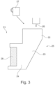
- the Figure 3 shows a further embodiment of the device 21 according to the invention for the preparation and application of adhesive.
- the device includes a feed unit 22, a preparation unit 23 and an application unit 24, all of which are integrated in a housing 25 or in a container.
- the feed unit 22 is again used to feed the base component 26 of the adhesive, whereby the base component 26 of the adhesive, as already explained above, can be provided in liquid or fluid form.
- the base component 26 of the adhesive can also alternatively be provided as a solid, granulate or powder or similar and filled into the feed unit 22.
- the feed unit 22 can optionally have a melting unit, which serves to melt the base component 26, which in Figure 3 However, this is not shown.
- the feed unit 22 supplies the base component 26 and the at least one additive 27 the packaging unit 23.
- the base component 26 and the additive(s) 27 are then mixed in the packaging unit 23.
- a non-driven rotating mixer, a driven rotating mixer or a static, non-rotating mixer can be provided in the packaging unit 23, which mixes the components 26, 27 to be mixed in the packaging unit 23.
- the application roller 28 can also indirectly serve as a mixer, which, due to its rotation in the packaging unit, causes a flow which mixes the base component and the at least one additive.
- the mixed components 26, 27 of the adhesive are then discharged from the application unit 24 and applied to a substrate by means of the application roller 28.
- At least one additive is also supplied via the supply unit 22.
- the supply of the base component 26 to the supply unit 22 is preferably carried out manually, although this can alternatively also be carried out in a controlled manner.
- the additives 27 are advantageously supplied manually. Alternatively, these additives 27 can also be supplied automatically.
- the Figures 4 to 6 show embodiments of packaging units that are designed with different mixers.
- the Figure 4 shows a packaging unit 50 with a housing 51, in which a volume 52 is designed as a mixing chamber.
- a pump 54 is provided, which causes the basic component and/or the additive or additives to be conveyed into the mixing chamber 52 of the housing 51.
- the basic component is introduced into the mixing chamber 52 via a feed 55 with inlets 56 to the mixing chamber, see Figure 5
- the feed 55 distributes the base component in the mixing chamber 52 via the spiral channel guide.
- three channels are formed in the exemplary embodiment, which let the base component into the mixing chamber over an angle of approximately 120°, with the inlets 56 each arranged offset by 120°.
- the pump 54 can preferably be a gear pump.
- the pump 54 serves as a dosing unit for the metered supply of the base component into the mixing chamber 52.
- a dosing unit 57 which effects the addition of at least one additive component.
- the dosing unit 57 can have a reservoir 58 and a valve 59 so that the metering is carried out by controlling the valve 59.
- the pump 54 can be used for this purpose to convey the additive into the mixing chamber 52.
- the metering unit 57 can also have its own pump or injector, by means of which the at least one additive is metered into the mixing chamber 52.
- the housing 51 is advantageously heatable so that a molten base component and/or a molten additive can continue to be processed in a molten state.
- the packaging unit 50 has a mixing device 60 for mixing the base component and/or the at least one additive.
- a rotatable mixing element 61 is arranged in the mixing chamber 52, which can be driven by a drive motor 62 by means of the shaft 63 to mix the base component and/or the at least one additive.
- the mixing element 61 is accordingly a dynamic mixing means that can be rotated in a controlled manner.
- the drive motor 62 is preferably an electric motor or another type of motor. In addition to driving the mixing element 61, the motor 62 can also drive the pump 54. This would eliminate the need for a drive because one drive could be used for two purposes at the same time.
- the drive motor 62 can alternatively or additionally also be provided to drive the pump for conveying the additives.
- the mixing chamber 52 preferably has an opening 65 on its underside 64, by means of which the mixed adhesive can be discharged from the packaging unit 50.
- FIGS. 6 and 7 show a further embodiment of a packaging unit 70 according to the invention, which is essentially similar to the packaging unit 50 of Figures 4 and 5 trained.
- the device 70 is provided with a non-driven mixing element 71, which is rotatably mounted in the mixing chamber 52, but is not designed to be driven by the drive 62.
- the shaft 63 does not drive the mixing element 71.
- the mixing element 71 can, however, rotate due to the flow of the adhesive in the mixing chamber and thus mixes the adhesive consisting of base component and/or at least one additive.
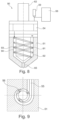
- FIGS 8 and 9 show a further embodiment of a packaging unit 90, which is essentially similar to the packaging unit 50 of Figures 4 and 5 and which can also be used in the inventive method
- the device 90 is designed with a static mixer 91.
- the static mixer 91 consists of a hollow cylinder 92 in which a helix 93 is inserted to form a spiral-shaped flow path 94.
- the fluid base component and the additives flow along the flow path and mix there.
- the mixer 91 is thus a static mixing means which is designed as a fixed mixing means in the mixing chamber or on a wall of the mixing chamber.
- the mixing chamber is modified to form a spiral-shaped flow path which is formed by a hollow cylindrical chamber with a spiral-shaped flow path therein.
- Technomelt PUR 270/7 (Henkel AG & Co. KGaA, DE) was used as the adhesive base component, into which color pastes in yellow, magenta and blue were stirred in amounts of 0.1, 0.5 or 1.0 wt.% based on the total weight of the adhesive. To do this, the adhesive base component was melted in a convection oven for 45 minutes at 140°C. 200g of this was transferred to a reactor (160°C) and the color paste was added and stirred for 10 minutes in a vacuum.
- Technomelt PUR 270/7 (Henkel AG & Co. KGaA, DE) was again used as the adhesive base component, into which a black color paste was stirred in amounts of 1, 2, 3 or 5 wt.% based on the total weight of the adhesive. To do this, the adhesive base component was melted in a convection oven for 45 minutes at 140°C. 200g of this was transferred to a reactor (160°C) and the color paste was added and stirred in a vacuum for 10 minutes.
- An adhesive base component (Technomelt PUR 270/7, Henkel AG & Co. KGaA, DE) was applied with a color paste as described in Examples 1 and 2 using a HOMAG POWERLINE KRF 620 edge banding machine with an application roller (Nordson MC Series) and a melting device (Nordson MC Series) to the straight edge of a chipboard (IKEA 19.00 mm height) and then an ABS edge band (Giplast Sincro, Sitech) with a thickness of 0.9 mm was glued on.
- the conditions were as follows:
Landscapes
- Chemical & Material Sciences (AREA)
- Chemical Kinetics & Catalysis (AREA)
- Engineering & Computer Science (AREA)
- Mechanical Engineering (AREA)
- Dispersion Chemistry (AREA)
- Organic Chemistry (AREA)
- Civil Engineering (AREA)
- Structural Engineering (AREA)
- Adhesives Or Adhesive Processes (AREA)
- Application Of Or Painting With Fluid Materials (AREA)
- Coating Apparatus (AREA)
- Accessories For Mixers (AREA)
- Health & Medical Sciences (AREA)
- Medicinal Chemistry (AREA)
- Polymers & Plastics (AREA)
Description
- Die Erfindung betrifft kontinuierliche Verfahren zur Konfektionierung und Auftragung von Klebstoffen dadurch gekennzeichnet, dass (i) eine Grundkomponente des Klebstoffs mit mindestens einem Zuschlagsstoff kontinuierlich gemischt wird um einen konfektionierten Klebstoff herzustellen; und (ii) der so konfektionierte Klebstoff auf ein Substrat aufgetragen wird.
- Bei der Fertigung von Möbeln oder Möbelelementen werden größerflächige Platten eingesetzt, die auf Maß zugeschnitten werden und die an ihren schmalen Kanten mit einem Kantenband versehen werden. Das Kantenband wird dabei mittels eines Klebstoffs auf die Schmalseite der Platte geklebt. Dabei zeigt sich, dass die Anforderungen an den Klebstoff variieren und je nach Möbelelement und/oder Möbel und/oder Anwendungsfall und/oder Einsatzgebiet unterschiedliche Eigenschaften aufweisen sollte.
- So wird bei der Möbel- oder Möbelelementfertigung üblicher Weise ein standardisierter Klebstoff verwendet, der bei allen Anwendungen und bei allen Möbelelementen eingesetzt wird. Dabei ist der Klebstoff aufgrund seiner Farbe bei manchen Farbkombinationen nur wenig sichtbar, wobei bei anderen Farbkombinationen des Möbels oder des Möbelelements der Klebstoff eher optisch nachteilig auffällt, weil seine Farbe eher nicht zu der Farbe des Möbels oder Möbelelements passt. Der Einsatz eines entsprechend eingefärbten Klebstoffs scheitert oft an den von einem Klebstoffhersteller abzunehmenden Klebstoffmengen, die nur bei sehr hohen zu verarbeitenden Stückzahlen rentabel eingekauft werden können.
- Die
EP 1 743 777 A1 offenbart eine Klebstoffauftragstation, die eine Zumischung von Farbstoffen zu dem Klebstoff erlaubt. Die offenbarte Klebstoffauftragstation hat jedoch den Nachteil, dass die mit ihr erzeugbaren Klebstoffmengen nur in einem diskontinuierlichen Betrieb erzeugt werden können. Die Mischung erfolgt dabei nach Zudosierung des Farbstoffs zu dem Klebstoff, wobei nach der Mischung des Klebstoffs das Mischaggregat entfernt wird und der Klebstoff durch Verlagerung des im Gehäuse der Station vorgesehenen Kolbens aus einem Austrittsschlitz gepresst wird. Nach dem Aufbrauchen des so erzeugten Klebstoffs muss neuer Klebstoff in die Station nachgefüllt, das Mischaggregat wieder eingesetzt und eine neue Charge des Klebstoffs erzeugt und gemischt werden. Diese Station eignet sich daher nicht für einen kontinuierlichen Betrieb im industriellen Maßstab zur Herstellung größerer Stückzahlen von Möbeln oder Möbelelementen. - Auch ist es oft der Wunsch, den Klebstoff an seinen Einsatzzweck hin oder bezüglich des Einsatzzweckes des Möbels gezielt anzupassen.
- Es ist die Aufgabe der Erfindung, eine kontinuierliches Verfahren zur Konfektionierung und Auftragung von Klebstoffen zu schaffen, die eine Individualisierung von Klebstoffen erlaubt und dennoch auch für im Handwerksbereich einsetzbar ist oder auch für industriell bearbeitbare Mengen geeignet ist.
- Diese Aufgabe wird mit den hierin beschriebenen Verfahren gelöst. In einem ersten Aspekt betrifft die Erfindung daher ein kontinuierliches Verfahren zur Konfektionierung und Auftragung einer Klebstoffzusammensetzung zur Verklebung von Spanplatten mit einem Kantenband, dadurch gekennzeichnet, dass
- (i) eine Schmelzklebstoffzusammensetzung umfassend mindestens einen Zuschlagsstoff mit mindestens einem Farbpigment kontinuierlich gemischt wird, um einen konfektionierten Klebstoff herzustellen;
- (ii) der so konfektionierte Klebstoff kontinuierlich auf ein Substrat aufgetragen wird, wobei es sich bei dem Substrat um eine Spanplatte handelt;
- (iii) das Substrat mit einem zweiten Substrat verklebt wird, wobei es sich bei dem zweiten Substrat um ein Kantenband handelt,
- "Mindestens ein", wie hierin verwendet, bezieht sich auf 1 oder mehr, beispielsweise 1, 2, 3, 4, 5, 6, 7, 8, 9 oder mehr. Im Zusammenhang mit Bestandteilen der hierin beschriebenen Zusammensetzungen bezieht sich diese Angabe nicht auf die absolute Menge an Molekülen, sondern auf die Art des Bestandteils. "Mindestens ein Polyol" bedeutet daher beispielsweise ein oder mehrere verschiedene Polyole, d.h. eine oder mehrere verschiedene Arten von Polyolen. Zusammen mit Mengenangaben beziehen sich die Mengenangaben auf die Gesamtmenge der entsprechend bezeichneten Art von Bestandteil, wie bereits oben definiert.
- "kontinuierlich", wie hierin in Zusammenhang mit den beschriebenen Verfahren verwendet, bedeutet, dass die Verfahren kontinuierlich betrieben werden, d.h. dass das Mischen und Auftragen kontinuierlich erfolgen, insbesondere dass das Auftragen direkt nach dem Mischen/Konfektionieren in einem kontinuierlichen Prozess erfolgt.
- Alle Prozentangaben beziehen sich, sofern nicht anders angegeben, auf Gewichts-% jeweils bezogen auf das Gesamtgewicht der entsprechenden Zusammensetzung.
- Da der Klebstoff insbesondere zur Veredelung der Schmalseiten von Spanplatten mit einem Kantenband dient, kann das Verfahren auch einen weiteren Schritt (iii) nämlich das Verkleben des Substrats mit einem zweiten Substrat umfassen, um so ein Werkstück zu erhalten. Dieses zweite Substrat kann dabei ein Kantenband sein, das mit einer Spanplatte (dem ersten Substrat) verklebt wird. Die Auftragung des Klebstoffs auf das Substrat kann generell teilflächig, d.h. auf bestimmte Bereiche des Subastrats begrenzt, erfolgen. In den bevorzugten Ausführungsformen der Erfindung erfolgt die Auftragung auf die Schmalseite einer (Span-)Platte, wobei der Klebstoff auch auf die Schmalseite vollflächig oder nur teilflächig aufgetragen werden kann, wobei in letzterem Fall die komplette Benetzung der Schmalseitenfläche beim Verkleben mit einem Kantenband durch Andrücken erfolgen kann. Die so erhaltenen verklebten Substrate, d.h. insbesondere Spanplatten und Kantenbänder, die mittels der erfindungsgemäßen Verfahren hergestellt werden, werden hierin auch als "Werkstücke" bezeichnet.
- In verschiedenen Ausführungsformen der Verfahren werden die Grundkomponente des Klebstoffs und/oder der mindestens eine Zuschlagsstoff in Schritt (i) kontrolliert zudosiert. Das ermöglicht die Anpassung des Klebstoffs über Art und Menge des Zuschlagsstoffs an den gewünschten Verwendungszweck bzw. an das verwendete Substrat, insbesondere im Hinblick auf Farbe, Aushärtungsgeschwindigkeit, Haftfestigkeit etc.
- Die Grundkomponente des Klebstoffs ist eine Schmelzklebstoffzusammensetzung. "Grundkomponente", wie hierin verwendet, bedeutet, dass es sich um das eigentliche Bindemittel handelt. In verschiedenen Ausführungsformen ist die Grundkomponente bereits eine vollständige, direkt als solche einsetzbare Klebstoffzusammensetzung, die beispielsweise auch kommerziell bereits in dieser Form erhältlich sein kann. In diesem Fall kann der Zuschlagsstoff nur eine weitere Anpassung der Klebstoffzusammensetzung an den gewünschten Einsatzzweck bewirken, beispielsweise eine Farbanpassung. Alternativ kann der Zuschlagsstoff aber auch Bestandteile enthalten, die die Klebeeigenschaften beeinflussen. Entsprechende Zuschlagsstoffe werden unten im Detail beschrieben.
- In verschiedenen Ausführungsformen ist die Grundkomponente des Klebstoffs eine Schmelzklebstoffzusammensetzung, die bei Raumtemperatur fest und bei erhöhter Temperatur flüssig ist. "Flüssig", wie hierin verwendet, bezeichnet bei der angegebenen Temperatur und Normaldruck (1013 mbar) fließfähige Zusammensetzungen. Die Schmelzklebstoffzusammensetzungen haben in verschiedenen Ausführungsformen Schmelztemperaturen im Bereich von 90 bis 300°C, insbesondere im Bereich von 120 bis 250°C, wobei die Schmelztemperatur auch abhängig vom eingesetzten Klebstoffsystem ist.
- In verschiedenen Ausführungsformen können beispielsweise 1-Komponenten Reaktivklebstoffsysteme eingesetzt werden. Diese können beispielsweise feuchtigkeitsvernetzend sein. Solche Reaktivklebstoffe können beispielsweise auf Polyurethanbasis sein. Geeignete Klebstoffe sind unter dem Handelsnamen Technomelt PUR (Henkel AG & Co. KGaA, DE) erhältlich. Alternativ können auch aber andere Arten der Vernetzung eingesetzt werden. Ebenfalls möglich ist der Einsatz von 2K-Klebstoffen, die dann direkt vor oder in Schritt (i) miteinander gemischt werden. Alternativ kann es sich bei den eingesetzten Klebstoffgrundkomponenten um nicht-reaktive Schmelzklebstoffe handeln, d.h. insbesondere physikalisches härtende, thermoplastische Klebstoffsysteme. Solche Systeme sind im Stand der Technik ebenfalls bekannt und basieren insbesondere auf Polyolefinen.
- Da vorzugsweise Schmelzklebstoffe eingesetzt werden, werden die Verfahren in verschiedenen Ausführungsformen derart durchgeführt, dass das Konfektionieren und/oder Auftragen des Klebstoffs bei erhöhter Temperatur, insbesondere bei einer Temperatur über dem Schmelzpunkt der Grundkomponente des Klebstoffs erfolgt. Die entsprechenden Temperaturbereiche sind die bereits oben im Zusammenhang mit den Schmelzklebstoffen offenbarten Bereiche. Bei Reaktivklebstoffen werden üblicherweise Temperaturen im Bereich von 100 bis 140°C eingesetzt, bei den nichtreaktiven thermoplastischen Klebstoffsystemen, häufig Temperaturen im Bereich von 150 bis 220°C. Generell werden die Temperaturen aber in Abhängigkeit des eingesetzten Klebstoffs und des Substrats gewählt. Dabei sind die Temperaturen so gewählt, dass der Klebstoff in einer für das Konfektionieren und Auftragen geeigneten Form vorliegt, gleichzeitig aber eine Zersetzung des Klebstoffs, nachteilige Einflüsse auf das Substrat und unnötiger Energieverbrauch minimiert werden. Der mindestens eine Zuschlagsstoff umfasst insbesondere einen Stoff, welcher die chemischen Eigenschaften, die biologischen Eigenschaften und/oder die physikalischen Eigenschaften des Klebstoffs beeinflusst. Chemische Eigenschaften schließen beispielsweise, ohne darauf beschränkt zu sein, die Haftung und/oder die Aushärtungsgeschwindigkeit ein. Biologische Eigenschaften schließen ein, ohne darauf beschränkt zu sein, biozide Eigenschaften und Widerstandsfähigkeiten gegen Schimmelpilzbildung, während physikalische Eigenschaften beispielsweise Viskosität, Rekristallisierungsverhalten und Farbe einschließen.
- Der mindestens eine Zuschlagstoff umfasst mindestens ein Farbpigment; in verschiedenen Ausführungsformen umfasst der mindestens eine Zuschlagsstoff ein Mittel zur Verbesserung der Feuchtigkeitsresistenz oder der Resistenz gegen Schimmelpilzbildung, ein biozides Mittel, ein Additiv für eine verbesserte Energieaufnahme, einen Primer für eine verbesserte Verklebung, ein Mittel zur Beeinflussung der Rekristallisierung des Klebstoffs und/oder einen Reaktionsbeschleuniger, besonders bevorzugt ein Farbpigment und/oder ein Mittel zur Beeinflussung der Rekristallisierung des Klebstoffs. Diese aktiven Komponenten des Zuschlagsstoffs können mit einem Trägerstoff formuliert sein, der mit dem Klebstoffsystem kompatibel ist. So kann dieser Trägerstoff im Fall von Klebstoffen auf PU-Basis beispielsweise ein oder mehrere Polyole einschließen. Im Fall von thermoplastischen Klebstoffen, insbesondere solchen auf Polyolefinbasis, kann auch der Trägerstoff ein oder mehrere Polyolefine sein. Diesem Trägerstoff ist dann der aktive Inhaltsstoff des Zuschlagsstoffs, häufig ein Farbpigment oder eine Mischung von Farbpigmenten, beigemischt.
- In verschiedenen Ausführungsformen ist der mindestens eine Zuschlagsstoff daher bei Raumtemperatur flüssig ist und umfasst mindestens ein bei Raumtemperatur flüssiges Polyol, mindestens ein Farbpigment und optional mindestens einen Reaktionsbeschleuniger.
- In verschiedenen anderen Ausführungsformen ist der mindestens eine Zuschlagsstoff bei Raumtemperatur fest ist und umfasst mindestens ein bei Raumtemperatur festes Polyolefin und mindestens ein Farbpigment.
- Der Zuschlagsstoff wird in verschiedenen Ausführungsformen verwendet, um die Farbe des Klebstoffs an das Werkstück anzupassen, beispielsweise um die Farbe einer Klebstofffuge an eine Holz- oder Spanplatte sowie das verwendete Kantenband, das auf die Schmalseite der Platte aufgeklebt wird, anzupassen.
- Des Weiteren können Zusätze, die das Rekristallisierungsverhalten des Klebstoffs beeinflussen, die Nachbearbeitbarkeit in den sogenannten Nachbearbeitungszonen der eingesetzten Vorrichtungen, beispielsweise Kantenanleimmaschinen, derart positiv verändern, dass ein Schmieren in diesen Zonen vermieden wird.
- Dementsprechend wird in bestimmten Verfahren der mindestens eine Zuschlagsstoff so gewählt, dass er mindestens ein Mittel zur Beeinflussung der Rekristallisierung des Klebstoffs umfasst welches in Schritt (i) derart ausgewählt und kontrolliert zugesetzt wird, dass die Nachbearbeitbarkeit des Werkstücks, welches aus dem Substrat auf das der Klebstoff in Schritt (ii) aufgetragen wird hergestellt wird, verbessert wird.
- Reaktionsbeschleuniger können die Vernetzung von Reaktivklebstoffen beschleunigen, so dass die weitere Bearbeitung beschleunigt durchgeführt werden kann. Diese können daher in Schritt (i) ebenfalls derart ausgewählt und kontrolliert zugesetzt werden, dass die Vernetzung des Klebstoffs nach Schritt (ii) beschleunigt wird.
- Die Zuschlagsstoffe werden der Grundkomponente des Klebstoffs in Mengen zugemischt, die dem beabsichtigten Verwendungszweck angepasst sind. Eine derartige Anpassung kann auch kontinuierlich, beispielsweise in Abhängigkeit der Art und/oder Farbe des Substrats erfolgen. Üblicherweise liegen die zugesetzten Mengen im Bereich von 0,01 bis 20 Gew.% bezogen auf das Gesamtgewicht des konfektionierten Klebstoffs, vorzugsweise im Bereich von 0,01 bis 10 Gew.%, noch bevorzugter 0,1 bis 5 Gew.%. Derartige Mengen ermöglichen eine einfache und kontrollierte Zudosierung ohne die Eigenschaften des Klebstoffs nachteilig zu beeinflussen. Zu den hierin beschriebenen Reaktivklebstoffen kann der Zusatzstoff in Form einer entsprechenden Formulierung beispielsweise in Mengen von 0 bis 2 Gew.-%, vorzugsweise 0,1 bis 2 Gew.-% zugegeben werden, bezogen auf das Gesamtgewicht des konfektionierten Klebstoffs. Zu den hierin beschriebenen nicht reaktiven Klebstoffen kann der Zusatzstoff in Form einer entsprechenden Formulierung beispielsweise in Mengen von 0 bis 5 Gew.-%, vorzugsweise 0,1 bis 5 Gew.-% zugegeben werden, bezogen auf das Gesamtgewicht des konfektionierten Klebstoffs.
- Nach dem erfindungsgemäßen Verfahren wird der mindestens eine Zuschlagsstoff, der mindestens ein Farbpigment umfasst, in Schritt (i) derart ausgewählt und kontrolliert zugesetzt, dass die Farbe des so konfektionierten Klebstoffs wie gewünscht angepasst wird, beispielsweise an das Substrat angepasst wird, auf welches er in Schritt (ii) aufgetragen wird.
- Das Substrat kann beispielsweise eine Holz- oder Spanplatte sein, wobei der Klebstoff verwendet wird, um Kantenbänder auf die Schmalseite aufzukleben und so zu veredeln, um ein fertiges Werkstück zu erhalten. Die Kantenbänder können aus Kunststoffen bestehen, wie z.B. ABS, PP oder ähnlichen, sowie aus papierbasierten Materialien.
- Ein Ausführungsbeispiel der Erfindung betrifft ein Verfahren, in welchem eine Vorrichtung zur Konfektionierung und Auftragung von Klebstoff bereitgestellt wird, wobei die Vorrichtung eine Zuführeinheit, eine Konfektionierungseinheit, und eine Auftragseinheit umfasst, wobei die Zuführeinheit zur Zuführung einer Grundkomponente des Klebstoffs und/oder des mindestens einen Zuschlagsstoffes dient, wobei die Konfektionierungseinheit eine kontinuierliche Mischung der Grundkomponente des Klebstoffs mit den zugeführten Zuschlagsstoffen zu dem konfektionierten Klebstoff und eine kontinuierliche Förderung des konfektionierten Klebstoffs bewirkt, und wobei der so konfektionierte Klebstoff aus der Konfektionierungseinheit in die Auftragseinheit gefördert wird und von der Auftragseinheit auf ein Substrat applizierbar ist. Dadurch kann je nach benötigtem Klebstoff für das jeweilige zu bearbeitende Substrat der Klebstoff ausgehend von einer Grundkomponente mit auswählbaren Zuschlagsstoffen versehen und vermischt werden, so dass der derart erzeugte Klebstoff auf das Substrat aufgetragen werden kann. So kann vorteilhaft die Farbe mit Zuschlagsstoffen gewählt werden und es können zusätzlich oder alternativ auch die chemischen Eigenschaften und/oder die biologischen Eigenschaften und/oder die physikalischen Eigenschaften des Klebstoffs beeinflusst werden. So können biozide Eigenschaften beeinflusst werden, um Schimmelbildung zu reduzieren oder die Wasserresistenz kann verbessert werden. Auch können elektrische Eigenschaften gezielt beeinflusst werden.
- Erfindungsgemäß ist es vorteilhaft, wenn die Zuführeinheit eine Dosiereinheit zur dosierten Zuführung der Grundkomponente und/oder zumindest eines Zuschlagsstoffes aufweist. So kann sowohl die Grundkomponente als auch der ausgewählte Zuschlagsstoff oder die ausgewählten Zuschlagsstoffe dosiert in den benötigten Mengen zugeführt werden. Alternativ kann auch nur die Grundkomponente dosiert zugeführt werden und die Zuschlagsstoffe können in einer vereinfachten Version manuell zugeführt werden.
- Auch ist es alternativ vorteilhaft, wenn die Konfektionierungseinheit eine Dosiereinheit zur dosierten Zuführung zumindest eines Zuschlagsstoffes aufweist.
- Alternativ ist es auch vorteilhaft, wenn die Zuführeinheit eine manuelle Zuführung der Grundkomponente und/oder zumindest eines Zuschlagsstoffes erlaubt oder eine solche Zuführung aufweist. Dadurch kann im einfachsten Falle eine manuelle Zuführung mittels der Zuführeinheit erfolgen, so dass nachfolgend eine entsprechende Mischung und Auftragung erfolgen kann.
- Auch ist es vorteilhaft, wenn die Zuführeinheit eine gesteuerte Zuführung der Grundkomponente und/oder zumindest eines Zuschlagsstoffes erlaubt oder eine solche Zuführung aufweist. Dadurch kann in einer alternativen Ausgestaltung eine automatisierte gesteuerte Zuführung mittels der Zuführeinheit erfolgen, so dass nachfolgend eine entsprechende Mischung und Auftragung erfolgen kann.
- Alternativ ist es auch vorteilhaft, wenn die Konfektionierungseinheit eine gesteuerte Zuführung der Grundkomponente und/oder zumindest eines Zuschlagsstoffes erlaubt oder eine solche Zuführung aufweist. So kann neben der Zuführung der Zuführeinheit auch eine spätere Zudosierung vorgenommen werden.
- Dabei ist es auch vorteilhaft, wenn die Zuführeinheit und/oder die Konfektionierungseinheit zumindest eine Pumpe umfasst, welche eine kontinuierliche Zuführung oder Förderung der Grundkomponente bewirkt. Dabei kann für die Grundkomponente eine eigene Pumpe vorgesehen sein, welche auch für die Förderung des gemischten Klebstoffs dienen kann. Alternativ kann auch eine Pumpe für die Förderung des gemischten Klebstoffs vorgesehen sein. Auch kann es vorteilhaft sein, wenn für zumindest einen Zuschlagsstoff oder für mehrere Zuschlagsstoffe oder für jeden Zuschlagsstoff eine Pumpe vorgesehen ist. So kann die Pumpe beispielsweise als Zahnradpumpe oder als Injektor oder ähnliches ausgebildet sein.
- Dabei ist es alternativ besonders vorteilhaft, wenn die Zuführeinheit und/oder die Konfektionierungseinheit eine Pumpe umfasst, welche eine kontinuierliche oder eine diskrete Zuführung zumindest eines Zuschlagsstoffs bewirkt. So kann der Zuschlagsstoff auf die gewünschte Mischung hin eindosiert werden.
- Auch ist es vorteilhaft, wenn die Zuführeinheit und/oder die Konfektionierungseinheit eine Heizung zum Aufschmelzen der Grundkomponente und/oder zumindest eines Zuschlagsstoffes aufweist. So kann der Klebstoff als Schmelzklebstoff verarbeitet werden.
- Auch ist es vorteilhaft, wenn die Konfektionierungseinheit eine Mischvorrichtung aufweist zum Mischen der Grundkomponente und/oder des zumindest einen Zuschlagsstoffes. Dadurch wird eine gute Homogenisierung des Klebstoffs als Mischung der Grundkomponente und der verwendeten Zuschlagsstoffe erreicht.
- Besonders vorteilhaft ist es, wenn die Konfektionierungseinheit eine Mischvorrichtung mit einer Mischkammer aufweist zum Mischen der Grundkomponente und/oder des zumindest einen Zuschlagsstoffes.
- Alternativ ist es vorteilhaft, wenn die Konfektionierungseinheit in der Mischkammer ein statisches oder dynamisches Mischmittel aufweist. Dadurch kann die Mischung des Klebstoffs verbessert werden und in kürzerer Zeit durchgeführt werden.
- Dabei ist es besonders vorteilhaft, wenn das dynamische Mischmittel ein angetriebenes, wie insbesondere drehbares Mischmittel ist. So kann eine besonders effektive Mischung vorgenommen werden.
- Auch ist es besonders vorteilhaft, wenn das statische Mischmittel ein feststehendes Mischmittel in der Mischkammer und/oder an einer Wandung der Mischkammer ist. Dadurch lässt sich eine besonders kostengünstige Lösung finden.
- Auch ist es vorteilhaft, wenn das statische Mischmittel durch eine hohlzylindrische Kammer mit einem darin spiralförmig ausgebildeten Strömungsweg gebildet ist. Dadurch wird über die Länge des Strömungswegs eine gute Vermischung erreicht.
- Auch ist es vorteilhaft, wenn der spiralförmig ausgebildete Strömungsweg durch eine in die hohlzylindrische Kammer eingefügte spiralförmige Wendel gebildet wird. So lässt sich das Mischmittel besonders einfach ausbilden. Ist die Wendel entnehmbar, so kann auch eine einfache Reinigung erfolgen.
- Weiterhin ist es vorteilhaft, wenn das statische Mischmittel durch ein an der Wandung der Mischkammer angeordnete oder ausgebildete spiralförmige Wendel ausgebildet wird. Diese kann von der Wand abstehen oder in die Wand als Art Nut eingearbeitet sein. Dadurch wird eine spiralförmige Strömung bewirkt, die eine Mischung bewirkt.
- Auch ist es vorteilhaft, wenn die Konfektionierungseinheit eine Verteilvorrichtung aufweist zum verteilten Einlassen der Grundkomponente und/oder zum verteilten Einlassen zumindest eines Zuschlagsstoffes in die Mischkammer. Dadurch wird bereits eine gute Voraussetzung für eine gute Vermischung erzielt, weil die Grundkomponente und/oder der zumindest eine Zuschlagsstoff vor der Vermischung bereits in der Mischkammer verteilt wird bzw. werden.
- Dabei ist es auch vorteilhaft, wenn die Mischkammer eine Auslassöffnung aufweist, zum Auslassen des gemischten Klebstoffs in die Auftragseinheit. So kann der gemischte Klebstoff kontinuierlich aus der Konfektionierungseinheit ausgelassen werden, um die Auftragseinheit zu befüllen und um idealerweise einen kontinuierlichen Auftragsprozess zu erreichen.
- Dabei ist es besonders vorteilhaft, wenn die Auftragseinheit Mittel zum Auftragen des Klebstoffs aufweist. So kann der Klebstoff gezielt auf das zu bearbeitende Substrat aufgebracht werden.
- Besonders vorteilhaft ist es, wenn die Mittel zum Auftragen des Klebstoffs eine Düse und/oder eine Auftragswalze aufweist. So kann eine gezielte und dosierte Auftragung des Klebstoffs erfolgen.
- Dabei ist es vorteilhaft, wenn die Auftragseinheit ein Reservoir aufweist zur Zwischenspeicherung einer definierten Menge des Klebstoffs. Dadurch wird erreicht, dass ein gewisser Klebstoffvorrat zur Verfügung gestellt wird, der aufgebracht werden kann, während beispielsweise die Konfektionierungseinheit befüllt wird oder ein Wechsel der Zuschlagsstoffe vorgenommen wird.
- Bei einem besonders vorteilhaften Ausführungsbeispiel ist es zweckmäßig, wenn das Reservoir als Zuführeinheit und Konfektionierungseinheit dient.
- Dabei ist es in einem vorteilhaften Ausführungsbeispiel zweckmäßig, wenn die Mischung im Reservoir aufgrund der Rotation der Auftragswalze erfolgt. So wird durch die Auftragswalze in der Klebstoffmenge im Reservoir eine Strömung erzeugt, die zur verbesserten Mischung beiträgt.
- Weitere vorteilhafte Ausgestaltungen sind durch die nachfolgende Figurenbeschreibung und durch die Unteransprüche beschrieben. Es ist dabei selbstverständlich, dass Ausführungsformen, die hierin im Zusammenhang mit den erfindungsgemäßen Verfahren beschrieben werden in gleicher Weise auch auf die Vorrichtungen, die in diesen Verfahren eingesetzt werden, anwendbar sind und umgekehrt. So ist zum Beispiel die Art des Mischens, die oben im Kontext mit der Vorrichtung beschrieben wird auf das Verfahren anwendbar und die speziellen Zuschlagsstoffe die oben im Zusammenhang mit den Verfahren beschrieben werden, können auch im Kontext der Vorrichtung eingesetzt werden.
- Nachstehend wird die Erfindung auf der Grundlage eines Ausführungsbeispiels anhand der Zeichnungen näher erläutert. Es zeigen:
- Fig. 1
- ein erstes Ausführungsbeispiel einer Vorrichtung zur Konfektionierung und Auftragung von Klebstoff, die in den erfindungsgemäßen Verfahren eingesetzt werden kann,
- Fig. 2
- ein weiteres Ausführungsbeispiel einer Vorrichtung zur Konfektionierung und Auftragung von Klebstoff, die in den erfindungsgemäßen Verfahren eingesetzt werden kann,
- Fig. 3
- ein weiteres Ausführungsbeispiel einer Vorrichtung zur Konfektionierung und Auftragung von Klebstoff, die in den erfindungsgemäßen Verfahren eingesetzt werden kann,
- Fig. 4
- eine Schnittansicht eines Ausführungsbeispiels einer Konfektionierungsvorrichtung,
- Fig. 5
- eine Schnittansicht der Konfektionierungsvorrichtung nach
Figur 4 , - Fig. 6
- eine Schnittansicht eines weiteren Ausführungsbeispiels einer Konfektionierungsvorrichtung,
- Fig. 7
- eine Schnittansicht der Konfektionierungsvorrichtung nach
Figur 6 , - Fig. 8
- eine Schnittansicht eines weiteren Ausführungsbeispiels einer Konfektionierungsvorrichtung, und
- Fig. 9
- eine Schnittansicht der Konfektionierungsvorrichtung nach
Figur 8 . - Die
Figur 1 zeigt ein erstes Ausführungsbeispiel einer Vorrichtung 1 zur Konfektionierung und Auftragung von Klebstoff, mit einer Zuführeinheit 2, einer Konfektionierungseinheit 3 und einer Auftragseinheit 4, die in den erfindungsgemäßen Verfahren eingesetzt werden kann. - Die Zuführeinheit 2 dient der Zuführung der Grundkomponente des Klebstoffs, wobei die Grundkomponente des Klebstoffs bereits flüssig oder fluid zur Verfügung gestellt werden kann.
- Auch kann die Grundkomponente des Klebstoffs als Feststoff, Granulat oder Pulver oder ähnliches zur Verfügung gestellt und in die Zuführeinheit 2 eingefüllt werden. Die Zuführeinheit 2 kann dazu eine Aufschmelzeinheit 5 aufweisen, welche dem Aufschmelzen der Grundkomponente dient. Von der Zuführeinheit 2 wird die Grundkomponente der Konfektionierungseinheit 3 zugeführt, der wiederum Zuschlagsstoffe zugeführt werden können.
- Die Grundkomponente und der oder die Zuschlagsstoffe werden dann in der Konfektionierungseinheit 3 gemischt. Dazu kann ein nicht angetriebener rotierender Mischer, ein angetriebener rotierender Mischer oder ein statischer, sich nicht drehender Mischer in der Konfektionierungseinheit 3 vorgesehen sein, welcher die zu mischenden Komponenten in der Konfektionierungseinheit 3 mischt. Die gemischten Komponenten des Klebstoffs werden dann von der Konfektionierungseinheit 3 in die Auftragseinheit 4 geführt, von wo der Klebstoff auf ein Substrat aufgetragen werden kann. Dazu weist die Auftragseinheit 4 ein Mittel auf, mittels welchem der Auftrag auf das Substrat vorgenommen werden kann, wie beispielsweise eine Auftragswalze 6.
- Die Zuführeinheit 2 kann aber auch der Zuführung der Grundkomponente des Klebstoffs und zumindest eines Zuschlagsstoffes dienen, so dass die Zuführeinheit 2 bereits die Grundkomponente und den zumindest einen Zuschlagsstoff zugeführt erhält und diese dann an die Konfektionierungseinheit weiterleitet, beispielsweise zur Mischung der Komponenten.
- Die Zuführung der Grundkomponente zur Zuführeinheit und/oder zur Konfektionierungseinheit erfolgt dabei bevorzugt gesteuert automatisiert. In einem weiteren Ausführungsbeispiel der Erfindung kann die eine oder andere Komponente auch manuell zugeführt werden.
- Die Konfektionierungseinheit 3 bewirkt eine kontinuierliche Mischung der Grundkomponente des Klebstoffs mit dem oder den zugeführten Zuschlagsstoffen zu dem konfektionierten Klebstoff und sie bewirkt auch eine kontinuierliche Förderung des konfektionierten Klebstoffs. Dazu weist die Konfektionierungseinheit bevorzugt eine Pumpe auf, welche die Grundkomponente oder den gemischten Klebstoff fördert. Wird nur die Grundkomponente von der Pumpe gefördert, so wird auch der gemischte Klebstoff gefördert, weil die Grundkomponente den Hauptteil des gemischten Klebstoffs ausmacht.
- Die
Figur 2 zeigt ein weiteres Ausführungsbeispiel einer erfindungsgemäßen Vorrichtung 11 zur Konfektionierung und Auftragung von Klebstoff, mit einer Zuführeinheit 12, einer Konfektionierungseinheit 13 und einer Auftragseinheit 14. Die Zuführeinheit 12 dient wieder der Zuführung der Grundkomponente 16 des Klebstoffs, wobei die Grundkomponente 16 des Klebstoffs, wie oben bereits ausgeführt, bereits flüssig oder fluid zur Verfügung gestellt werden kann. Auch kann die Grundkomponente 16 des Klebstoffs als Feststoff, Granulat oder Pulver oder ähnliches zur Verfügung gestellt und in die Zuführeinheit 12 eingefüllt werden. Die Zuführeinheit 12 kann dazu optional eine Aufschmelzeinheit 15 aufweisen, welche dem Aufschmelzen der Grundkomponente 16 dient. Von der Zuführeinheit 12 wird die Grundkomponente 16 der Konfektionierungseinheit 13 zugeführt, der optional auch Zuschlagsstoffe 17 zugeführt werden können. Alternativ können die Zuschlagsstoffe 17 auch der Zuführeinheit 12 zugeführt werden, wie esFigur 2 zeigt. - Die Grundkomponente 16 und der oder die Zuschlagsstoffe 17 werden dann in der Konfektionierungseinheit 13 gemischt. Dazu kann wiederum ein nicht angetriebener rotierender Mischer, ein angetriebener rotierender Mischer oder ein statischer, sich nicht drehender Mischer in der Konfektionierungseinheit 13 vorgesehen sein, welcher die zu mischenden Komponenten 16, 17 in der Konfektionierungseinheit 13 mischt. Die gemischten Komponenten 16, 17 des Klebstoffs werden dann von der Konfektionierungseinheit 13 in die Auftragseinheit 14 geführt, mittels welcher der Klebstoff auf ein Substrat aufgetragen werden kann. Dazu weist die Auftragseinheit 14 wiederum ein Mittel auf, mittels welchem der Auftrag des Klebstoffs auf das Substrat vorgenommen wird, wie beispielsweise eine Auftragswalze 18.
- Wie es die
Figur 2 zeigt, wird neben der Zuführung der Grundkomponente 16 des Klebstoffs auch zumindest ein Zuschlagsstoff über die Zuführeinheit 12 zugeführt, so dass die Zuführeinheit 12 bereits die Grundkomponente 16 und auch den zumindest einen Zuschlagsstoff 17 zugeführt erhält und diese dann an die Konfektionierungseinheit 13 weiterleitet, beispielsweise zur Mischung der Komponenten. - Die Zuführung der Grundkomponente 16 zur Zuführeinheit 12 und/oder zur Konfektionierungseinheit 13 erfolgt dabei bevorzugt gesteuert automatisiert. Alternativ kann die Grundkomponente 16 auch manuelle zugeführt werden. Die Zuschlagsstoffe 17 werden vorteilhaft manuell zugeführt. Alternativ können diese Zuschlagsstoffe 17 auch automatisiert zugeführt werden.
- Die Konfektionierungseinheit 13 bewirkt wiederum eine kontinuierliche Mischung der Grundkomponente 16 des Klebstoffs mit dem oder den zugeführten Zuschlagsstoffen 17 zu dem konfektionierten Klebstoff und sie bewirkt auch eine kontinuierliche Förderung des konfektionierten Klebstoffs.
- Dazu weist die Konfektionierungseinheit optional und bevorzugt eine nicht dargestellte Pumpe auf, welche die Grundkomponente oder den gemischten Klebstoff fördert. Wird nur die Grundkomponente von der Pumpe gefördert, so wird auch der gemischte Klebstoff gefördert, weil die Grundkomponente den Hauptteil des gemischten Klebstoffs ausmacht.
- Die
Figur 3 zeigt ein weiteres Ausführungsbeispiel der erfindungsgemäßen Vorrichtung 21 zur Konfektionierung und Auftragung von Klebstoff. Die Vorrichtung beinhaltet dabei eine Zuführeinheit 22, eine Konfektionierungseinheit 23 und einer Auftragseinheit 24, die alle in einem Gehäuse 25 bzw. in einem Gefäß integriert sind. - Die Zuführeinheit 22 dient wieder der Zuführung der Grundkomponente 26 des Klebstoffs, wobei die Grundkomponente 26 des Klebstoffs, wie oben bereits ausgeführt, bereits flüssig oder fluid zur Verfügung gestellt werden kann. Auch kann die Grundkomponente 26 des Klebstoffs alternativ als Feststoff, Granulat oder Pulver oder ähnliches zur Verfügung gestellt und in die Zuführeinheit 22 eingefüllt werden. Die Zuführeinheit 22 kann dazu optional eine Aufschmelzeinheit aufweisen, welche dem Aufschmelzen der Grundkomponente 26 dient, die in
Figur 3 jedoch nicht gezeigt ist. Von der Zuführeinheit 22 wird die Grundkomponente 26 und der zumindest eine Zuschlagsstoff 27 der Konfektionierungseinheit 23 zugeführt. Die Grundkomponente 26 und der oder die Zuschlagsstoffe 27 werden dann in der Konfektionierungseinheit 23 gemischt. - Dazu kann wiederum ein nicht angetriebener rotierender Mischer, ein angetriebener rotierender Mischer oder ein statischer, sich nicht drehender Mischer in der Konfektionierungseinheit 23 vorgesehen sein, welcher die zu mischenden Komponenten 26, 27 in der Konfektionierungseinheit 23 mischt.
- Als Mischer kann aber indirekt auch die Auftragswalze 28 dienen, die aufgrund ihrer Drehung in der Konfektionierungseinheit eine Strömung bewirkt, welche die Grundkomponente und den zumindest einen Zuschlagsstoff mischt.
- Die gemischten Komponenten 26, 27 des Klebstoffs werden dann von der Auftragseinheit 24 abgeführt und mittels der Auftragswalze 28 auf ein Substrat appliziert.
- Wie es die
Figur 3 zeigt, wird neben der Zuführung der Grundkomponente 26 des Klebstoffs auch zumindest ein Zuschlagsstoff über die Zuführeinheit 22 zugeführt. Die Zuführung der Grundkomponente 26 zur Zuführeinheit 22 erfolgt dabei bevorzugt manuell, wobei dies alternativ auch gesteuert vorgenommen werden kann. Die Zuschlagsstoffe 27 werden vorteilhaft manuell zugeführt. Alternativ können diese Zuschlagsstoffe 27 auch automatisiert zugeführt werden. - Die
Figuren 4 bis 6 zeigen Ausführungsbeispiele von Konfektionierungseinheiten, die mit unterschiedlichen Mischern ausgebildet sind. - Die
Figur 4 zeigt eine Konfektionierungseinheit 50 mit einem Gehäuse 51, in welcher ein Volumen 52 als Mischkammer ausgebildet ist. Im oberen Bereich 53 des Gehäuses 51 ist eine Pumpe 54 vorgesehen, welche die Förderung der Grundkomponente und/oder des Zuschlagsstoffs oder der Zuschlagsstoffe in die Mischkammer 52 des Gehäuses 51 bewirkt. Dazu wird die Grundkomponente über eine Zuführung 55 mit Eingängen 56 zur Mischkammer in die Mischkammer 52 eingelassen, sieheFigur 5 . Die Zuführung 55 bewirkt über die spiralige Kanalführung eine Verteilung der Grundkomponente in der Mischkammer 52. Hierfür sind im Ausführungsbeispiel drei Kanäle gebildet, welche die Grundkomponente über einen Winkel von etwa 120° in die Mischkammer einlassen, wobei die Eingänge 56 jeweils um 120° versetzt angeordnet sind. Die Pumpe 54 kann vorzugsweise eine Zahnradpumpe sein. - Die Pumpe 54 dient als eine Dosiereinheit zur dosierten Zuführung der Grundkomponente in den Mischraum 52.
- Weiterhin ist eine Dosiereinheit 57 vorgesehen, welche die Zudosierung zumindest einer Zuschlagskomponente bewirkt. Die Dosiereinheit 57 kann dazu ein Reservoir 58 und ein Ventil 59 aufweisen, so dass durch die Ansteuerung des Ventils 59 die Zudosierung vorgenommen wird. Dazu kann die Pumpe 54 genutzt werden, um den Zuschlagsstoff in die Mischkammer 52 zu fördern. Alternativ kann die Dosiereinheit 57 auch eine eigene Pumpe oder einen Injektor aufweisen, mittels welchem der zumindest eine Zuschlagsstoff in die Mischkammer 52 eindosiert wird.
- Das Gehäuse 51 ist vorteilhaft beheizbar, damit eine geschmolzene Grundkomponente und/oder auch ein geschmolzener Zuschlagsstoff weiterhin geschmolzen weiterverarbeitet werden kann.
- Die Konfektionierungseinheit 50 weist eine Mischvorrichtung 60 auf, zum Mischen der Grundkomponente und/oder des zumindest einen Zuschlagsstoffes. Dazu ist in der Mischkammer 52 ein drehbares Mischelement 61 angeordnet, welches zum Mischen der Grundkomponente und/oder des zumindest einen Zuschlagsstoffes von einem Antriebsmotor 62 mittels der Welle 63 angetrieben werden kann. Das Mischelement 61 ist entsprechend ein dynamisches Mischmittel, welches gesteuert verdreht werden kann. Der Antriebsmotor 62 ist dabei bevorzugt ein Elektromotor oder ein anderweitig angetriebener Motor. Der Motor 62 kann neben dem Antrieb des Mischelements 61 auch dem Antrieb der Pumpe 54 dienen. Dadurch würde ein Antrieb wegfallen, weil ein Antrieb für zwei Zwecke gleichzeitig genutzt werden könnte. Der Antriebsmotor 62 kann alternativ oder zusätzlich auch zum Antrieb der Pumpe für die Förderung der Zuschlagsstoffe vorgesehen werden.
- Die Mischkammer 52 weist bevorzugt an ihrer Unterseite 64 eine Öffnung 65 auf, mittels welcher der gemischte Klebstoff aus der Konfektionierungseinheit 50 ausgelassen werden kann.
- Die
Figuren 6 und 7 zeigen ein weiteres Ausführungsbeispiel einer erfindungsgemäßen Konfektionierungseinheit 70, die im Wesentlichen ähnlich der Konfektionierungseinheit 50 derFiguren 4 und 5 ausgebildet ist. - Im Unterschied zur dem Beispiel der
Figuren 4 und 5 ist die Vorrichtung 70 mit einem nicht angetriebenen Mischelement 71 versehen, welches zwar in der Mischkammer 52 drehbar gelagert ist, jedoch nicht von dem Antrieb 62 antreibbar ausgebildet ist. Die Welle 63 treibt das Mischelement 71 nicht an. Das Mischelement 71 kann sich jedoch aufgrund der Strömung des Klebstoffs in der Mischkammer drehen und mischt damit den Klebstoff bestehend aus Grundkomponente und/oder aus zumindest einem Zuschlagsstoff. - Die
Figuren 8 und 9 zeigen ein weiteres Ausführungsbeispiel einer Konfektionierungseinheit 90, die im Wesentlichen ähnlich der Konfektionierungseinheit 50 derFiguren 4 und 5 ausgebildet ist und die ebenfalls in den erfindungsgemäßen Verfahren eingesetzt werden kann - Im Unterschied zur dem Beispiel der
Figuren 4 und 5 ist die Vorrichtung 90 mit einem statischen Mischer 91 ausgebildet. Der statische Mischer 91 besteht aus einem Hohlzylinder 92, in welchem eine Wendel 93 eingelegt ist, um einen spiralförmigen Strömungspfad 94 zu bilden. Die fluide Grundkomponente und die Zuschlagsstoffe strömen entlang des Strömungswegs und vermischen sich dort. - Der Mischer 91 ist somit ein statisches Mischmittel, welches als ein feststehendes Mischmittel in der Mischkammer bzw. an einer Wandung der Mischkammer ausgebildet ist. die Mischkammer ist dazu zu einem spiralförmigen Strömungsweg verändert, der durch eine hohlzylindrische Kammer mit einem darin spiralförmig ausgebildeten Strömungsweg gebildet ist.
-
- 1
- Vorrichtung
- 2
- Zuführeinheit
- 3
- Konfektionierungseinheit
- 4
- Auftragseinheit
- 5
- Aufschmelzeinheit
- 6
- Auftragswalze
- 11
- Vorrichtung
- 12
- Zuführeinheit
- 13
- Konfektionierungseinheit
- 14
- Auftragseinheit
- 15
- Aufschmelzeinheit
- 16
- Grundkomponente
- 17
- Zuschlagsstoff
- 18
- Auftragswalze
- 21
- Vorrichtung
- 22
- Zuführeinheit
- 23
- Konfektionierungseinheit
- 24
- Auftragseinheit
- 25
- Gehäuse
- 26
- Grundkomponente
- 27
- Zuschlagsstoff
- 28
- Auftragswalze
- 50
- Konfektionierungseinheit
- 51
- Gehäuse
- 52
- Volumen, Mischkammer
- 53
- oberer Bereich
- 54
- Pumpe
- 55
- Zuführung
- 56
- Eingang
- 57
- Dosiereinheit
- 58
- Reservoir
- 59
- Ventil
- 60
- Mischvorrichtung
- 61
- Mischelement
- 62
- Antriebsmotor
- 63
- Welle
- 64
- Unterseite
- 65
- Öffnung
- 70
- Konfektionierungseinheit
- 71
- Mischelement
- 90
- Konfektionierungseinheit
- 91
- Mischer
- 92
- Hohlzylinder
- 93
- Wendel
- 94
- Strömungspfad
- Als Klebstoffgrundkomponente wurde Technomelt PUR 270/7 (Henkel AG & Co. KGaA, DE) eingesetzt, in welchen Farbpasten in Gelb, Magenta und Blau in Mengen von je 0,1, 0,5 oder 1,0 Gew.-% bezogen auf das Gesamtgewicht des Klebstoffs eingerührt wurden. Dazu wurde die Klebstoffgrundkomponente in einem Umluftofen für 45 Minuten bei 140°C aufgeschmolzen. 200g davon wurden in einen Reaktor überführt (160°C) und die Farbpaste hinzugefügt und für 10 Minuten im Vakuum gerührt.
- Von den derart konfektionierten Klebstoffen wurde eine optische Bewertung durchgeführt, die Viskosität (Brookfield, Spindel 28, 150°C, 5 rpm) bestimmt und ein Oszillationsversuch am Rheometer durchgeführt, aus dem die Temperatur des Crossovers von Speicher- und Verlustmodul (tan δ = 1) sowie die Temperatur, bei welcher der Speichermodul G` den Wert 106 Pa erreicht, ausgewertet wird. Die Ergebnisse sind in Tabelle 1 dargestellt.
Tabelle 1: Viskosität (Pas) 0% Farbpaste 0,1 % Farbpaste 0,5 % Farbpaste 1,0% Farbpaste Gelbpaste 34 40 44 47 Magentapaste 34 40 43 46 Blaupaste 34 40 42 46 T [°C] wenn tan (δ)= 1,00 Gelbpaste 49,3 50,4 52,4 53,3 Magentapaste 49,3 53,4 55,4 56,4 Blaupaste 49,3 54,4 55,4 56,4 T [°C] wenn G' = 1000000 Pa Gelbpaste 46,0 46,3 47,3 47,3 Magentapaste 46,0 48,4 49,0 49,4 Blaupaste 46,3 49,4 49,4 50,4 - Als Klebstoffgrundkomponente wurde wiederum Technomelt PUR 270/7 (Henkel AG & Co. KGaA, DE) eingesetzt, in welchen eine Farbpasten in Schwarz in Mengen von 1, 2, 3 oder 5 Gew.-% bezogen auf das Gesamtgewicht des Klebstoffs eingerührt wurden. Dazu wurde die Klebstoffgrundkomponente in einem Umluftofen für 45 Minuten bei 140°C aufgeschmolzen. 200g davon wurden in einen Reaktor überführt (160°C) und die Farbpaste hinzugefügt und für 10 Minuten im Vakuum gerührt.
- Von den derart konfektionierten Klebstoffen wurden die Viskosität (Brookfield, Spindel 28, 150°C, 5 rpm), die Anfangsfestigkeit, der Festigkeitsaufbau, die Viskositäts- und Farbstabilität bei Auftragstemperatur bestimmt und ein Oszillationsversuch am Rheometer durchgeführt, aus dem die Temperatur des Crossovers von Speicher- und Verlustmodul (tan δ = 1) sowie die Temperatur, bei welcher der Speichermodul G` den Wert 106 Pa erreicht, ausgewertet wird. Die Ergebnisse sind in Tabelle 2 dargestellt.
Tabelle 2: Nach 2 h 270-7 270-7 + 1% Schwarzpaste 270-7 + 2% Schwarzpaste 270-7 + 3% Schwarzpaste 270-7 + 5% Schwarzpaste EMod [N/mm2] 42 40 43 48 41 σ - max [N/mm2] 2,2 1,9 2,2 2,7 3,1 ε-Bruch[%] - 43 134 127 538 Nach 2 Tagen EMod [N/mm2] 85 89 85 83 56 σ- max [N/mm2] 7,9 18,4 16,9 15,9 13,0 ε-Bruch[%] 842 752 822 768 907 Nach 7 Tagen EMod [N/mm2] 116 99 79 94 63 σ- max [N/mm2] 21,5 14,2 14,7 19,1 13,4 ε-Bruch[%] 922 599 675 759 851 Viskosität [Pas] Nach dem Mischen 29 45 54 58 153 Nach 1 h 36 46,2 57,2 64,4 183 Nach 2 h 41,3 50,1 68,7 77,8 212 Nach 3 h 45,3 54,6 78,4 88,8 251 Tabelle 3 0% Farbpaste 0,1% Farbpaste 0,5% Farbpaste 1,0% Farbpaste 5,0% Farbpaste Viskosität (Pas) 29 45 54 58 153 T [°C] wenn tan (δ)= 1,00 49,4 50,4 57,5 55,4 63,5 T [°C] wenn G' = 1000000 Pa 45,6 46,3 45,3 45,3 46,3 - Eine Klebstoffgrundkomponente (Technomelt PUR 270/7, Henkel AG & Co. KGaA, DE) wurde mit einer Farbpaste wie in den Beispielen 1 und 2 beschrieben mittels einer HOMAG POWERLINE KRF 620 Kantenanleimmaschine mit einer Auftragungswalze (Nordson MC Series) und einer Schmelzvorrichtung (Nordson MC Series) auf die gerade Kante einer Spanplatte (IKEA 19,00 mm Höhe) aufgetragen und dann ein ABS-Kantenband (Fa. Giplast Sincro, Sitech) mit einer Dicke von 0,9 mm aufgeklebt. Die Bedingungen waren wie folgt:
-
- Temperaturen: Vorschmelzer: 130°C, Schlauch: 130°C, Kopf: 140°C; Walze: 144°C
- Nordson Vorschmelzer Pumpe: 80 rpm
- Pumpe des Mischkopfs für den Zuschlagsstoff: 3 rpm (Umdrehungen pro Minute, UpM)
- in ca. 3h konnten 80-100 Platte ohne Probleme hergestellt werden
- kein Fädenziehen, kein Verschmieren, geschlossene Klebefuge
- sehr hohe Anfangshaftung
-
- Temperaturen: Vorschmelzer: 130°C, Schlauch: 140°C, Kopf: 140°C
- Nordson Vorschmelzer Pumpe: 80 rpm
- Pumpe des Mischkopfs für den Zuschlagsstoff: 2,8 rpm
- 4 Probenkartuschen wurden gefüllt
-
- Temperaturen: Vorschmelzer: 130°C, Schlauch: 140°C, Kopf: 140°C
- Nordson Vorschmelzer Pumpe: 80 rpm
- Pumpe des Mischkopfs für den Zuschlagsstoff: 2,4 rpm
- 4 Probenkartuschen wurden gefüllt
- Ein weiteres Verringern der Leistung der Pumpe des Mischkopfs für den Zuschlagsstoff führte zu ungefärbtem Klebstoff. Es wurde beobachtet, dass sich die gefärbten Klebstoffe genauso gut verarbeiten ließen, wie der Klebstoff ohne Zuschlagsstoff.
Claims (7)
- Kontinuierliches Verfahren zur Konfektionierung und Auftragung einer Klebstoffzusammensetzung zur Verklebung von Spanplatten mit einem Kantenband, dadurch gekennzeichnet, dass(i) eine Schmelzklebstoffzusammensetzung umfassend mindestens einen Zuschlagsstoff mit mindestens einem Farbpigment kontinuierlich gemischt wird, um einen konfektionierten Klebstoff herzustellen;(ii) der so konfektionierte Klebstoff kontinuierlich auf ein Substrat aufgetragen wird, wobei es sich bei dem Substrat um eine Spanplatte handelt;(iii) das Substrat mit einem zweiten Substrat verklebt wird, wobei es sich bei dem zweiten Substrat um ein Kantenband handelt,dadurch gekennzeichnet, dass das mindestens eine Farbpigment in Schritt (i) derart ausgewählt und kontrolliert zugesetzt wird, dass die Farbe des so konfektionierten Klebstoffs dem Substrat angepasst wird, auf welches er in Schritt (ii) aufgetragen wird.
- Verfahren nach Anspruch 1, dadurch gekennzeichnet, dass die Schmelzklebstoffzusammensetzung und/oder das mindestens eine Farbpigment in Schritt (i) kontrolliert zudosiert werden.
- Verfahren nach Anspruch 1 oder 2, dadurch gekennzeichnet, dass die Schmelzklebstoffzusammensetzung(i) ein 1-Komponenten Reaktivklebstoffsystem, vorzugsweise feuchtigkeitsvernetzend; oder(ii) ein physikalisches härtendes, thermoplastisches Klebstoffsystem ist.
- Verfahren nach einem der Ansprüche 1-3, dadurch gekennzeichnet, dass das Konfektionieren und/oder Auftragen des Klebstoffs bei erhöhter Temperatur, insbesondere bei einer Temperatur über dem Schmelzpunkt der Schmelzklebstoffzusammensetzung erfolgt
- Verfahren nach einem der Ansprüche 1-5, dadurch gekennzeichnet, dass der mindestens eine Zuschlagsstoff:(i) bei Raumtemperatur flüssig ist und mindestens ein bei Raumtemperatur flüssiges Polyol, mindestens ein Farbpigment und optional mindestens einen Reaktionsbeschleuniger umfasst; oder(ii) bei Raumtemperatur fest ist und mindestens ein bei Raumtemperatur festes Polyolefin und mindestens ein Farbpigment umfasst.
- Verfahren nach einem der Ansprüche 1-5, dadurch gekennzeichnet, dass in dem Verfahren eine Vorrichtung eingesetzt wird, die umfasst:- eine Zuführeinheit,- eine Konfektionierungseinheit,- eine Auftragseinheit,wobei die Zuführeinheit zur Zuführung der Schmelzklebstoffzusammensetzung und/oder dem mindestens einen Farbpigment dient,wobei die Konfektionierungseinheit eine kontinuierliche Mischung Schmelzklebstoffzusammensetzung mit dem mindestens einen zugeführten Farbpigment zu dem konfektionierten Klebstoff und eine kontinuierliche Förderung des konfektionierten Klebstoffs bewirkt, wobei der so konfektionierte Klebstoff aus der Konfektionierungseinheit in die Auftragseinheit gefördert wird und von der Auftragseinheit auf ein Substrat applizierbar ist,wobei die Zuführeinheit und/oder die Konfektionierungseinheit eine Heizung aufweist
- Verfahren nach Anspruch 6, dadurch gekennzeichnet, dass(i) die Zuführeinheit eine Dosiereinheit zur dosierten Zuführung der Schmelzklebstoffzusammensetzung und/oder des mindestens einen Farbpigments aufweist oder die Konfektionierungseinheit eine Dosiereinheit zur dosierten Zuführung des mindestens einen Farbpigments aufweist; und/oder(ii) die Zuführeinheit eine manuelle Zuführung der Schmelzklebstoffzusammensetzung und/oder des mindestens einen Farbpigments erlaubt oder eine solche Zuführung aufweist; oder(iii) die Zuführeinheit eine gesteuerte Zuführung der Schmelzklebstoffzusammensetzung und/oder des mindestens einen Farbpigments erlaubt oder eine solche Zuführung aufweist; und/oder(iv) die Konfektionierungseinheit eine gesteuerte Zuführung der Schmelzklebstoffzusammensetzung und/oder des mindestens einen Farbpigments erlaubt oder eine solche Zuführung aufweist; und/oder(v) die Zuführeinheit und/oder die Konfektionierungseinheit zumindest eine Pumpe umfasst, welche eine kontinuierliche Zuführung oder Förderung der Schmelzklebstoffzusammensetzung bewirkt; und/oder(vi) die Zuführeinheit und/oder die Konfektionierungseinheit eine Pumpe umfasst, welche eine kontinuierliche oder diskrete Zuführung des mindestens einen Farbpigments bewirkt; und/oder(vii) die Konfektionierungseinheit eine Mischvorrichtung, vorzugsweise mit einer Mischkammer aufweisend ein statisches oder dynamisches Mischmittel, aufweist zum Mischen der Schmelzklebstoffzusammensetzung und/oder des mindestens einen Farbpigments; und/oder(viii) die Konfektionierungseinheit eine Verteilvorrichtung aufweist zum verteilten Einlassen der Schmelzklebstoffzusammensetzung und/oder des mindestens einen Farbpigments in die Mischkammer; und/oderdie Auftragseinheit Mittel zum Auftragen des Klebstoffs aufweist, vorzugsweise eine Düse und/oder eine Auftragswalze; und/oderdie Auftragseinheit ein Reservoir aufweist zur Zwischenspeicherung einer definierten Menge des Klebstoffs, wobei das Reservoir optional als Zuführeinheit und Konfektionierungseinheit dient und die Mischung im Reservoir vorzugsweise aufgrund der Rotation der Auftragswalze erfolgt.
Applications Claiming Priority (2)
| Application Number | Priority Date | Filing Date | Title |
|---|---|---|---|
| DE102015224997.2A DE102015224997A1 (de) | 2015-12-11 | 2015-12-11 | Verfahren zur Konfektionierung und Auftragung von Klebstoffen |
| PCT/EP2016/079715 WO2017097693A1 (de) | 2015-12-11 | 2016-12-05 | Verfahren zur konfektionierung und auftragung von klebstoffen |
Publications (2)
| Publication Number | Publication Date |
|---|---|
| EP3368201A1 EP3368201A1 (de) | 2018-09-05 |
| EP3368201B1 true EP3368201B1 (de) | 2025-02-19 |
Family
ID=57542984
Family Applications (1)
| Application Number | Title | Priority Date | Filing Date |
|---|---|---|---|
| EP16809692.3A Active EP3368201B1 (de) | 2015-12-11 | 2016-12-05 | Verfahren zur konfektionierung und auftragung von klebstoffen |
Country Status (7)
| Country | Link |
|---|---|
| US (1) | US10981125B2 (de) |
| EP (1) | EP3368201B1 (de) |
| JP (1) | JP7029395B2 (de) |
| CN (1) | CN108472605A (de) |
| DE (1) | DE102015224997A1 (de) |
| PL (1) | PL3368201T3 (de) |
| WO (1) | WO2017097693A1 (de) |
Families Citing this family (7)
| Publication number | Priority date | Publication date | Assignee | Title |
|---|---|---|---|---|
| DE102014211293A1 (de) * | 2014-06-12 | 2015-12-17 | Henkel Ag & Co. Kgaa | Vorrichtung zur Konfektionierung und Auftragung von Kleber |
| DE202017105400U1 (de) * | 2017-09-07 | 2018-12-10 | Krones Ag | Heißleimwerk für eine Etikettiermaschine mit Absaugung |
| DE102017124665A1 (de) * | 2017-10-23 | 2019-04-25 | Endress+Hauser Flowtec Ag | Verfahren zum Herstellen einer mit mindestens einer Lackierung versehenen Leiterplatte und Lackierkopf zur Durchführung des Verfahrens |
| DE102018212807B4 (de) * | 2018-08-01 | 2022-03-24 | Audi Ag | Verfahren zum Verbinden von Bauteilen und System zum Verbinden von Bauteilen |
| DE102019101539A1 (de) * | 2019-01-22 | 2020-07-23 | Christof Schulte-Göbel | Vorrichtung zum Bereitstellen von Klebstoff |
| CN111790282B (zh) * | 2020-06-24 | 2022-12-23 | 阜阳天祥食品科技有限公司 | 一种芝麻调和油调制设备 |
| WO2024165138A1 (en) * | 2023-02-06 | 2024-08-15 | BioNTech SE | Fluid handling system and method |
Family Cites Families (23)
| Publication number | Priority date | Publication date | Assignee | Title |
|---|---|---|---|---|
| DE153605C (de) | ||||
| DD153605A1 (de) * | 1980-10-22 | 1982-01-20 | Klaus Mueller | Verfahren zur herstellung von masterbatch-granulat |
| US4407431A (en) * | 1981-03-04 | 1983-10-04 | Hutter Iii Charles G | System for dispensing curable compositions |
| JPS5998763A (ja) * | 1982-11-29 | 1984-06-07 | Yokohama Rubber Co Ltd:The | 反応型ホツトメルト接着剤の塗布方法およびその装置 |
| US5271521A (en) * | 1991-01-11 | 1993-12-21 | Nordson Corporation | Method and apparatus for compensating for changes in viscosity in a two-component dispensing system |
| US6180172B1 (en) * | 1994-11-29 | 2001-01-30 | Henkel Kommanditgesellschaft Auf Aktien | Process and apparatus for treating surfaces |
| DE19504482B4 (de) * | 1995-02-10 | 2010-04-01 | Martinrea Industries, Inc., Manchester | Verfahren und Einrichtung zum klebenden Verbinden unter Verwendung nicht komprimierbarer Teilchen |
| AR012582A1 (es) * | 1997-04-14 | 2000-11-08 | Dow Global Technologies Inc | Composiciones polimericas de elongacion mejorada y formulaciones adhesivas de fusion en caliente que incluyen dicha composicion |
| DE10121086B4 (de) * | 2001-04-28 | 2014-02-13 | Man Truck & Bus Ag | Verfahren zum Verkleben von Bauelementen mit einem Klebstoff oder zum Verfüllen einer zwischen Bauelementen vorhandenen Dichtfuge mit einem Dichtmittel sowie Vorrichtung zur Durchführung des Verfahrens |
| DE50308829D1 (de) * | 2002-06-21 | 2008-01-31 | Edf Polymer Applikation Maschi | Verfahren und Vorrichtung zum Verkleben von Automobilbauteilen |
| US7285583B2 (en) * | 2002-07-30 | 2007-10-23 | Liquamelt Licensing Llc | Hybrid plastisol/hot melt compositions |
| DE10328805A1 (de) * | 2003-06-26 | 2005-01-13 | Heidelberger Druckmaschinen Ag | Vorrichtung zum Längsauftragen von Klebstoff in einem Falzapparat |
| US20050003197A1 (en) | 2003-07-03 | 2005-01-06 | Good David J. | Hot melt adhesive |
| DE10347652B4 (de) * | 2003-10-09 | 2015-03-19 | Volkswagen Ag | Klebeverbindung |
| EP1743777A1 (de) | 2005-07-15 | 2007-01-17 | Balti AG | Kleberauftragstation |
| EP1800738A1 (de) * | 2005-12-23 | 2007-06-27 | Sika Technology AG | Vorrichtung und Verfahren zur Bildung einer Klebstoff- und/oder Dichtstoffmasse, dergestalt hergestellte Kleb- und/oder Dichtstoffmasse sowie verklebte Substrate |
| ATE434653T1 (de) * | 2006-11-17 | 2009-07-15 | Sika Technology Ag | Polyaldimin enthaltende feuchtigkeitshärtende heissschmelzklebstoff-zusammensetzung |
| EP2113545A1 (de) * | 2008-04-28 | 2009-11-04 | Sika Technology AG | Heissschmelzklebstoffe mit verlängerter Offenzeit |
| US8895148B2 (en) * | 2011-11-09 | 2014-11-25 | Cytec Technology Corp. | Structural adhesive and bonding application thereof |
| EP2607442A1 (de) | 2011-12-19 | 2013-06-26 | Sika Technology AG | Reaktiver Polyolefin-Schmelzklebstoff mit niedriger Viskosität und dessen Verwendung für Textilkaschierungen |
| DE102013003912A1 (de) * | 2012-03-08 | 2013-09-12 | Faurecia Exteriors Gmbh | Verkleben von Kunststoffbauteilen mittels elektrisch leitfähigem Mehrkomponenten-Klebstoff |
| DE102014202016B4 (de) * | 2014-02-05 | 2026-03-12 | Bayerische Motoren Werke Aktiengesellschaft | Applikationsverfahren und -station für ein Dreikomponenten-Klebstoffsystem aus einer Harz-, einer Schnell- und einer Langsamhärterkomponente in einem stöchiometrischen Mischungsverhältnis |
| DE102014211293A1 (de) | 2014-06-12 | 2015-12-17 | Henkel Ag & Co. Kgaa | Vorrichtung zur Konfektionierung und Auftragung von Kleber |
-
2015
- 2015-12-11 DE DE102015224997.2A patent/DE102015224997A1/de active Pending
-
2016
- 2016-12-05 JP JP2018530082A patent/JP7029395B2/ja active Active
- 2016-12-05 EP EP16809692.3A patent/EP3368201B1/de active Active
- 2016-12-05 CN CN201680072015.6A patent/CN108472605A/zh active Pending
- 2016-12-05 WO PCT/EP2016/079715 patent/WO2017097693A1/de not_active Ceased
- 2016-12-05 PL PL16809692.3T patent/PL3368201T3/pl unknown
-
2018
- 2018-06-07 US US16/002,113 patent/US10981125B2/en active Active
Non-Patent Citations (1)
| Title |
|---|
| JÜRGEN SCHAWE: "Auswertung und Interpretation von Peaktemperaturen bei DSC-Kurven: Grundlagen", USERCOM, 1 January 2006 (2006-01-01), pages 1 - 9, XP055389481, Retrieved from the Internet <URL:https://www.mt.com/dam/mt_ext_files/Editorial/Simple/0/peaktemperaturentausercom23ds0609.pdf> [retrieved on 20170710] * |
Also Published As
| Publication number | Publication date |
|---|---|
| US20180280898A1 (en) | 2018-10-04 |
| PL3368201T3 (pl) | 2025-06-23 |
| JP7029395B2 (ja) | 2022-03-03 |
| CN108472605A (zh) | 2018-08-31 |
| JP2019508219A (ja) | 2019-03-28 |
| EP3368201A1 (de) | 2018-09-05 |
| DE102015224997A1 (de) | 2017-06-14 |
| US10981125B2 (en) | 2021-04-20 |
| WO2017097693A1 (de) | 2017-06-15 |
Similar Documents
| Publication | Publication Date | Title |
|---|---|---|
| EP3368201B1 (de) | Verfahren zur konfektionierung und auftragung von klebstoffen | |
| EP0024330A1 (de) | Verfahren zum Herstellen von Formteilen aus einem Mehrkomponentenreaktionsgemisch | |
| DE2608775C2 (de) | Verfahren zur kontinuierlichen Herstellung einer Formmassenmischung und Vorrichtung zur Durchführung des Verfahrens | |
| DE10055097A1 (de) | Kontinuierlicher Mischer | |
| EP0304026B1 (de) | Schmelzklebstoff und Verfahren zu seiner Verarbeitung | |
| WO2000047687A1 (de) | Mehrkomponenten beschichtungs- und klebstoffmaterial | |
| EP3231518B1 (de) | Stangenförmiger schmelzklebstoffkörper für heissklebepistolen | |
| EP2015914B1 (de) | Verfahren zur herstellung eines beschichteten thermoplastmaterials | |
| EP3154711A1 (de) | Vorrichtung zur konfektionierung und auftragung von kleber | |
| DE102012101280A1 (de) | Spritzgießcompounder | |
| DE2222961A1 (de) | Verfahren zum Zusammenbauen von Gegenstaenden aus Kunststoff | |
| DE202012105060U1 (de) | Beleimmaschine, insbesondere für die Herstellung von Span- und Grobspanplatten | |
| EP2930219A1 (de) | Reaktive Klebstoffsysteme und deren Verwendung | |
| EP2651546B1 (de) | Gerät zur herstellung einer gebrauchsfertigen spachtelmasse durch vermischen einer binder- und einer härterkomponente sowie dessen verwendung | |
| DE10030911A1 (de) | Verfahren und Anlage zum Herstellen von Polyurethan-Schmelzklebstoffen | |
| EP1800738A1 (de) | Vorrichtung und Verfahren zur Bildung einer Klebstoff- und/oder Dichtstoffmasse, dergestalt hergestellte Kleb- und/oder Dichtstoffmasse sowie verklebte Substrate | |
| DE2005690B2 (de) | Verfahren zur herstellung von pigmentierten beschichtungspulvern | |
| DE60218242T2 (de) | Verfahren zur kontinuierlichen Herstellung von flüssigen pigmentierten Beschichtungszusammensetzungen | |
| DE972643C (de) | Verfahren zum Herstellen pressfaehiger Massen | |
| EP1850970A1 (de) | Vorrichtung und verfahren zum vermischen einer binder- und einer härter-komponente zur herstellung einer gebrauchsfertigen spachtelmasse | |
| DE202016102657U1 (de) | Schmelzklebstoff für Heißklebepistolen | |
| EP3329774A1 (de) | Kunststoffmaterial mit antibakteriellen oder antimikrobiellen und bakteriziden zuschlagstoff | |
| DE3042428A1 (de) | Feindosiervorrichtung fuer fluessige medien | |
| DE8529804U1 (de) | Vorrichtung zum Dosieren und Mischen von zwei unterschiedlichen, pastösen oder niedrig oder höher viskosen Massen | |
| DE10204228A1 (de) | Beschichtungsmittel sowie dessen Verwendung |
Legal Events
| Date | Code | Title | Description |
|---|---|---|---|
| STAA | Information on the status of an ep patent application or granted ep patent |
Free format text: STATUS: UNKNOWN |
|
| STAA | Information on the status of an ep patent application or granted ep patent |
Free format text: STATUS: THE INTERNATIONAL PUBLICATION HAS BEEN MADE |
|
| PUAI | Public reference made under article 153(3) epc to a published international application that has entered the european phase |
Free format text: ORIGINAL CODE: 0009012 |
|
| STAA | Information on the status of an ep patent application or granted ep patent |
Free format text: STATUS: REQUEST FOR EXAMINATION WAS MADE |
|
| 17P | Request for examination filed |
Effective date: 20180528 |
|
| AK | Designated contracting states |
Kind code of ref document: A1 Designated state(s): AL AT BE BG CH CY CZ DE DK EE ES FI FR GB GR HR HU IE IS IT LI LT LU LV MC MK MT NL NO PL PT RO RS SE SI SK SM TR |
|
| AX | Request for extension of the european patent |
Extension state: BA ME |
|
| DAV | Request for validation of the european patent (deleted) | ||
| DAX | Request for extension of the european patent (deleted) | ||
| STAA | Information on the status of an ep patent application or granted ep patent |
Free format text: STATUS: EXAMINATION IS IN PROGRESS |
|
| 17Q | First examination report despatched |
Effective date: 20210222 |
|
| P01 | Opt-out of the competence of the unified patent court (upc) registered |
Effective date: 20230602 |
|
| REG | Reference to a national code |
Ref country code: DE Ref legal event code: R079 Free format text: PREVIOUS MAIN CLASS: B01F0005060000 Ipc: B29B0007320000 Ref country code: DE Ref legal event code: R079 Ref document number: 502016016895 Country of ref document: DE Free format text: PREVIOUS MAIN CLASS: B01F0005060000 Ipc: B29B0007320000 |
|
| GRAP | Despatch of communication of intention to grant a patent |
Free format text: ORIGINAL CODE: EPIDOSNIGR1 |
|
| STAA | Information on the status of an ep patent application or granted ep patent |
Free format text: STATUS: GRANT OF PATENT IS INTENDED |
|
| RIC1 | Information provided on ipc code assigned before grant |
Ipc: B01F 27/55 20220101ALI20240909BHEP Ipc: B01F 27/50 20220101ALI20240909BHEP Ipc: B01F 27/114 20220101ALI20240909BHEP Ipc: B01F 25/431 20220101ALI20240909BHEP Ipc: C09J 175/04 20060101ALI20240909BHEP Ipc: B29B 7/94 20060101ALI20240909BHEP Ipc: B29B 7/60 20060101ALI20240909BHEP Ipc: B29B 7/40 20060101ALI20240909BHEP Ipc: B29B 7/32 20060101AFI20240909BHEP |
|
| INTG | Intention to grant announced |
Effective date: 20241008 |
|
| GRAS | Grant fee paid |
Free format text: ORIGINAL CODE: EPIDOSNIGR3 |
|
| GRAA | (expected) grant |
Free format text: ORIGINAL CODE: 0009210 |
|
| STAA | Information on the status of an ep patent application or granted ep patent |
Free format text: STATUS: THE PATENT HAS BEEN GRANTED |
|
| AK | Designated contracting states |
Kind code of ref document: B1 Designated state(s): AL AT BE BG CH CY CZ DE DK EE ES FI FR GB GR HR HU IE IS IT LI LT LU LV MC MK MT NL NO PL PT RO RS SE SI SK SM TR |
|
| REG | Reference to a national code |
Ref country code: GB Ref legal event code: FG4D Free format text: NOT ENGLISH |
|
| REG | Reference to a national code |
Ref country code: CH Ref legal event code: EP |
|
| REG | Reference to a national code |
Ref country code: DE Ref legal event code: R096 Ref document number: 502016016895 Country of ref document: DE |
|
| REG | Reference to a national code |
Ref country code: IE Ref legal event code: FG4D Free format text: LANGUAGE OF EP DOCUMENT: GERMAN |
|
| REG | Reference to a national code |
Ref country code: NL Ref legal event code: MP Effective date: 20250219 |
|
| PG25 | Lapsed in a contracting state [announced via postgrant information from national office to epo] |
Ref country code: RS Free format text: LAPSE BECAUSE OF FAILURE TO SUBMIT A TRANSLATION OF THE DESCRIPTION OR TO PAY THE FEE WITHIN THE PRESCRIBED TIME-LIMIT Effective date: 20250519 |
|
| PG25 | Lapsed in a contracting state [announced via postgrant information from national office to epo] |
Ref country code: FI Free format text: LAPSE BECAUSE OF FAILURE TO SUBMIT A TRANSLATION OF THE DESCRIPTION OR TO PAY THE FEE WITHIN THE PRESCRIBED TIME-LIMIT Effective date: 20250219 |
|
| PG25 | Lapsed in a contracting state [announced via postgrant information from national office to epo] |
Ref country code: ES Free format text: LAPSE BECAUSE OF FAILURE TO SUBMIT A TRANSLATION OF THE DESCRIPTION OR TO PAY THE FEE WITHIN THE PRESCRIBED TIME-LIMIT Effective date: 20250219 |
|
| REG | Reference to a national code |
Ref country code: LT Ref legal event code: MG9D |
|
| PG25 | Lapsed in a contracting state [announced via postgrant information from national office to epo] |
Ref country code: IS Free format text: LAPSE BECAUSE OF FAILURE TO SUBMIT A TRANSLATION OF THE DESCRIPTION OR TO PAY THE FEE WITHIN THE PRESCRIBED TIME-LIMIT Effective date: 20250619 Ref country code: NO Free format text: LAPSE BECAUSE OF FAILURE TO SUBMIT A TRANSLATION OF THE DESCRIPTION OR TO PAY THE FEE WITHIN THE PRESCRIBED TIME-LIMIT Effective date: 20250519 |
|
| PG25 | Lapsed in a contracting state [announced via postgrant information from national office to epo] |
Ref country code: NL Free format text: LAPSE BECAUSE OF FAILURE TO SUBMIT A TRANSLATION OF THE DESCRIPTION OR TO PAY THE FEE WITHIN THE PRESCRIBED TIME-LIMIT Effective date: 20250219 |
|
| PG25 | Lapsed in a contracting state [announced via postgrant information from national office to epo] |
Ref country code: HR Free format text: LAPSE BECAUSE OF FAILURE TO SUBMIT A TRANSLATION OF THE DESCRIPTION OR TO PAY THE FEE WITHIN THE PRESCRIBED TIME-LIMIT Effective date: 20250219 |
|
| PG25 | Lapsed in a contracting state [announced via postgrant information from national office to epo] |
Ref country code: PT Free format text: LAPSE BECAUSE OF FAILURE TO SUBMIT A TRANSLATION OF THE DESCRIPTION OR TO PAY THE FEE WITHIN THE PRESCRIBED TIME-LIMIT Effective date: 20250620 Ref country code: LV Free format text: LAPSE BECAUSE OF FAILURE TO SUBMIT A TRANSLATION OF THE DESCRIPTION OR TO PAY THE FEE WITHIN THE PRESCRIBED TIME-LIMIT Effective date: 20250219 |
|
| PG25 | Lapsed in a contracting state [announced via postgrant information from national office to epo] |
Ref country code: GR Free format text: LAPSE BECAUSE OF FAILURE TO SUBMIT A TRANSLATION OF THE DESCRIPTION OR TO PAY THE FEE WITHIN THE PRESCRIBED TIME-LIMIT Effective date: 20250520 Ref country code: BG Free format text: LAPSE BECAUSE OF FAILURE TO SUBMIT A TRANSLATION OF THE DESCRIPTION OR TO PAY THE FEE WITHIN THE PRESCRIBED TIME-LIMIT Effective date: 20250219 |
|
| RAP2 | Party data changed (patent owner data changed or rights of a patent transferred) |
Owner name: HENKEL AG & CO. KGAA |
|
| PG25 | Lapsed in a contracting state [announced via postgrant information from national office to epo] |
Ref country code: SE Free format text: LAPSE BECAUSE OF FAILURE TO SUBMIT A TRANSLATION OF THE DESCRIPTION OR TO PAY THE FEE WITHIN THE PRESCRIBED TIME-LIMIT Effective date: 20250219 |
|
| PG25 | Lapsed in a contracting state [announced via postgrant information from national office to epo] |
Ref country code: SM Free format text: LAPSE BECAUSE OF FAILURE TO SUBMIT A TRANSLATION OF THE DESCRIPTION OR TO PAY THE FEE WITHIN THE PRESCRIBED TIME-LIMIT Effective date: 20250219 |
|
| PG25 | Lapsed in a contracting state [announced via postgrant information from national office to epo] |
Ref country code: DK Free format text: LAPSE BECAUSE OF FAILURE TO SUBMIT A TRANSLATION OF THE DESCRIPTION OR TO PAY THE FEE WITHIN THE PRESCRIBED TIME-LIMIT Effective date: 20250219 |
|
| PG25 | Lapsed in a contracting state [announced via postgrant information from national office to epo] |
Ref country code: CZ Free format text: LAPSE BECAUSE OF FAILURE TO SUBMIT A TRANSLATION OF THE DESCRIPTION OR TO PAY THE FEE WITHIN THE PRESCRIBED TIME-LIMIT Effective date: 20250219 Ref country code: EE Free format text: LAPSE BECAUSE OF FAILURE TO SUBMIT A TRANSLATION OF THE DESCRIPTION OR TO PAY THE FEE WITHIN THE PRESCRIBED TIME-LIMIT Effective date: 20250219 |
|
| PG25 | Lapsed in a contracting state [announced via postgrant information from national office to epo] |
Ref country code: RO Free format text: LAPSE BECAUSE OF FAILURE TO SUBMIT A TRANSLATION OF THE DESCRIPTION OR TO PAY THE FEE WITHIN THE PRESCRIBED TIME-LIMIT Effective date: 20250219 |
|
| PG25 | Lapsed in a contracting state [announced via postgrant information from national office to epo] |
Ref country code: SK Free format text: LAPSE BECAUSE OF FAILURE TO SUBMIT A TRANSLATION OF THE DESCRIPTION OR TO PAY THE FEE WITHIN THE PRESCRIBED TIME-LIMIT Effective date: 20250219 |
|
| REG | Reference to a national code |
Ref country code: DE Ref legal event code: R097 Ref document number: 502016016895 Country of ref document: DE |
|
| PLBE | No opposition filed within time limit |
Free format text: ORIGINAL CODE: 0009261 |
|
| STAA | Information on the status of an ep patent application or granted ep patent |
Free format text: STATUS: NO OPPOSITION FILED WITHIN TIME LIMIT |
|
| PGFP | Annual fee paid to national office [announced via postgrant information from national office to epo] |
Ref country code: DE Payment date: 20251211 Year of fee payment: 10 |
|
| PGFP | Annual fee paid to national office [announced via postgrant information from national office to epo] |
Ref country code: GB Payment date: 20251219 Year of fee payment: 10 |
|
| PGFP | Annual fee paid to national office [announced via postgrant information from national office to epo] |
Ref country code: IT Payment date: 20251223 Year of fee payment: 10 |
|
| PGFP | Annual fee paid to national office [announced via postgrant information from national office to epo] |
Ref country code: PL Payment date: 20251127 Year of fee payment: 10 |
|
| 26N | No opposition filed |
Effective date: 20251120 |