EP3368232B1 - Procédé et dispositif de fabrication d'une soupape à refroidissement intérieur pour des moteurs à combustion - Google Patents
Procédé et dispositif de fabrication d'une soupape à refroidissement intérieur pour des moteurs à combustion Download PDFInfo
- Publication number
- EP3368232B1 EP3368232B1 EP16736838.0A EP16736838A EP3368232B1 EP 3368232 B1 EP3368232 B1 EP 3368232B1 EP 16736838 A EP16736838 A EP 16736838A EP 3368232 B1 EP3368232 B1 EP 3368232B1
- Authority
- EP
- European Patent Office
- Prior art keywords
- workpiece
- valve
- rolling
- internally cooled
- production
- Prior art date
- Legal status (The legal status is an assumption and is not a legal conclusion. Google has not performed a legal analysis and makes no representation as to the accuracy of the status listed.)
- Active
Links
Images





Classifications
-
- B—PERFORMING OPERATIONS; TRANSPORTING
- B21—MECHANICAL METAL-WORKING WITHOUT ESSENTIALLY REMOVING MATERIAL; PUNCHING METAL
- B21K—MAKING FORGED OR PRESSED METAL PRODUCTS, e.g. HORSE-SHOES, RIVETS, BOLTS OR WHEELS
- B21K1/00—Making machine elements
- B21K1/20—Making machine elements valve parts
- B21K1/22—Making machine elements valve parts poppet valves, e.g. for internal-combustion engines
-
- B—PERFORMING OPERATIONS; TRANSPORTING
- B21—MECHANICAL METAL-WORKING WITHOUT ESSENTIALLY REMOVING MATERIAL; PUNCHING METAL
- B21H—MAKING PARTICULAR METAL OBJECTS BY ROLLING, e.g. SCREWS, WHEELS, RINGS, BARRELS, BALLS
- B21H1/00—Making articles shaped as bodies of revolution
- B21H1/18—Making articles shaped as bodies of revolution cylinders, e.g. rolled transversely cross-rolling
-
- B—PERFORMING OPERATIONS; TRANSPORTING
- B21—MECHANICAL METAL-WORKING WITHOUT ESSENTIALLY REMOVING MATERIAL; PUNCHING METAL
- B21H—MAKING PARTICULAR METAL OBJECTS BY ROLLING, e.g. SCREWS, WHEELS, RINGS, BARRELS, BALLS
- B21H7/00—Making articles not provided for in the preceding groups, e.g. agricultural tools, dinner forks, knives, spoons
-
- F—MECHANICAL ENGINEERING; LIGHTING; HEATING; WEAPONS; BLASTING
- F01—MACHINES OR ENGINES IN GENERAL; ENGINE PLANTS IN GENERAL; STEAM ENGINES
- F01L—CYCLICALLY OPERATING VALVES FOR MACHINES OR ENGINES
- F01L3/00—Lift-valve, i.e. cut-off apparatus with closure members having at least a component of their opening and closing motion perpendicular to the closing faces; Parts or accessories thereof
- F01L3/12—Cooling of valves
- F01L3/14—Cooling of valves by means of a liquid or solid coolant, e.g. sodium, in a closed chamber in a valve
-
- F—MECHANICAL ENGINEERING; LIGHTING; HEATING; WEAPONS; BLASTING
- F01—MACHINES OR ENGINES IN GENERAL; ENGINE PLANTS IN GENERAL; STEAM ENGINES
- F01L—CYCLICALLY OPERATING VALVES FOR MACHINES OR ENGINES
- F01L2303/00—Manufacturing of components used in valve arrangements
- F01L2303/01—Tools for producing, mounting or adjusting, e.g. some part of the distribution
Definitions
- the present invention relates to cooled valves for internal combustion engines. More specifically, the present invention relates to a sodium-cooled intake or exhaust valve for an internal combustion engine, and in particular to its manufacturing method and apparatus for manufacturing the valve by rolling.
- a method for manufacturing an internally cooled intake or exhaust valve for internal combustion engines comprising the features of claim 1.
- the present invention further provides a device for producing an internally cooled intake or exhaust valve for internal combustion engines with the features of claim 12 ready.
- Preferred embodiments are described in the dependent claims.
- the method is based on forming a workpiece or semi-finished product, or semi-finished product or semi-finished product, instead of known machining processes.
- the method includes providing a workpiece that includes a stem and a cylindrical hole extending axially from a valve stem end. The valve stem end of the workpiece will later form what will be the valve stem end of the finished valve.
- the valve stem end is formed into a smaller diameter by roll forming the stem, reducing a diameter of the cylindrical hole while leaving the hole.
- the hole later forms the cavity for coolant to move within the cavity to transport heat from an uncooled valve head toward a cooled valve stem.
- the method further includes forming a portion of the workpiece adjoining a valve stem into a valve head by roll forming.
- the valve head is also formed by forming rollers.
- at least the valve stem with a bore therein is rolled to a smaller diameter.
- the method can also be applied to tubular workpieces to produce the stem and the top part of a valve head, where a bottom part of a valve head can be formed by a cover which is connected to the top part of the valve head.
- the method in a basic embodiment, is based on forming a workpiece that includes a cylindrical stem and a cylindrical hole therein that extends axially from a valve stem end.
- the valve stem end is formed to a smaller diameter by roll forming the cylindrical stem, reducing a diameter of the cylindrical hole, the cylindrical hole remains but may lose its cylindrical shape because the work piece is formed less in the valve head area than in the valve stem end area.
- the initially cylindrical hole later forms the cavity for a coolant.
- workpiece is used in the meanings of workpiece, Semi-finished product, semi-finished product and semi-finished product are used to avoid unnecessary repetition of the relevant terms and to avoid unnecessarily lengthening the text.
- workpiece is used synonymously here.
- the method includes reducing the diameter of the stem and the bore located therein and forming at least the rear side of the valve disk by form rolling.
- the type of formation of the valve disk surface has not yet been taken into account.
- the workpiece prior to roll forming includes a diameter at least that of the valve head of the finished valve, and the method further includes roll forming a transition between the valve head and the valve stem into a fillet.
- the back of the valve disk is produced by roll forming.
- the workpiece is cup-shaped.
- the cup-shaped workpiece has a diameter at a bottom of the workpiece that is at least equal to that of the valve head.
- the cylindrical hole is a blind hole running from a valve stem end toward the bottom of the cup-shaped workpiece, wherein the roll forming includes forming the stem and forming the valve head with at least the valve head top.
- the chamfer of the valve seat and a valve edge are also to be produced by roll forming.
- the bottom of the workpiece forms the valve disk surface and can be given its final shape before roll forming.
- an outer bottom surface of the workpiece already has the shape of the valve disk. With such a workpiece, only the back of the valve disk and not the valve disk surface has to be machined by rolling.
- the workpiece is cup-shaped and pointed has a larger diameter at a bottom than in the area of the cylindrical shaft. This allows a thinner shank of the workpiece to be used, allowing for easier machining by roll forming. The shank does not have to be rolled from a valve disk diameter down to the valve shank diameter, rather smaller deformations can suffice in order to be able to produce the valve with a cavity in the valve disk.
- the workpiece is held by guides between the rollers.
- the guides may include individual rollers that abut against an outer surface of the valve stem or valve disc. It is also contemplated to use guides which contact an outer peripheral surface of the valve or workpiece by sliding friction and hold the valve or workpiece centered between the rollers.
- the rollers or slides can be tracked to keep the axis of the valve or workpiece in the plane or surface spanned by the two axes of the rollers.
- Another embodiment of the method of making an internally cooled valve for internal combustion engines includes hot rolling the workpiece.
- the method may also include heating the workpiece by heating devices such as induction heaters or gas burners to allow recrystallization of the material, workpiece and counteract work hardening effects.
- a further exemplary embodiment of the method for manufacturing an internally cooled valve for internal combustion engines further comprises turning the workpiece during rolling. This does not apply to machining on a lathe, but to driving the workpiece during the rolling process. This step can be advantageous if sections with different radii necessitate different slippage between the workpiece or valve and the rollers due to the form turning. By driving or actively turning the workpiece, it is possible to set which slip occurs at which diameters or radii and which radii are rolled slip-free during the form rolling.
- the rolling in this case only serves to reach the inside diameter of the cavity inside the valve stem.
- the wall thickness of the material can be selected to be higher than would be required for the rolling process alone.
- the method in a basic embodiment, is based on forming a workpiece that includes a cylindrical stem and a cylindrical hole therein that extends axially from a valve stem end.
- the valve stem end is formed by roll forming the cylindrical stem to a smaller diameter, reducing a diameter of the cylindrical hole, the hole remains but may lose its cylindrical shape because the work piece is formed less in the valve head area than in the area of the valve stem end.
- the initially cylindrical hole later forms the cavity for a coolant.
- the cavity for the coolant has a larger diameter in the area of the valve disk, as a result of which the heat transfer from the valve disk to the coolant can be significantly improved.
- a device for producing an internally cooled valve for internal combustion engines from a workpiece or semi-finished product or semi-finished product or semi-finished product comprises a rolling mill for circular cross rolling or cross rolling, with at least two rolls having the profile of an outlet valve.
- the rollers include at least surfaces to reshape a shaft and the back of a valve disk by forming rollers.
- the device for producing an internally cooled valve thus comprises shaping rollers, which can roll a valve stem and a valve plate rear side from a workpiece.
- the rolling mill is designed to process a hollow workpiece to create a cavity in an internally cooled valve.
- the rolling mill is intended to form an essentially cylindrical hole or blind hole in such a way that the largest possible cavity of an internally cooled inlet or outlet valve can be achieved.
- the device comprises only rollers, it being possible for additional guide rollers to be provided in order to guide the workpiece between the rollers. Due to the large difference in diameter between the valve stem and the valve head diameter, it is not possible to roll the valve with a rolling device comprising three cooperating rolls.
- this further comprises a mandrel that can be inserted into a hole of a workpiece to guide the workpiece during rolling.
- the mandrel can on the one hand serve as a guide and on the other hand can serve as a gauge to indicate when an inner diameter of a rolled workpiece has reached a predetermined diameter.
- this further comprises at least one guide to hold and guide the workpiece between the rollers, wherein the at least one guide comprises a sliding element and/or one or more rollers which are attached to against an outer surface of the workpiece.
- the at least one guide comprises a sliding element and/or one or more rollers which are attached to against an outer surface of the workpiece.
- the at least one guide comprises a plurality of rollers, at least one sliding element each abutting an outer surface of the workpiece and/or a mandrel extending into the bore of the workpiece.
- a mandrel which may be lubricated or provided with a release agent, can also be used to achieve a reduction in the thickness of the wall thickness of the valve stem with an elongation of the valve stem.
- a polished mandrel can be pulled out of the cavity again after rolling.
- the mandrel can also be made conical to make it easier to pull out the mandrel.
- the at least one guide comprises a slide element or one or more rollers which abut an outer surface of the workpiece.
- the sliding element can be lubricated from the outside in order to reduce friction and wear of the sliding element.
- the multiple rollers can be adapted to the contour of the valve in order to exert an even pressure on the workpiece during rolling.
- the guides can be located on both sides or only on one side of the workpiece.
- the individual rollers of the at least one guide can also be arranged so as to be displaceable in the axial direction in order to prevent the rollers from rolling into the shaft.
- the sliding element can have a contour which corresponds to the or the negative of the contour of the valve in order to enable the most uniform possible transmission of force to the workpiece.
- the device for manufacturing an internally cooled valve comprises at least one force transducer on which at least one guide and individually driven rollers and a controller which controls the speed of the rollers so that the force on the guides is minimized.
- the workpiece is held in the middle between the two rollers by differential control of the rollers, so that the load and wear on the guides can be minimized.
- Appropriate control can also increase the service life of the rolling device, since the intervals at which the guides have to be replaced can be lengthened.
- the at least one guide includes a plurality of rollers, at least one slide member each abutting an outer surface of the workpiece, and/or a mandrel extending into the bore of the workpiece.
- the axes of the rollers are arranged skewed at an angle of 1° to 12°, preferably 2° to 10° and more preferably 3° to 8° to one another.
- This embodiment relates to a cross-rolling process in which the rolls are spaced from one another and not parallel. Depending on the rolling direction and the location of the distance between the rolls, a workpiece can be conveyed in the axial direction during rolling. This effect is particularly pronounced when the (minimum) distance between the axes of the rollers is near one end of the rollers. In this configuration it has not yet been defined how the axis of the workpiece is aligned.
- the axis of the workpiece and the axes of the rollers are skewed at an angle of 0.5° to 6°, preferably from 1° to 5° and more preferably from 1.5° to 4° to each other.
- the rolling device is a so-called cross rolling device.
- the roll axes are crossed or arranged skew to one another. This creates a longitudinal feed in the workpiece rotating around its longitudinal axis.
- the workpiece is passed through in the roll gap Support rulers or guide rollers held.
- the roll caliber can be designed in such a way that the roll gap narrows.
- Cross rolling can also be carried out with appropriately shaped rolls, so that a roll gap with a constant spacing is created overall. In the present case, however, the roll gap ideally has the contour of an inlet or outlet valve.
- At least one of the rollers has a hyperboloid or rotationally hyperboloid outer surface.
- hyperboloid or rotational hyperboloid outer surface here refers to a hyperboloid shape that is not formed from straight lines or segments, but from the profile lines of an inlet or outlet valve, in particular the shaft and the back of the valve disk.
- hyperboloid refers here to a single-shell hyperboloid that has the known waisted shape and forms circles cut perpendicularly to the axis of rotational symmetry.
- the degree of skewness of the shapes that generate the rotational hyperboloid should correspond exactly to the respective skewness of the axes of the workpiece and the roll, since under these conditions (when the hyperboloid is generated in a straight line) a cylindrical workpiece can be rolled.
- the hyperboloidal roll is created with the profiles of a valve stem/disk, tapered rolls result which, when cross-rolled, can create a valve with a straight valve stem. This execution requires the greatest costs for the means of production, but currently promises the best results.
- the device further comprises an axial guide or a chuck in order to guide or hold the workpiece from the plate side.
- the axial guide With the axial guide, the workpiece can be pressed against the rollers in the axial direction in order to be able to form the grooves on the back of the valve disk.
- the axial guide only prevents the workpiece from moving axially out of the rolls in the direction of the valve disk during rolling. If a chuck is used, the workpiece must still have a shoulder where the chuck can grip the workpiece.
- the axial guide provides increased process reliability when forming the back of the valve disk.
- the apparatus further comprises an actuator capable of axially moving the workpiece from the bottom toward the valve stem end.
- This actuator can act directly on the above axial guide or chuck.
- the actuator allows the valve stem to be slowly rolled from the valve stem end toward the valve disc, which can significantly reduce the load on the rollers. It is also possible to monitor and execute the process of forming the back of the valve disc more precisely.
- the device further comprises a drive which rotates the workpiece at a specific and possibly variable number of revolutions during rolling. Due to the large difference in diameter between the valve stem and the valve plate, strong torsional forces are generated during rolling, which can destroy the workpiece during forming. It may therefore be necessary to allow different slippage between the workpiece or valve and the rollers in sections with different radii during form turning. This can be achieved here by driving or actively rotating the workpiece, particularly the valve disk, in order to keep the torsional forces of the workpiece, particularly at the transition between valve disk and valve stem, as low as possible.
- the rolling device can also be equipped with lubrication in order to keep the wear of the rolls as low as possible in sections covered with slip.
- the device further comprises a heating element for heating the workpiece during rolling.
- a relatively small workpiece can also be hot-rolled with relatively large rolls without fearing that the workpiece will cool down too much during rolling.
- additional energy can be introduced into the workpiece during forming through inductive or autogenous heating or gas heating.
- the invention relates to a method in which, starting from a tubular or cup-shaped workpiece, a hollow valve head piece and a hollow valve stem are produced by hot rolling. If the starting point is a cup-shaped workpiece, the valve produced can be produced without a joint. The valve produced can have an enlarged cavity in the area of the valve disk in order to accommodate an increased volume of sodium in the valve as coolant.
- a special feature includes forming by two rollers and a guide, with at least one roller being arranged at an angle with respect to the workpiece axis and the second axis. The reels also have a negative shape or fillet geometry of the valve head blank on the end face facing the workpiece axis.
- Both rolls can move towards each other during the forming process, whereby one roll can also be held rigidly in position and only the other roll (and the workpiece) can be moved.
- the workpiece can rest on a base or a guide and is pressed against the guide by the movement of the rollers, thereby rotating.
- the workpiece can also be moved axially against the rollers, with the negative mold on the end faces of the rollers forming the fillet geometry of the valve head blank.
- the position of a central axis of the workpiece can be below the central axes of the rollers.
- the guide can be mounted using rollers.
- At least one of the rollers has a surface structure which causes the material of the workpiece to be transported in the axial direction.
- at least one surface of one of the rollers has a fine thread or other rough surface structure applied thereto.
- the thread or rough surface structure can be, or should be, primarily on the inclined axis.
- the rollers can be made of a metal alloy or a ceramic composite material or each include this.
- An internally cooled valve for internal combustion engines which has been formed or manufactured using one of the methods described above or using one of the devices described above.
- the valve is characterized in that the workpiece, before forming, comprises a stem and also a cylindrical hole running from a valve stem end in the axial direction. At least the shaft of the valve was formed to a smaller diameter by roll forming of the shaft, with the hole remaining intact and with the workpiece before the roll forming having a diameter of at least that of the later valve disk and that a valve head with a groove is produced by roll forming.
- the valve in a basic form, is formed from a workpiece that includes a cylindrical stem and a cylindrical hole therein that extends axially from a valve stem end.
- the valve stem end has been formed into a smaller diameter by roll forming the cylindrical stem, thereby reducing a diameter of the cylindrical hole, the cylindrical hole remains as a hole but may lose its cylindrical shape because the workpiece in the valve head area is deformed less , than in the area of the valve stem end.
- the initially cylindrical hole later forms the cavity for a coolant.
- a cavity with a larger diameter and thus with a larger surface area can be created in the area of the valve disk by uneven forming, which significantly improves heat transfer between the valve disk and the coolant.
- valve is thus an internally cooled valve, and the stem and at least the back of the valve head have been produced at least in part by forging. Further machining steps can follow in order to achieve the desired surface properties of the shaft and/or the back of the valve disk.
- the valve can also be formed from a tubular workpiece, in which case an opening on the valve disk can later be closed by a cover.
- the workpiece is cup-shaped, the cup-shaped workpiece having a diameter at a bottom of the workpiece at least equal to that of the valve head, the cylindrical hole being a blind hole extending from a valve stem end toward the bottom of the cup-shaped workpiece runs.
- a larger cavity can be created in the area of the valve disk than was previously possible with a one-piece valve.
- the workpiece is cup-shaped and the cup-shaped workpiece has a larger diameter at a bottom of the workpiece than in the area of the cylindrical shaft.
- the inside diameter of the blind hole should essentially determine the diameter of the cavity in the area of the valve disk. Due to the smaller diameter of the cylindrical shank, the forming work and thus the dwell time of the workpiece in the rolling device can be reduced. Furthermore, the wall thickness of the cylindrical Shaft are increased, which in turn will have a positive effect on the forming process.
- the cylindrical hole forms a cavity that extends within the valve stem and valve disc and that is partially filled with sodium and plugged.
- the outer contour is at least partially transferred to the non-cylindrical hole after forming by forming the end of the valve stem by forming rollers into a substantially cylindrical valve stem.
- the non-cylindrical hole has an inner contour that corresponds to the outer contour. This can be achieved with or without elongating the shank during rolling.
- the dimensions of the outer contour, which are necessary to achieve a desired inner contour can be determined relatively easily by testing.
- FIG. 1 shows a prior art rolling device with two forming rolls 42.
- the forming rolls are provided with stub axles 64 with which they can be accommodated in a housing of a rolling device.
- the shaping rollers 42 can also be driven jointly or individually via the stub axles.
- FIG. 1A shows the axes in a top view, with the plane of the drawing essentially running through the axes 48 of the rollers 42 or the axis 46 of the workpiece 14.
- the outer contour of the shaping rollers 42 corresponds to the negative profile of an inlet or outlet valve to be rolled.
- a tubular workpiece 14 with a through opening or a through hole 28 is arranged between the shaping rollers 42 .
- the axis 46 of the workpiece 14 and the axes 48 of the rollers 42 are each aligned in parallel.
- FIG 1A shows the rollers 42 and the workpiece 14 in an axial view.
- the reels are in Figure 1A and 1B designed for a circular cross rolling process.
- the rollers are designed as shaping rollers 42 .
- the respective directions of rotation of the rollers and of the workpiece are indicated by the arrows 60 .
- the workpiece 14 rotates here in the opposite direction to the shaping rollers 42 between two shaping rollers rotating in the same direction, about the axis 46 of the workpiece 14.
- the workpiece 14 is shaped by advancing at least one tool or one shaping roller 42. Here it is shown that both rolls in the direction of movement or force exertion direction 62 are moved towards the workpiece 14 . However, it is also possible to move only one of the rollers 42 in the direction of the workpiece 14 or the other roller, with the axis of rotation of the workpiece 14 being shifted.
- the workpiece 14 is here held in the axial direction by a chuck 56 whose clamping jaws are shown.
- the chuck 56 serves here as an axial guide 54 in order to prevent the workpiece 14 from moving in the direction of the later valve disk during rolling, which is caused by the axial component of the rolling forces in the area of the rear side of the valve disk.
- the form rolling has the advantage that the molecular chain structure in the workpiece 14 is retained, which produces an undisturbed fiber flow. As a result, it can also be determined on the basis of the crystal structure by means of metallurgical processes on the finished valve that it was produced or formed by form rolling.
- the axes 48 of the shaping rollers 42 form a plane and the axis of the workpiece 14 lies parallel to this plane, but not in this plane but in the drawing below this plane.
- the workpiece 14 would be pushed away downward as soon as the forming rolls 42 begin rolling.
- the workpiece 14 is therefore supported from below in the figure by a guide or radial guide 52, which serves as a radial guide.
- the guide can be tracked upwards in the direction of the axis 46 of the workpiece 14 in order to reduce the load on the radial guide 52 . It is also envisaged to use a multi-piece guide that can adapt to the different stages of the forming, particularly in the area of the valve head. It is also planned, instead of a rigid guide, to use a series of rollers that can be operated with less wear. The rollers can be moved in the axial direction to avoid local deformation of the workpiece by the guide rollers.
- a heating element which heats the workpiece 14 by a flame, radiation or induction, can be fitted over the workpiece opposite the radial guide 52 ensure that hot rolling takes place throughout the forming process.
- the workpiece 14 can be pushed up in the axial direction before rolling until it is flush with the upper edge of the forming rolls. However, it is also possible to move the workpiece 14 upwardly towards the valve stem end during the rolling process until the valve stem end is flush with the upper edge of the forming rolls.
- the workpiece 14 is driven by the chuck in order to achieve a slippage between the shaping rollers 42 and the workpiece 14, in particular in the area of the valve disk or the rear side of the valve disk. Since the back of the valve disk has a smaller area than the lateral surface of the valve stem, it seems advisable to create a slip between a back of the valve disk and the corresponding sections of the shaping rollers 42, since otherwise the torsional forces between the back of the valve disk and the valve stem could destroy the valve .
- the angular velocity ratios between the stem and the valve disk are at least as great as the corresponding radii ratios between the valve stem and the valve disk. With a diameter ratio between valve disk and valve stem of approx.
- the rolling device can be provided with a single-roll speed control, which is described in detail in Figure 1B is shown to reduce wear of the radial guide 52. This is in detail in Figure 1B shown. To the Figure 1A not to get too confusing, the controls are in Figure 1A not shown.
- Figure 1B shows the same elements as Figure 1A 12, wherein the forming rolls 42 are a finish rolled workpiece 14A, the forming rolls 42 being shown in a position at the end of the rolling operation.
- the representation is purely schematic.
- the forming rollers 42 have formed the workpiece 14 into a formed workpiece 14A.
- the forged workpiece 14A still has a through hole 28 extending through the entire valve stem.
- the form rolling device from Figure 1B is provided with a force transducer 66 on at least one radial guide 52 in order to measure the force with which the workpiece is pressed against the radial guide 52 by the shaping rollers 42.
- the form rolling device from Figure 1B is also provided with individually driven forming rollers 42 which can be controlled individually at a selected speed.
- the force transducer or the force sensor 66 is connected to a controller 68 which controls at least the speed or the drive of one of the forming rollers 42 in order to limit the force which the workpiece 14/14A exerts on the radial guide 52 during rolling. It can also be provided that the controller also controls a speed or a speed of the workpiece in order to reduce or at least limit the load on the radial guide 52 .
- the workpiece can be held midway between the two form rollers or at another position by differential actuation of the form rollers so that the stress and wear on the guides 52 can be minimized.
- the system can also be applied to rolling devices with two guides. Appropriate control can also increase the service life of the rolling device, since the intervals at which the guides have to be replaced can be lengthened.
- Figure 1C 14 shows the finished formed workpiece 14A, which includes a part that essentially forms a valve body.
- the valve body has a valve stem 8 which terminates at a lower end in a valve disk 6 or a rear side of a valve disk 24 .
- the valve body does not yet include a valve disk surface.
- the valve stem 8 ends at the top of the stem end 36 at which the valve can be controlled later.
- the shank end can be produced directly by roll forming, but it is also possible to shape the shank end 36 only later.
- the through hole 28 was formed into the cavity 10 in the valve head 6 and the valve stem 8 . It is also possible, only the cavity 10 through To generate forming and later to bring the valve stem to a final diameter by machining, if it should not be possible to achieve the parameters diameter of the through hole 28 or blind hole and the wall thickness of the workpiece before and after the roll forming.
- the workpiece can be separated from the tubular remainder along the dotted line that forms the separation point 30 .
- FIG. 1D shows the finished valve 4 produced by forming.
- the valve 4 has a valve stem 8 which terminates at a lower end in a valve disk 6 or a rear side of a valve disk 24 .
- the opening 18 on the valve disc surface 22 is closed by a cover 20 which has been connected to the valve at a joint 32 by friction, resistance, electron beam or laser welding.
- the cavity 10 is filled with sodium coolant 12 .
- Sodium which is in a liquid state at the operating temperatures of the internal combustion engine, is usually used as the coolant.
- the coolant usually not used as the coolant.
- the sodium moves up and down in the valve stem 8 or in the cavity 10 of the valve stem 8 and in the process transports heat from the valve disk 6 in the direction of the cooled valve stem 8 (shaker cooling).
- the sodium moves within the valve 2 with each opening or closing process.
- the cavity 10 was created in the valve 2 in that the valve disk 6 was provided with an opening 18 on the valve disk surface 22 .
- Figure 2A corresponds essentially Figure 1A and the state of the art. A description of reference numerals and elements already associated with Figure 1A are described will not be repeated here.
- a cup-shaped workpiece 16 is now used, in which a base already forms the valve disk 6 or the valve disk surface 22.
- a blind hole 26 is used instead of a through hole.
- the diameter of the workpiece 16 is larger in the area of the later valve disk than in the area of the later valve stem 8.
- the workpiece already has essentially or exactly the height of the later valve. Through the form rolling is essentially formed the valve stem.
- the valve disk can already be formed to a large extent by machining.
- the cup-shaped workpiece 16 is held in the axial direction by an axial guide 54 in order to be able to form the back of the valve head. It is also contemplated to provide the cup-shaped work piece 16 with a lug which can be engaged by a chuck to rotate the cup-shaped work piece at a selectable speed during roll forming. This was already in the description of the Figures 1A and 1B executed. With an extension piece held in a chuck, slip can be achieved between the valve head and the forming rollers. The endpiece can be removed by machining after roll forming.
- a wall thickness of the part of the cup-shaped workpiece 16 that later forms the valve stem can be made thinner, resulting in a smaller wall thickness of the valve stem later. Furthermore, with this design, the cup-shaped workpiece 16 is deformed less than the workpiece of FIG Figure 1A / 1B .
- valve In Figure 2B the valve is already largely finished after rolling.
- the cavity 10 has a large diameter in the area of the valve plate, which means that improved cooling properties can be expected.
- the shaft has a smaller wall thickness than in the case of Figures 1B on. Due to the lower degree of deformation, it is possible to roll the stem without it being necessary to reduce the outer diameter of the valve stem by means of a further processing step.
- Figure 2C Figure 13 illustrates a prior art internally cooled valve 4 having a valve stem terminating at a lower end in a valve disc.
- the valve stem 8 terminates at the top in a stem end 36.
- the valve is provided with a cavity 10 which is filled with a coolant 12.
- the coolant can be filled with the coolant, for example, through an opening or bore on the valve stem.
- the valve of the prior art has a cavity with a large diameter in the area of the valve disk, which cavity can exceed the diameter of the valve stem.
- the valve disk, with the valve disk surface 22, the valve disk back 24 and the valve stem are formed in one piece. The finished valve therefore has no joints either in the area of the valve head or in the area of the lower valve stem. It is possible to close the cavity 10 after it has been filled with coolant by means of a valve stem end that is attached, for example, by friction welding.
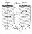
- Figure 3A essentially represents the prior art roll forming apparatus of FIG Figure 2A represents. A description of reference numerals and elements already in connection with Figure 1A or 2a are described will not be repeated here.
- the forming rollers of Figure 3A provided with a surface structure 58 which causes the workpiece material to be transported in the axial direction during roll forming.
- the surface structure 58 which causes the workpiece material to be transported in the axial direction, is designed here as a thread which, when the shaping rollers 42 rotate, generates an axial force in the direction of a later end of the valve stem. With the surface structure it is possible to use a shorter cup-shaped workpiece 16. During form rolling, a force is also exerted in the axial direction on the cup-shaped workpiece, as a result of which the material can spread not only in the radial direction but also in the axial direction during rolling.
- the surface structure 58 is designed here as a thread.
- the thread is designed with a small flank height and small pitch, which only exerts forces but does not roll a thread into the valve stem.
- the material is not only able to flow circumferentially and radially, but is also able to flow or deform axially due to the axial forces. Overall, this effect makes it possible to start with a cup-shaped workpiece with a greater wall thickness, which can significantly increase the process reliability of the method.
- Figure 3B 12 illustrates the rolling process from the cup-shaped workpiece 16 towards the valve stem end, with the material displacement being indicated by thin arrows.
- the Figures 3A and 3B can do without an axial guide if the surface structure 58 generates a sufficiently large axial force in order to reshape the rear side of the valve disk surface 24 by means of roll forming.
- Figure 3C shows a valve 4 with the form rolling device of Figures 3A and 3B was produced. It differs from the valve of Figure 2C only by the crystal structure of the material.
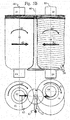
- Figure 4A shows a rolling device according to the invention which is essentially that of Figures 1A to 3A is equivalent to. A description of reference numerals and elements already associated with Figures 1A to 3A are described will not be repeated here.
- Figure 4A uses the same short cup-shaped workpiece 16 as shown in Figures 3A and 3B is shown. Instead of cylindrical rollers, whose axes are aligned parallel to each other, uses the inventive design of Figure 4A and Figure 4B hyperboloid form rollers 44, whose axes are skewed to each other.
- the rolling process is a cross-rolling process because at least the axis of one of the forming rolls is inclined with respect to the axis of the cup-shaped workpiece.
- the axes of the rollers are skewed to each other, where an angle between the axes can be specified as the angle when the axes are orthogonally projected.
- the axes 48 of the shaping rollers are each inclined at the same angle to the axis 46 of the cup-shaped workpiece 16 . Due to the inclination and rotation, an axial force is generated during rolling in the direction of what will later be the end of the valve stem. A similar effect can thus be produced as with the surface structure 58 in FIGS Figures 3A and 3B . It is of course also possible, the form rollers Figures 4A and 4B equip with a corresponding surface structure 58, as in the Figures 3A and 3B was revealed.
- the shaping rollers 44 form single-shell rotational hyperboloids whose generating lines are not straight lines but rather the profile of an inlet or outlet valve.
- Cylindrical rolls would not produce a cylindrical product but a one sheet hyperboloid since the axes of the rolls increase in distance from the closest spacing. To compensate for this effect, the reels themselves must have a one-sheet hyperboloid shape. In cross-form rolling, the rolls must also have the profile of the end product. So form profiled single-shell hyperboloid surfaces.
- the workpiece is guided here by two opposing radial guides 52, which guide the cup-shaped workpiece 16 between the hyperboloidal skew rollers 44.
- the guides must also be tracked during the roll forming process.
- the workpiece can be guided by an axial guide 54, but can also be held, guided and/or rotated by a chuck via an attachment.
- Both radial guides 52 can each be provided with at least one force transducer 66, which are each connected to a controller 68, which in turn controls the speed or the drive of at least one of the shaping rollers 44.
- the controller can be used to accurately hold the workpiece 16 between the rollers 44 and/or to reduce wear on the radial guides 52.
- Figure 4A 12 shows the hyperboloidal shaping rollers 44 in a final position after shaping.
- hyperbolic shaping rollers When using hyperbolic shaping rollers, torsional forces are generated in the shank, which turn out to be smaller with smaller roller axis angles.
- Figures 4A and 5B can also do without an axial guide, since the cross rollers generate a sufficiently large axial force. It is also possible the surface structure 58 of Figures 3A and 3B use to further increase an axial force generated during rolling.
- Figure 5A represents an inventive combination of Figures 1A , 2A , 3A and 4A dar.
- the cup-shaped workpiece is guided by a radial guide 52 from one side only.
- the left form roller 42 has the same form as in FIGS Figures 1A and 2A and the axis of the left forming roll 42 is aligned parallel to the axis of the cup-shaped workpiece 16.
- the left forming roller is as in the Figure 4A designed as a hyperbolic shaping roller 44 .
- the hyperbolic form roller 44 is also with the surface structure 58 of Figures 3A and 3B Mistake.
- the axis 50 of the hyperbolic forming roll 44 is inclined relative to the axis 48 of the left forming roll 42 and the axis 46 of the cup-shaped workpiece.
- the right-hand hyperbolic shaping roller 44 thus generates a strong axial force in the direction of the later end of the valve stem during shaping. With a suitable design, this axial force is sufficient to lengthen a short, cup-shaped workpiece 16 in the axial direction during roll forming.
- Figure 5B represents the rolling device according to the invention at the end of the rolling process.
- the hyperboloidal forming rollers 44 are located in Figure 5B in a final position after roll forming. Due to the shape of the rolls, the left hyperbolic shape roll 44 covers the upper valve stem end of the rolled valve. The shape of the rolls also requires that the valve plate covers the lower part of the left-hand hyperbolic shaping roll 44. Likewise, the lower portion of the right hyperbolic forming roll 44 partially covers the valve head of the formed workpiece 16A. The valve stem end covers the top of the contact point of the right hyperbolic forming roll 44 with the valve stem end.
- a heater opposite the radial guide 52 which heats the cup-shaped workpiece, for example via an induction heater or a gas heater, in order to keep the workpiece 16 in a temperature range in which hot rolling or hot-forming cross-rolling is possible.
- Figures 6A and 6C illustrate another additional embodiment of a workpiece and internally cooled valve Figure 6A is shown substantially corresponds to the workpiece of FIG Figure 2A .
- the work of Figure 6A provided with an outer contour 70.
- the blind hole 26 is as in Figure 2A designed as a cylindrical hole.
- the outer contour 70 together with the cylindrical blind hole 26 forms a variation in the thickness of the shaft.
- the outside of the shaft is shaped essentially cylindrically by the shaping.
- the outer contour 70 is leveled and transferred inward to the inside of the blind hole 26, an inner contour being formed inside the blind hole.
- the variation in thickness of the shaft is essentially retained, with the contour now being formed as an inner contour 72 on the inside, ie in the cavity 10 , after the forming.
- the inner contour is designed in such a way that it forms a Laval nozzle at the transition between the valve disk 6 and the valve stem 8 . It should be clear that other inner contours can also be created with this method.
Landscapes
- Engineering & Computer Science (AREA)
- Mechanical Engineering (AREA)
- Life Sciences & Earth Sciences (AREA)
- Agronomy & Crop Science (AREA)
- Chemical & Material Sciences (AREA)
- Combustion & Propulsion (AREA)
- General Engineering & Computer Science (AREA)
- Forging (AREA)
- Lift Valve (AREA)
- Details Of Valves (AREA)
Claims (19)
- Procédé de fabrication d'une soupape (4) à refroidissement interne pour moteurs à combustion interne comprenant :le fait de fournir une pièce à travailler (14, 16) comprenant une tige et un trou cylindrique (26, 28) s'étendant à partir d'une extrémité (36) de tige de soupape dans une direction axiale,le fait de former l'extrémité (36) de tige de soupape par laminage de mise en forme de la tige à un plus petit diamètre dans un laminoir transversal, un diamètre du trou cylindrique étant réduit et le trou (26, 28) étant conservé, etle fait de former par laminage de mise en forme une partie de la pièce à travailler (14, 16) adjacente à la tige de soupape (8) en une tête de soupape ;pendant le laminage de mise en forme de la tige de soupape, l'axe de la pièce à travailler (14, 16) et les axes des rouleaux de formage (42, 44) sont chacun disposés, l'un par rapport à l'autre, selon un angle de 0,5° à 6°, de préférence de 1° à 5° et de façon encore préférée de 1,5° à 4°, et, pendant le laminage de mise en forme, au moins un des rouleaux de formage (42, 44) présente une structure de surface qui effectue un transport du matériau de la pièce à travailler dans la direction axiale, au moins un des rouleaux de formage (44) ayant une surface extérieure hyperboloïde, et au moins deux rouleaux de formage (42, 44) ayant un profil de soupape d'échappement.
- Procédé de fabrication d'une soupape (4) à refroidissement interne pour moteurs à combustion interne, selon la revendication 1, dans lequel la pièce à travailler (14, 16), avant le laminage de mise en forme, comprend un diamètre d'au moins celui de la partie aplatie (6) de soupape de la soupape finie, et comprenant en outre :
le fait de former par laminage une transition entre la tête de la soupape et la tige de la soupape (8) de façon à former une gorge creuse. - Procédé de fabrication d'une soupape (4) à refroidissement interne pour moteurs à combustion interne, selon la revendication 1 ou la revendication 2, dans lequel la pièce à travailler (16) est en forme de coupelle, la pièce à travailler (14, 16) en forme de coupelle ayant un diamètre au niveau d'une partie inférieure de la pièce à travailler (16) au moins égal à celui de la partie aplatie (6) de soupape, le trou cylindrique étant un trou borgne (26) s'étendant depuis une extrémité (36) de tige de soupape vers le fond de la pièce à travailler (16) en forme de coupelle, et
le laminage de mise en forme comprend une mise en forme de la tige et une mise en forme du corps de soupape. - Procédé de fabrication d'une soupape (4) à refroidissement interne pour moteurs à combustion interne, selon la revendication 3, dans lequel une surface inférieure extérieure de la pièce à travailler (16) a déjà la forme de la partie aplatie (6) de soupape.
- Procédé de fabrication d'une soupape (4) à refroidissement interne pour moteurs à combustion interne, selon la revendication 3 ou la revendication 4, dans lequel la pièce à travailler (16) est en forme de coupelle, et dans lequel la pièce à travailler (16) en forme de coupelle présente un diamètre plus grand au niveau d'une partie inférieure de la pièce à travailler (16) que dans la zone de la tige cylindrique.
- Procédé de fabrication d'une soupape (4) à refroidissement interne pour moteurs à combustion interne, selon l'une quelconque des revendications précédentes, dans lequel
la pièce à travailler (14, 16) est maintenue entre les rouleaux au moyen de guides. - Procédé de fabrication d'une soupape (4) à refroidissement interne pour moteurs à combustion interne, selon l'une des revendications précédentes, dans lequel la pièce à travailler (14, 16) est laminée à chaud.
- Procédé de fabrication d'une soupape (4) à refroidissement interne pour moteurs à combustion interne, selon l'une quelconque des revendications précédentes, comprenant en outre :
le fait de déplacer la pièce à travailler (14, 16) dans la direction axiale vers l'extrémité de l'arbre (36) pendant le laminage. - Procédé de fabrication d'une soupape (4) à refroidissement interne pour moteurs à combustion interne, selon l'une quelconque des revendications précédentes, comprenant en outre :
le fait de faire tourner la pièce à travailler (14, 16) pendant le laminage. - Procédé de fabrication d'une soupape (4) à refroidissement interne pour moteurs à combustion interne, selon l'une quelconque des revendications précédentes, comprenant en outre :
le fait d'opérer un roulage de la tige de soupape (8) à un diamètre extérieur souhaité après qu'un diamètre intérieur souhaité de la tige de soupape (8) ait été obtenu par laminage. - Procédé de fabrication d'une soupape (4) à refroidissement interne pour moteurs à combustion interne, selon l'une quelconque des revendications précédentes, dans lequel
le fait de fournir la pièce à travailler (14, 16) comprend le fait de fournir la pièce à travailler (14, 16) avec une tige non cylindrique ayant un contour extérieur (70) et le trou cylindrique (26, 28), le fait de former l'extrémité (36) de tige de soupape par laminage de mise en forme comprend le fait de former l'extrémité (36) de tige de soupape par laminage de mise en forme de la tige à un diamètre plus petit, réduisant ainsi un diamètre du trou cylindrique et conservant un trou non cylindrique ayant un contour intérieur (72). - Dispositif de fabrication d'une soupape (4) à refroidissement interne pour moteurs à combustion interne, à partir d'une pièce à travailler (14, 16), comprenant :un laminoir pour un laminage transversal, au moins deux cylindres de formage (42, 44) ayant le profil d'une soupape d'échappement,caractérisé en ce que l'axe de la pièce à travailler (14, 16) et les axes des rouleaux de formage (42, 44) sont chacun agencés, l'un par rapport à l'autre, à un angle de 0,5° à 6°, de préférence de 1° à 5°, et de façon encore préférée de 1,5° à 4°, et en ce qu'au moins un des rouleaux (42, 44) de laminage de mise en forme a une structure de surface qui effectue un transport du matériau de la pièce à travailler dans la direction axiale, au moins un des rouleaux de formage (44) ayant une surface extérieure hyperboloïde.
- Dispositif de fabrication d'une soupape (4) à refroidissement interne selon la revendication 12, comprenant en outre :
un mandrin pouvant être inséré dans un trou (26, 28) d'une pièce à travailler (14, 16) de façon à guider la pièce à travailler (14, 16) pendant le laminage. - Dispositif de fabrication d'une soupape (4) à refroidissement interne selon la revendication 12 ou la revendication 13, comprenant en outre :
au moins un guide pour maintenir et guider la pièce à travailler (14, 16) entre les rouleaux, ledit au moins un guide comprenant un élément coulissant ou un ou plusieurs rouleaux qui reposent contre une surface extérieure de la pièce à travailler (14, 16). - Dispositif de fabrication d'une soupape (4) à refroidissement interne selon la revendication 12, 13 ou 14, comprenant en outre :au moins un capteur de force sur ledit au moins un guide, et des rouleaux de formage (42, 44) entraînés individuellement,et un contrôleur qui commande la vitesse des rouleaux de formage (42, 44) de façon à minimiser la force sur les guides.
- Dispositif de fabrication d'une soupape (4) à refroidissement interne selon l'une quelconque des revendications 12 à 15, comprenant en outre un guide axial ou un mandrin pour guider ou maintenir la pièce à travailler (14, 16) depuis le côté de la partie aplatie.
- Dispositif de fabrication d'une soupape (4) à refroidissement interne selon l'une quelconque des revendications 12 à 16, comprenant en outre un actionneur pour déplacer axialement la pièce à travailler (14, 16) depuis le bas en direction de l'extrémité (36) de la tige de soupape.
- Dispositif de fabrication d'une soupape (4) à refroidissement interne selon l'une quelconque des revendications 12 à 17, comprenant en outre un dispositif d'entraînement pour faire tourner la pièce à travailler (14, 16) sur un nombre prédéterminé de tours pendant le laminage.
- Dispositif de fabrication d'une soupape (4) à refroidissement interne selon l'une quelconque des revendications 12 à 18, comprenant en outre un élément de chauffage pour chauffer la pièce à travailler (14, 16) pendant le laminage.
Priority Applications (1)
| Application Number | Priority Date | Filing Date | Title |
|---|---|---|---|
| PL16736838T PL3368232T3 (pl) | 2015-10-26 | 2016-07-06 | Sposób oraz urządzenie do wytwarzania ochładzanego wewnętrznie zaworu dla silników spalinowych |
Applications Claiming Priority (2)
| Application Number | Priority Date | Filing Date | Title |
|---|---|---|---|
| DE102015220891.5A DE102015220891A1 (de) | 2015-10-26 | 2015-10-26 | Innengekühltes Ventil für Verbrennungsmotoren sowie Verfahren und Vorrichtung zu dessen Herstellung |
| PCT/EP2016/065965 WO2017071840A1 (fr) | 2015-10-26 | 2016-07-06 | Soupape à refroidissement intérieur pour des moteurs à combustion et procédé et dispositif de sa fabrication |
Publications (2)
| Publication Number | Publication Date |
|---|---|
| EP3368232A1 EP3368232A1 (fr) | 2018-09-05 |
| EP3368232B1 true EP3368232B1 (fr) | 2022-01-12 |
Family
ID=56404096
Family Applications (1)
| Application Number | Title | Priority Date | Filing Date |
|---|---|---|---|
| EP16736838.0A Active EP3368232B1 (fr) | 2015-10-26 | 2016-07-06 | Procédé et dispositif de fabrication d'une soupape à refroidissement intérieur pour des moteurs à combustion |
Country Status (9)
| Country | Link |
|---|---|
| US (1) | US20180304344A1 (fr) |
| EP (1) | EP3368232B1 (fr) |
| JP (1) | JP6786597B2 (fr) |
| CN (1) | CN108348982B (fr) |
| BR (1) | BR112018006586A2 (fr) |
| DE (1) | DE102015220891A1 (fr) |
| MX (1) | MX2018004262A (fr) |
| PL (1) | PL3368232T3 (fr) |
| WO (1) | WO2017071840A1 (fr) |
Families Citing this family (14)
| Publication number | Priority date | Publication date | Assignee | Title |
|---|---|---|---|---|
| DE102017113503A1 (de) * | 2017-06-20 | 2018-12-20 | Profiroll Technologies Gmbh | Umformmaschine und Druckumformverfahren |
| DE202017007601U1 (de) | 2017-06-20 | 2023-07-03 | Profiroll Technologies GmbH | Umformmaschine |
| DE102017114554A1 (de) * | 2017-06-29 | 2019-01-03 | Federal-Mogul Valvetrain Gmbh | Verfahren zur Herstellung eines innengekühlten Ventils mit einer Kühlstruktur sowie ein mit dem Verfahren hergestelltes Ventil |
| SE541253C2 (en) * | 2017-10-18 | 2019-05-14 | Gasporox Ab | System and method for determining the integrity of containers by optical measurement |
| DE102017127986A1 (de) | 2017-11-27 | 2019-05-29 | Federal-Mogul Valvetrain Gmbh | Innengekühltes Ventil mit Ventilboden und Verfahren zu dessen Herstellung |
| DE102018100413B3 (de) | 2018-01-10 | 2019-07-11 | Federal-Mogul Valvetrain Gmbh | Verfahren und Vorrichtung zum Herstellen von hohlen, innengekühlten Ventilen |
| KR102285017B1 (ko) | 2018-03-20 | 2021-08-04 | 니탄 밸브 가부시키가이샤 | 배기용 중공 포핏 밸브 |
| DE102018112291A1 (de) | 2018-05-23 | 2019-11-28 | Federal-Mogul Valvetrain Gmbh | Verfahren zur herstellung eines hohlventils für verbrennungsmotoren |
| DE102018112295A1 (de) * | 2018-05-23 | 2019-11-28 | Federal-Mogul Valvetrain Gmbh | Verfahren zur herstellung eines hohlventils mit optimierter schaftinnengeometrie für verbrennungsmotoren |
| DE102018122441A1 (de) | 2018-09-13 | 2020-03-19 | Federal-Mogul Valvetrain Gmbh | Geschweisstes hohlraumventil mit kleiner wärmeeinflusszone und verfahren zur herstellung |
| CN112752895B (zh) * | 2018-11-12 | 2023-10-13 | 日锻株式会社 | 发动机的提升阀的制造方法 |
| DE102019106209B4 (de) * | 2019-03-12 | 2025-04-24 | Federal-Mogul Valvetrain Gmbh | Verfahren zur Herstellung eines Ventilkörpers eines Hohlventils |
| JP7329201B2 (ja) | 2020-03-30 | 2023-08-18 | 株式会社Nittan | エンジンのポペットバルブの製造方法 |
| CN115245998B (zh) * | 2022-06-14 | 2024-05-17 | 攀钢集团攀枝花钢铁研究院有限公司 | 一种空心气阀合金成形方法 |
Family Cites Families (17)
| Publication number | Priority date | Publication date | Assignee | Title |
|---|---|---|---|---|
| US1950953A (en) * | 1929-03-16 | 1934-03-13 | Serimgeour William | Hollow forged valve and method of making the same |
| GB412359A (en) * | 1933-03-18 | 1934-06-28 | Jean Donat Julien | Improvements relating to the manufacture of hollow metal articles |
| GB452696A (en) * | 1935-12-28 | 1936-08-27 | William Scrimgour | Improvements in or relating to the manufacture of valves |
| DE671868C (de) * | 1936-01-01 | 1939-02-16 | Nat City Bank Of Cleveland | Verfahren zur Herstellung von hohlen Tellerventilen aus einem Sackrohr |
| US2177192A (en) * | 1936-01-27 | 1939-10-24 | Nat City Bank Of Cleveland | Method of making hollow articles |
| DE729839C (de) * | 1938-07-15 | 1943-01-04 | Auto Union A G | Verfahren zum Verschliessen des offenen Schaftendes von im Teller und Schaft hohlen Ventilen fuer Verbrennungskraftmaschinen |
| GB594439A (en) * | 1941-05-03 | 1947-11-11 | Gabriel Jeudi Dit Jeudy | Process for the manufacture of hollow valves for internal combustion engines |
| US3686911A (en) * | 1969-05-23 | 1972-08-29 | Pee Wee Masch & Apparate | Method of an apparatus for semi-hot forming of metallic workpieces in a rolling operation |
| JPS6012132B2 (ja) * | 1980-12-29 | 1985-03-30 | 三菱マテリアル株式会社 | 金属管内外面加工装置 |
| DE3929534A1 (de) * | 1989-09-06 | 1991-03-28 | Daimler Benz Ag | Verfahren zur herstellung eines ventils |
| JPH0557388A (ja) * | 1991-08-27 | 1993-03-09 | Kobe Steel Ltd | エンジンバルブの成形法 |
| JPH072257B2 (ja) * | 1993-02-22 | 1995-01-18 | 東洋アルミ株式会社 | 双曲線体の製造方法 |
| JP2003305524A (ja) * | 2002-04-09 | 2003-10-28 | Fuji Oozx Inc | エンジンバルブの製造方法 |
| US7628870B2 (en) * | 2005-02-08 | 2009-12-08 | Helio Precision Products, Inc. | Heat treated valve guide and method of making |
| JP4525461B2 (ja) * | 2005-05-13 | 2010-08-18 | 住友金属工業株式会社 | 超薄肉長尺金属缶の製造方法 |
| DK177071B1 (en) * | 2009-10-30 | 2011-05-30 | Man Diesel & Turbo Deutschland | Exhaust valve spindle for an internal combustion engine and a method of manufacture thereof |
| JP2014084725A (ja) * | 2012-10-19 | 2014-05-12 | Mitsubishi Heavy Ind Ltd | エンジンバルブ及びその製造方法 |
-
2015
- 2015-10-26 DE DE102015220891.5A patent/DE102015220891A1/de not_active Ceased
-
2016
- 2016-07-06 BR BR112018006586-2A patent/BR112018006586A2/pt not_active Application Discontinuation
- 2016-07-06 PL PL16736838T patent/PL3368232T3/pl unknown
- 2016-07-06 MX MX2018004262A patent/MX2018004262A/es unknown
- 2016-07-06 CN CN201680060659.3A patent/CN108348982B/zh active Active
- 2016-07-06 WO PCT/EP2016/065965 patent/WO2017071840A1/fr not_active Ceased
- 2016-07-06 EP EP16736838.0A patent/EP3368232B1/fr active Active
- 2016-07-06 JP JP2018521406A patent/JP6786597B2/ja active Active
- 2016-07-06 US US15/770,991 patent/US20180304344A1/en not_active Abandoned
Also Published As
| Publication number | Publication date |
|---|---|
| CN108348982B (zh) | 2019-10-15 |
| JP6786597B2 (ja) | 2020-11-18 |
| CN108348982A (zh) | 2018-07-31 |
| WO2017071840A1 (fr) | 2017-05-04 |
| BR112018006586A2 (pt) | 2018-10-23 |
| JP2019506555A (ja) | 2019-03-07 |
| US20180304344A1 (en) | 2018-10-25 |
| DE102015220891A1 (de) | 2017-04-27 |
| EP3368232A1 (fr) | 2018-09-05 |
| PL3368232T3 (pl) | 2022-05-02 |
| MX2018004262A (es) | 2018-08-01 |
Similar Documents
| Publication | Publication Date | Title |
|---|---|---|
| EP3368232B1 (fr) | Procédé et dispositif de fabrication d'une soupape à refroidissement intérieur pour des moteurs à combustion | |
| EP3049200B1 (fr) | Procédé de forgeage à chaud d'un corps creux sans soudure en matériau difficile à déformer | |
| DE102012017525B4 (de) | Verfahren zur umformenden Herstellung eines Zahnrads mit Außenverzahnung, sowie nach diesem Verfahren herstellbares Zahnrad mit Außenverzahnung | |
| DE10159776C2 (de) | Herstellung eines Gelenkinnenteils | |
| EP3582910B1 (fr) | Procédé de laminage de type à clavette transversale de soupapes à disque | |
| DE2415549C3 (de) | Vorrichtung für die spanlose Kaltverformung eines Rohlings | |
| EP3481700B1 (fr) | Crémaillère et procédé de fabrication d'une crémaillère pour un mécanisme de direction d'un véhicule automobile | |
| DE102012005106B4 (de) | Verfahren zur Herstellung einer Hohlwelle und Vorrichtung hierfür | |
| DE102019106209B4 (de) | Verfahren zur Herstellung eines Ventilkörpers eines Hohlventils | |
| EP3481698B1 (fr) | Crémaillère et procédé de fabrication d'une crémaillère pour un mécanisme de direction d'un véhicule automobile | |
| DE602005001600T2 (de) | Verfahren zum Stauchen eines metallischen Rohlings durch Warmverarbeitung, Verfahren zur Vorbereitung eines Rohlings für ein Schmiedeverfahren gemäss dem Stauchverfahren und Vorrichtung zur Durchführung des Stauchverfahrens. | |
| DE10005578A1 (de) | Verfahren und Drückwalzvorrichtung zum Herstellen eines Hohlkörpers | |
| EP3898025B1 (fr) | Procédé pour produire une préforme pour une soupape à tige creuse pour des moteurs à combustion interne | |
| DE102015118495A1 (de) | Verfahren zur Herstellung eines Ventilstößels sowie Ventilstößel | |
| DE69616768T2 (de) | Verfahren zur Herstellung eines Spannbackens für einen Spannfutter | |
| EP3481699B1 (fr) | Crémaillère et procédé de fabrication d'une crémaillère pour un véhicule automobile | |
| DE2903847C2 (fr) | ||
| DE102012015308B4 (de) | Umformvorrichtung und Umformverfahren zur Oberflächenbearbeitung eines Motorbauteils | |
| DE69812861T2 (de) | Walzwerk zur herstellung von axialsymmetrischen teilen | |
| EP3122490A1 (fr) | Procédé et dispositif de façonnage de tronçons profilés extrudés à partir de magnésium ou d'alliages de magnésium et élément de construction léger fabriqué à partir de ceux-ci | |
| DE102012102951A1 (de) | Verfahren und Vorrichtung zum Fügen eines Nietelements | |
| EP2734318B1 (fr) | Cylindre pour laminoir à couronnes | |
| EP3877102B1 (fr) | Procédé de fabrication d'une soupape creuse pour moteurs à combustion interne | |
| EP4103341B1 (fr) | Procédé de fabrication d'un élément d'arbre de transmission, procédé de fabrication d'un arbre de transmission et élément d'arbre de transmission fabriqué selon un tel procédé | |
| DE19602137A1 (de) | Verfahren und Vorrichtungen zur Herstellung von Rohren mit profilierter Wand (gaufrierten Rohren) |
Legal Events
| Date | Code | Title | Description |
|---|---|---|---|
| STAA | Information on the status of an ep patent application or granted ep patent |
Free format text: STATUS: THE INTERNATIONAL PUBLICATION HAS BEEN MADE |
|
| PUAI | Public reference made under article 153(3) epc to a published international application that has entered the european phase |
Free format text: ORIGINAL CODE: 0009012 |
|
| STAA | Information on the status of an ep patent application or granted ep patent |
Free format text: STATUS: REQUEST FOR EXAMINATION WAS MADE |
|
| 17P | Request for examination filed |
Effective date: 20180207 |
|
| AK | Designated contracting states |
Kind code of ref document: A1 Designated state(s): AL AT BE BG CH CY CZ DE DK EE ES FI FR GB GR HR HU IE IS IT LI LT LU LV MC MK MT NL NO PL PT RO RS SE SI SK SM TR |
|
| AX | Request for extension of the european patent |
Extension state: BA ME |
|
| DAV | Request for validation of the european patent (deleted) | ||
| DAX | Request for extension of the european patent (deleted) | ||
| GRAP | Despatch of communication of intention to grant a patent |
Free format text: ORIGINAL CODE: EPIDOSNIGR1 |
|
| STAA | Information on the status of an ep patent application or granted ep patent |
Free format text: STATUS: GRANT OF PATENT IS INTENDED |
|
| INTG | Intention to grant announced |
Effective date: 20211005 |
|
| GRAS | Grant fee paid |
Free format text: ORIGINAL CODE: EPIDOSNIGR3 |
|
| GRAA | (expected) grant |
Free format text: ORIGINAL CODE: 0009210 |
|
| STAA | Information on the status of an ep patent application or granted ep patent |
Free format text: STATUS: THE PATENT HAS BEEN GRANTED |
|
| AK | Designated contracting states |
Kind code of ref document: B1 Designated state(s): AL AT BE BG CH CY CZ DE DK EE ES FI FR GB GR HR HU IE IS IT LI LT LU LV MC MK MT NL NO PL PT RO RS SE SI SK SM TR |
|
| REG | Reference to a national code |
Ref country code: GB Ref legal event code: FG4D Free format text: NOT ENGLISH |
|
| REG | Reference to a national code |
Ref country code: CH Ref legal event code: EP |
|
| REG | Reference to a national code |
Ref country code: DE Ref legal event code: R096 Ref document number: 502016014395 Country of ref document: DE |
|
| REG | Reference to a national code |
Ref country code: IE Ref legal event code: FG4D Free format text: LANGUAGE OF EP DOCUMENT: GERMAN |
|
| REG | Reference to a national code |
Ref country code: AT Ref legal event code: REF Ref document number: 1462030 Country of ref document: AT Kind code of ref document: T Effective date: 20220215 |
|
| REG | Reference to a national code |
Ref country code: LT Ref legal event code: MG9D |
|
| REG | Reference to a national code |
Ref country code: NL Ref legal event code: MP Effective date: 20220112 |
|
| PG25 | Lapsed in a contracting state [announced via postgrant information from national office to epo] |
Ref country code: NL Free format text: LAPSE BECAUSE OF FAILURE TO SUBMIT A TRANSLATION OF THE DESCRIPTION OR TO PAY THE FEE WITHIN THE PRESCRIBED TIME-LIMIT Effective date: 20220112 |
|
| PG25 | Lapsed in a contracting state [announced via postgrant information from national office to epo] |
Ref country code: SE Free format text: LAPSE BECAUSE OF FAILURE TO SUBMIT A TRANSLATION OF THE DESCRIPTION OR TO PAY THE FEE WITHIN THE PRESCRIBED TIME-LIMIT Effective date: 20220112 Ref country code: RS Free format text: LAPSE BECAUSE OF FAILURE TO SUBMIT A TRANSLATION OF THE DESCRIPTION OR TO PAY THE FEE WITHIN THE PRESCRIBED TIME-LIMIT Effective date: 20220112 Ref country code: PT Free format text: LAPSE BECAUSE OF FAILURE TO SUBMIT A TRANSLATION OF THE DESCRIPTION OR TO PAY THE FEE WITHIN THE PRESCRIBED TIME-LIMIT Effective date: 20220512 Ref country code: NO Free format text: LAPSE BECAUSE OF FAILURE TO SUBMIT A TRANSLATION OF THE DESCRIPTION OR TO PAY THE FEE WITHIN THE PRESCRIBED TIME-LIMIT Effective date: 20220412 Ref country code: LT Free format text: LAPSE BECAUSE OF FAILURE TO SUBMIT A TRANSLATION OF THE DESCRIPTION OR TO PAY THE FEE WITHIN THE PRESCRIBED TIME-LIMIT Effective date: 20220112 Ref country code: HR Free format text: LAPSE BECAUSE OF FAILURE TO SUBMIT A TRANSLATION OF THE DESCRIPTION OR TO PAY THE FEE WITHIN THE PRESCRIBED TIME-LIMIT Effective date: 20220112 Ref country code: ES Free format text: LAPSE BECAUSE OF FAILURE TO SUBMIT A TRANSLATION OF THE DESCRIPTION OR TO PAY THE FEE WITHIN THE PRESCRIBED TIME-LIMIT Effective date: 20220112 Ref country code: BG Free format text: LAPSE BECAUSE OF FAILURE TO SUBMIT A TRANSLATION OF THE DESCRIPTION OR TO PAY THE FEE WITHIN THE PRESCRIBED TIME-LIMIT Effective date: 20220412 |
|
| PG25 | Lapsed in a contracting state [announced via postgrant information from national office to epo] |
Ref country code: LV Free format text: LAPSE BECAUSE OF FAILURE TO SUBMIT A TRANSLATION OF THE DESCRIPTION OR TO PAY THE FEE WITHIN THE PRESCRIBED TIME-LIMIT Effective date: 20220112 Ref country code: GR Free format text: LAPSE BECAUSE OF FAILURE TO SUBMIT A TRANSLATION OF THE DESCRIPTION OR TO PAY THE FEE WITHIN THE PRESCRIBED TIME-LIMIT Effective date: 20220413 Ref country code: FI Free format text: LAPSE BECAUSE OF FAILURE TO SUBMIT A TRANSLATION OF THE DESCRIPTION OR TO PAY THE FEE WITHIN THE PRESCRIBED TIME-LIMIT Effective date: 20220112 |
|
| PG25 | Lapsed in a contracting state [announced via postgrant information from national office to epo] |
Ref country code: IS Free format text: LAPSE BECAUSE OF FAILURE TO SUBMIT A TRANSLATION OF THE DESCRIPTION OR TO PAY THE FEE WITHIN THE PRESCRIBED TIME-LIMIT Effective date: 20220512 |
|
| REG | Reference to a national code |
Ref country code: DE Ref legal event code: R097 Ref document number: 502016014395 Country of ref document: DE |
|
| PG25 | Lapsed in a contracting state [announced via postgrant information from national office to epo] |
Ref country code: SM Free format text: LAPSE BECAUSE OF FAILURE TO SUBMIT A TRANSLATION OF THE DESCRIPTION OR TO PAY THE FEE WITHIN THE PRESCRIBED TIME-LIMIT Effective date: 20220112 Ref country code: SK Free format text: LAPSE BECAUSE OF FAILURE TO SUBMIT A TRANSLATION OF THE DESCRIPTION OR TO PAY THE FEE WITHIN THE PRESCRIBED TIME-LIMIT Effective date: 20220112 Ref country code: RO Free format text: LAPSE BECAUSE OF FAILURE TO SUBMIT A TRANSLATION OF THE DESCRIPTION OR TO PAY THE FEE WITHIN THE PRESCRIBED TIME-LIMIT Effective date: 20220112 Ref country code: EE Free format text: LAPSE BECAUSE OF FAILURE TO SUBMIT A TRANSLATION OF THE DESCRIPTION OR TO PAY THE FEE WITHIN THE PRESCRIBED TIME-LIMIT Effective date: 20220112 Ref country code: DK Free format text: LAPSE BECAUSE OF FAILURE TO SUBMIT A TRANSLATION OF THE DESCRIPTION OR TO PAY THE FEE WITHIN THE PRESCRIBED TIME-LIMIT Effective date: 20220112 |
|
| PLBE | No opposition filed within time limit |
Free format text: ORIGINAL CODE: 0009261 |
|
| STAA | Information on the status of an ep patent application or granted ep patent |
Free format text: STATUS: NO OPPOSITION FILED WITHIN TIME LIMIT |
|
| PG25 | Lapsed in a contracting state [announced via postgrant information from national office to epo] |
Ref country code: AL Free format text: LAPSE BECAUSE OF FAILURE TO SUBMIT A TRANSLATION OF THE DESCRIPTION OR TO PAY THE FEE WITHIN THE PRESCRIBED TIME-LIMIT Effective date: 20220112 |
|
| 26N | No opposition filed |
Effective date: 20221013 |
|
| PG25 | Lapsed in a contracting state [announced via postgrant information from national office to epo] |
Ref country code: SI Free format text: LAPSE BECAUSE OF FAILURE TO SUBMIT A TRANSLATION OF THE DESCRIPTION OR TO PAY THE FEE WITHIN THE PRESCRIBED TIME-LIMIT Effective date: 20220112 Ref country code: MC Free format text: LAPSE BECAUSE OF FAILURE TO SUBMIT A TRANSLATION OF THE DESCRIPTION OR TO PAY THE FEE WITHIN THE PRESCRIBED TIME-LIMIT Effective date: 20220112 |
|
| REG | Reference to a national code |
Ref country code: CH Ref legal event code: PL |
|
| GBPC | Gb: european patent ceased through non-payment of renewal fee |
Effective date: 20220706 |
|
| REG | Reference to a national code |
Ref country code: BE Ref legal event code: MM Effective date: 20220731 |
|
| PG25 | Lapsed in a contracting state [announced via postgrant information from national office to epo] |
Ref country code: LU Free format text: LAPSE BECAUSE OF NON-PAYMENT OF DUE FEES Effective date: 20220706 Ref country code: LI Free format text: LAPSE BECAUSE OF NON-PAYMENT OF DUE FEES Effective date: 20220731 Ref country code: CH Free format text: LAPSE BECAUSE OF NON-PAYMENT OF DUE FEES Effective date: 20220731 |
|
| PG25 | Lapsed in a contracting state [announced via postgrant information from national office to epo] |
Ref country code: GB Free format text: LAPSE BECAUSE OF NON-PAYMENT OF DUE FEES Effective date: 20220706 Ref country code: BE Free format text: LAPSE BECAUSE OF NON-PAYMENT OF DUE FEES Effective date: 20220731 |
|
| P01 | Opt-out of the competence of the unified patent court (upc) registered |
Effective date: 20230528 |
|
| PG25 | Lapsed in a contracting state [announced via postgrant information from national office to epo] |
Ref country code: IE Free format text: LAPSE BECAUSE OF NON-PAYMENT OF DUE FEES Effective date: 20220706 |
|
| REG | Reference to a national code |
Ref country code: AT Ref legal event code: MM01 Ref document number: 1462030 Country of ref document: AT Kind code of ref document: T Effective date: 20220706 |
|
| PG25 | Lapsed in a contracting state [announced via postgrant information from national office to epo] |
Ref country code: AT Free format text: LAPSE BECAUSE OF NON-PAYMENT OF DUE FEES Effective date: 20220706 |
|
| PG25 | Lapsed in a contracting state [announced via postgrant information from national office to epo] |
Ref country code: HU Free format text: LAPSE BECAUSE OF FAILURE TO SUBMIT A TRANSLATION OF THE DESCRIPTION OR TO PAY THE FEE WITHIN THE PRESCRIBED TIME-LIMIT; INVALID AB INITIO Effective date: 20160706 |
|
| PG25 | Lapsed in a contracting state [announced via postgrant information from national office to epo] |
Ref country code: MK Free format text: LAPSE BECAUSE OF FAILURE TO SUBMIT A TRANSLATION OF THE DESCRIPTION OR TO PAY THE FEE WITHIN THE PRESCRIBED TIME-LIMIT Effective date: 20220112 Ref country code: CY Free format text: LAPSE BECAUSE OF FAILURE TO SUBMIT A TRANSLATION OF THE DESCRIPTION OR TO PAY THE FEE WITHIN THE PRESCRIBED TIME-LIMIT Effective date: 20220112 |
|
| PG25 | Lapsed in a contracting state [announced via postgrant information from national office to epo] |
Ref country code: MT Free format text: LAPSE BECAUSE OF FAILURE TO SUBMIT A TRANSLATION OF THE DESCRIPTION OR TO PAY THE FEE WITHIN THE PRESCRIBED TIME-LIMIT Effective date: 20220112 |
|
| PGFP | Annual fee paid to national office [announced via postgrant information from national office to epo] |
Ref country code: PL Payment date: 20250620 Year of fee payment: 10 |
|
| PGFP | Annual fee paid to national office [announced via postgrant information from national office to epo] |
Ref country code: FR Payment date: 20250620 Year of fee payment: 10 |
|
| PGFP | Annual fee paid to national office [announced via postgrant information from national office to epo] |
Ref country code: TR Payment date: 20250626 Year of fee payment: 10 |
|
| PGFP | Annual fee paid to national office [announced via postgrant information from national office to epo] |
Ref country code: CZ Payment date: 20250627 Year of fee payment: 10 |
|
| PGFP | Annual fee paid to national office [announced via postgrant information from national office to epo] |
Ref country code: DE Payment date: 20250620 Year of fee payment: 10 |
|
| PGFP | Annual fee paid to national office [announced via postgrant information from national office to epo] |
Ref country code: IT Payment date: 20250619 Year of fee payment: 10 |